

Page 1
A. J. ANTUNES & CO. www.ajantunes.com 180 Kehoe Blvd., Carol Stream, Illinois 60188
Model D Installation Information
IMPORTANT
Please read these instructions carefully to assure
correct installation. This equipment must be
installed only by a licensed electrician who is
experienced with combustion safeguard control
systems and understands the functions of interlocking switches, such as gas pressure switches.
Prior to being put into operation in conjunction
with the combustion safeguard systems, all
switches should be tested for proper range setting
and proper wiring. Check piping connections and
switch house for leaks with a soap bubble test. All
exhaust fans and blowers should be inspected and
checked for proper rotation prior to starting up.
Model D Switches
You are installing one of the finest switches of its type on
the market. The Model D is adjustable within its range as
shown on the range scale located on the front of the unit.
The latch position in the reset models and the level indicator position in the recycle models shows whether the
switch is on or off.
Specifications
Electrical Ratings: 4A, 1/8 HP @ 125 VAC; 3A, 1/4 HP
@ 25 VAC.; Pilot Duty 125 VA @125-250 VAC
Max. Surge Pressure: 10 PSI
Max Operating Pressure: 8 PSIG
Max. Ambient Operating Temperature: 140°F (60°C)
Min. Ambient Operating Temperature: -40°F (-40°C)
Shipping Weight: HGP-D, LGP-D, RHGP-D, RLGP-D:
2 lbs. (.9 kg)
HLGP-D, RHLGP-D: 4 lbs. (1.8 kg)
Options:
Panel Mount
Dust Proof
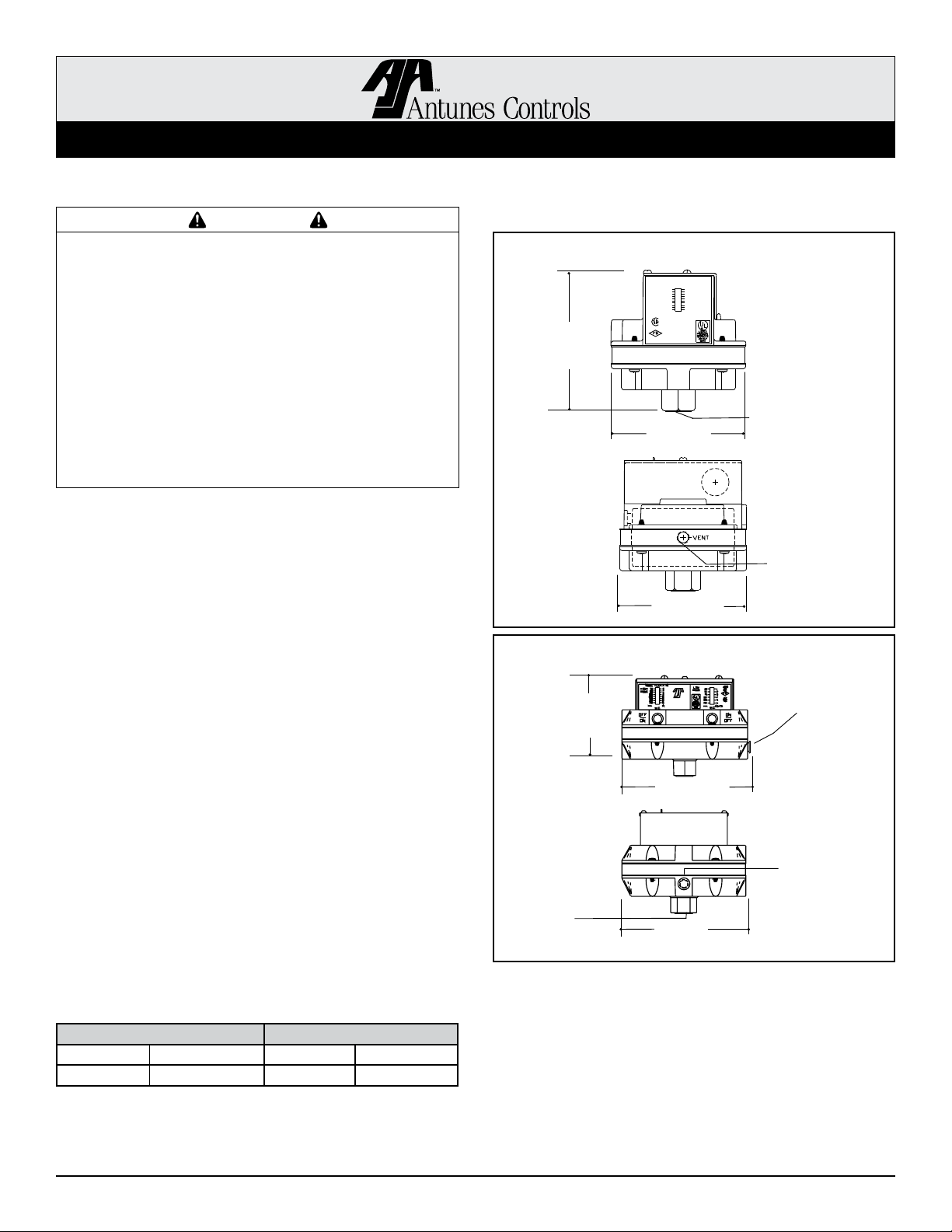
Dimensions
FRONT
4 1/16”
(103 mm)
SIDE
High Low Gas Pressure Switch
FRONT
4 1/4”
(108 mm)
SIDE
3/8” NPT
High Pressure
Inlet
Single Gas Pressure Switch
4 1/16”
(103 mm) dia.
4 1/16”
(103 mm) dia.
5 5/8”
(143 mm)
5 3/8”
(136 mm)
Gas Inlet 1/4” NPT
Vent 1/8” NPT
NOTE: Dimensions
are for reference only.
NOTE: Dimensions
are for reference only.
1/8” NPT
Gas Vent
1/8” NPT
Low Pressure
Gas Vent
Range Available
High Gas Pressure Low Gas Pressure
5-28” W.C. 125-700 mm 2-14” W.C. 50-350 mm
10-50” W.C. 250-1250 mm 10-50” W.C. 250-1250 mm
1-630-784-1000 Fax: 630-784-1651 Page 1 of 4 P/N 1011088 06/10
1-800-253-2991
Page 2
A. J. ANTUNES & CO. www.ajantunes.com 180 Kehoe Blvd., Carol Stream, Illinois 60188
Model D Installation Information
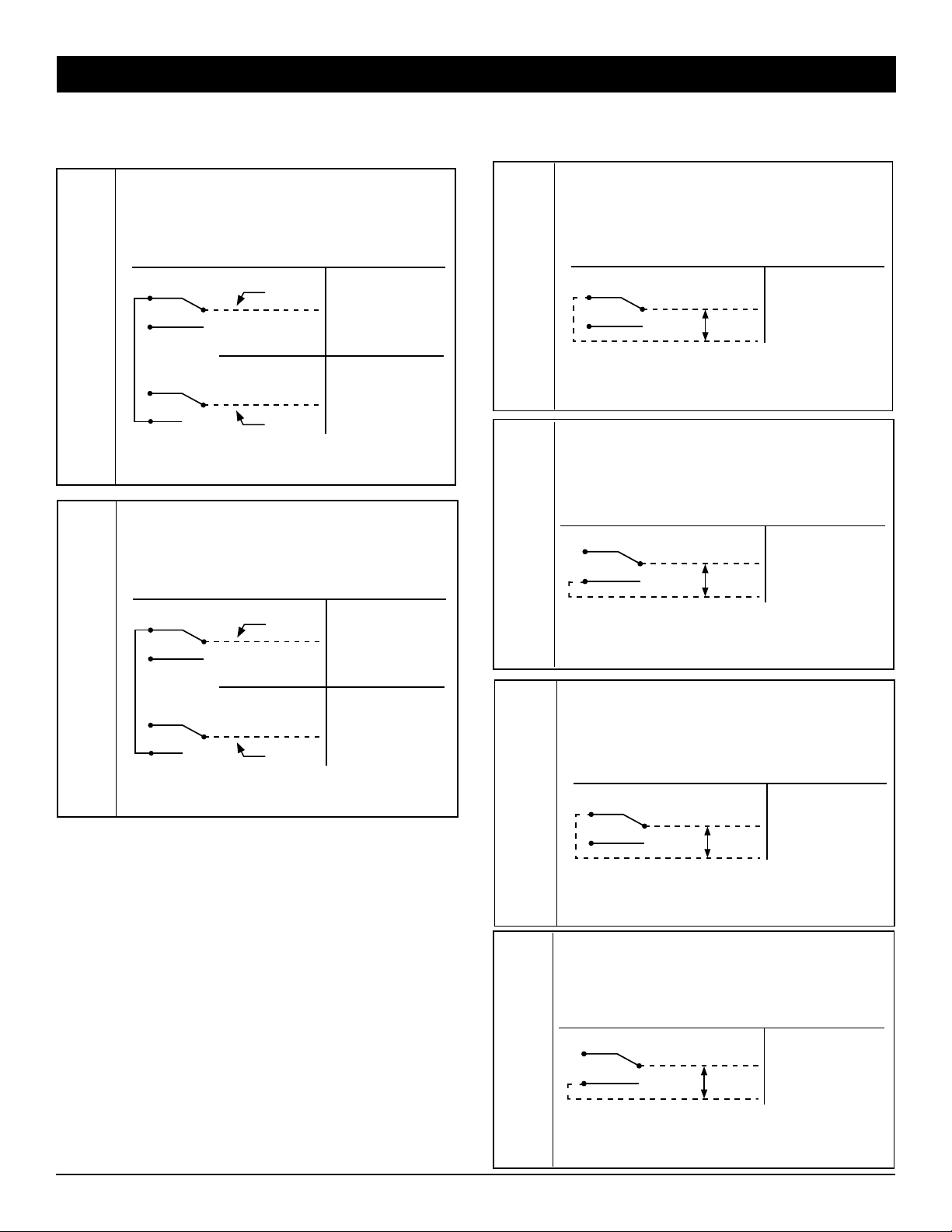
Electrical Wiring - Combination Models
Model: HLGP-D
Duty: High Low Gas Reset Switch
Elec. Rating: 4A, 125 VAC, 3A, 250-277 VAC
1/8 HP @125 VAC, 1/4 HP @ 250 VAC
Pilot Duty: 125 VA, 125-250 VAC
Reset lever will latch
when gas pressure is
below setting
Reset lever will latch
when gas pressure is
above setting
Contacts C & NC
break when pressure
rises above setting
Contacts C & NO
make when pressure
rises above setting
Reset
HLGP-D
Reset
RHLGP-D
High Gas
NC
NO
C
By Others
Indicator On
Indicator Off
NC
NO
Low Gas
Field wiring to be rated @75ºC for max 120ºF Ambient
Field wiring to be rated @90ºC for max 140ºF Ambient
Max Surge Pressure: 10 PSIG
C
By Others
Model: RHLGP-D
Duty: High Low Gas Reset Switch
Elec. Rating: 4A, 125 VAC, 3A, 250-277 VAC
1/8 HP @125 VAC, 1/4 HP @ 250 VAC
Pilot Duty: 125 VA, 125-250 VAC
High Gas
NC
NO
C
By Others
Indicator On
Indicator Off
NC
NO
Low Gas
Field wiring to be rated @75ºC for max 120ºF Ambient
Field wiring to be rated @90ºC for max 140ºF Ambient
Max Surge Pressure: 10 PSIG
C
By Others
Electrical Wiring - Single Models
Model: HGP-D
Duty: High Gas Reset Switch
Elec. Rating: 4A, 125 VAC, 3A, 250-277 VAC
1/8 HP @125 VAC, 1/4 HP @ 250 VAC
Pilot Duty: 125 VA, 125-250 VAC
Reset
HGP-D
Reset
LGP-D
Recycle
RHGP-D
NC
NO
C
By Others
Indicator On
Field wiring to be rated @75ºC for max 120ºF Ambient
Field wiring to be rated @90ºC for max 140ºF Ambient
Max Surge Pressure: 10 PSIG
Model: LGP-D
Duty: Low Gas Reset Switch
Elec. Rating: 4A, 125 VAC, 3A, 250-277 VAC
1/8 HP @125 VAC, 1/4 HP @ 250 VAC
Pilot Duty: 125 VA, 125-250 VAC
NC
NO
C
By Others
Indicator Off
Field wiring to be rated @75ºC for max 120ºF Ambient
Field wiring to be rated @90ºC for max 140ºF Ambient
Max Surge Pressure: 10 PSIG
Model: RHGP-D
Duty: High Gas Recycle Switch
Elec. Rating: 4A, 125 VAC, 3A, 250-277 VAC
1/8 HP @125 VAC, 1/4 HP @ 250 VAC
Pilot Duty: 125 VA, 125-250 VAC
NC
NO
C
By Others
Indicator On
Field wiring to be rated @75ºC for max 120ºF Ambient
Field wiring to be rated @90ºC for max 140ºF Ambient
Max Surge Pressure: 10 PSIG
Reset lever will latch
when gas pressure is
below setting contact
C & NC make
Reset lever will latch
when gas pressure is
above setting contact
C & NO make
Contacts C & NC
break when pressure
rises above setting
Model: RLGP-D
Duty: Low Gas Recycle Switch
Elec. Rating: 4A, 125 VAC, 3A, 250-277 VAC
1/8 HP @125 VAC, 1/4 HP @ 250 VAC
Pilot Duty: 125 VA, 125-250 VAC
Recycle
RLGP-D
NC
NO
C
By Others
Contacts C & NO
make when pressure
rises above setting
Indicator Off
Field wiring to be rated @75ºC for max 120ºF Ambient
Field wiring to be rated @90ºC for max 140ºF Ambient
Max Surge Pressure: 10 PSIG
1-630-784-1000 Fax: 630-784-1651 Page 2 of 4 P/N 1011088 06/10
1-800-253-2991
Page 3
A. J. ANTUNES & CO. www.ajantunes.com 180 Kehoe Blvd., Carol Stream, Illinois 60188
Model D Installation Information
Operation
Low Gas Pressure: Low gas pressure switches break
the electrical circuit on pressure drop at the point when
gas pressure becomes lower than the indicated set
pressure.
Before the manual reset latch can be properly latched,
gas pressure in the chamber must be higher than the
indicated setting. The position of the reset latch on the top
cover of the switch shows whether reset latch is in the on
or off position. Reset latch must be in “on” position after
latching to be properly set.
High Gas Pressure: High gas pressure switches break
the electrical circuit when pressure rises above the
indicated preset pressure. The reset latch should be
latched in the “on” position if the gas pressure in the
switch chamber is below the indicated high setting.
Recycle Models: High and Low Gas Pressure Recycle
models operate automatically and do not need to be
reset. Otherwise they are constructed, adjusted, and
operate in the same manner as the reset models.
Combination Models: The combination unit contains
one high pressure unit and one low pressure unit, in the
ranges you select. They may be either reset or recycle
type. Each unit has an on/off indicator and its own range
scale indicator.
Mounting
All gas pressure switches must be mounted in a horizontal
position with the inlet stem down. Switches should be
reasonably level but do not require accurate leveling.
Single gas switch models have a 1/4” NPT. gas inlet.
Double combination Hi-Lo switches have a 3/8” NPT. for high
pressure inlet and a 1/8” NPT. for low pressure inlet.
Gas vent outlets are 1/8” NPT. on all models.
Piping can be either standard black pipe or aluminum tubing.
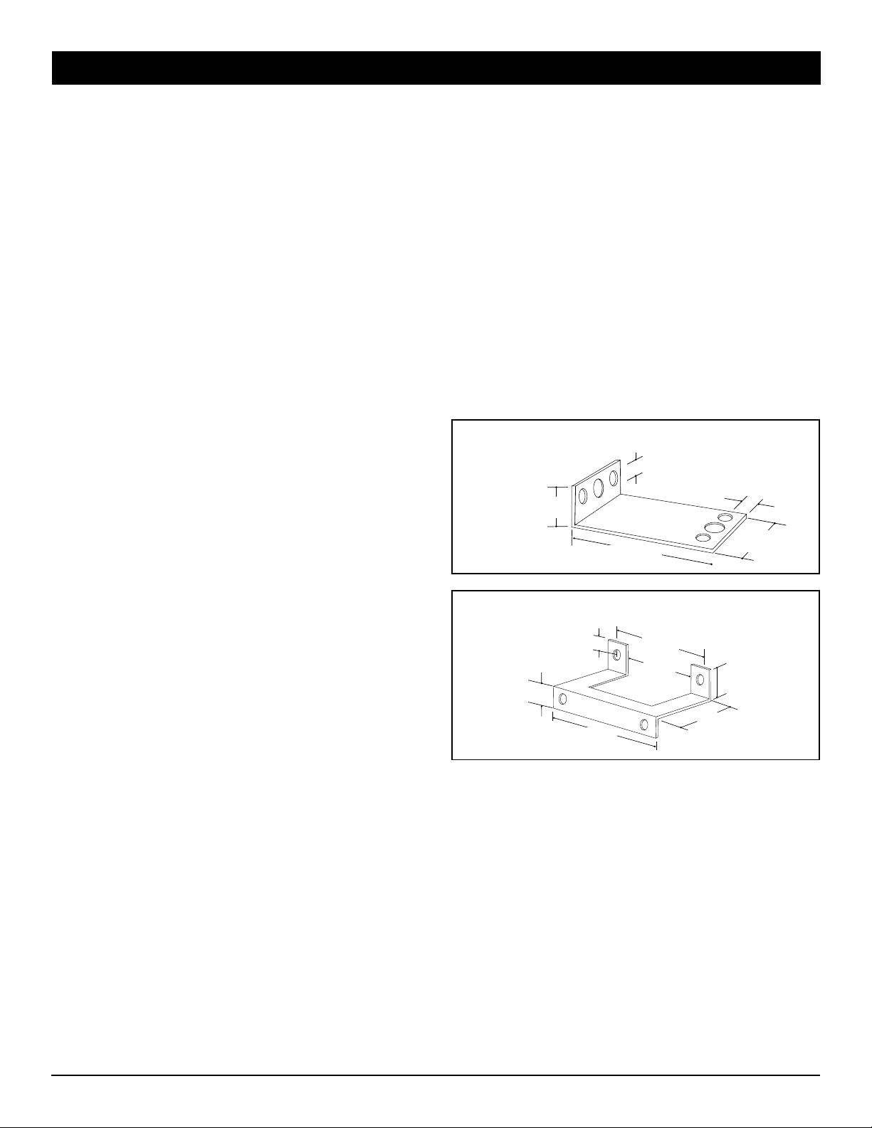
All switches can be supported by the inlet pipe, but optional
mounting brackets are available if needed.
All switches have been factory-calibrated and tested for leaks.
However, it is recommended that after the installation is
completed, switch, gas pipe inlets, and connections be tested for
leaks with a soap bubble test.
Single Models
2 5/8”
(67 mm)
1/2”
(13 mm)
7/8”
(22 mm)
1 1/8”
(28 mm)
Large
Mounting
Holes:
5/16”
(8 mm) dia.
Small
Mounting
Holes:
7/32”
(6 mm) dia.
7/8”
(22 mm)
All Mounting
Holes:
5/16”
(8 mm) dia.
1”
(25 mm)
Double Models
1/2”
(13 mm)
7/8”
(22 mm)
3 3/4”
(95 mm)
2”
(51 mm)
1/2”
(13 mm)
1”
(25 mm)
1-630-784-1000 Fax: 630-784-1651 Page 3 of 4 P/N 1011088 06/10
1-800-253-2991
Page 4
A. J. ANTUNES & CO. www.ajantunes.com 180 Kehoe Blvd., Carol Stream, Illinois 60188
Model D Installation Information
Warranty
1. Antunes Controls products are guaranteed to be free
from mechanical and electrical defects for a period of
one year from date of shipment under normal use and
service provided installation is made in accordance
with manufacturers’ recommendations.
2. Parts deemed defective shall be repaired or replaced
at manufacturers option and at manufacturers expense
but shall not include foreign or federal excise taxes,
state or municipal sale or use taxes, all such taxes
not limited to the foregoing being responsibility of the
purchaser.
3. No charge for travel and/or mileage will be allowed to
purchaser.
4. Antunes Controls reserves the right to make changes
in design or make any improvements on any products.
The right is always reserved to modify our equipment
because of new technology, underwriter’s requirements
and/or government regulations.
5. The following are not covered under warranty:
a. Failure from neglect, abuse, careless handling and
mis-application of unit.
Limitation of Liability: If it is understood and agreed
that seller’s liability whether in contract, in tort, under
any warranty, in negligence or otherwise, shall not
exceed the return of the amount of the purchase price
paid by purchaser and under no circumstances shall
seller be liable for special, indirect or consequential
damages. The price stated for the equipment is a
consideration in limiting seller’s liability. No action,
regardless of form, arising out of the transactions may
be brought by purchaser more than one year after the
cause of action has accrued.
b. Failure to observe guidelines for installation or
improper voltage hook-up.
c. Failure caused by improper maintenance.
d. Unless specifically allowed by Antunes Controls, no
other charges may be included under warranty.
A.J. Antunes & Co.
Headquarters/Manufacturing
180 Kehoe Boulevard
Carol Stream, Illinois 60188 USA
Phone (630) 784-1000
Toll Free (800) 253-2991
Fax: (630) 784-1650
www.ajantunes.com
Antunes Equipment
Manufacturing (Suzhou) Ltd.,
9 Hou Ju Road, Building #24,
S&T Park, SND
Suzhou, Jiangsu, China 215011
Phone: 86-512-6841-3637
Fax: 86-512-6841-3907
1-630-784-1000 Fax: 630-784-1651 Page 4 of 4 P/N 1011088 06/10
1-800-253-2991
 Loading...