


MDT
Multiband Dynamics Toolª
for TDM
™
UserÕs Manual
v 4.4
MDT UserÕs Manual
i

MDT – Multiband Dynamics Tool™
© 1999 Antares Audio Technologies
All Rights Reserved
Antares Audio Technologies
464 Monterey Ave, 2nd Floor
Los Gatos, CA, 95030
(408) 399-0008, (888) 332-2636
web: www.antaresTech.com
MDT Ð Multiband Dynamics Tool software and this user manual are protected by copyright law. Making copies, adaptations, or derivative works
without prior written authorization of Antares Audio Technologies, is prohibited by law and constitutes a punishable violation of the law.
Antares Audio Technologies retains all ownership rights to the MDT software and other software offered by Antares Audio Technologies and their
documentation. Use of MDT is limited by the license agreement printed on
the envelope containing your original diskette.
All trademarks are the property of their respective holders.
MDT License Agreement
ii
MDT UserÕs Manual
Carefully read all the terms and conditions of this license agreement. If you do not agree with
the terms and conditions of this Agreement, notifying Antares Audio Technologies and destroying all copies of the manual, and erasing MDT from all machine-readable media, whether on-line or on archival copies.
Software License Agreement
Antares Audio Technologies grants you a non-transferable, non-exclusive license to use
MDT, under the terms and conditions stated in this agreement. Use of MDT indicates your
agreement to the following terms and conditions.
License
You may:
1. use MDT on only one computer at a time;
2. physically transfer the program from one computer to another, provided that the
program is used on only one computer at a time.
You may not:
1. make copies of MDT or of the user manual in whole or in part except as expressly
provided for in this agreement. Your right to copy MDT and the user manual is lim-

ited by copyright law. Making copies, verbal or media translations, adaptations, derivative works, or telecommunication data transmission of MDT without prior
written authorization of Antares Audio Technologies, is prohibited by law and constitutes a punishable violation of the law.
2. make alteration or modifications to MDT (or any copy) or disassemble or de-compile MDT (or any copy), or attempt to discover the source code of MDT.
3. sub license, lease, lend, rent, or grant other rights in all or any portion of MDT (or
any copy) to others.
Term of the Agreement
This agreement is effective until terminated by you or Antares Audio Technologies. You may
terminate the agreement at any time by notifying Antares Audio Technologies and destroying
all copies of the manual, and erasing MDT from all machine-readable media, whether on-line
or on archival copies.
In the event of breach of any of the terms of this agreement, you shall pay the attorney's fees
of Antares Audio Technologies that are reasonably necessary to enforce the agreement plus
resulting damages.
Limited Warranty and Disclaimer
MDT AND ACCOMPANYING MATERIALS ARE PROVIDED “AS IS” WITHOUT
WARRANTY OF ANY KIND, EITHER EXPRESS OR IMPLIED, INCLUDING, BUT
NOT LIMITED TO, THE IMPLIED WARRANTIES OF MERCHANTABILITY AND FITNESS FOR A PARTICULAR PURPOSE.
Antares Audio Technologies does not warrant that the functions contained in the program will
meet your requirements. The entire risk as to the use, quality, and performance of MDT is
with you. Antares Audio Technologies warrants the diskettes on which the program is furnished to be free from defects in materials and workmanship under normal use for a period of
ninety (90) days from the day of delivery to you as evidenced by a copy of your receipt. AnTares System's entire liability and your exclusive remedy as to the diskettes will be the replacement of the diskettes.
SOME JURISDICTIONS DO NOT ALLOW LIMITATIONS ON HOW LONG AN IMPLIED WARRANTY LASTS, SO THE ABOVE LIMITATION MAY NOT APPLY TO
YOU. THIS WARRANTY GIVES YOU SPECIFIC LEGAL RIGHTS. YOU MAY ALSO
HAVE OTHER RIGHTS WHICH VARY FROM JURISDICTION TO JURISDICTION.
Limitation of Liability
IN NO EVENT WILL ANTARES AUDIO TECHNOLOGIES BE LIABLE FOR ANY
DAMAGES, INCLUDING LOSS OF DATA, LOST PROFITS OR OTHER SPECIAL, INCIDENTAL, CONSEQUENTIAL OR INDIRECT DAMAGES ARISING FROM THE USE
OF MDT OR ACCOMPANYING MATERIALS. THIS LIMITATION WILL APPLY
EVEN IF ANTARES AUDIO TECHNOLOGIES OR ITS AUTHORIZED AGENT HAS
BEEN ADVISED OF THE POSSIBILITY OF SUCH DAMAGE. YOU ACKNOWLEDGE
THAT THE LICENSE FEE REFLECTS THIS ALLOCATION OF RISK. SOME JURISDICTIONS DO NOT ALLOW LIMITATION OR EXCLUSION OF LIABILITY FOR INCIDENTAL OR CONSEQUENTIAL DAMAGES, SO THE ABOVE LIMITATION MAY
NOT APPLY TO YOU.
MDT UserÕs Manual
iii

Welcome!
I would like to extend my congratulations to you on purchasing the most
powerful dynamics processing tool available. With your purchase of MDT,
you have created a relationship with my company which I hope will be
long and gratifying.
As a registered user of MDT, you are entitled to notiÞcation of software
upgrades, technical support, and to special introductory offers on upcoming products. We will be in contact with you to announce new opportunities and to solicit your feedback.
At Antares Audio Technologies, we are committed to excellence in service,
quality, and technology innovation. You can count on us to listen to you and
to keep our promises to you.
Andy Hildebrand, Ph.D.
andy@antaresTech.com
iv
MDT UserÕs Manual

Table of Contents
Table of Contents
CHAPTER 1
CHAPTER 2
Welcome!
Table of Contents
Getting Started
How To Use This Manual
For Those Who Hate To Read Manuals…
The Contents Of The Manual
Software Notes
Owner Registration
Installing MDT
Technical Support
Introducing MDT
Understanding Compression
Ratio And Threshold 14
MDT As A Compressor 15
The In/Out Grid 16
“Soft Knee” Compressor
“Tube” Compander
Attack And Release Times 19
iv
v
9
9
10
10
10
11
11
11
13
13
17
18
CHAPTER 3
MDT In The TDM Environment
MDT Tutorial
Lesson 1: MDT Basics
About DSP Plug-ins 22
The Peak Level Indicator 22
The I/O Curve 23
MDT UserÕs Manual
20
21
21
v

The In/Out Grid 25
The Input Offset Arrows 27
The Setting Menu 28
Lesson 2: Single Band Applications
Compressor 30
Attack and Release Times 31
Expander/Gate 34
ÒTubeÓ Compander 36
Example 1: “Soft Knee” comp/gate
Example 2: “tube” comp/gate
Example 3: Full mix
Lesson 3: Multiband Applications
Multiband Peak Level Indicators 39
The Filter Modes 40
Multiband Compressor 40
Managing Tonal Balance In Multiband Mode 42
What is the Tonal Balance Problem?
How To Achieve Tonal Balance
MDT As A Spectral Enhancer 45
De-esser
Spectral Enhancer
Dynamic EQ
Lesson 4: Clip Sentry
30
36
37
38
39
42
43
45
46
47
48
vi
MDT UserÕs Manual
CHAPTER 4
Lesson 5: Using Automation
New Possibilities 51
Inverted Gain Curves
MDT Reference
Attack Slider 53
Automation 53
Bypass Button 54
Clip Sentry Button 54
Clip Sentry Buf Len (mS) slider 55
49
51
53

Table of Contents
Clip Sentry Release (mS) slider 55
Clipping Indicator 55
Control Surface Support 56
Delay Window 56
Filter Mode Menu 56
Flat Button 58
Gain Slider 58
Input Offset Arrows 58
In/Out Display 59
In/Out Grid 59
Release Slider 61
Reset Button 61
Setting Menu 61
TDM Settings and the Compare Button 62
Thresholds And Terminators 63
Variable Button 63
CHAPTER 5
Theory of Operation
The Gain Adjust Algorithm
The ÒFull BandÓ Filter Mode
The ÒStandardÓ Filter Modes
The ÒAPÓ Filter Modes
Clip Sentry
Stereo Sound Processing
MDT UserÕs Manual
65
65
68
68
70
71
72
vii

viii
MDT UserÕs Manual

CHAPTER 1
Getting Started
The Multiband Dynamics Tool is a unique DSP plug-in for DigidesignÕsª
TDM system that provides unprecedented control over the dynamics of
your recordings. Unlike existing dynamics processors, MDT allows the
sound to be shaped interactively, giving you creative possibilities never
before available.
MDT can create compressors, limiters, expanders, downward expander/
gates, Òsoft kneeÓ compressor/limiters, ÒtubeÓ companders, or any combination of these. In multiband mode, MDT can create de-essers, spectral
enhancers, and dynamic EQs, as well as compressors, and expanders that
suppress the effects of artifacts like ÒbreathingÓ and ÒpumpingÓ.
MDT replaces expensive digital dynamics processors in applications like
mastering, track sweetening, sound effects, sample editing, or any other
application where high end digital dynamics processing is needed.
How To Use This Manual
MDT has a transparent user interface and is extraordinarily easy to use.
However, the operation of MDT and some functions of the user interface
will not be immediately obvious because they do things which have never
been done before. We strongly recommend that you read chapters 2 and 3 of
the manual to take full advantage of the quality and control that MDT
makes possible.
We assume that you already know how to operate ProTools and TDM. If
you have questions about this, refer to your ProTools manual or call Digidesign for technical support.
MDT UserÕs Manual
9

Getting Started
For Those Who Hate To Read ManualsÉ
We strongly recommend that you work your way through the MDT Tutorial in Chapter 3. It doesnÕt take very long and the work will pay for itself
many times over. If you canÕt bring yourself to go through the tutorial, we
recommend that you keep the manual nearby as you work with MDT.
When something puzzling comes up, you can look it up in the Index.
The Contents Of The Manual
Chapter 1: Getting Started
This chapter explains everything about installing MDT, communicating
with Antares Audio Technologies, and using the manual.
Chapter 2: Introducing MDT
This chapter explains the scope of MDTÕs functions. Basic concepts about
dynamics processing are also covered. The user interface is explained.
Chapter 3: MDT Tutorial
The MDT Tutorial guides you through a step by step process which shows
you how to use MDT in various single band and multiband applications.
We recommend this chapter as ÒmustÓ reading for everyone.
10
MDT UserÕs Manual
Chapter 4: MDT Reference
This chapter explains every object and function in MDT. Items are organized in alphabetical order by name.
Chapter 5: Theory of Operation
This chapter explains, in technical terms, how MDT works.
Software Notes
MDT 4.0t is a Digidesign TDM compatible plug-in. It runs with ProTools
version 3.2 or greater with TDM installed or any other system capable of
running TDM plug-ins.

Owner Registration
Owner Registration
Your purchase of MDT entitles you to technical support, special introductory offers on new products from Antares Audio Technologies, and notiÞcation of software updates. Software updates will be published as the
program evolves.
Please Þll out and return the Owner Registration Card. The information on
the card will allow us to communicate more effectively with you and will
enable us to serve you better in the future.
Installing MDT
To install MDT, double click the installer icon. Information about the authorization process call be found in the installed read-me Þle.
Technical Support
If you have some problem using MDT that canÕt be solved by reading the
manual, call technical support at (888) 332-2636, or (408) 399-0008 Monday
through Friday between 9 AM to 5 PM PaciÞc Standard Time.
Also, you might Þnd what you want at our web page:
www.antaresTech.com
You can also e-mail:
techsupport@antaresTech.com
MDT UserÕs Manual
11

Getting Started
12
MDT UserÕs Manual

CHAPTER 2
Introducing MDT
MDT is a breakthrough among with dynamics processors. It puts your
hands on the dials and levers of the DSP process itself, letting you shape the
results in ways never available before. Access to this new level of ßexibility
and control is achieved by shifting the way you think about how compression and expansion work. This chapter introduces MDTÕs operating paradigm and gives the information needed to use it effectively.
Understanding Compression
Next to reverb, compression is probably the most important signal process
used in todayÕs studios. Simply put, compression reduces the
of a signal. That is, it reduces the difference in loudness between the loudest
and quietest parts of a piece of music. Another way to think about this is
that the compressor is acting as an automatic fader which fades down when
the music gets loud and fades back up when the music gets soft.
dynamic range
Why reduce the dynamic range? Consider mixing a vocal into a pop music
bed. Typically, pop music has a relatively consistent level of loudness. If an
uncompressed vocal track is added to a typical pop mix, certain loudly sung
words or syllables would be very obtrusive, while quieter phrases would be
buried underneath the instrumental texture. This is because the difference
between the loudest and softest sounds in the vocal, its dynamic range, is
very large. This same problem occurs for any instrument which had a
dynamic range larger than the music bed into which it is being mixed.
By using a compressor to decrease the dynamic range of the vocal, the softer
sounds are increased in loudness and the loudest sounds are reduced in
loudness, tending to even out the overall level of the track. This makes the
MDT UserÕs Manual
13
Introducing MDT
vocal track sound generally louder and more distinct, and therefore, easier
to hear in the mix.
Ratio And Threshold
How is compression measured? What is a little compression and what is a
lot of compression? The concept called
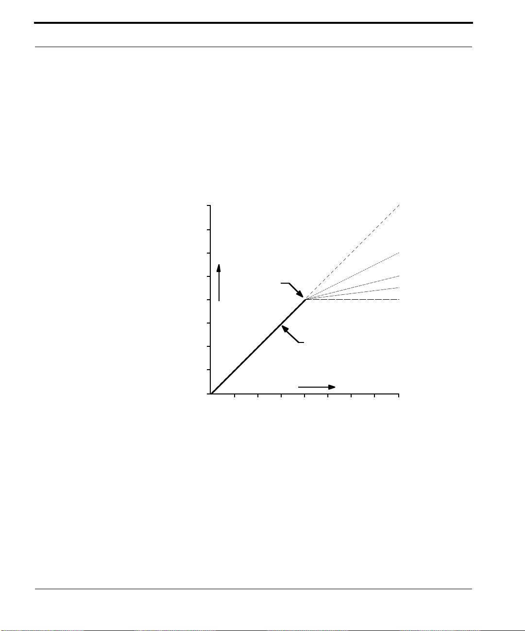
how much the dynamic range is compressed. Look at the illustration below.
compression ratio is
the measure of
1 to 1 r atio
2 to 1 r atio
THRESHOLD
OUTPUT LEVEL
Louder
I/O Curve
Louder
INPUT LEVEL
4 to 1 r atio
8 to 1 r atio
∞ to 1 ratio
This graph represents the relationship between the input level of the signal
and the output level of the signal after compression. Notice that the curve
has a breakpoint called a
threshold
. All standard compressors use a threshold. Signals that are louder than the threshold are processed (reduced in
level) while those softer than the threshold are unchanged.
As the input signal exceeds the threshold,
gain reduction
(reduction in loudness) is applied. The amount of gain reduction that is applied depends on
the compression ratio. The higher the compression ratio, the more gain
reduction is applied to the signal.
The graph shows the relationship between compression ratio and gain
reduction. Examine the 2 to 1 ratio curve. For signals above the threshold,
14
MDT UserÕs Manual
Understanding Compression
this curve transforms a range of loudness 2 units large into a range of loudness one unit large. Examine the ∞ to 1 curve. This curve transforms all
sounds above the threshold to the same loudness. Dynamics processors
which have this sort of curve are called limiters.
MDT As A Compressor
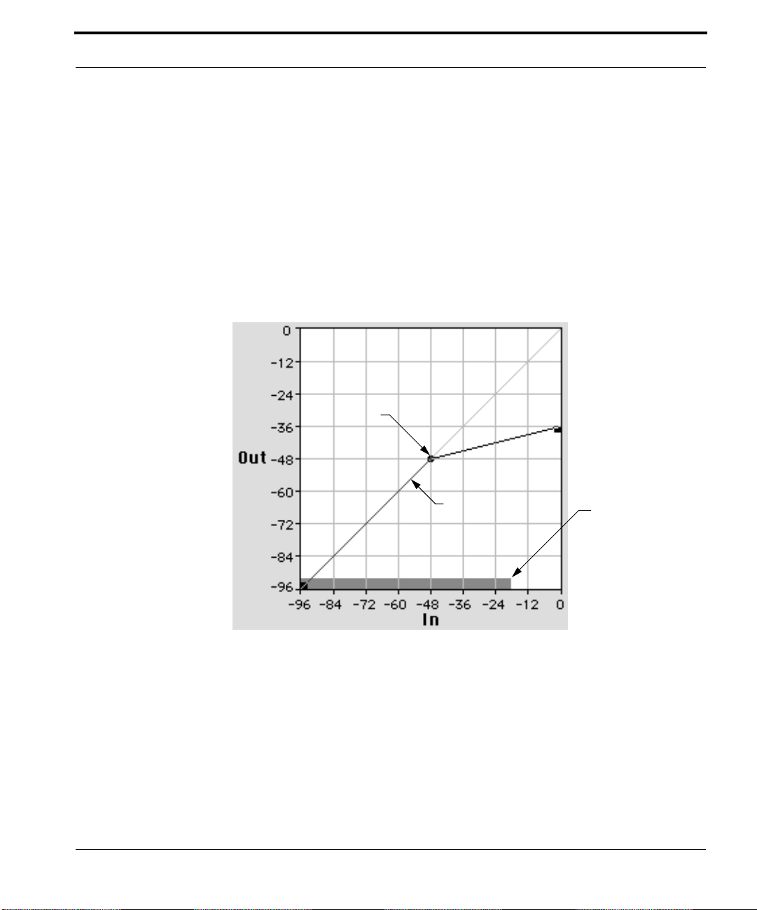
The graph described above appears in MDTÕs user interface. The following
illustration is a screen shot of MDTÕs In/Out Grid.
THRESHOLD
4 to1 Ratio
I/O Curve
Like the Þrst graph, this is a graph of the Input Level versus the Output
Level. The curve on the graph has a threshold and the curve segment above
the threshold has a 4 to 1 compression ratio.
The gray bar at the bottom of the graph is an input level meter. It shows
how loud the input signal is so that you can see where on the curve it falls.
In the illustration below, the input level is at -18 dB. The threshold is at
MDT UserÕs Manual
Input Level
15
Introducing MDT
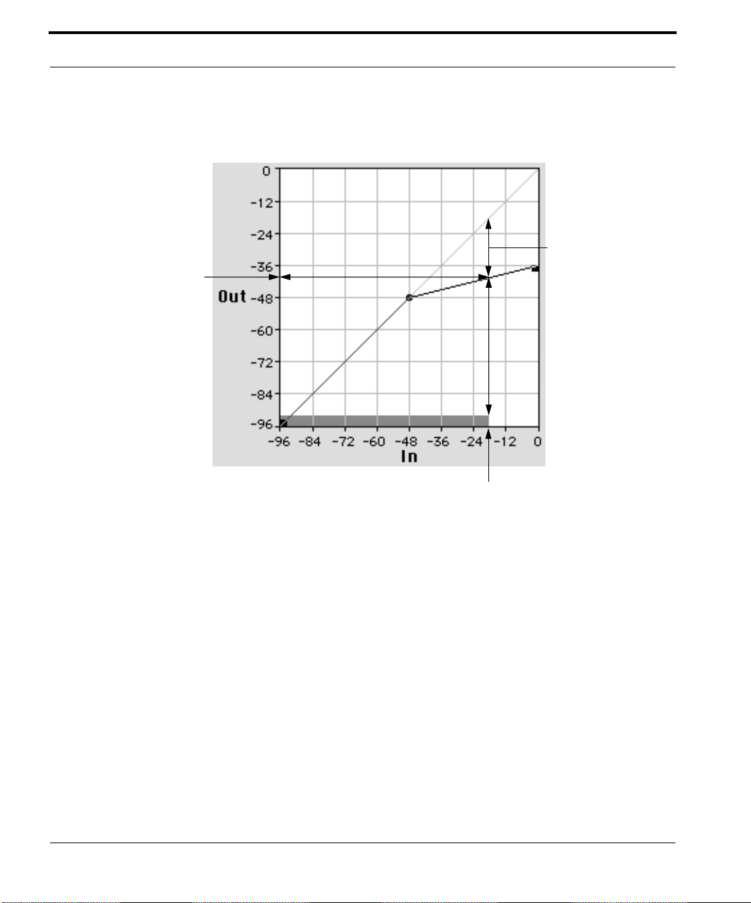
Output Level: -39 dB
-48 dB. The input is above the threshold so it is getting a gain reduction of
-21 dB. This puts the output at -39 dB.
Gain Reduction = 21 dB
4 to 1 Ratio
THRESHOLD = -48 dB
16
MDT UserÕs Manual
Input Level: -18 dB
The In/Out Grid
In conventional dynamics processors, there are knobs or sliders that control
the threshold and ratio parameters. MDT uses a graphic interface called the
In/Out Grid for these adjustments. The In/Out Grid provides visual feedback of the effect the tool is having on the sound. The complexity of the processorÕs conÞguration is easily controlled using multiple thresholds and
their associated compression ratios.
The details of how to use MDTÕs graphic interface are explained in Lesson 1
of the MDT Tutorial.
MDTÕs I/O Curve can be arranged to create many different kinds of
dynamic processing devices in addition to compressors. Many esoteric and
expensive outboard dynamics processors can also be emulated. The Setting
menu contains many settings which you will Þnd useful in creating ÒsweetÓ
sounding digital expanders, spectral enhancers, companders, and other
tools useful in mastering, tracking, and sound design. The examples below
Understanding Compression
explain some of the conÞgurations that are possible using MDTÕs unique
graphic interface.
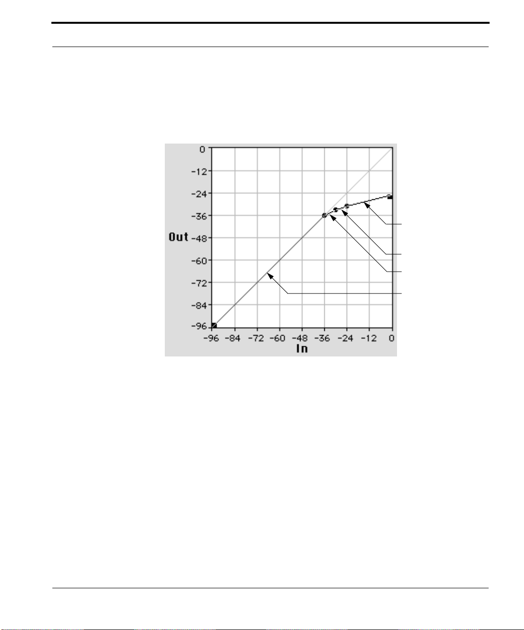
ÒSoft KneeÓ Compressor
Ratio = 4 to 1
Ratio = 3 to 1
Ratio = 2 to 1
Ratio = 1 to 1
ÒSoft kneeÓ compressors sound less obvious than regular Òhard kneeÓ compressors because the compression ratio near the threshold changes gradually. In the example above, as the signal gets louder than the threshold, it is
Þrst compressed at 2 to1. As it gets louder still, the ratio goes to 3 to1, until,
Þnally, it reaches its maximum ratio of 4 to 1. This setting sounds less
ÒsquashedÓ than a plain 4 to 1 hard knee compressor because only the
peaks in the signal get the full 4 to 1 compression.
The Òsoftest kneeÓ dynamics processors available are the tube-type compressors, especially the vintage variety. The following example shows how
MDT can be conÞgured to emulate a tube compander.
MDT UserÕs Manual 17
Introducing MDT
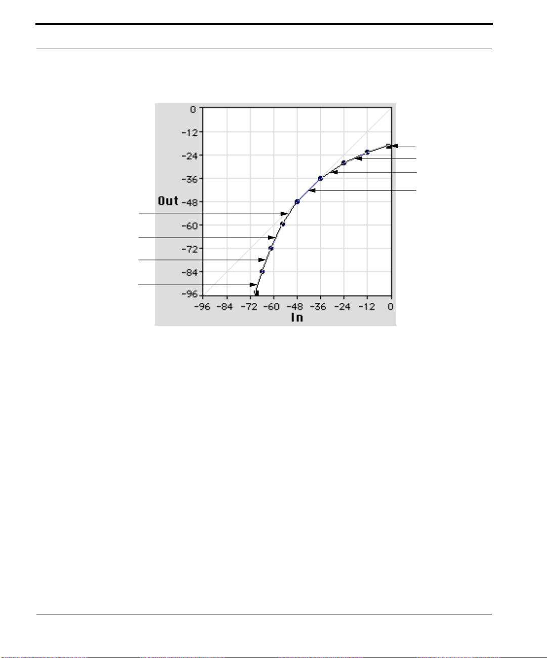
ÒTubeÓ Compander
Compression Ratios
3 to 1
2.2 to 1
1.5 to 1
Expansion Ratios
1 to 1.5
1 to 2.2
1 to 3.0
1 to 4.0
1 to 1
The curve shown above has no clear threshold point where the signal starts
to get processed. Instead, the compression or expansion ratios change gradually. It is called a compander because it both compresses and expands the
dynamic range, depending on the level of the input. The top half of the
curve compresses the dynamic range. The bottom half of the curve expands
the dynamic range.
The sonic effect of processing through this kind of setting is very natural.
Only the peaks of the sound get compressed heavily, while most of the signal passes through at a 1 to 1 ratio. This assumes that the average input
level is around -40 dB. (See ÒThe Input Offset ArrowsÓ on page 27 for an
explanation of how to ÒplaceÓ an input on the curve without actually
changing its level.)
18 MDT UserÕs Manual
Sounds quieter than -48 dB get expanded downward, that is, they are faded
down as they get softer. Because the curve increases in slope gradually, this
subtle gating effect sounds very natural. It is useful for eliminating noise
and maintaining a sense of wide dynamic range while still compressing the
hot peaks in the signal.
Understanding Compression
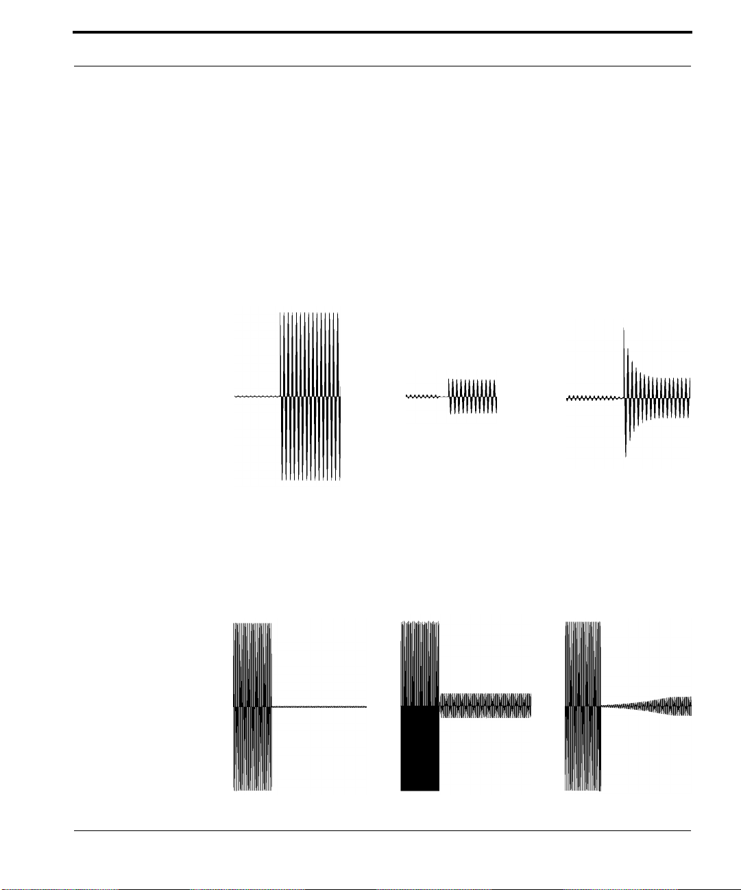
Attack And Release Times
The attack time of a compressor is simply how long it takes for the compressor to react once the input level has met or exceeded the threshold level.
With a fast attack time, the signal is brought under control almost immediately, whereas a slower attack time will allow the start of a transient or a
percussive sound to pass through uncompressed before the processor has
time to react. Creating a deliberate overshoot by setting an attack time of
several milliseconds is an effective way to emphasize the percussive nature
of instruments. The illustration below shows the effect of changing the
attack time.
Uncompressed Input CompressedCompressed
1 mSec attack 10 mSec attack
The release time of a compressor is the time it takes for the gain to return to
normal after the input level drops below the threshold. Setting too quick a
release time can cause a pumping effect in the output. If the release time is
too long, the compressor will not accurately track level changes in the
input. The illustration below shows the effect of changing the release time.
Uncompressed Input
Compressed
1 mSec release
Compressed
50 mSec release
MDT UserÕs Manual 19

Introducing MDT
MDT In The TDM Environment
The TDM software environment is supported by hardware from Digidesign
called the DSP Farm. Each DSP Farm card contains DSP chips on which
MDT and other DSP plug-ins run. The TDM system requires that one chip
on the DSP Farm be used for the Mixer plug-in which comes with ProTools.
Assigning a large number of ProTools voices will sometimes require the use
of two DSP chips on the DSP Farm.
MDT processes two audio channels per DSP chip. The table below shows
how many DSP chips are used as more MDT channels are allocated.
Number of MDTs used Number of DSP chips allocated
2 mono to mono MDTs 1
1 stereo to stereo MDT 1
1 mono to mono plus 1 stereo to stereo MDT 2
NOTE: Sometimes TDM will post a warning dialog saying that there are an
insufÞcient number of DSP chips available when you have added a normally legal number of MDTs. This is because of the order in which TDM
allocates the DSP chips as you add more inserts. If this occurs, de-assign a
MDT or two and then re-assign them. This allows TDM to sort out its DSP
allocation, allowing the greatest use of the available DSP chips.
20 MDT UserÕs Manual
CHAPTER 3 MDT Tutorial
ÒI donÕt want to know how it works Ð
I want to know how to work it!Ó
Ð Keith Emerson
This chapter is a step-by-step explanation of how to use MDT. MDT is a
breakthrough in technology and is therefore unique. If you follow these lessons one step at a time, you will master MDT and fully beneÞt from its
capabilities.
The whole tutorial takes about 90 minutes to complete.
Lesson 1: MDT Basics
In/Out Grid
I/O Curve
Peak Level Indicator
Input Offset Arrows
Input Offset Display
Input/Output Display
This lesson presents the elements of MDTÕs user interface.
MDT UserÕs Manual 21

MDT Tutorial
About DSP Plug-ins
DSP Plug-ins are software programs that run inside ProTools, and other
programs to add functionality and provide a variety of DSP tools. All TDM
compatible plug-ins have a few basic features in common. This section
describes those features.
1. Start ProTools and open the session named ÒMDT TutorialÓ.
2. Select ÒShow Inserts ViewÓ from the Display Menu.
3. Click on the MDT insert in the track labeled ÒAux 1Ó.
4. Choose Reset Settings from MDTÕs Setting menu.
5. In the Transport Window, click on the locator point labeled ÒShort VoiceÓ.
The Peak Level Indicator
1. Start playback with looping.
A Peak Level Indicator appears at the bottom of the In/Out Grid of
MDT. It displays the current input level that MDT uses to make gain
adjustments.
22 MDT UserÕs Manual
As the soundÞle plays, notice the dynamic range that the Peak Level
Indicator covers.
MDT uses look-ahead peak averaging to determine the loudness of a
sound. Look-ahead peak averaging means MDT scans the data about to be
processed for upcoming peaks while calculating the average peak level of
the data itÕs currently working on. It uses both numbers to derive the Þnal
input level. MDT can scan up to 1024 samples ahead, depending on the DSP
card being used.
2. Use the mouse to press on the right arrow of the Release slider. Increase the
release time to 4,999 mS (milliseconds).
Notice that, as the release time increases, the Peak Level IndicatorÕs
movement slows down and the displayed signal level gets higher on the
IN scale. This is because, as the release time increases, it takes longer for
hot peaks to be averaged out of the level calculation. The actual signal
Press here to increase
the Release time
Upper T erminator
Lesson 1: MDT Basics
may be ßuctuating wildly, but the displayed level will always be the
average value of the peaks inside the time window determined by the
Attack and Release settings.
3. Drag the Release slider to the far left position. Notice the change in the Peak Level
Indicator.
With a release time of 0 milliseconds, the Peak Level Indicator more
closely reßects the actual instantaneous sound level.
4. Stop playback.
5. Reset MDT by choosing Reset Settings from the Setting menu.
The I/O Curve
MDT uses a unique graphic interface to describe the relationship between
Input and Output levels. This relationship is called the transfer characteristic
or, in MDT parlance, the I/O Curve. This section demonstrates the manipulation of the I/O Curve.
Threshold
I/O Curve
In/Out Grid
Lower Terminator
In/Out Display
NOTE: Points on the I/O Curve or the In/Out Grid will always be written
as a pair of negative numbers, e. g. -60:-60. The Þrst number is the location
MDT UserÕs Manual 23

MDT Tutorial
of the point on the In coordinate of the In/Out Grid. The second is equal to
its Out value on the Grid.
1. Move your mouse cursor into the In/Out Grid.
The cursor changes into the cross cursor shape.
2. Click and drag the mouse inside the Grid.
A threshold appears in the I/O Curve. As you move the threshold
around the Grid, the I/O Curve Òrubber bandsÓ to follow the movements of the cursor. Notice that the threshold location is displayed in the
In/Out Display. Also notice that the In/Out Display shows the angle of
the two moving line segments expressed as the ratio of the Input to the
Output.
3. Release the mouse.
The threshold remains at the release point. It is now highlighted as
shown in the illustration above.
4. Move the threshold to In/Out coordinates -60:-60 by placing the cursor over the
threshold and dragging it to the new location.
24 MDT UserÕs Manual
5. Place the cursor over the lower terminator (the small square object in the lower
left corner of the In/Out Grid) and drag it to the right to -60.5:-96.
Notice that the lower terminator is ÒgluedÓ to the In axis. It will always
have an Out value of -96 dB. The In/Out Display shows the ratio of the
moving curve segment. As you drag the lower terminator to the right,
notice that it cannot go past the threshold at -60:-60. This is to prevent
the I/O Curve from having more than one output value for any given
input value.
6. Drag the upper terminator (in the upper right corner of the In/Out Grid) to 0:-48.
The upper terminator is glued to the Out axis. It will always have an In
value of 0dB. During the drag, the In/Out Display shows the ratio of the
moving curve segment.
7. Add a second threshold by clicking the cursor at -24:-24.
While positioning this threshold, notice that the In/Out Display is displaying the positive going curve on the left as an N to 1 ratio, and the
negative going curve on the right as a -N to 1 ratio. It is possible to use
MDT to create inverse gain functions.

Threshold at -24:-24
Upper terminator at 0:-48
Threshold at -60:-60
Lower terminator at -60.5:-96
Lesson 1: MDT Basics
At this point in the exercise, MDT should look like this:
8. Delete the thresholds by pressing <option> and clicking on the thresholds.
The thresholds disappear and the curve snaps to its new position automatically.
9. Reset MDT by choosing Reset Settings from the Setting: menu.
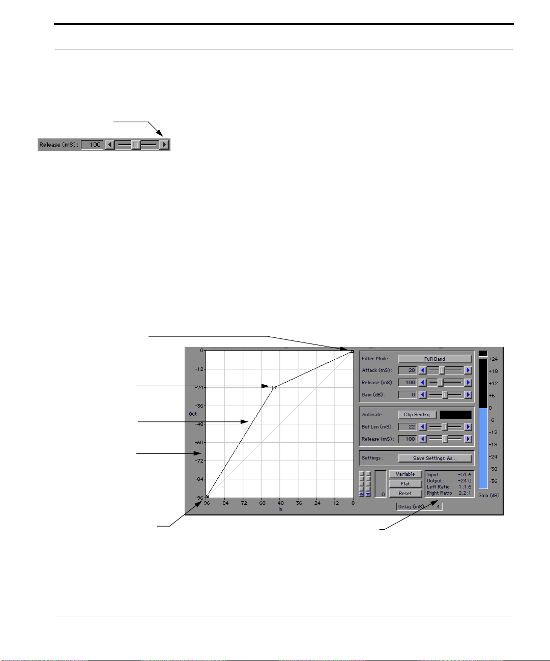
The In/Out Grid
MDT works by detecting the level of the input signal, looking for the point
on the I/O Curve with that input value, and then adjusting the gain so that
the output level equals that of the I/O Curve at that point.
All the possible points where the I/O Curve can exist are represented by the
In/Out Grid. It is divided by a diagonal line that represents the points on
the Grid that have input levels equal to output levels (e.g. -48:-48). Placing
the I/O Curve on this diagonal will cause MDT to output the signal at the
same level as it was input.
The points on the Grid which have output levels lower than their input levels (e.g. -48:-72) are located below the diagonal. Placing the I/O Curve
below the diagonal will cause MDT to output the signal at a lower level
than it was input (gain reduction).
MDT UserÕs Manual 25

MDT Tutorial
-72:-48
-48:-48
-48:-72
Points on the Grid which have output levels higher than their input levels
(e.g. -72:-48) are located above the diagonal. Placing the I/O Curve above
the diagonal will cause MDT to output the signal at a higher level than it
was input (gain ampliÞcation).
The following section demonstrates the relationship between I/O Curve
position and gain.
26 MDT UserÕs Manual
1. Choose 1:1, -12 dB gain from the Settings menu.
2. Start playback with looping.
The voice is heard 12 dB lower in volume because the I/O Curve shifts
every point on the In axis -12dB on the Out axis.
3. Adjust the Gain slider to read 12 dB.
4. Click the Bypass button on and off to verify the level match.
The processed level is now precisely the same as the original level
because of the additional gain supplied by the Gain slider. The gain factor set into the Gain slider is applied after the signal is processed by the
I/O Curve and is the last stage of control in MDT.
5. Choose 1:1, -24 dB gain from the Settings menu.
The voice is heard 12 dB lower in volume because the I/O Curve has
shifted everything an additional -12 dB lower on the Out axis.
6. Adjust the Gain slider to read -12 dB.

Lesson 1: MDT Basics
7. Choose 1:1, +12 dB gain from the Settings menu.
The voice is now heard at the original volume level. The I/O Curve is
amplifying it by 12 dB and the Gain slider is reducing the gain by -12 dB.
Use the Bypass button to verify this.
8. Stop playback.
9. Choose Reset Settings from the Settings menu.
The Input Offset Arrows
Input Offset is another unique feature of MDT. The Input Offset Arrows
(see illustration) allow you to change the relationship of the input signal to
the I/O Curve without actually changing the signal level of the input data.
Input Offset Arrows
In a single band conÞguration, the placement of the thresholds can be
tweaked using the Input Offset without disturbing the I/O Curve. In multiband conÞgurations, spectral bands can be independently adjusted. By
adjusting the different bands to the same level, coloration is reduced.
Adjusting the different bands to completely separate sections of the I/O
Curve allows independent compression ratios and levels for each band.
These multiband cases will be demonstrated later.
1. Choose Input Offset Test from the Settings menu.
Input Offset Display
MDT UserÕs Manual 27

MDT Tutorial
2. Start playback with looping.
3. Press and hold down the downward Input Offset Arrow.
As the Peak Level Indicator moves to the left, notice that the loudness of
the playback remains the same. This is because the input data is not
being changed. Only its relationship to the I/O Curve is being changed.
When the Peak Level Indicator moves through the region between -36
dB and -60 dB on the Input scale, notice that the loudness of the sound
decreases by 36 dB. This is because the I/O Curve is set for a -36 dB gain
reduction in that region. As the Peak Level Indicator moves below -60
dB, the output goes back to normal because the I/O Curve is back at
unity gain (0 dB gain).
The Input Offset Arrows always increment in 1 dB steps. Press <option>
then press on the arrows slows the rate of change.
4. Press on the upward Input Offset Arrow until the reading returns to 0.
The value displayed in the Input Offset Display (see illustration) is the
difference in dB between the actual input level and the displayed level.
5. Stop playback.
28 MDT UserÕs Manual
6. Choose Reset Settings from the Settings menu.
The Setting Menu
MDT has a Setting menu which allows you to store your most used MDT
set-ups and instantly recall them. The Setting menu allows an unlimited
number of ÒsnapshotsÓ of MDTÕs settings to be saved. This data is saved in
the ÒMDT PreferencesÓ Þle in the SystemÕs ÒPreferencesÓ folder. In this section you will learn how to save, recall, and delete settings from the Setting
menu.
1. Put four thresholds on the I/O Grid at In:Out = -12:-48, -24:-12, -36:-48, and -48:-12.
2. Choose 5 band AP from the Filter Mode menu.
3. Increase the Attack time to 50 mS.
4. Increase the Release time to 4,999 mS.
5. Decrease Gain to -24 dB.

6. Decrease the Low Band Input Offset to -15.
At this point MDT should look like this:
To save these settings,
Lesson 1: MDT Basics
1. Choose Save Settings AsÉ from the Setting menu.
A dialog box appears requesting a setting name.
2. Type Test in the text box and click on Save.
The settings are now saved under the name ÒTestÓ. These settings
appear at the bottom of the Setting menu.
3. Choose Reset Settings from the Setting menu to revert to the default values.
To recall the setting;
1. Choose Test from the Setting menu.
The settings are recalled as you saved them.
To delete the setting;
1. Choose Delete SettingsÉ from the Setting menu.
A dialog appears with the list of the settings in the menu.
2. Scroll down to Test and select it by clicking on it.
3. Click on the Delete button.
MDT UserÕs Manual 29

MDT Tutorial
The setting is deleted from the menu. You may select multiple settings
for deletion by shift-clicking or click dragging over the items to be
deleted. To make a non-contiguous selection, press <command> and
click on the items to select them. Note that the settings themselves
remain on MDT until you move them yourself or choose another setting.
Lesson 2: Single Band Applications
The following section demonstrates how to conÞgure MDT as a single band
compressor, limiter, gate, expander, Òsoft kneeÓ compressor/gate, and
ÒtubeÓ compander.
Compressor
1. Select the ÒFetes 1Ó soundÞle for playback.
2. Click on the MDT insert in the track labeled ÒAux 1Ó.
30 MDT UserÕs Manual
3. Choose Reset Settings from the Setting menu.
4. Start playback with looping.
The selection is an excerpt from Fetes (rhymes with ÒpetÓ), the second of
DebussyÕs Nocturnes for orchestra. Notice the relative loudness of the
brass notes compared to the quiet strings that follow. The Peak Level
Indicator shows an approximate dynamic range of -24 dB.
5. Choose 3:1, -48 dB threshold from the Settings menu.
Notice the shape of the I/O Curve. Sounds that have input levels lower
than -48 dB are in a 1 to 1 relationship with the output. Above -48 dB, the
signal will get a different gain reduction depending on its input level.
For example, a sound input at -12 dB will get a -24 dB gain reduction and
be output at -36 dB. A sound at -24 dB input will only get a -16 dB gain
reduction and be output at -40 dB, and so on. A piece of music with a
dynamic range from -12 dB to -36 dB (a 24 dB dynamic range) would be
output from -36 dB to -44 dB (an 8 dB dynamic range). Shrinking 24 dB
down to 8 dB is a 3 to 1 compression ratio.

Lesson 2: Single Band Applications
-24 dB gain
-16 dB gain
The Gain slider is set at 18 dB to compensate for the gain reduction of the
compressor. The loudest sounds will come out at approximately the
same level as before compression.
Notice how the quiet string passage is now louder than before. The brass
remains at its previous level.
6. Use the Bypass button to compare the original with the compressed signal. Deactivate Bypass when youÕre done.
7. Change the compression ratio to 4 to 1 by dragging the upper terminator down
until the Left Ratio Þeld in the I/O Display equals 4:1.
The compression ratio approaches ∞ to 1 as the I/O Curve approaches
the horizontal. At a ratio of ∞ to 1, all sounds above the threshold would
be output at the same level.
8. Stop playback.
Attack and Release Times
The time it takes for MDT to react to an incoming peak is controlled by the
Attack Time. The Release Time determines how fast the input level will
return to its quiescent state after the peak comes through. The following
section is a demonstration of the effect that Attack and Release times have
on the sound.
MDT UserÕs Manual 31

MDT Tutorial
A four unit change in
the input gives a one
unit change on the
output.
1
4
MDT should now be adjusted to a 4 to 1 compression ratio from the last section. If it isnÕt, please do this now.
1. Select the ÒpluckÓ soundÞle for playback.
2. Reduce the Gain setting to 14.
3. Start playback with looping.
4. Use the Bypass button to compare the original with the compressed signal. Deactivate Bypass when youÕre done.
The region, ÒPluckÓ, is a loud violin section pizzicato with a reverb tail.
Notice how the compression exaggerates the reverb and the noise in the
sample. Notice the ÒshapeÓ of the reverb tail and its decay time. Also
notice the body of the attack portion of the sample.
5. Reduce the Attack time to 0 mS.
32 MDT UserÕs Manual
The initial attack is now compressed. MDT reacts immediately to change
the gain so that the attack is output at a much lower level.
6. Press on the right arrow of the Attack slider. Notice the change in the body of the
sound as the Attack time increases.
At 50 mS, the attack is much louder than the sustained portion of the
ÒPluckÓ. Changing the Attack time lets you tailor the aggressiveness of
the attack to your needs.
7. Return the Attack setting to 20 mS.

Lesson 2: Single Band Applications
8. Increase the Release setting to about 5,000 mS.
Notice how the reverb tail sounds almost exactly like the uncompressed
version. This is because the Release time is much longer than the reverb
time. The shape of the reverb tail is not effected because the detected
input level (as shown by the Peak Level Indicator) decays very slowly
when the Release time is this long.
This slow release time has an additional effect. Since the peak input level
is high, the gain reduction of the output signal is also high, causing it to
play back more softly than before. The Gain slider can be adjusted to
compensate for this effect.
9. Decrease the Release time to about 300 mS.
At this setting, the rate of change in output gain is approximately equal
to the reverb decay rate. The result sounds like a smooth decay with the
reverb compressed.
10. Stop playback.
MDT UserÕs Manual 33

MDT Tutorial
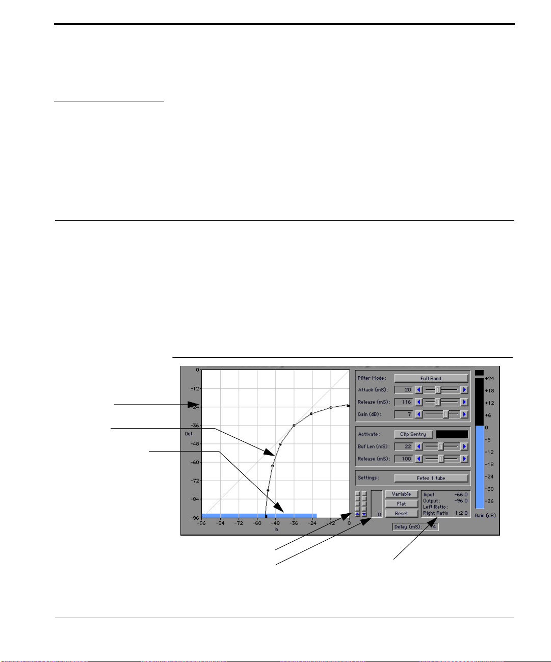
Expander/Gate
MDT can be used as an expander/gate to eliminate noise and for creating
gated effects. This section demonstrates how to use the I/O Curve to conÞgure a downward expanding gate.
1. Choose 1:1, -36 dB gate from the Settings menu.
34 MDT UserÕs Manual
1. Start playback with looping.
As the reverb decays below the -36 dB threshold, the output gain
changes to -60 dB, gating the sound off.
2. Press <option> and then the downward Input Offset Arrow until the display
reads -15.
The reverb tail is now gated off sooner because the input level reaches
the -36 dB threshold sooner. The Input Offset Adjust Arrows can be used
in conjunction with the Release time slider to get exactly the gate time
you wish.

1 to 2.0 expansion ratio
Lesson 2: Single Band Applications
3. Move the lower terminator to the left until the value displayed in the I/O Display
equals 1:2.0.
The reverb now decays evenly because the output gain tapers gradually
below the -36 dB threshold.
4. Stop playback.
Example 2: Compressor with Noise Gate
1. Select the ÒShort VoiceÓ soundÞle for playback.
2. Choose 3:1, -48 dB threshold from MDTÕs Settings menu.
3. Start playback with looping.
Notice that the region has a high noise ßoor. The noise level is just below
the -48 dB threshold.
4. Drag the lower terminator to the right as far as it will go.
You will hear that the noise is gated out for the most part. There is still a
small noise just after the words ÒÉSound Designer IIÉ(noise)Ó.
5. Decrease the Gain setting to 9 dB.
6. Press <option> and then the downward Input Offset Arrow until the display
reads -15.
MDT UserÕs Manual 35

MDT Tutorial
The noise is virtually eliminated because the input signal has been
shifted down in relationship to the gating threshold. The noise now
gates off immediately.
7. Stop playback.
ÒTubeÓ Compander
Many complex signals like full mixes and vocals require a high degree of
dynamic control, but suffer from the effects of heavy compression or limiting. The use of a Òsoft kneeÓ compressor or Òtube-likeÓ compander can
make the effects of strong compression less obvious. A Òsoft kneeÓ compressor is characterized by having a gradual change in compression ratio at
its threshold. A ÒtubeÓ compander has a continuously varying compression
ratio over the range of the input.
Example 1: ÒSoft KneeÓ comp/gate
1. Choose Òsoft kneeÓ 4:1 -36 dB from the Settings menu.
36 MDT UserÕs Manual
2. Start playback with looping.
Compare this sound with the previous example. The voice sounds less
ÒsquashedÓ even though the compression ratio is higher because the
change in ratio at the threshold is less abrupt.
3. Stop playback.

Lesson 2: Single Band Applications
Example 2: ÒtubeÓ comp/gate
1. Choose ÒtubeÓ comp/gate from the Settings menu.
2. Start playback with looping.
Contrast the sound of the voice with the previous two settings. The
vocal sound is even more natural because, most of the time, it is sitting
on an area of the I/O Curve which has relatively small compression/expansion ratios. Only the peaks or valleys of the signal are
effected by the high ratio segments of the I/O Curve.
The reason ÒtubeÓ companders work so well for complex signals is
because the compression/expansion ratio changes gradually from some
central operating point Ð in this case, -36 dB, making the effects of compression less audible. Normal compressors maintain the same ratio over
a wide dynamic range.
3. Stop playback.
MDT UserÕs Manual 37

MDT Tutorial
Example 3: Full mix
1. Select the ÒFetes 1Ó soundÞle for playback.
2. Select the Fetes 1 tube from the settings menu.
3. Start playback with looping.
38 MDT UserÕs Manual
The ratios of the downward expander part of the curve have been
relaxed in this setting to accommodate the lower level and dynamic
range of this excerpt. Compare the sound of this setting with the sound
of the 3:1, -48 threshold setting that you used above.
4. Use the Bypass button to compare the original with the compressed signal. Deactivate Bypass when youÕre done.
5. Stop playback.
Lesson 3: Multiband Applications
Lesson 3: Multiband Applications
In this lesson, you will learn how to use MDT in multiband mode. This
capability of MDT makes it the most powerful and ßexible dynamics processing tool available.
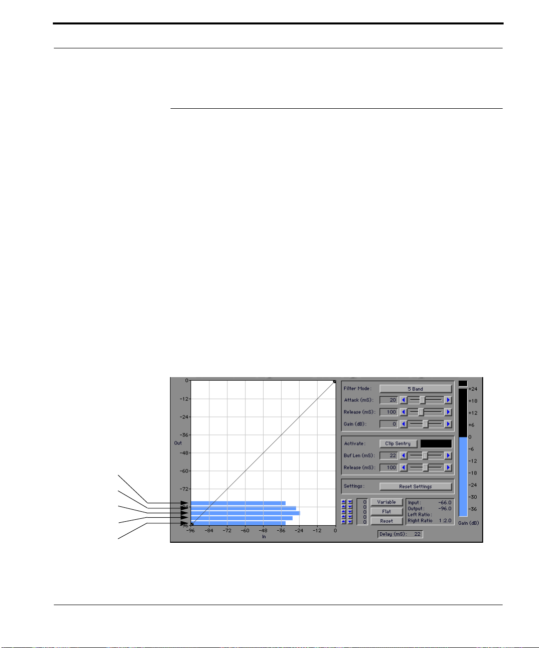
Multiband Peak Level Indicators
In multiband mode, MDT divides the energy of the signal into three or Þve
equally spaced bands. The peak level of each band is displayed by its own
Peak Level Indicator at the bottom of the In/Out Grid.
1. Select the ÒShort VoiceÓ soundÞle for playback.
2. Select 3 band from the Filter Mode menu.
3. Start playback with looping.
The Peak Level Indicators display the level of each band. The three
bands (High, Mid, Low) are shown in that order, the Low band being at
the bottom of the In/Out Grid. Each band is 3.3 octaves wide and has its
own Input Offset Arrows.
High Band
High Mid Band
Mid Band
Low Mid Band
Low Band
4. Select 5 band from the Filter Mode menu.
In 5 band mode, Þve Peak Level Indicators are shown - High, Hi-Mid,
Mid, Low-Mid, and Low. Each band is 2 octaves wide.
MDT UserÕs Manual 39
MDT Tutorial
The Filter Modes
MDT uses digital Þlters to separate the energy of the input signal into multiple bands. These Þlters have particular characteristics which need to be
understood to use MDT most effectively.
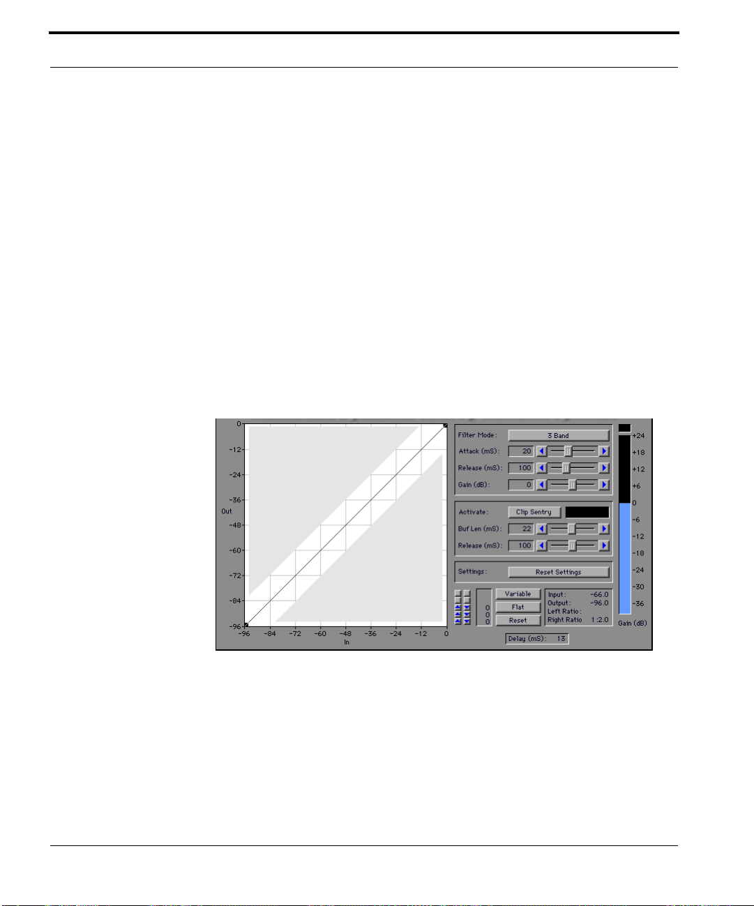
In the 3 Band mode and 5 Band mode, with the I/O curve along the diagonal line, MDT responds like an equalizer with gain levels set ßat. This
means there are +/- 1dB variations in amplitude as a function of frequency.
3 Band AP and 5 Band AP works differently, so that the output is identically
equal to the input, and the Þlters only become involved when the gain
curve is not on the diagonal.
Why not use the AP mode all the time? The AP mode Þlters have a limited
gain reduction range of -12 dB. This means that the input signal can't be
attenuated more than 12 dB. In cases where more gain reduction is needed,
the non-AP versions will give the best result.
Placing the I/O Curve in
the shaded parts of the Grid will
cause unpredictable
changes in the tonal
balance when using AP
mode filters.
40 MDT UserÕs Manual
Multiband Compressor
There are many times when it is necessary to compress a complete mix.
Often, especially when compressing at a high ratio, ÒpumpingÓ can occur.
This is when one sound or group of sounds in the mix is modulating the

Lesson 3: Multiband Applications
loudness of the other sounds. The following example demonstrates the use
of a multiband compressor to alleviate the pumping problem.
1. Select the ÒBass SoloÓ soundÞle for playback.
2. Choose Pumping 1 band in the Setting menu.
The compression ratio above the threshold is 10 to 1.
3. Start playback with looping.
Notice how the loudness of the cymbal and sustained pad is ÒpumpedÓ
by the bass solo.
4. Choose Better 5 band in the Setting menu.
This setting is the same as before except for the use of multiband mode.
Notice how the pumping effect is greatly reduced.
Extreme settings are used in the example so as to create pumping in the output for the purposes of illustration. In a real world application, with a more
moderate compression ratio and release time, the multiband compressor
would provide even better results.
MDT UserÕs Manual 41

MDT Tutorial
Managing Tonal Balance In Multiband Mode
What is the Tonal Balance Problem?
You may have noticed in the previous exercises that the multiband Peak
Level Indicators almost never have the same simultaneous level. This is
because the energy distribution across the spectrum changes from moment
to moment. Since all the bands are using the same I/O Curve, each band
may receive a different gain depending on its current level and placement
on the I/O Curve. The following example demonstrates this behavior.
1. Select the ÒShort VoiceÓ soundÞle for playback.
2. Choose 3:1, -48 dB threshold in the Setting menu.
3. Start playback with looping.
Listen for the tonal balance of the voice.
4. Choose 3 Band in the Filter Mode menu.
42 MDT UserÕs Manual
-15 dB
-8 dB
Notice how the tonal balance is brighter. The highs are accentuated
because the average level of the High band is about 5 dB lower than the
other bands. This means that it is getting less gain reduction than the
other bands and is therefore ÒhotterÓ in relation to them.
5. Stop playback.

Offsetting the inputs
so that they are about
equal insures that all
the bands receive the
same gain.
Lesson 3: Multiband Applications
How To Achieve Tonal Balance
It is often desirable to preserve the soundÞleÕs original tonal balance while
beneÞting from using multiband mode. The key element in preserving
tonal balance is having each band get the same amount of gain at the same
time. You can do this by offsetting the input level of the ÒhotterÓ bands to
equal the lowest level band. The following exercise demonstrates two different ways to achieve this.
1. Start playback with looping.
2. Press and hold the ÒFlatÓ button for about 2 seconds.
The Input Offset values for each band are automatically adjusted so that
they have equal amounts of gain reduction over the period of time the
Flat button is held down. That is, the Input Offset values are adjusted so
that the bands receive, on the average, equal amounts of gain reduction
as measured over the period the button is held down. This technique is
applicable when the natural tonal coloration of the sound does not vary,
as is the case with a single speakerÕs voice.
3. Choose Full Band in the Filter Mode menu.
Notice how the 1 band tonal balance closely matches the tonal balance of
the adjusted 3 band sound.
4. Click on the ÒResetÓ button to zero the Input Offset values.
5. Click on the ÒVariableÓ button.
MDT UserÕs Manual 43

MDT Tutorial
The Input Offset values now change continuously, in an ongoing effort
to achieve equal amounts of gain reduction. The amount of gain reduction is measured over a period of time equal to three times the compressor release time. In this way, the separate bands can respond
individually to what is occurring in the sound, but at the same time, they
are being drawn towards one-another to preserve the original tone color.
Using the ÒVariableÓ button will preserve the original tone color of
sounds having variable tone color. The ÒFetesÓ and the ÒBass SoloÓ are
good examples of this.
6. Stop playback.
IMPORTANT:
The ÒVariableÓ button requires CPU processing to work. MDT does this processing when it is given control of the CPU to update meters. MDT is not
given the CPU when the plugin is not visible. Hence, the ÒVariableÓ button
will not work when the plugin is not visible. In order to achieve the effect of
the ÒVariableÓ button when the plugin is not visible, you must record the
resulting input offset level changes using automation in ProTools 4.
44 MDT UserÕs Manual

Lesson 3: Multiband Applications
MDT As A Spectral Enhancer
The tonal ßexibility demonstrated above can be used to modify the existing
tonal balance dynamically. De-essers, spectral enhancers, and dynamic EQs
all modify the tonal balance dynamically. This example below shows how
to use MDT to perform these functions.
De-esser
1. Select the ÒShort VoiceÓ soundÞle for playback.
2. Choose 6:1 de-esser in the Setting menu.
The compression ratio above the threshold is 6 to 1. Notice how the I/O
Curve straddles the diagonal. Sounds above the threshold and to the left
of the diagonal get ampliÞed. Sounds to the right of the diagonal receive
gain reduction.
3. Start playback with looping.
Notice how the High band is effected by compression and the other
bands are offset so they get no compression.
4. Use the Bypass button to compare the original with the compressed signal.
MDT UserÕs Manual 45

MDT Tutorial
5. Press the High band's downward Input Offset Arrow until the display reads -14.
The High band peaks will occur at approximately the 0 dB gain line (the
diagonal). This setting should sound very similar in tonal balance to the
original. Any high frequency peaks will be compressed at a 6 to 1 ratio.
Spectral Enhancer
1. Press the High band's downward Input Offset Arrow until the display reads -20.
46 MDT UserÕs Manual
The High band peaks are now occurring in the area of the I/O Curve to
the left of the diagonal. The sound is brighter because the highs are getting ampliÞed while still being compressed at a 6 to 1 ratio.
2. Experiment with changing the tonal balance by moving the other bands into the
compression segment of the I/O Curve.
3. Use the Bypass button to compare the original with the enhanced signal.
4. Stop playback.
With the current setting of the I/O Curve, the louder a band gets, the more
gain reduction it receives. The next example shows how to conÞgure MDT
as a dynamic EQ.

1 to 1.5 expansion ratio
Lesson 3: Multiband Applications
Dynamic EQ
A dynamic EQ is a device that changes the amount of equalization it
applies as a function of input level or some other changing parameter of the
signal. MDT can be conÞgured as a dynamic EQ as shown below.
1. Select the ÒFetes 1Ó soundÞle for playback.
2. Choose High Freq. Expander in the Setting menu.
The expansion ratio above the threshold is 1 to 1.5.
3. Start playback with looping.
Notice how the High and Hi Mid bands are effected by expansion and
the other bands are offset so they get no expansion. The louder the
input signal, the greater the ampliÞcation of the highs.
4. Use the Bypass button to compare the original with the enhanced signal.
5. Experiment with changing the brightness of the sound by changing the offset of
the High and Hi Mid bands.
The effect can range from subtle to gross depending on the ratio of the
I/O Curve and the position of the band on the curve.
6. Stop playback.
MDT UserÕs Manual 47

MDT Tutorial
Lesson 4: Clip Sentry
This lesson will step you through how to use Clip Sentry.
Because MDT simulates the smooth sound of analog compressors, it is easy
to create data that exceeds to +1,-1 digital range. This is because of the
behavior of the Attack Time slider, which allows you to control the rate of
gain reduction due to a sudden increase in sound level. As in the analog
world, even a fast attack time will let through a faster transient. Since most
users jack-up the output gain to compensate for compression, these fast
transients almost always result in clipped data.
Clip Sentry is a high speed digital limiter designed to prevent clipping by
reducing gain only when clipping is about it occur.
1. Select the ÒShort VoiceÓ soundÞle for playback.
2. Choose ÒReset SettingsÓ from the settings menu.
3. Start playback with looping.
48 MDT UserÕs Manual
Notice how the gain reduction meter does not move. This is because the
I/O Curve is along the diagonal line. Hence no gain reduction is prescribed.
4. Increase the ÒGain (dB)Ó until the clipping begins to occur.
You can tell when clipping occurs because the clip light above the gain
reduction meter ßashes red.
5. Click the ÒClip SentryÓ button in.
You will now see that gain reduction occurs when clipping used to
occur. Also, notice that additional processing delay has been inserted
into the signal path.
6. Reduce the amount of delay to 5 mSec by changing the Clip Sentry Buf Len.
The Clip Sentry Buf Len causes less delay to occur for processing but it
also causes the gain reduction to occur more quickly. Depending on the
source material, shortening the delay will eventually cause objectionable
distortion.
7. Gradually decrease the Clip Sentry Release time.

Lesson 5: Using Automation
This causes the gain reduction to recover more quickly. Be careful,
though. If the gain reduction recovers too quickly, data in the Clip Sentry
buffer may cause superÞcial clipping to occur. A release time of 100
rarely produces clipping.
8. Stop playback.
If a large gain reduction occurs, a very short release will be less audible, but
may sound unnatural. A longer release time will be more audible. The
Release (mS) slider controls how rapidly the gain is allowed to change.
Hence, you have the Release Slider set to 1000 and rapidly increase the Gain
Slider, you will Þnd the actual output gain shows by the gain reduction
meter will increase slowly.
With Clip Sentry, if youÕre doing Rock-n-Roll, you can push it to the wall. If
you have big Þnal gain, short Buf Len (mS) and short Release (mS), you can
make a REALLY loud piece. Just listen carefully for distortion: You will be
creating more distortion from the fast gain change of a short Buf Len (mS)
than the occasional slight clip from the short Release (mS).
Lesson 5: Using Automation
ProTools version 4.0 introduces Automation for plugin controls.
All buttons and sliders (except for the ÒVariableÓ, ÒFlatÓ and ÒResetÓ buttons) have been automated when used with ProTools 4.0. Note that the
ÒVariableÓ, ÒFlatÓ and ÒResetÓ buttons control the Input Offset Levels,
which are automated. Hence, you can automate the effects of the ÒVariableÓ, ÒFlatÓ and ÒResetÓ buttons by using them when the input offset levels' automation is recorded.
The MDT Settings menu is also automated. Care must be taken, however,
not to automate ÒSave Setting As...Ó or ÒDelete Setting...Ó because these dialogs will be posted when automation plays back. Moving points in the I/O
Graph cannot be automated, although changing sets of points can be
recalled with the Settings Menu automation.
This lesson steps you through how to use automate the effects of the ÒVariableÓ button (a very important tool for preserving tone color).
MDT UserÕs Manual 49

MDT Tutorial
1. Select the ÒShort VoiceÓ soundÞle for playback.
2. Choose 3:1, -48 dB threshold in the Setting menu.
3. Select Ò5 BandÓ from the Filter Mode menu.
4. Enable the Input Offset arrows for automation.
In ProTools 4, click the ÒautomationÓ button in the plugin window and
ÒAddÓ the controls ÒLevel4Ó, ÒLevel3Ó, ÒLevel2Ó, ÒLevel1Ó and
ÒLevel0Ó. After clicking the ÒOKÓ button, the Input Offset Arrows will
be hilited Green. Next change the trackÕs Òauto readÓ to Òauto touchÓ.
5. Click the ÒVariableÓ button in.
6. Start playback with NO looping.
Playback will end after ÒShort VoiceÓ plays through.
7. Click the ÒVariableÓ button out and change Òauto touchÓ to Òauto readÓ.
8. Start playback.
You will see that the Input Offset Arrow changes were recorded and that
playback automation resulted from the ÒVariableÓ button having been
pushed during recording.
50 MDT UserÕs Manual
9. Stop playback.

Lesson 5: Using Automation
New Possibilities
You have probably thought of numerous applications for MDT that have
not been mentioned in the Tutorial. We hope that you have learned enough
about whatÕs possible with MDT that you feel free to experiment and create
ways to use it that are far beyond anything we expected.
Here is something to play with as a starting point that could produce
unique results in a sound design application.
Inverted Gain Curves
In the region effected by the inversion, increasing input level decreases the
output. Try out the Inverse Pluck setting with the ÒpluckÓ soundÞle.
MDT UserÕs Manual 51

MDT Tutorial
52 MDT UserÕs Manual

CHAPTER 4 MDT Reference
This chapter explains the detailed operation of every aspect of MDTÕs user
interface. The items are organized in alphabetical order to make them easy
to locate.
Attack Slider
The Attack slider controls the amount of time it takes for MDT to react to an
incoming peak. The range of the control is from 0 milliseconds to 50 milliseconds. The current attack time is displayed in the window to the left of
the slider.
Clicking on the arrows decrements/increments the attack time by one millisecond. Pressing on the arrows decrements/increments the attack time continuously. Press <option> to slow the speed at which the value increments.
The thumb wheel can be dragged for making gross adjustments.
Automation
All buttons and sliders (except for the ÒVariableÓ, ÒFlatÓ and ÒResetÓ buttons) have been automated when used with ProTools 4.0. Note that the
ÒVariableÓ, ÒFlatÓ and ÒResetÓ buttons control the input offset levels, which
are automated. Hence, you can automate the effects of the ÒVariableÓ, ÒFlatÓ
and ÒResetÓ buttons by using them when the input offset levels' automation
is recorded.
MDT UserÕs Manual 53
MDT Reference
The Settings menu is also automated. Care must be taken, however, not to
automate ÒSave Setting As...Ó or ÒDelete Setting...Ó because these dialogs
will be posted when automation plays back. Moving points in the I/O
Graph cannot be automated, although changing sets of points can be
recalled with the Settings Menu automation.
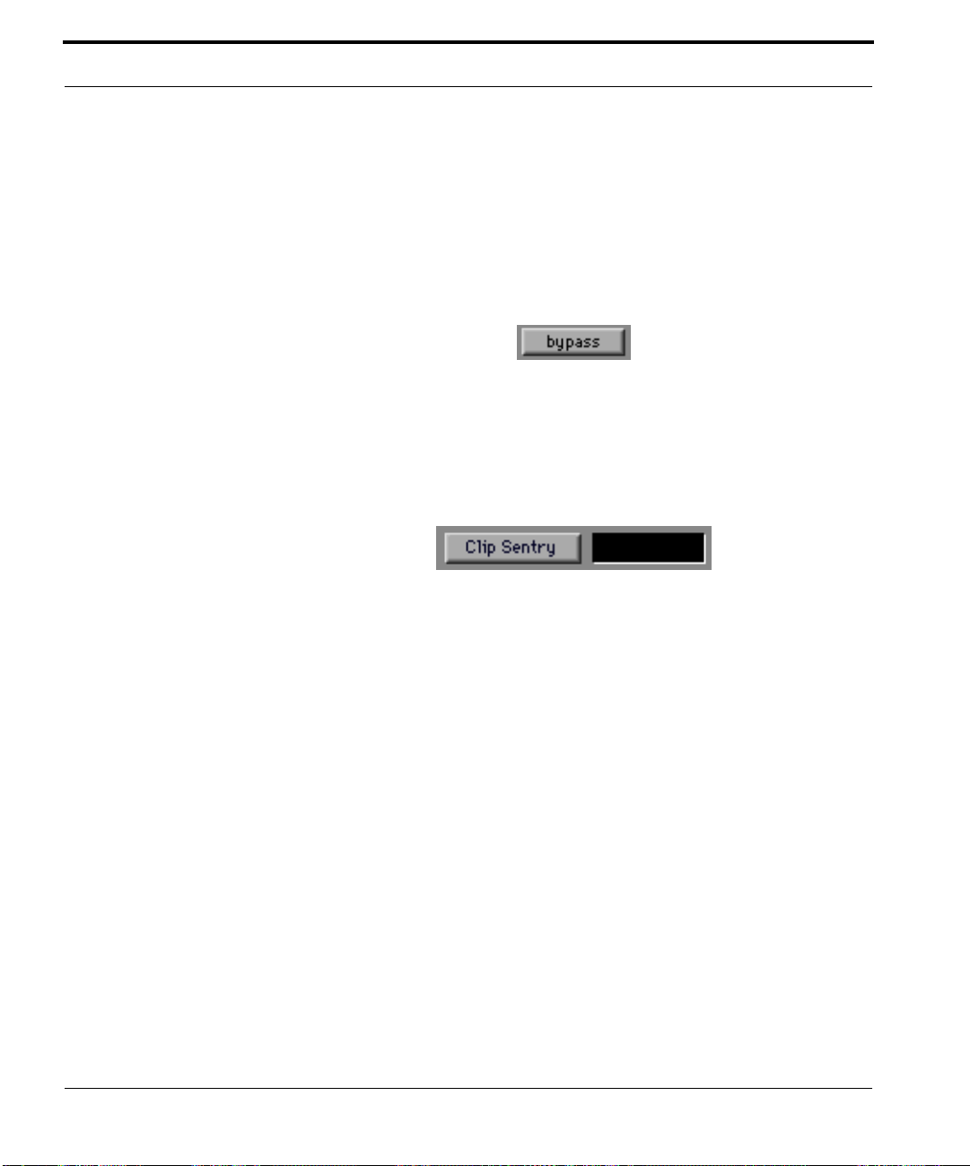
Bypass Button
Clicking on the Bypass button bypasses the settings of MDT. This is useful
for comparing the original soundÞle to the processed version being previewed. Clicking again will revert to the current settings.
Clip Sentry Button
54 MDT UserÕs Manual
Because MDT simulates the smooth sound of analog compressors, it is easy
to create data that exceeds to +1,-1 digital range. This is because of the
behavior of the Attack Time slider, which allows you to control the rate of
gain reduction due to a sudden increase in sound level. As in the analog
world, even a fast attack time will let through a faster transient. Since most
users jack-up the output gain to compensate for compression, these fast
transients almost always result in clipped data.
Clip Sentry is a high speed digital limiter designed to prevent clipping by a
reducing gain only when clipping is about it occur.
The indicator light to the right of the Clip Sentry button shows when the
Clip Sentry is being activated.

Clip Sentry Buf Len (mS) slider
A very short length will introduce distortion by making rapid gain reductions. This distortion will be minimal if Clip Sentry does not reduce the gain
too often or too much. A long length will introduce more delay in the processed data and even produce audible drop-outs before transients on some
sounds.
Clip Sentry Release (mS) slider
If a large gain reduction occurs, a very short release will be less audible, but
may sound unnatural. A short release also increases the chance that the gain
will recover too quickly, causing a mild clipping of audio data that is
already in the buffer. A release time of 100 rarely produces clipping. A
longer release time will be more audible. The Release (mS) slider controls
how rapidly the gain is allowed to change. Hence, you have the Release
Slider set to 1000 and rapidly increase the Gain Slider, you will Þnd the
actual output gain shows by the gain reduction meter will increase slowly.
Clipping Indicator
With MDÕs soft clipping, it is difÞcult to hear when clipping occurs. To Þx
this, use the Clip Indicator above the Gain Reduction meter. The Clip Indicator is initially black. It brießy turns yellow whenever MDT output hits
MDT UserÕs Manual 55

MDT Reference
+1,-1 values. After the yellow subsides, it latches to red. You may reset it to
black by clicking on it.
Control Surface Support
TDM pagetables have been implemented allowing MDT to be controlled by
external control surfaces, including the JL Cooper CS-10, Peavey PC 1600,
Digidesign ProControl and Mackie HUI.
Delay Window
The Delay Window shows the amount of time in seconds that MDT will
delay a trackÕs sound output. This delay is introduced due to MDTÕs Òlook
aheadÓ peak detection feature and processing delay. The amount of the
delay introduced gets larger with the number of bands used. Tracks can be
slipped to the left by the amount shown in the Delay Window to resynchronize their output with other non-processed tracks.
56 MDT UserÕs Manual
Filter Mode Menu
MDT uses digital Þlters to separate the energy of the input signal into multiple bands. The Filter Mode Menu contains the following choices:
¥ Full Band: No Þlters are used. The sound is processed in one band. The
frequency response of this mode is 0 Hz to the Nyquist, ±0.0 dB with no
passband ripple.
¥ 3 Band: The signal is divided into 3 equal bands, 3 octaves in width. The
frequency response of this mode is 0 Hz to the Nyquist, ±0.0 dB with
±0.7 dB passband ripple.

¥ 5 Band: The signal is divided into 5 equal bands, 2 octaves in width. The
frequency response of this mode is 0 Hz to the Nyquist, ±0.0 dB with
±0.3 dB passband ripple.
¥ 3 Band AP: The signal is divided into 3 equal bands with a special Þlter
design optimized for the ßattest pass band near unity gain. The fre-
quency response of this mode is 0 Hz to the Nyquist, ±0.0 dB with ±0.0 to
0.7 dB passband ripple.
¥ 5 Band AP: The signal is divided into 5 equal bands with a special Þlter
design optimized for the ßattest pass band near unity gain. The fre-
quency response of this mode is 0 Hz to the Nyquist, ±0.0 dB with ±0.0 to
0.3 dB passband ripple.
The AP (all pass) versions of the multiband Þlters are optimized for minimum coloration at gains around 0 dB. Because of hardware limitations, the
AP mode Þlters have a limited gain reduction range of -12 dB. This means
that the input signal can't be attenuated more than 12 dB without having its
tonal balance seriously altered. In cases where more gain reduction is
needed, the normal non-AP version of the Þlter will give the best result.
Placing the I/O Curve in
the shaded parts of the Grid will
cause unpredictable
changes in the tonal
balance when using AP
mode filters.
MDT UserÕs Manual 57

MDT Reference
Flat Button
Pressing the Flat Button equalizes the apparent input level of the bands displayed in multiband modes. MDT adjusts the offset of each band to equal
the apparent level of the quietest band. As long as you hold down the ÒFlatÓ
button, the spectral band levels are averaged, and input offset level adjustments are continuously updated. Consequently, the average coloration over
the period the ÒFlatÓ button is held down will be neutral.
Gain Slider
The Gain slider adjusts the loudness of the signal after processing. The
range of the control is from -24 dB to +24 dB. The current gain is displayed
in the window to the left of the slider.
58 MDT UserÕs Manual
Clicking on the arrows decrements/increments the gain by one deciBel.
Pressing on the arrows decrements/increments the gain continuously. Press
<option> to slow the speed at which the value increments. The thumb
wheel can be dragged for making gross adjustments.
Input Offset Arrows
The Input Offset Arrows allow you to change the relationship of the input
signal to the I/O Curve without actually changing the signal level of the
input data. The placement of thresholds can be tweaked in this way. In
multiband conÞgurations, spectral bands can be independently adjusted.
By adjusting the different bands to the same input level, coloration is
reduced. Adjusting the different bands to completely separate sections of
the I/O Curve allows independent compression ratios and levels for each
band. The range of adjustment is from 0 dB to -96 dB.
The Input Offset Arrows normally increment in 2 dB steps. Press <option>
then click or press on the arrows to increment is 1 dB steps.

Input Offset Arrows
Input Offset Display
In/Out Display
The In/Out Display shows the position of the cursor when it is located
inside the In/Out Grid. The units displayed are in dB below full scale. The
In/Out Display shows the location of thresholds and terminators when
they are being dragged.
When dragging a threshold, the In/Out Display also shows the compression or expansion ratios of the curve segments on either side of the threshold. Ratios expressed as N to 1 are compression ratios. Ratios expressed as 1
to N are expansion ratios. Ratios expressed as 1 to -N or -N to 1 are inverse
gain curves which donÕt have equivalents in the analog world.
In/Out Grid
The In/Out Grid is the primary interface for controlling MDT.
MDT UserÕs Manual 59

MDT Reference
-72:-48
All the possible points where the I/O Curve can exist are represented by the
In/Out Grid. It is divided by a diagonal line that represents the points on
the Grid that have input levels equal to output levels (e.g. -48:-48). Placing
the I/O Curve on this diagonal will cause MDT to output the signal at the
same level as it was input.
The points on the Grid which have output levels lower than their input levels (e.g. -48:-72) are located below the diagonal. Placing the I/O Curve
below the diagonal will cause MDT to output the signal at a lower level
than it was input.
Points on the Grid which have output levels higher than their input levels
(e.g. -72:-48) are located above the diagonal. Placing the I/O Curve above
the diagonal will cause MDT to output the signal at a higher level than it
was input.
Click, or click-drag to position new points on the I/O Grid. To delete a
point, place the cursor over the point (a special cursor is activated) and
option-click the point.
-48:-48
-48:-72
60 MDT UserÕs Manual
To move a point, place the cursor over the point (a special cursor is activated) and click-drag it. The new setting takes effect while the mouse is
moving (you hear the drag as you move the point). On slower machines,
you may want to press and hold down <shift> while changing the I/O
Curve. This will cause MDT change the curve setting only after the point
drag is complete.

Release Slider
The Release slider adjusts the time it takes for MDT to return to its quiescent state after a peak comes through. The range of the control is from 0 milliseconds to 5,000 milliseconds. The current release time is displayed in the
window to the left of the slider.
Clicking on the arrows changes the release time in small increments. Pressing on the arrows decrements/increments the release time continuously.
Pressing <option> before clicking or pressing on the arrows decrements/
increments the release time in 1 millisecond steps. The thumb wheel can be
dragged for making gross adjustments.
Reset Button
Clicking the Reset Button zeros the Input Offset values shown in the Input
Offset Window.
Setting Menu
The Setting menu contains the list of settings that are stored in the MDT
Preferences Þle in the System Extensions folder. Any number of settings can
be saved in the Setting menu.
To save a setting;
1. Choose Save Settings AsÉ from the Settings menu.
A dialog box appears requesting a setting name.
2. Type the desired name in the text box and click on Save.
MDT UserÕs Manual 61

MDT Reference
The settings are now saved. These settings appear at the bottom of the
Setting menu.
To recall a setting;
1. Choose it from the Setting menu.
The settings are recalled as you saved them.
To delete the setting;
1. Choose Delete SettingsÉ from the Setting menu.
A dialog appears with the list of the settings in the menu.
2. Scroll down to Test and select it by clicking on it.
3. Click on the Delete button.
The setting is deleted from the menu. You may select multiple settings
for deletion by shift-clicking or click dragging over the items to be
deleted. To make a non-contiguous selection, press <command> and
click on the items to select them. Note that the settings themselves
remain on MDT until they are moved or another setting is chosen.
62 MDT UserÕs Manual
TDM Settings and the Compare Button
The ProTools 4 TDM settings feature has been implemented. The TDM settings recall all control values (all buttons and sliders) as well as the I/O
curve. Although recalling these settings is not automated as the MDT Settings menu has been, the TDM settings features do offer additional ßexibility in selecting Þle storage options.
The ProTools 4 ÒCompareÓ button has been implemented. This provides
automatic comparison between the current TDM setting and the existing
control values (including the I/O curve points). By pressing the ÒCompareÓ
button, you can instantly exchange these settings, effectively doing an A/B
comparison.
When the ProTools 4 TDM settings feature or the ÒCompareÓ button are
used, the MDT Settings menu is restored to the saved status. However, the
remaining control settings reßect other restored values rather than values
from the MDT Setting menu item

Thresholds And Terminators
THRESHOLD
Upper T erminator
Lower Terminator
Up to 30 thresholds can be placed on the In/Out Grid to Òrubber bandÓ the
I/O Curve. The rules for using thresholds are as follows.
To: Do This:
place a threshold on the curve, click in the In/Out Grid.
display the location of a threshold click on the threshold
move an existing threshold, click and drag it to the new location.
delete a threshold, press <option> and click on the threshold.
The lower terminator is ÒgluedÓ to the In axis. It will always have an Out
value of -96 dB. It can never exist to the right of a threshold, that is, have a
higher input value than a threshold. This is to prevent the I/O Curve from
having more than one output value for any given input value.
The upper terminator is glued to the Out axis. It will always have an In
value of 0dB.
Variable Button
MDT is unbelievably smooth because it removes pumping by compressing
spectral bands separately. However, the most problematic aspect of MDT
(and all multiband compressors) is created by the multiband feature: When
some spectral bands are hotter than others, they are compressed more,
thereby coloring the sound.
MDT UserÕs Manual 63

MDT Reference
IMPORTANT:
Setting this button causes the input offset levels to be continuously adjusted
so the band levels are, on the average, even with one-another. This causes
the output sound to have no coloration. The speed of these adjustments is
three times slower than the compressor release time. Hence, no matter what
the release time setting is, using the ÒVariableÓ button will not interfere
with the bands compressing independently from one-another. Once the
ÒVariableÓ button is set, pressing any other level control (ÒFlatÓ, ÒResetÓ or
the input offset arrows) pops it out.
The ÒVariableÓ button requires CPU processing to work. MDT does this processing when it is given control of the CPU to update meters. MDT is not
given the CPU when the plugin is not visible. Hence, the ÒVariableÓ button
will not work when the plugin is not visible. In order to achieve the effect of
the ÒVariableÓ button when the plugin is not visible, you must record the
resulting input offset level changes using automation in ProTools 4.
64 MDT UserÕs Manual

CHAPTER 5 Theory of Operation
MDT has been designed to provide enormous power and ßexibility through
the use of a simple user interface. However, since MDT is a new technology,
some users may Þnd it interesting or helpful to have a deeper
understanding of the conceptual elements of MDT's actual processing
algorithms.
This chapter has been written to satisfy that need. The concepts behind
MDT's processing algorithms are presented here in sufÞcient detail so that
the behavior of MDT is precisely explained. To provide as much simplicity
as possible, the various sections of this chapter describe the processing that
occurs for monaural sound data. The last section of the chapter describes
how MDT processing occurs for a stereo sound source.
The Gain Adjust Algorithm
The most basic computation in MDT is the Gain Adjust. In the various
diagrams in this chapter, the Gain Adjust computation is represented by the
symbol:
Gain Adjust
The purpose of the Gain Adjust computation is to perform the gain
computation on one channel of data. This includes computing the signal
level, scaling the level according to the user deÞned input level offset value,
MDT UserÕs Manual 65

The Gain Adjust Algorithm
and computing and applying the Þnal gain. The details of the Gain Adjust
computation are given by the diagram:
input level offset
input
compute
level
delay
input
level
multiply
scaled
input
level
output
level
output level
÷ input level
output
gain
output
multiply
The diagram above shows that as each sound sample is presented, a new
input level is computed. The input level is a positive valued number
between 0 (-96 dB) and 1 (0 dB). The input level is then multiplied by the
user deÞned input level offset value to give the scaled input level. This
value is presented to the user on the In/Out Grid as a horizontal bar. It is
then used as the input setting on the I/O Curve to look-up the output level.
The output level is divided by the input level to produce the output gain.
As an example of this processing, consider the case where the I/O Curve is
a 45 degree 1:1 diagonal. In this case, the output level will always equal the
scaled input level and the resulting output gain will always be unity. This
means the sample output will be identically equal to the sample input.
Each incoming sound sample is also stored in a Þrst in/Þrst out (FIFO)
buffer. To compute the output sound, samples are taken from the FIFO
buffer. This is represented in the diagram above as delay. The amount of
delay introduced by MDT is shown in the Delay Window.
For example, suppose the I/O Curve represents a compressor plus gain.
Soft sound data would result in a high output gain. With no delay, if the
sound were to become loud more quickly than the attack time, the high
output gain would be applied to the loud sound resulting in output
overßow and clipping. With a delay present, the output gain would be
reduced before the delayed sound arrives, and a reduced output gain
would be applied to the data, preventing overßow and clipping.
It is important to distinguish the use of the input level offset. This value
only changes the displayed level, the corresponding output level look-up
from the I/O Curve, and the gain computation. In this way, the input level
offset serves only to change the position on the I/O Curve from which the
gain is computed.
MDT UserÕs Manual 66

The Gain Adjust Algorithm
In the Gain Adjust computation, the compute level box depicts the
computation of the input level from the sound samples. The compute level
computation is depicted in the ßowchart:
input
absolute
value
abs
level > abs
yes
decay <– attack decay
?
no
decay <– release decay
level <– decay • level + (1 - decay) • abs
new level
This ßowchart shows that the absolute value of each sound sample is Þrst
compared with the previously computed level. If the absolute value is
greater than the previously computed level, then a decay value
corresponding to the attack time is used, otherwise a decay value
corresponding to the release time is used. (The decay values are positive
and slightly less than one, which result the proper decay or release times.)
The decay value is then used to update the level value using the equation
shown in the ßowchart. When the attack time is shorter that the release
time, the resulting level approximates the largest instantaneous amplitudes
in the data. Other settings result in levels that are less than the largest
instantaneous amplitudes in the data.
MDT UserÕs Manual 67

The ÒFull BandÓ Filter Mode
The “Full Band” Filter Mode
This is the simplest computation. In this Þlter mode, the sound data is input
to the Gain Adjust. The output of the Gain Adjust is multiplied by the Gain
slider value for the Þnal output:
Gain slider value
input
Gain Adjust
multiply
output
The “Standard” Filter Modes
The following diagram depicts the Ò3 bandÓ and Ò5 BandÓ Þlter modes:
input
Filter 1
Filter 2
Filter n
Parametric
Equalizer Filters
The input signal is Þrst split into separate bands using parametric equalizer
Þlters. Each of these Þltered signals is processed by a separate Gain Adjust
algorithm. Hence each band embodies separate input level computations
and well as separate gain computations. The delays in each of the Gain
Adjust computations are the same. Hence no phase effects are present from
differing delays. After the Gain Adjust computation, the separate bands are
summed together and multiplied by the Gain slider value to give the
output.
Gain Adjust
Gain Adjust
Gain Adjust
sum
Gain slider value
output
multiply
MDT UserÕs Manual 68
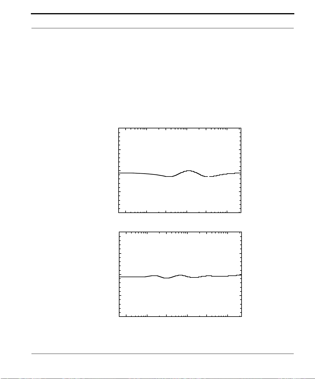
The ÒStandardÓ Filter Modes
The center frequencies of the parametric equalizer Þlter pass bands are 140,
1120, and 8960 Hz (3 octave spacing) for the 3 Band Þlters and 40, 160, 640,
2560, and 10240 Hz (2 octave spacing) for the 5 Band Þlters.
Consider the case where the I/O Curve is a 45 degree 1:1 diagonal. In this
case, all output levels will equal the scaled input levels and the resulting
output gains will be unity. This means the Gain Adjust output will equal the
Gain Adjust inputs. The resulting overall output will then have the transfer
function characteristic of the parametric equalizer. The graphs below show
the frequency response of the multiband Þlters with unity output gain.
10
5
))
))
BB
BB
dd
dd
((
((
ee
ee
dd
dd
uu
uu
tt
tt
ii
ii
0
nn
nn
gg
gg
aa
aa
MM
MM
gg
gg
oo
oo
LL
LL
-5
-10
10
5
))
))
BB
BB
dd
dd
((
((
ee
ee
dd
dd
uu
uu
tt
tt
ii
ii
0
nn
nn
gg
gg
aa
aa
MM
MM
gg
gg
oo
oo
LL
LL
-5
100 300 1000 3000 1000020 22050
MDT 2.0 3 band transfer characteristic
yy
FFFFrrrreeeeqqqquuuueeeennnnccccyy
MDT 2.0 5 band transfer characteristic
-10
100 300 1000 3000 1000020 22050
FFFFrrrreeeeqqqquuuueeeennnnccccyy
yy
MDT UserÕs Manual 69

The ÒAPÓ Filter Modes
The “AP” Filter Modes
In some cases, the ±0.3 dB of passband ripple in the parametric equalizer
Þlters of the standard Þlter modes are not desirable. The AP Þlter modes do
not have these artifacts provided certain limitations can be met. The
following diagram depicts the Ò3 band APÓ and Ò5 Band APÓ Þlter modes:
input
Filter 1
Filter 2
Filter n
Parametric
Equalizer Filters
Gain Adjust
Gain Adjust
Gain Adjust
sum
Gain slider value
multiply
output
-1
-1
-1
This diagram is the same as the standard Þlter mode diagram except for the
additional data paths show as heavier lines. Consider the following subdiagram:
Gain Adjust
-1
The triangle near the -1 shows the signal is multiplied by -1. In the case
where the I/O Curve is a 45 degree 1:1 diagonal, the output of the Gain
Adjust is identically equal to the input. Therefore the output of the subdiagram is zero. Referring now back to the larger diagram, the only input to
the ÒsumÓ is directly from the overall input, in which case, the output of the
AP Þlter mode is simply the Gain slider applied to the input with no
parametric equalizer Þlters artifacts.
When the I/O Curve deviates from a 45 degree 1:1 diagonal, output occurs
from the sub-diagram, and the characteristics of the re-combined signal
depend on the phase characteristics of the parametric equalizer Þlters.
SpeciÞcally, these Þlters are designed so that there is a zero degree phase
shift in the center of each pass band. Consequently, a gain increase
indicated by the I/O Curve results in a gain increase in the overall output
MDT UserÕs Manual 70

Clip Sentry
and a gain decrease indicated by the I/O Curve results in a gain decrease in
the overall output.
In this way, the AP Þlter modes are able to accomplish compression and
expansion computations without artifacts from the parametric equalizer
Þlters.
However, these effects are limited to the I/O Curve operating within plus
and minus 12 dB of the 45 degree 1:1 diagonal. Operating above +12 dB of
the diagonal causes the parametric equalizer artifacts to again dominate the
output as they would in the non-AP case. This is not a serious problem.
Operating below -12 dB is more of a problem: Because there is a zero degree
phase shift in the center of each pass band, these frequencies will be
handled properly. However, the phase changes in the crossover and stop
band of each Þlter will cause the sound at these frequencies to not be
correctly subtracted, leaving a signiÞcantly audible sound in the output.
Clip Sentry
Because MDT simulates the smooth sound of analog compressors, it is easy
to create data that exceeds to +1,-1 digital range. This is because of the
behavior of the Attack Time slider, which allows you to control the rate of
gain reduction due to a sudden increase in sound level. As in the analog
world, even a fast attack time will let through a faster transient. Since most
users jack-up the output gain to compensate for compression, these fast
transients almost always result in clipped data.
Clip Sentry is a high speed digital limiter designed to prevent clipping by a
reducing gain only when clipping is about it occur.
When Clip Sentry is activated by pressing the Clip Sentry button, the audio
data is routed through a new buffer, creating delayed output data. Before
each sample is put into the buffer, it is multiplied by the current gain. If an
clipping occurs, then the current gain is gradually reduced so that when the
culprit audio data appears at the output end of the buffer, the new current
gain does not create clipping. The current gain is then gradually restored
using a release time algorithm.
MDT UserÕs Manual 71

Stereo Sound Processing
The current gain is a combination of gain from the gain curve and the gain
slider. The Clip Sentry processing occurs in the sequence described in the
diagram:
Gain Curve gain
increase and
Gain Slider.
Compressor process with
Gain reduction, only,
from Gain Curve.
CLIP
SENTRY
From this diagram, you see that the Gain Curve is broken up into two parts.
The Þrst part is a new curve that has gain reduction only. This reduction is
compensated for by the second part, a gain increase after Clip Sentry.
Hence, the data coming into Clip Sentry is never clipped. The only existing
limitation of MDT 4.00 is that the maximum curve gain plus the Gain Slider
cannot exceed +48dB.
Clip Sentry can attenuate the gain by as much as -30dB to stop clipping.
Stereo Sound Processing
The left and right channels of stereo signals are processed completely
separately except for a single exception: they both share the same levels.
The signal level computation is described in the Þrst section of this chapter
using the compute level ßowchart. In the case of stereo data, the data
presented to the compute level algorithm alternates between the left and
right channels: L, R, L, R, L, ...
As a result of this arrangement, the same gain will be applied to both
channels of the stereo data at any instant in time.
Another result is that incorrect compression/expansion results will occur if
the two channels contain differing material, or if the channels are not scaled
relative to one-another. In these cases, the louder channel (over the period
of the time scales involved) will dominate the computation.
MDT UserÕs Manual 72

Symbols
“Soft Knee” Compressor 17
“soft knee” compressor 36
“Tube” Compander 18, 36
“tube” companders 37
Numerics
3 Band 56
3 band 68
3 Band AP 57
3 band AP 70
5 Band 57, 68
5 Band AP 57, 70
A
AP Filter Modes 70
AP mode 40
Attack Slider 53
Attack Time 31
attack time 19
auto read 50
auto touch 50
Automation 49, 53
B
Bypass Button 54
C
Clip 48
clip light 48
Clip Sentry 48, 71
Clip Sentry Buf Len 48
Clip Sentry Buf Len (mS) slider 55
Clip Sentry Button 54
Clip Sentry Release 48
Clip Sentry Release (mS) slider 55
Clipping Indicator 55
Compare Button 62
Compression 13
compression ratio 14, 30
Compressor 30
Compressor with Noise Gate 35
Control Surface Support 56
D
De-esser 45
delay 48
Delay Window 56
Delete Settings… 29
MDT UserÕs Manual lxxiii

digital filters 40
DSP Plug-ins 22
Dynamic EQ 47
dynamic range 13, 30
E
effect of changing attack time 19
effect of changing release time 19
Expander/Gate 34
expansion 18
F
Filter Mode Menu 56
Filter Modes 40, 68
filter pass band center frequencies 69
Flat 43
Flat Button 58
Flat button 49
Full Band 56
Full Band Filter Mode 68
G
Gain Adjust Algorithm 65
gain reduction 14, 30
Gain Slider 58
Gain slider 31
H
high speed digital limiter 48
lxxiv MDT UserÕs Manual
I
I/O Curve 23, 25, 66
I/O Curve position and gain 26
In/Out Grid 15, 16, 25
input level offset 66
Input Level Offset Arrows 27
Input Offset 43, 44
Input Offset Adjust Arrows 58
Input Offset Arrow 50
Input Offset Display 28
Input Offset Levels 49
Installing The JVP 11
inverse gain functions 24
Inverted Gain Curves 51
L
Levelx 50
look-ahead peak averaging 22
lower terminator 24, 35

M
MDT As A Compressor 15
MDT Basics 21
mixing 13
Multiband Applications 39
multiband center frequencies 69
Multiband Compressor 40
multiband mode 39
Multiband Peak Level Indicators 39
O
Owner Registration 11
P
Peak Level Indicator 22, 28
processing algorithms 65
pumping 19
R
Ratio 14
Release Time 31
release time 19, 22
Reset 43
Reset Button 61
Reset button 49
Reset Settings 29
S
Save Settings As… 29
Setting Menu 28
Settings menu 49
Single Band Applications 30
Spectral Enhancer 45, 46
Stereo Sound Processing 72
T
TDM Settings 62
Technical Support 11
Theory of Operation 65
Threshold 14
threshold 24
Tonal Balance 43
Tonal Balance In Multiband Mode 42
transfer characteristic 23
Tutorial 21
U
upper terminator 24
MDT UserÕs Manual lxxv

V
Variable 43, 44
Variable Button 63
Variable button 49
lxxvi MDT UserÕs Manual
 Loading...