

Page 1

LightningÔ
37xxxE
Vector Network Analyzer
Operation Manual
490 JARVIS DRIVE · MORGAN HILL, CA 95037-2809
P/N: 10410-00300
REVISION: A
PRINTED: AUGUST 2010
COPYRIGHT 2010 ANRITSU CO.
Page 2

WARRANTY
The ANRITSU product(s) listed on the title page is (are) warranted against defects in materials and
workmanship for three years from the date of shipment.
ANRITSU’s obligation covers repairing or replacing products which prove to be defective during the
warranty period. Buyers shall prepay transportation charges for equipment returned to ANRITSU for
warranty repairs. Obligation is limited to the original purchaser. ANRITSU is not liable for consequential
damages.
LIMITATION OF WARRANTY
The foregoing warranty does not apply to ANRITSU connectors that have failed due to normal wear. Also,
the warranty does not apply to defects resulting from improper or inadequate maintenance by the Buyer,
unauthorized modification or misuse, or operation outside of the environmental specifications of the
product. No other warranty is expressed or implied, and the remedies provided herein are the Buyer’s sole
and exclusive remedies.
TRADEMARK ACKNOWLEDGEMENTS
V Connector and K Connector are registered trademarks of ANRITSU Company.
GPC-7 is a registered trademark of Amphenol Corporation.
ANACAT is a registered trademark of EEsof, Inc.
QuietJet and ThinkJet are registered trademarks of Hewlett-Packard Co.
Microsoft, Excel, and MS-DOS are registered trademarks of Microsoft Corporation.
Acrobat and Acrobat Reader are trademarks of Adobe Corporation.
Iomega and Zip are registered trademarks of Iomega Company.
NOTICE
ANRITSU Company has prepared this manual for use by ANRITSU Company personnel and customers as
a guide for the proper installation, operation and maintenance of ANRITSU Company equipment and
computer programs. The drawings, specifications, and information contained herein are the property of
ANRITSU Company, and any unauthorized use or disclosure of these drawings, specifications, and
information is prohibited; they shall not be reproduced, copied, or used in whole or in part as the basis for
manufacture or sale of the equipment or software programs without the prior written consent of ANRITSU
Company.
UPDATES
Updates to this manual, if any, may be downloaded from the Anritsu Internet site at:
http://www.us.anritsu.com.
Page 3
Page 4

Page 5

Safety Symbols
To prevent the risk of personal injury or loss related to equipment malfunction, Anritsu Company uses the
following symbols to indicate safety-related information. For your own safety, please read the information
carefully BEFORE operating the equipment.
Symbols used in manuals
DANGER
WARNING This indicates a hazardous procedure that could result in serious in
This indicates a very dangerous procedure that could result in serious
injury or death if not performed properly.
-
jury or death if not performed properly.
CAUTION This indicates a hazardous procedure or danger that could result in
light-to-severe injury, or loss related to equipment malfunction, if
proper precautions are not taken.
Safety Symbols Used on Equipment and in Manuals
Some or all of the following five symbols may or may not be used on all Anritsu equipment. In addition, there
may be other labels attached to products that are not shown in the diagrams in this manual.
The following safety symbols are used inside or on the equipment near operation locations to provide infor
mation about safety items and operation precautions. Ensure that you clearly understand the meanings of
the symbols and take the necessary precautions BEFORE operating the equipment.
This indicates a prohibited operation. The prohibited operation is indi
cated symbolically in or near the barred circle.
-
-
his indicates a compulsory safety precaution. The required operation is
indicated symbolically in or near the circle.
This indicates warning or caution. The contents are indicated symboli
cally in or near the triangle.
This indicates a note. The contents are described in the box.
These indicate that the marked part should be recycled.
37xxxE OM Safety-1
-
Page 6

For Safety
WARNING
Always refer to the operation manual when working near locations at
which the alert mark, shown on the left, is attached. If the operation,
etc., is performed without heeding the advice in the operation manual,
there is a risk of personal injury. In addition, the equipment perfor
mance may be reduced.
-
Repair
Moreover, this alert mark is sometimes used with other marks and de
scriptions indicating other dangers.
WARNING
When supplying power to this equipment, connect the accessory 3-pin
power cord to a 3-pin grounded power outlet. If a grounded 3-pin outlet
is not available, use a conversion adapter and ground the green wire, or
connect the frame ground on the rear panel of the equipment to ground.
If power is supplied without grounding the equipment, there is a risk of
receiving a severe or fatal electric shock.
WARNING
This equipment can not be repaired by the operator. DO NOT attempt to
remove the equipment covers or to disassemble internal components.
Only qualified service technicians with a knowledge of electrical fire
and shock hazards should service this equipment. There are
high-voltage parts in this equipment presenting a risk of severe injury
or fatal electric shock to untrained personnel. In addition, there is a risk
of damage to precision components.
-
WARNING
Use two or more people to lift and move this equipment, or use an
equipment cart. There is a risk of back injury, if this equipment is lifted
by one person.
Safety-2 37xxxE OM
Page 7

Narrative Table Of Contents
Chapter 1—General Information
This chapter provides a general description of the Anritsu Model 37xxxE Vector Network Analyzer
System and its major units: network analyzer, test set, and frequency source. It also provides
descriptions for the precision component kits, and equipment options. Additionally, it contains the
listing of recommended test equipment.
Chapter 2—Installation
This chapter provides instructions for performing an initial inspection, preparing the equipment for
use, setting up for operation over the IEEE-488.2 (GPIB) Bus, using a printer, and preparing the
units for storage and/or shipment. It also provides a listing of Anritsu Customer Service Centers.
Chapter 3—Network Analyzers, A Primer
This chapter provides an introduction to network analysis and the types of measurements that can
be made using them. It provides general and introductory description.
Chapter 4—Front Panel Operation
This chapter describes the front panel controls and provides flow diagrams for the menus called up
using the front panel controls. It contains the following sub-chapters:
· Front Panel Control-Group Descriptions
· Calibration Keys and Indicators, Detailed Description
· Save/Recall Menu Key and Menus, Key Description and Menu Flow
· Measurement Keys and Menus, Key Descriptions and Menu Flow
·
Channel Keys and Menu, Key Descriptions and Menu Flow
·
Display Keys and Menus, Key Descriptions and Menu Flow
·
Enhancement Keys and Menus, Key Descriptions and Menu Flow
·
Hard Copy Keys and Menus, Key Descriptions and Menu Flow
·
System State Keys and Menus, Key Descriptions and Menu Flow
·
Markers/limits Keys and Menus, Key Descriptions and Menu Flow
·
Disk Storage Interface, Detailed Description
Chapter 5—Error And Status Messages
This chapter describes the type of error messages you may encounter during operation and provides a
tabular listing. This listing describes and defines the error types.
Chapter 6—Data Displays
This chapter provides a detailed description of the various data displays. It describes the graph
types, frequency markers, measurement limit lines, status displays, and data display controls.
37xxxE OM i
Page 8

Narrative Table of Contents (Continued)
Chapter 7—Measurement Calibration
This chapter provides a discussion and tutorial on measurement calibration. It contains step-by-step
calibration procedures for the Standard (OSL), Offset-Short, TRM, and LRL/LRM methods. It also
has a procedure for calibrating using a sliding termination.
Chapter 8—Measurements
This chapter discusses measurements with the 37xxxE VNA. It contains sub-chapters that provide a
detailed descriptions for Transmission and Reflection, Low Level and Gain, Group Delay, Active
Device, Multiple Source Control, Adapter Removal, Gain Compression, and Receiver Mode
measurements
Chapter 9—Time Domain
This chapter describes the Option 2, Time Domain feature. It provides an operational procedure and
a flowchart of the time domain menus.
Chapter 10—AutoCal
This chapter describes the Automatic Calibrator (AutoCal) feature and provides operational information and procedures.
Chapter 11—Operational Checkout Procedures
This chapter provides a procedure for operational checkout
Appendix A—Front Panel Menus, Alphabetical Listing
This appendix shows all of the menus that are called up using the front panel controls. It provides a
replica of the menu and descriptive text for all of the various menu choices. The listing is alphabetical by the menu call letters mentioned and/or illustrated in Chapter 4.
Appendix B—Model 37xxxE VNA Rear Panel Connectors
This appendix describes the rear panel connectors. It also provides pinout listing.
Appendix C—Performance Specifications
For printed versions of this manual, Appendix C contains the Technical Data Sheet, part number
11410-00573, which provides performance specifications.
Index
ii 37xxxE OM
Page 9

Table of Contents
Chapter 1 General Information
1-1 SCOPE OF MANUAL .................................1-3
1-2 INTRODUCTION ...................................1-3
1-3 IDENTIFICATION NUMBER.............................1-3
1-4 ONLINE MANUALS..................................1-3
1-5 SYSTEM DESCRIPTION ...............................1-3
372xxE........................................1-4
373xxE........................................1-4
1-6 OPTIONS........................................1-4
1-7 PRECISION COMPONENT KITS ..........................1-5
Calibration Kits ...................................1-5
Verification Kits ...................................1-5
1-8 PERFORMANCE SPECIFICATIONS ........................1-6
1-9 PREVENTIVE MAINTENANCE ...........................1-6
Chapter 2 Installation
2-1 INTRODUCTION ...................................2-3
2-2 INITIAL INSPECTION ................................2-3
2-3 PREPARATION FOR USE ..............................2-3
Option 4, Additional SD Card for Secure Environments .............2-4
2-4 GPIB SETUP .....................................2-5
Interface Connector .................................2-5
Cable Length Restrictions .............................2-5
2-5 SYSTEM GPIB INTERCONNECTION........................2-6
GPIB Interface to an External Plotter .......................2-6
GPIB Addresses...................................2-6
2-6 ETHERNET SETUP AND INTERCONNECTION..................2-6
2-7 EXTERNAL MONITOR CONNECTOR .......................2-7
2-8 RACK MOUNT.....................................2-7
37xxxE OM iii
Page 10

Table of Contents (Continued)
2-9 STORAGE OR SHIPMENT .............................2-10
Preparation for Storage ..............................2-10
Preparation for Shipment .............................2-10
Chapter 3 Network Analyzers, A Primer
3-1 INTRODUCTION ...................................3-3
3-2 GENERAL DESCRIPTION ..............................3-3
Source Module....................................3-4
Test Set Module ...................................3-4
Analyzer Module ..................................3-4
3-3 NETWORK ANALYZERS ...............................3-5
Chapter 4 Front Panel Operation
4-1 INTRODUCTION ...................................4-3
4-2 KEY-GROUPS .....................................4-3
4-3 CALIBRATION KEY-GROUP ............................4-10
4-4 SAVE/RECALL MENU KEY.............................4-20
4-5 MEASUREMENT KEY-GROUP ..........................4-21
4-6 CHANNELS KEY-GROUP..............................4-24
4-7 DISPLAY KEY-GROUP ...............................4-25
4-8 ENHANCEMENT KEY-GROUP...........................4-29
4-9 HARD COPY KEY-GROUP .............................4-31
4-10 SYSTEM STATE KEY-GROUP ...........................4-33
4-11 MARKERS/LIMITS KEY-GROUP ..........................4-36
4-12 STORAGE INTERFACE ...............................4-40
Disk Files......................................4-40
Disk File Output Device..............................4-41
Formatting a Data File Drive ...........................4-41
Copying Data Files From Drive to Drive .....................4-41
Recovering From Drive Write/Read Errors....................4-41
iv 37xxxE OM
Page 11

Table of Contents (Continued)
4-13 COMMAND LINE ..................................4-41
Create Directory ..................................4-42
List Directory ...................................4-42
Change Directory .................................4-42
Delete Files.....................................4-42
Remove Directory .................................4-43
Copy Files .....................................4-43
Conventions ....................................4-43
Chapter 5 Error and Status Messages
5-1 INTRODUCTION ...................................5-3
5-2 ERROR MESSAGES..................................5-3
Chapter 6 Data Displays
6-1 INTRODUCTION ...................................6-3
6-2 DISPLAY MODES AND TYPES ...........................6-3
Single Channel Display: Ch 1, 2, 3, 4........................6-3
Dual Channel Display: Ch 1 and 3 or Ch 2 and 4 .................6-4
Four Channel Display: Ch 1, 2, 3, 4 ........................6-5
Dual Trace Overlay .................................6-6
Graph Data Types..................................6-7
6-3 FREQUENCY MARKERS ..............................6-11
Marker Designation ................................6-11
6-4 LIMITS ........................................6-11
6-5 STATUS DISPLAY ..................................6-12
Reference Position Marker ............................6-12
Scale Resolution ..................................6-12
Frequency Range .................................6-12
Analog Instrument Status.............................6-12
Measurement Status ...............................6-13
Sweep Indicator Marker..............................6-13
6-6 DATA DISPLAY CONTROL .............................6-13
S-parameter Selection ...............................6-14
Data Display Update ...............................6-14
Display of Markers.................................6-14
37xxxE OM v
Page 12

Table of Contents (Continued)
6-7 HARD COPY AND STORAGE OUTPUT ......................6-15
Tabular Printout ..................................6-15
Screen-Image Printout ..............................6-15
Plotter Output ...................................6-15
Storage Output...................................6-15
Chapter 7 Measurement Calibration
7-1 INTRODUCTION ...................................7-3
7-2 DISCUSSION .....................................7-3
Establishing the Test Ports.............................7-3
Understanding the Calibration System ......................7-5
Calibrating for a Measurement ..........................7-9
Evaluating the Calibration ............................7-11
Verification Kits ..................................7-11
7-3 SLIDING TERMINATION..............................7-13
7-4 SOLT CALIBRATION ................................7-19
7-5 OFFSET-SHORT CALIBRATION (SSLT) ......................7-28
7-6 TRIPLE OFFSET-SHORT CALIBRATION (SSST).................7-32
7-7 LRL/LRM CALIBRATION ..............................7-36
7-8 TRM CALIBRATION.................................7-46
7-9 MERGE CAL FILES APPLICATION ........................7-47
Chapter 8 Measurements
8-1 INTRODUCTION ...................................8-3
8-2 TRANSMISSION AND REFLECTION ........................8-3
8-3 LOW LEVEL AND GAIN ..............................8-12
8-4 GROUP DELAY ...................................8-20
8-5 ACTIVE DEVICE ..................................8-24
8-6 MULTIPLE SOURCE CONTROL ..........................8-29
Control Formula ..................................8-29
8-7 ADAPTER REMOVAL ................................8-34
vi 37xxxE OM
Page 13

Table of Contents (Continued)
8-8 GAIN COMPRESSION................................8-39
Power and VNAs ..................................8-39
Swept Power Gain Compression .........................8-41
Swept Frequency Gain Compression .......................8-41
8-9 RECEIVER MODE ..................................8-58
Source Lock Mode .................................8-58
Tracking Mode ...................................8-58
Set-on Mode ....................................8-58
Receiver Mode Block Diagram ..........................8-59
Receiver Mode Menus ...............................8-59
Procedure, Receiver Mode Operation .......................8-59
8-10 EMBEDDING/ DE-EMBEDDING..........................8-62
Embedding .....................................8-63
De-embedding ...................................8-64
8-11 OPTICAL APPLICATION ..............................8-65
E/O Measurements ................................8-65
O/E Measurements ................................8-68
Creating a Characterization (*.S2P) File for E/O and O/E Measurements . . . 8-74
Chapter 9 Time Domain
9-1 INTRODUCTION ...................................9-3
9-2 TIME DOMAIN MEASUREMENTS .........................9-3
9-3 OPERATING TIME DOMAIN ............................9-8
9-4 WINDOWING.....................................9-11
9-5 GATING........................................9-12
9-6 ANTI-GATING ....................................9-14
9-7 EXAMPLES,GATING AND ANTI-GATING ....................9-14
9-8 TIME DOMAIN MENUS...............................9-14
Chapter 10 AutoCal
10-1 INTRODUCTION...................................10-3
10-2 DESCRIPTION ....................................10-3
10-3 CALIBRATIONS ...................................10-4
10-4 DEFINITIONS ....................................10-4
37xxxE OM vii
Page 14

Table of Contents (Continued)
10-5 PHYSICAL SETUP..................................10-6
10-6 CHARACTERIZATION FILES ...........................10-7
10-7 USING AUTOCAL ..................................10-9
10-8 PIN DEPTH SPECIFICATIONS ..........................10-13
10-9 AUTOCAL MENUS FLOW DIAGRAM ......................10-14
Chapter 11 Operational Checkout Procedures
11-1 INTRODUCTION...................................11-3
11-2 REQUIRED EQUIPMENT..............................11-3
11-3 INITIAL SETUP ...................................11-3
11-4 SELF TEST ......................................11-3
11-5 NON-RATIO POWER ................................11-4
11-6 HIGH LEVEL NOISE TEST.............................11-6
Appendix A Front Panel Menus, Alphabetical Listing
Appendix B Rear Panel Connectors
Appendix C Performance Specifications
Subject Index
viii 37xxxE OM
Page 15

Chapter 1
General Information
Table of Contents
1-1 SCOPE OF MANUAL .................................1-3
1-2 INTRODUCTION ...................................1-3
1-3 IDENTIFICATION NUMBER.............................1-3
1-4 ONLINE MANUALS..................................1-3
1-5 SYSTEM DESCRIPTION ...............................1-3
372xxE........................................1-4
373xxE........................................1-4
1-6 OPTIONS........................................1-4
1-7 PRECISION COMPONENT KITS ..........................1-5
Calibration Kits ...................................1-5
Verification Kits ...................................1-5
1-8 PERFORMANCE SPECIFICATIONS ........................1-6
1-9 PREVENTIVE MAINTENANCE ...........................1-6
Page 16

Figure 1-1. Model 37347E Vector Network Analyzer System
Page 17

GENERAL INFORMATION SCOPE OF MANUAL
Chapter 1 General Information
1-1 SCOPE OF MANUAL This manual provides general information, installation, and operating
information for the Model 37xxxE Vector Network Analyzer (VNA)
system. (Throughout this manual, the terms VNA, 37xxxE VNA, and
37xxxE will be used interchangeably to refer to the system.)
1-2 INTRODUCTION This section provides general information about the 37xxxE VNA
system and one or more precision-component calibration or
performance verification kits. The section also provides a listing of
recommended test equipment.
1-3 IDENTIFICATION
NUMBER
All Anritsu instruments are assigned a unique six- or seven-digit ID
number, such as “940101.”This number is affixed to a decal on the
rear panel of each unit. In any correspondence with Anritsu Customer
Service, please use this number.
1-4 ONLINE MANUALS Manual updates, if any, are available on Anritsu's Internet download
page (http://www.us.anritsu.com/downloads/).
1-5 SYSTEM DESCRIPTION The 37xxxE Network Analyzer (Figure 1-1) is a single-instrument sys
tem that contains a built-in source, test set, and analyzer. It is pro
duced in two series— 372xxE and 373xxE—described below. All mod
els provide up to 1601 measurement data points, a built-in SD Card
for storing and recalling front panel setups and measurement and cali
bration data. They also provide an on-screen display of total opera
tional time and dates of system calibrations. They support operation
over the IEEE 488.2 General Purpose Interface Bus (GPIB).
-
-
-
-
-
1-3 37xxxE OM
Page 18

OPTIONS GENERAL INFORMATION
372xxE The 372xxE is a fully functioning VNA for making passive-device mea-
surements. The series offers three models that cover a range from
40 MHz to 65 GHz. The models are shown below:
Model Frequency Range
37247E 40.0 MHz to 20.0 GHz
37269E 40.0 MHz to 40.0 GHz
37297E 40.0 MHz to 65.0 GHz
373xxE The 373xxE is a fully functioning VNA for making passive- and ac-
tive-device measurements. The series offers three models that cover a
range from 40 MHz to 65 GHz. The models are shown below.
Model Frequency Range
37347E 40.0 MHz to 20.0 GHz
37369E 40.0 MHz to 40.0 GHz
37397E 40.0 MHz to 65.0 GHz
1-6 OPTIONS The following instrument options are available:
q Option 1: Rack Mount Kit
q Option 2: Time (Distance) Domain Measurement Capability
q Option 4: Additional Secure Digital Memory Card (SD Card)
q Option 15: Flexible test set (provides access to all four samplers
and Source loops for each port)
1-4 37xxxE OM
Page 19
GENERAL INFORMATION PRECISION COMPONENT KITS
1-7 PRECISION COMPONENT
KITS
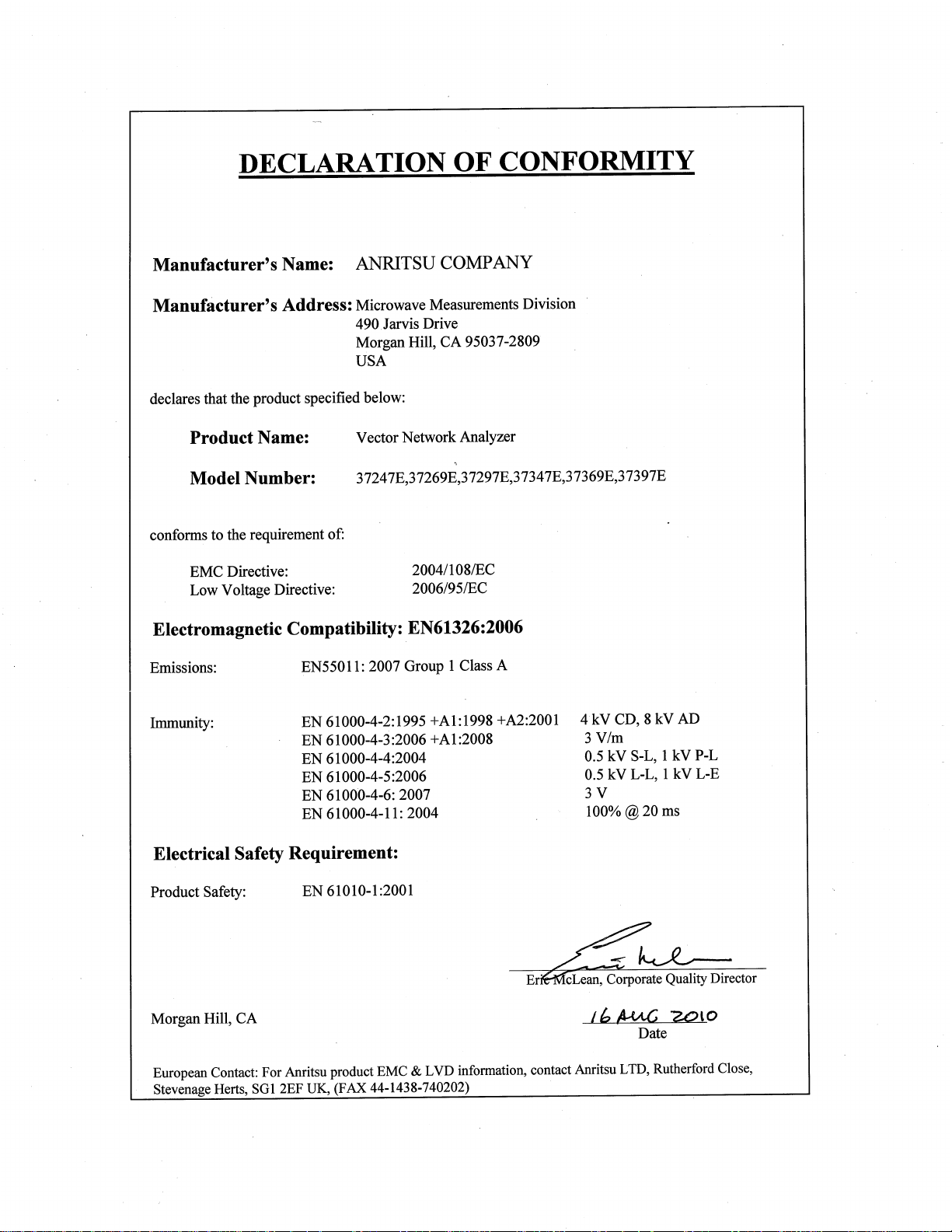
Calibration Kits Calibration kits contain components used to identify and separate er
Figure 1-2. Typical Model 365X
Calibration Kit
Two types of precision-component kits are available: calibration and
verification.
ror sources inherent in microwave test setups. The Model 365X Cali
bration Kits contain all of the precision components and tools required
to calibrate the VNA for 12-term error-corrected measurements of test
devices with the connector type specified. When applicable, compo
nents are included for calibrating both male and female test ports. The
kits also support calibrations with broadband loads.
Each of the available calibration kits are described in detail in the Vec
tor Network Analyzer Mechanical Calibration Kits Reference Manual,
PN: 10410-00278. A typical Model 365X Calibration Kit is shown in
Figure 1-2. The following is a list of available 365X Calibration Kits:
q Model 3650A SMA/3.5 mm Calibration Kit
q Model 3651A GPC–7 Calibration Kit
q Model 3652A K Connector Calibration Kit
q Model 3653A Type N Calibration Kit
q Model 3654D V Connector® Calibration Kit
-
-
-
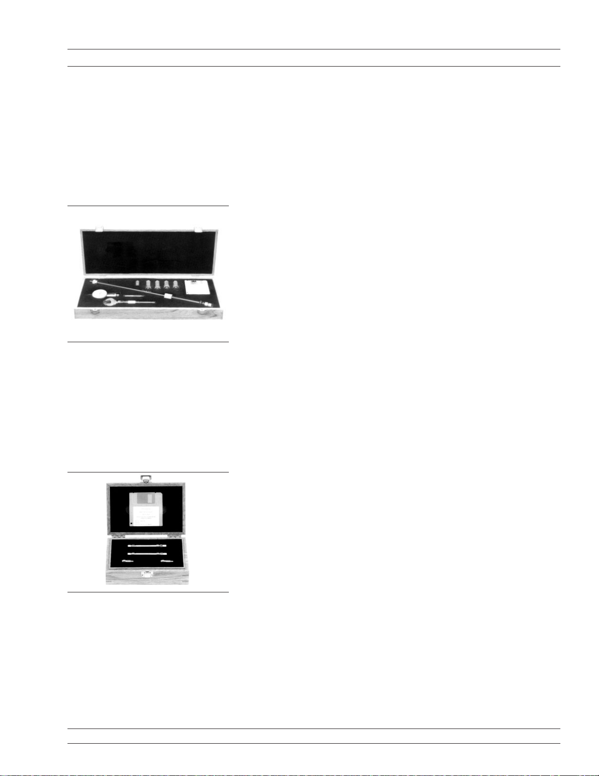
Verification Kits The Model 366X Verification kits consist of precision components of
the connector type specified with characteristics traceable to the
National Institute of Standards and Technology (NIST). This type of
kit is usually kept in the metrology laboratory where it provides the
most dependable means of checking system accuracy. Each of these
-
-
Figure 1-3. Typical Model 366X
VerificationKit
kits contains a disk or USB drive providing factory-measured coeffi
cient or test data for each component, allowing for comparison with
customer-measured data.
A typical Model 365X Verification Kit is shown in Figure 1-3. The fol
lowing is a list of available 366X Verification Kits:
q
Model 3666 3.5 mm Verification Kit
q
Model 3667 GPC–7 Verification Kit
q
Model 3668 K Connector® Verification Kit
q
Model 3669/3669B V Connector® Verification Kits
37xxxE OM 1-5
Page 20

PERFORMANCE SPECIFICATIONS GENERAL INFORMATION
1-8 PERFORMANCE
SPECIFICATIONS
1-9 PREVENTIVE
MAINTENANCE
System performance specifications are provided in Appendix C.
The 37xxxE VNA system does not require any preventive
maintenance.
1-6 37xxxE OM
Page 21

Chapter 2
Installation
Table of Contents
2-1 INTRODUCTION ...................................2-3
2-2 INITIAL INSPECTION ................................2-3
2-3 PREPARATION FOR USE ..............................2-3
Option 4, External SCSI Drive Setup .......................2-4
2-4 GPIB SETUP .....................................2-5
Interface Connector .................................2-5
Cable Length Restrictions .............................2-5
2-5 SYSTEM GPIB INTERCONNECTION........................2-6
GPIB Interface to an External Plotter .......................2-6
GPIB Addresses...................................2-6
2-6 ETHERNET SETUP AND INTERCONNECTION..................2-6
2-7 EXTERNAL MONITOR CONNECTOR .......................2-7
2-8 RACK MOUNT.....................................2-7
2-9 STORAGE OR SHIPMENT .............................2-10
Preparation for Storage ..............................2-10
Preparation for Shipment .............................2-10
2-10 SERVICE CENTERS.................................2-11
Page 22

Page 23

Chapter 2 Installation
2-1 INTRODUCTION This chapter provides information for the initial inspection and
preparation for use of the 37xxxE Vector Network Analyzer.
Information for interfacing the 37xxxE to the IEEE-488 General
Purpose Interface Bus and reshipment and storage information is also
included.
2-2 INITIAL INSPECTION Inspect the shipping container for damage. If the container or cushion
ing material is damaged, retain until the contents of the shipment
have been checked against the packing list and the instrument has
been checked for mechanical and electrical operation.
If the 37xxxE is damaged mechanically, notify your local sales
representative or Anritsu Customer Service. If either the shipping
container is damaged or the cushioning material shows signs of stress,
notify the carrier as well as Anritsu. Keep the shipping materials for
the carrier’s inspection.
WARNING
Use two or more people to lift and move this equipment, or use an
equipment cart. There is a risk of back injury, if this equipment is lifted
by one person.
2-3 PREPARATION FOR USE Except for units with Option 4 (see following page), no initial setup is
required. After unpacking, the 37xxxE is ready for use. The 37xxxE is
equipped with automatic line-power sensing, and will operate with any
of the following line voltages: 100V, 120V, 220V, 240V +5%, –10%,
48–63 Hz, 350 VA. The 37xxxE is intended for Installation Category
(Overvoltage Category) II.
-
WARNING
When supplying power to this equipment, always use a three-wire
power cable connected to a three-wire power line outlet. If power is sup
plied without grounding the equipment, there is a risk of receiving a se
vere or fatal electric shock.
37xxxE OM 2-3
-
-
Page 24

PREPARATION FOR USE INSTALLATION
Option 4, Additional SD
Card for Secure
Environments
The 37xxxE is available with a second Secure Digital memory card
(SD Card) for use in secure environments. This allows the VNA to be
shipped with the System Software and Factory Cal Data on both the
standard and additional SD Cards. When the unit requires periodic
calibration, the 2nd SD Card is installed, allowing the VNA to come
out of the secure environment for calibration, while the initial SD
Card (containing proprietary customer data) remains within the se
cure environment.
-
2-4 37xxxE OM
Page 25

INSTALLATION GPIB SETUP
2-4 GPIB SETUP All functions of the 37xxxE (except power on/off and initialization of
the SD Card) can be controlled remotely by an external computer/con
troller via the IEEE-488.2 GPIB.The information in this section per
tains to interface connections and cable requirements for the rear
panel GPIB connector. Refer to the Model 37xxxE Programming Man
ual, Anritsu Part Number 10410-00301, for information about remote
operation of the 37xxxE using the GPIB.
The 37xxxE GPIB operates with any IBM XT, AT, or PS/2 compatible
computer/controller equipped with a National Instruments
GPIB-PCII/IIA interface card and software.
Interface Connector Interface between the 37xxxE and other devices on the GPIB is via a
standard 24-wire GPIB interface cable. For proper operation, order
Anritsu part number 2100-1, -2, -4, or -5 (1, 2, 4, or 0.5 meter length)
cables through your local sales representative. This cable uses a
double-sided connector; one connector face is a plug, the other a
receptacle. These double-function connectors allow parallel connection
of two or more cables to a single instrument connector. The pin
assignments for the rear panel GPIB connector are shown in Figure
B-2, located in Appendix B.
-
-
-
Cable Length Restrictions The GPIB system can accommodate up to 15 instruments at any one
time. To achieve design performance on the bus, proper timing and
voltage level relationships must be maintained. If either the cable
length between separate instruments or the accumulated cable length
between all instruments is too long, the data and control lines cannot
be driven properly and the system may fail to perform. Cable length
restrictions are as follows:
q
No more than 15 instruments may be installed on the bus.
q
Total accumulative cable length in meters may not exceed two
times the number of bus instruments or 20 meters—whichever is
less.
NOTE
For low EMI applications, the GPIB cable should be a fully
shielded type, with well-grounded metal-shell connec
tors. (Use Anritsu 2100-series cables.)
-
37xxxE OM 2-5
Page 26

SYSTEM GPIB INTERCONNECTION
INSTALLATION
2-5 SYSTEM GPIB
INTERCONNECTION
GPIB Interface to an
External Plotter
GPIB Addresses The 37xxxE leaves the factory with the default GPIB address set to
2-6 ETHERNET SETUP AND
INTERCONNECTION
There are two rear panel GPIB IEEE-488 connectors. The IEEE 488.2
connector used to interface the 37xxxE to an external computer/
controller via a standard GPIB cable. The Dedicated GPIB connector is
used to interface to plotters and a second source for multiple source
operation via a standard GPIB cable.
The 37xxxE GPIB interface can be configured to control a suitable
external plotter (refer to Chapter 6, Data Displays). In this mode of
operation, the GPIB is dedicated to this application and only the
37xxxE and the plotter are connected to the GPIB.Standard GPIB
cables are used to interconnect to the plotter.
six. This address may be changed using the GP7 menu (see Appendix
A).
The 37xxxE model requires two IP addresses. One is internal and is
used only by the VNA for internal communication, and the other is the
IP address that can be used externally to communicate with the VNA.
The current implementation requires a continuous internal connection
and IP validity is checked as well as monitored.
The internal IP automatically updates when changes happen to the IP
address. It is highly recommended to allow the VNA to change the
internal IP automatically and retain that IP as long as it is in
operation. If it is required to assign two static IP addresses, then
changing the internal IP address is allowed, but assure that the IP is
valid, and, more importantly, available, especially if the instrument is
connected onto your LAN.
NOTE
Five classes of IP ranges are available: Class A, Class B,
Class C,Class D, and Class E. While only Classes A, B,
and C are commonly used, the VNA will accept any IP in
any range with the exception of reserved IPs. Anritsu
highly recommends IP addresses that are either Private
(Class A) or that belong to your own network. The
following Table shows a quick summary of the classes and
the IP assignments:
Class Range
A 1.0.0.1 to 126.255.255.254
B 128.1.0.1 to 191.255.255.254
C 192.0.1.1 to 223.255.254.254
D 224.0.0.0 to 239.255.255.255
E 240.0.0.0 to 254.255.255.254
2-6 37xxxE OM
Page 27

INSTALLATION ETHERNET SETUP AND INTERCONNECTION
One known inconvenience is the actual assigned IP values do not
refresh automatically on the screen. A quick way to do get them
refreshed is to manually re-access the Network Utilities Menu, which
will then display them correctly.
The 37xxxE can be remotely controlled via a network server and an
Ethernet connection via the standard RJ45 connector on the rear
panel. The 37xxxE software supports the TCP/IP network protocol.
The TCP/IP protocol setup requires the following:
q IP Address: Every computer/electronic device in a TCP/IP net-
work requires an IP address. An IP address has four numbers
(each between 0 and 255) separated by periods. For example:
128.111.122.42 is a valid IP address
q Internal IP: An IP address has four numbers (each between 0
and 255) separated by periods. For example, "128.111.122.42" is a
valid IP address.
q Subnet Mask: The subnet mask distinguishes the portion of the
IP address that is the network ID from the portion that is the
station ID.The subnet mask 255.255.0.0, when applied to the IP
address given above, would identify the network ID as 128.111
and the station ID as 122.42. All stations in the same Local Area
Network (LAN) should have the same network ID but different
station IDs
q Default Gateway: A TCP/IP network can have a gateway to com-
municate beyond the LAN identified by the network ID.A gateway is a computer or electronic device that is connected to two
different networks and can move TCP/IP data from one network
to the other. A single LAN that is not connected to other LANs
requires a default gateway setting of 0.0.0.0. This (0.0.0.0) is
Lightning’s default gateway setting. If you have a gateway, then
the default gateway would be set to the appropriate value of your
gateway.
NOTE
The default gateway setting is only activated after the system power is recycled.
q Ethernet Address: An Ethernet address is a unique 48-bit value
that identifies a network interface card to the rest of the network. Every network card has a unique ethernet address permanently stored into its memory Inappropriate setting of the Default Gateway IP Address will cause the Lightning system to
appear to be locked up at start up. The instrument will appear to
stop working at the following message:
Application loaded successfully, starting system…
37xxxE OM 2-7
Page 28
EXTERNAL MONITOR CONNECTOR INSTALLATION
2-7 EXTERNAL MONITOR
CONNECTOR
The rear panel External Monitor connector allows the internal display
information of the 37xxxE to be connected to an external VGA monitor
(either color or monochrome). The pinout of this 15-pin Type D
connector is shown in Figure B-5, located in Appendix B.
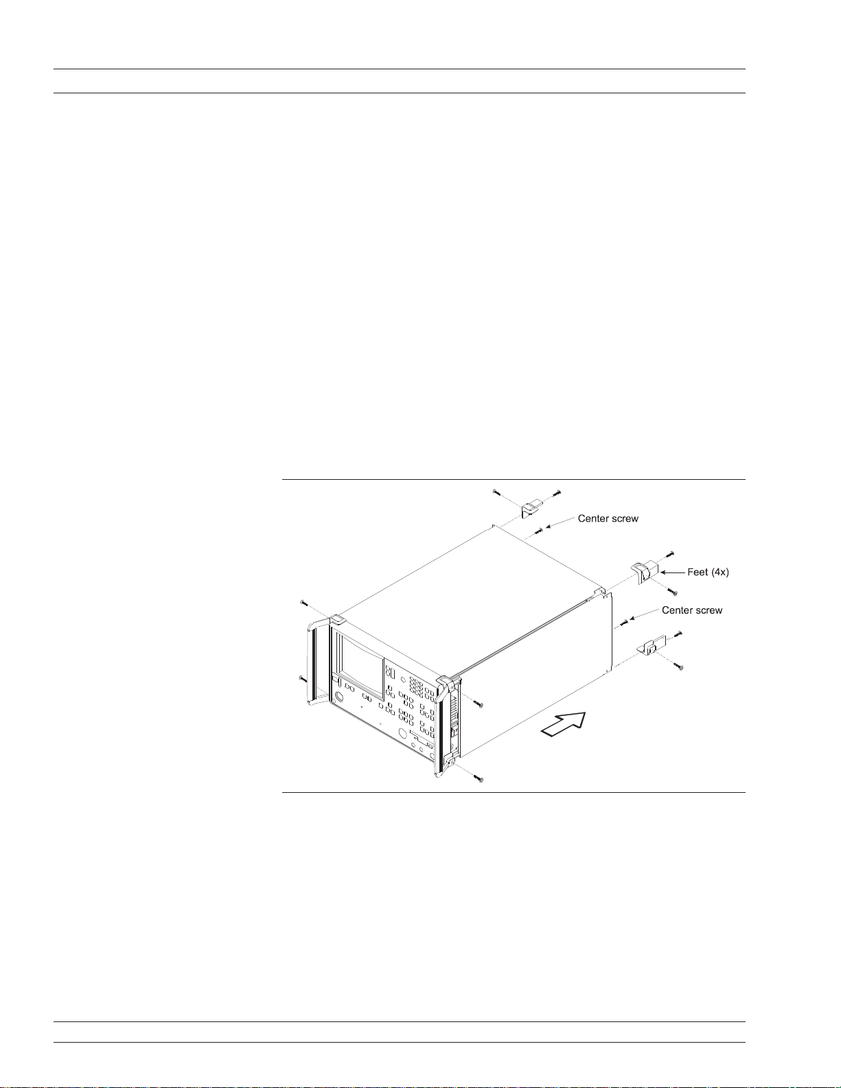
2-8 RACK MOUNT To install the Option 1 Rack Mount rails, refer to the below-listed pro-
cedure.
Step 1. Disconnect the line cord and any other attachments from the instru-
ment.
Step 2. Carefully place the instrument on its top (bottom-side up) on a secure
and stable work surface.
Step 3. Using a Phillips screwdriver, remove the two handles or four bumper
assemblies (and tilt bail, if installed) from the front of the unit, and
the four feet at the rear (Figure 2-1). Save the screws for later use.
Figure 2-1. Removing Cover
NOTES
q The green-headed screws are metric threads and must be used
only in the appropriately tapped holes
q The feet, handles, and bumpers are not reused in this application
Step 4. Remove the center screws from the rear of the left and right side cov
ers.
-
2-8 37xxxE OM
Page 29

INSTALLATION
RACK MOUNT
Step 5. Remove the two side carrying handle screws (if so equipped) located
under the plastic handle ends.
Step 6. Remove the left and right side covers. These side covers are not reused
in this application.
Step 7. Install the two Rack Mount Handles using the green-headed screws
removed earlier.
Refer to Figure 2-2, on the following page, for the remainder of the
assembly procedure.
Step 8. Secure the new left cover (2) from this retrofit kit to the left side chas-
sis of the instrument by installing the two center screws (6) to the top
and bottom and the previously removed center screw at the rear of the
left cover.
Step 9. Secure the slide assembly (4) to the left cover by installing the four
mounting screws (5) to the left chassis.
Figure 2-2. Mounting Rails
37xxxE OM 2-9
Page 30

STORAGE OR SHIPMENT INSTALLATION
Step 10. Secure the new right cover (3) from this retrofit kit to the right side
chassis of the instrument by installing the center screw (6) through
the center of the right side cover and the previously removed center
screw at the rear of the right side cover.
Step 11. Secure the slide assembly (4) to the right cover by installing the four
mounting screws (5) to the right chassis.
This completes the installation of the slide assembly.
2-9 STORAGE OR SHIPMENT The following paragraphs describe the procedure for preparing the
37xxxE for storage or shipment.
Preparation for Storage Preparing the 37xxxE for storage consists of cleaning the unit, packing
the inside with moisture-absorbing desiccant crystals, and storing the
unit in a temperature environment that is maintained between –40
and +70 degrees centigrade (–40 to 156 degrees Fahrenheit).
Preparation for Shipment To provide maximum protection against damage in transit, the 37xxxE
should be repackaged in the original shipping container. If this
container is no longer available and the 37xxxE is being returned to
Anritsu for repair, advise Anritsu Customer Service; they will send a
new shipping container free of charge. In the event neither of these
two options is possible, instructions for packaging and shipment are
given below.
Use a Suitable Container
Obtain a corrugated cardboard carton with a 275-pound test strength.
This carton should have inside dimensions of no less than six inches
larger than the instrument dimensions to allow for cushioning.
Protect the Instrument
Surround the instrument with polyethylene sheeting to protect the finish.
Cushion the Instrument
Cushion the instrument on all sides by tightly packing dunnage or
urethane foam between the carton and the instrument. Provide at
least three inches of dunnage on all sides.
Seal the Container
Seal the carton by using either shipping tape or an industrial stapler.
Address the Container
If the instrument is being returned to Anritsu for service, mark the
Anritsu address and your return address on the carton in one or more
prominent locations.
2-10 37xxxE OM
Page 31

Chapter 3
Network Analyzers,
A Primer
Table of Contents
3-1 INTRODUCTION ...................................3-3
3-2 GENERAL DESCRIPTION ..............................3-3
Source Module....................................3-4
Test Set Module ...................................3-4
Analyzer Module ..................................3-4
3-3 NETWORK ANALYZERS ...............................3-5
Page 32

Page 33

Chapter 3
TRANSMITTEDINCIDENT
TEST
DEVICE
Gain (dB)
Insertion Loss (dB)
Insertion Phase (degrees)
Transmission Coefficients (S12, S21)
Separation of Transmission
Components (Real and Imaginary)
Electrical Length (m)
Electrical Delay (s)
Deviation from Linear Phase (degrees)
Group Delay (s)
Network Analyzers,
A Primer
3-1 INTRODUCTION This section provides front panel operating and measurement applica
tion information and data. It includes discussions on the following top
ics:
System description
q
General discussion about network analyzers
q
Basic measurements and how to make them
q
q Error correction
q General discussion on test sets
3-2 GENERAL DESCRIPTION The Model 37xxxE Vector Network Analyzer System measures the
magnitude and phase characteristics of networks, amplifiers,
attenuators, and antennas. It compares the incident signal that leaves
the analyzer with either the signal that is transmitted through the
test device or the signal that is reflected from its input. Figure 3-1 and
Figure 3-2 illustrate the types of measurements that the 37xxxE can
make.
-
-
37xxxE OM 3-3
Figure 3-1. Transmission Measurements
Page 34

GENERAL DESCRIPTION NETWORK ANALYZERS, A PRIMER
REFLECTED
INCIDENT
TERMINATION
TEST
DEVICE
Return Loss (dB)
Reflection Coefficients (S11, S22)
Reflection Coefficients vs D istance
(Fourier Transform)
Impedance (R + j X)
SWR
Figure 3-2. Reflection Measurements
The 37xxxE is a self-contained, fully integrated measurement system
that includes an optional time domain capability. The system
hardware consists of the following:
q Analyzer
q Precision components required for calibration and performance
verification
q Optional use of Anritsu 67XXB, 68XXXA/B/C,or 69XXXA/B as a
second source
The 37xxxE internal system modules perform the following functions:
Source Module This module provides the stimulus to the device under test (DUT). The
frequency range of the source and test set modules establish the
frequency range of the system. The frequency stability of the source is
an important factor in the accuracy (especially phase accuracy) of the
network analyzer. Hence, the 37xxxE always phase locks the source to
an internal 10 MHz crystal reference.
Test Set Module The test set module routes the stimulus signal to the DUT and sam
ples the reflected and transmitted signals. The type of connector used
is important, as is the “Auto Reversing” feature. Auto Reversing means
that it applies the stimulus signal in both the forward and reverse di
rection. The direction is reversed automatically. This saves you from
having to reverse the test device physically to measure all four scatter
ing parameters (S-parameters). Frequency conversion (1st and 2nd
IFs) occurs in the test set module.
-
-
-
Analyzer Module The analyzer module down-converts, receives, and interprets the 3rd
IF signal for phase and magnitude data. It then displays the results of
this analysis on a large, 190 mm (7-1/2 inch) diagonal color display.
This display can show all four S-parameters simultaneously. In addi
tion to the installed display, you can also view the measurement re
sults on an external color monitor.
3-4 37xxxE OM
-
-
Page 35

NETWORK ANALYZERS, A PRIMER NETWORK ANALYZERS
SCALAR NE TWORK ANALYZERS
MICROWAVE
SIGNAL
MICROWAVE
DETECTOR
DETECTOR
OUTPUT
VOLTAGE
DETECTOR OUTPUT VOLTAGE I S PROPORTIONAL
TO SIGNAL AMPLITUDE.
3-3 NETWORK ANALYZERS We will begin this discussion with a subject familiar to most Anritsu
customers: scalar network analysis. After showing comparisons,we
will proceed to the fundamentals of network analyzer terminology and
techniques. This discussion serves as an introduction to topics pre
sented in greater detail later in this section. This discussion will touch
on new concepts that include the following:
Reference Delay
q
S-parameters: what they are and how they are displayed
q
Complex Impedance and Smith Charts
q
Scalar Analyzer Comparison
Network Analyzers do everything that scalar analyzers do except dis
play absolute power. In addition, they add the ability to measure the
phase characteristics of microwave devices and allow greater dynamic
range.
If all a Network Analyzer added was the capability for measuring
phase characteristics, its usefulness would be limited. While phase
measurements are important in themselves, it is the availability of
this phase information that unlocks many new features for complex
measurements. These features include Smith Charts, Time Domain,
and Group Delay. Phase information also allows greater accuracy
through vector error correction of the measured signal.
-
-
Figure 3-3. Scalar Analyzer
Detection
First, let us look at scalar network analyzers (SNAs). SNAs measure
microwave signals by converting them to a DC voltage using a diode
detector (Figure 3-3). This DC voltage is proportional to the magnitude
of the incoming signal. The detection process, however, ignores any
information regarding the phase of the microwave signal.
In a network analyzer, access is needed to both the magnitude and
phase of a microwave signal. There are several different ways to per
form the measurement. The method Anritsu employs (called Harmonic
Sampling or Harmonic Mixing) is to down-convert the signal to a lower
intermediate frequency (IF). This signal can then be measured directly
by a tuned receiver. The tuned receiver approach gives the system
greater dynamic range. The system is also much less sensitive to inter
fering signals, including harmonics.
-
37xxxE OM 3-5
Page 36

NETWORK ANALYZERS NETWORK ANALYZERS, A PRIMER
PHASE MEASUREMENT
TIME
TEST
SIGNAL
REFERENCE
SIGNAL
90
REFERENCE
SIGNAL
SPLITTER
TEST
SIGNAL
MICROWAVE
SOURCE
LONGER
PATH
LENGTH
PHASE
DETECTOR
A NETWORK ANALYZER IS A TUNED RECEIVER
TUNABLE
LOCAL
OSCILLATOR
INTERMEDIATE
FREQUENCY (IF)
MICROWAVE
SIGNAL
• GREATERDYNAMIC RANGE
• LESSSENSIVITY TO INTERFERINGSIGNALS
DUT
PHASE
DETECTOR
REFERENCE
SIGNAL
SPLITTER
TEST
SIGNAL
MICROWAVE
SOURCE
Vector Network Analyzer Basics
The network analyzer is a tuned receiver (Figure 3-4, left). The
microwave signal is down converted into the passband of the IF. To
measure the phase of this signal, we must have a reference to compare
it with. If the phase of a signal is 90 degrees, it is 90 degrees different
from the reference signal (Figure 3-5, left). The network analyzer
would read this as –90 degrees, since the test signal is delayed by 90
degrees with respect to the reference signal.
This phase reference can be obtained by splitting off some of the
microwave signal before the measurement (Figure 3-7, below).
Figure 3-4. Network Analyzer is
a Tuned Receiver
Figure 3-5. Signals with a
90 Degree Phase
Difference
a Length of Line
Replaces the DUT
Figure 3-6. Split Signal where
3-6 37xxxE OM
Figure 3-7. Splitting the Microwave Signal
The phase of the microwave signal after it has passed through the de
vice under test (DUT) is then compared with the reference signal. A
network analyzer test set automatically samples the reference signal,
so no external hardware is needed.
Let us consider for a moment that you remove the DUT and substitute
a length of transmission line (Figure 3-6, left). Note that the path
length of the test signal is longer than that of the reference signal.
Now let us see how this affects our measurement.
-
Page 37

NETWORK ANALYZERS, A PRIMER NETWORK ANALYZERS
REFERENCE
SIGNAL
SPLITTER
TEST
SIGNAL
MICROWAVE
SOURCE
PHASE
DETECTOR
LONGER BY
ONE WAVELENGTH
LENGTH (360 degrees)
REFERENCE
SIGNAL
SPLITTER
TEST
SIGNAL
MICROWAVE
SOURCE
SAME PATH
LENGTH -BUTWAVELENGTH
IS NOW SHORTER
1.1 WAVELENGTHS = 396 degrees
PHASE
DETECTOR
+180
+90
0
-90
-180
1.1
1.2
1.3
1.4
FREQUENCY,
GHz
MEASURED PHASE
Assume that we are making a measurement at 1 GHz and that the
difference in path-length between the two signals is exactly 1
wavelength. This means that test signal is lagging the reference signal
by 360 degrees (Figure 3-8). We cannot really tell the difference
between one sine wave maxima and the next (they are all identical), so
the network analyzer would measure a phase difference of 0 degrees.
Now consider that we make this same measurement at 1.1 GHz. The
frequency is higher by 10 percent so therefore the wavelength is
shorter by 10 percent. The test signal path length is now 0.1
wavelength longer than that of the reference signal (Figure 3-9). This
test signal is:
Figure 3-8. Split Signal where
Path Length Differs
by Exactly One
Wavelength
Figure 3-9. Split Signal where
Path Length is
Longer than One
1.1 X 360 = 396 degrees
This is 36 degrees different from the phase measurement at 1 GHz.
The network analyzer will display this phase difference as –36 de
-
grees.
The test signal at 1.1 GHz is delayed by 36 degrees more than the test
signal at 1 GHz.
You can see that if the measurement frequency is 1.2 GHz, we will get
a reading of –72 degrees, –108 degrees for 1.3 GHz, etc.(Figure 3-10).
There is an electrical delay between the reference and test signals.For
this delay we will use the common industry term of reference delay.
You also may hear it called phase delay. In older network analyzers
you had to equalize the length of the reference arm with that of the
test arm to make an appropriate measurement of phase vs. frequency.
To measure phase on a DUT, we want to remove this
phase-change-vs.-frequency due to changes in the electrical length.
This will allow us to view the actual phase characteristics. These char
acteristics may be much smaller than the phase change due to
electrical length difference.
-
Figure 3-10. Electrical Delay
37xxxE OM 3-7
Page 38

NETWORK ANALYZERS NETWORK ANALYZERS, A PRIMER
PHASE
DETECTOR
REFERENCE
SIGNAL
SPLITTER
TEST
SIGNAL
MICROWAVE
SOURCE
BOTH LINE
LENGTHS
NOW EQUAL
+180
+90
0
-90
-180
1.1
1.2
1.3
1.4
FREQUENCY,
GHz
MEASURED PHASE
SUBTRACT LINEAR
PHASE FROM
MEASURED PHASE
0
1.1
1.2
1.3
1.4
FREQUENCY,
GHz
+2
+1
-1
-2
RESULTANT PHASE
There are two ways of accomplishing this. The most obvious way is to
insert a length of line into the reference signal path to make both
paths of equal length (Figure 3-11, below). With perfect transmission
lines and a perfect splitter, we would then measure a constant phase
as we change the frequency. The problem using this approach is that
we must change the line length with each measurement setup.
Figure 3-12. Phase Difference
Increases Linearly
with Frequency
Figure 3-11. Split Signal where Paths are of Equal Length
Another approach is to handle the path length difference in software.
Figure 3-12 (left) displays the phase-vs.-frequency of a device. This
device has different effects on the output phase at different
frequencies. Because of these differences, we do not have a perfectly
linear phase response. We can easily detect this phase deviation by
compensating for the linear phase. The size of the phase difference
increases linearly with frequency so we can modify the phase display
to eliminate this delay.
The 37xxxE offers automatic reference delay compensation with the
push of a button. Figure 3-13 (left) shows the resultant measurement
when we compensate path length. In a system application you can
usually correct for length differences; however,the residual phase
Figure 3-13. Resultant Phase
with Path
Length
3-8 37xxxE OM
characteristics are critical.
Page 39

NETWORK ANALYZERS, A PRIMER NETWORK ANALYZERS
FORWARD
REFLECTION
REVERSE
REFLECTION
PORT 1 PORT 2
DUT
S12 REVERSE TRANSMISSION
PORT 1 PORT 2
S11 FORWARD
REFLECTION
S22 REVERSE
REFLECTION
S21 FORWARD TRANSMISSION
DUT
+180
0
-180
PHASE
FREQUENCY
Network Analyzer Measurements
Now let us consider measuring the DUT. Consider a two port device;
that is, a device with a connector on each end. What measurements
would be of interest?
First, we could measure the reflection characteristics at either end
with the other end terminated into 50 ohms. If we designate one end
as the normal place for the input that gives a reference. We can then
define the reflection characteristics from the reference end as forward
reflection, and those from the other end as reverse reflection
(Figure 3-14).
Second, we can measure the forward and reverse transmission
Figure 3-14. Forward and
Reverse
Measurements
characteristics. However, instead of saying “forward,”“reverse,”
“reflection,”and “transmission” all the time, we use a shorthand. That
is all that S-parameters are, a shorthand! The “S” stands for
scattering. The second number is the device port that the signal is
being injected into, while the first is the device port that the signal is
leaving.S
, therefore, is the signal being injected into port 1 relative
11
to the signal leaving port 1. The four scattering parameters
(Figure 3-15) are:
Figure 3-15. S-parameters
Figure 3-16. Linear
37xxxE OM 3-9
Phase-with-frequen
cy Waveform
q S
Forward Reflection
11
q S
Forward Transmission
21
q S
Reverse Reflection
22
q S
Reverse Transmission
12
S-parameters can be displayed in many ways.An S-parameter consists
of a magnitude and a phase. We can display the magnitude in dB, just
like a scalar network analyzer. We often call this term log magnitude.
We can display phase as “linear phase” (Figure 3-16). As discussed
earlier, we can’t tell the difference between one cycle and the next.
Therefore, after going through 360 degrees we are back to where we
began. We can display the measurement from –180 to +180 degrees.
The –180 to +180 approach is more common. It keeps the display
discontinuity removed from the important 0 degree area used as the
phase reference.
Page 40

NETWORK ANALYZERS NETWORK ANALYZERS, A PRIMER
-90
180
90
0
POLAR DISPLAY
50
INDUCTIVE
CAPACITIVE
SMITH CHART
There are several ways in which all the information can be displayed
on one trace. One method is a polar display (Figure 3-17). The radial
parameter (distance from the center) is magnitude. The rotation
around the circle is phase. We sometimes use polar displays to view
transmission measurements, especially on cascaded devices (devices in
series). The transmission result is the addition of the phase and log
magnitude (dB) information of each device’s polar display.
Figure 3-17. Polar Display
Figure 3-18. Smith Chart
As we have discussed, the signal reflected from a DUT has both mag
nitude and phase. This is because the impedance of the device has
both a resistive and a reactive term of the form r+jx. We refer to the r
as the real or resistive term, while we call x the imaginary or reactive
term. The j, which we sometimes denote as i, is an imaginary number.
It is the square root of –1. If x is positive, the impedance is inductive; if
x is negative, the impedance is capacitive.
The size and polarity of the reactive component x is important in im
pedance matching. The best match to a complex impedance is the com
plex conjugate. This complex-sounding term simply means an impedance with the same value of r and x, but with x of opposite polarity.
This term is best analyzed using a Smith Chart (Figure 3-18), which is
a plot of r and x.
To display all the information on a single S-parameter requires one or
two traces, depending upon the format we want. A very common
requirement is to view forward reflection on a Smith Chart (one trace)
while observing forward transmission in Log Magnitude and Phase
(two traces). Let us see how to accomplish this in the 37xxxE.
The 37xxxE has four channels. Each channel can display a complete
S-parameter in any format on either one or two traces. All four
S-parameters can be seen simultaneously in any desired format. A
total of eight traces can be viewed at the same time. While this is a lot
of information to digest, the 37xxxE’s large color display makes
recognizing and analyzing the data surprisingly easy.
-
3-10 37xxxE OM
Page 41

NETWORK ANALYZERS, A PRIMER NETWORK ANALYZERS
VECTOR ERROR CORRECTION
THEN THE RESULTANT VECTOR IS
APPLIED MATHEMATICALLY, HENCE
MAGNITUDE AND PHASE OF
EACH ERROR SIGNAL IS MEASURED
MAG
PHASE
Another important parameter we can measure when phase informa
tion is available is group delay. In linear devices, the phase change
through the DUT is linear-with-frequency. Thus, doubling the fre
quency also doubles the phase change. An important measurement, es
pecially for communications system users, is the rate of
change-of-phase-vs.-frequency (group delay). If the rate of
phase-change-vs.-frequency is not constant, the DUT is nonlinear. This
nonlinearity can create distortion in communications systems.
Measurement Error Correction
Since we can measure microwave signals in both magnitude and
phase, it is possible to correct for six major error terms:
Source Test Port Match
q
Load Test Port Match
q
Directivity
q
q Isolation
q Transmission Frequency Response
q Reflection Frequency Response
We can correct for each of these six error terms in both the forward
and reverse directions, hence the name 12-term error correction. Since
12-term error correction requires both forward and reverse measurement information, the test set must be reversing. “Reversing” means
that it must be able to apply the measurement signal in either the forward or reverse direction.
-
Figure 3-19. Magnitude and
37xxxE OM 3-11/3-12
Phase
To accomplish this error correction, we measure the magnitude and
phase of each error signal (Figure 3-19). Magnitude and phase infor
mation appear as a vector that is mathematically applied to the mea
-
-
surement signal. This process is termed vector error correction.
Summary
A vector network analyzer is similar to a scalar network analyzer. The
major difference is that it adds the capability for measuring phase as
well as amplitude. With phase measurements comes scattering, or
S-parameters, which are a shorthand method for identifying forward
and reverse transmission and reflection characteristics. The ability to
measure phase introduces two new displays,polar and Smith Chart. It
also adds vector error correction to the measurement trace. With vec
tor error correction, errors introduced by the measurement system are
compensated for and measurement uncertainty is minimized. Phase
measurements also add the capability for measuring group delay,
which is the rate of change-of-phase vs.frequency (group delay). All in
all, using a network analyzer provides for making a more complete
analysis of your test device.
Page 42

Page 43

Chapter 4
Front Panel Operation
Table of Contents
4-1 INTRODUCTION ...................................4-3
4-2 KEY-GROUPS .....................................4-3
4-3 CALIBRATION KEY-GROUP ............................4-10
4-4 SAVE/RECALL MENU KEY.............................4-20
4-5 MEASUREMENT KEY-GROUP ..........................4-21
4-6 CHANNELS KEY-GROUP..............................4-24
4-7 DISPLAY KEY-GROUP ...............................4-25
4-8 ENHANCEMENT KEY-GROUP...........................4-29
4-9 HARD COPY KEY-GROUP .............................4-31
4-10 SYSTEM STATE KEY-GROUP ...........................4-33
4-11 MARKERS/LIMITS KEY-GROUP ..........................4-36
4-12 STORAGE INTERFACE ...............................4-40
Disk Files......................................4-40
Disk File Output Device..............................4-41
Formatting a Data File Drive ...........................4-41
Copying Data Files From Drive to Drive .....................4-41
Recovering From Drive Write/Read Errors....................4-41
4-13 COMMAND LINE ..................................4-42
Create Directory ..................................4-42
List Directory ...................................4-42
Change Directory .................................4-42
Delete Files.....................................4-42
Remove Directory .................................4-43
Copy Files .....................................4-43
Conventions ....................................4-43
Page 44

Calibration
Menu
Hard Copy
Markers/Limits
System State
Local Lockout
SRQ
Listen
Tal k
Remote
GPIB
Power
Default
Program
Utility
Menu
Begin
Cal
Apply
Cal
Save/
Recall
Menu
Start
Print
Stop
Print
Menu
Limits
Marker
Menu
Readout
Marker
Graph
Type
Set
Scale
Auto
Scale
S
Params
Ref
Plane
Trace
Memory
Channel
Menu
Ch 1
Ch 2
Ch 3
Ch 4
Option
Menu
Video
IF BW
Avg/
Smooth
Menu
Trace
Smooth
Average
Setup
Menu
Data
Points
Hold
Domain
Appl
Enter
789
4
5
6
12
3
0
.
-
MHz
nsX1cm
GHz
10
3
us
m
kHz
ps
10
-3
mm
Clear
Ret Loc
Measurement
Enhancement
Channels
Data Entry
Display
Port 1
Source
Port 2
Source
Port 2
Port 2Port 1
Bias Input
Port 1
CAUTION
+30 dBm MAX
40 VDC MAX
AVOIDSTATIC
DISCHARGE
CAUTION
+30 dBm MAX
40 VDC MAX
AVOIDSTATIC
DISCHARGE
a
2
a
1
b
1
b
2
!
+30 dBm
!
0.5AMAX
!
+24 dBm
!
+30 dBm
!
+24 dBm
!
+27 dBm
!
+27 dBm
!
+20 dBm
!
+20 dBm
20
13
12
76
5
4
3
2
1
18
17
16
15
14
11
10
9
8
19
21
22
23
24
Figure 4-1. Model 37xxxE Front Panel
Page 45

Chapter 4 Front Panel Operation
4-1 INTRODUCTION This chapter describes the front panel keys, controls, and menus. The
chapter is organized into an overall description of the front panel
key-groups and detailed descriptions of individual keys within the
key-groups.
4-2 KEY-GROUPS The following pages provide descriptions of the front panel key-groups
illustrated in Figure 4-1 on the previous page.
Index 1. LCD display: Displays any or all of the four mea
surement channels, plus menus.
Index 2. Power: Turns the 37xxxE on and off.When on, the
operating program runs a self test then recalls the
parameters and functions in effect when previously
powered down.
Index 3. GPIB Indicators:
Remote: Lights when the 37xxxE switches to
remote (GPIB) control. It remains lit until the unit
returns to local control.
Talk: Lights when you address the 37xxxE to talk
and remains lit until unaddressed.
Listen: Lights when you address the 37xxxE to
listen and remains lit until unaddressed.
SRQ: Lights when the 37xxxE sends a Service
Requests (SRQ) to the external controller. The LED
remains lit until the 37xxxE receives a serial poll or
until the controller resets the SRQ function.
-
Local Lockout: Lights when a local lockout
message is received. The LED remains lit until the
message is rescinded. When lit, you cannot return
the 37xxxE to local control via the front panel.
37xxxE OM 4-3
Page 46

KEY-GROUPS FRONT PANEL OPERATION
Index 4. System State Keys: (Refer to section 4-10,
page 4-33, for details and menu flow diagrams.)
Default Program: Resets the front panel to the fac
tory-preset state and displays Menu SU1 or SU3
(Appendix A). Pressing this key in conjunction with
the “0” or “1” key resets certain internal memories
and front panel key states (refer to sections 4-5 and
4-10).
NOTE
Use of the Default Program key will destroy
front panel and calibration setup data, un
less they have been saved to disk.
Utility Menu: Displays the first in a series of menus
that let you perform storage and other utility-type
functions and operations.
Index 5. Port 1 Test Connector: Provides an input test con-
nection for the device-under-test (DUT).
Index 6. Port 1 Source Loop: Provides for inserting addi-
tional amplification on Port 1 before the coupler.
Index 7. Calibration Keys: (Refer to section 4-3, page 4-10,
for details and menu flow diagrams.)
-
-
Begin Cal: Calls up the first in a sequence of
menus that guide you through a measurement cali
bration. Refer to section 4-3 for a detailed discussion
of the calibration keys, indicators, and menus.
Apply Cal: Turns on and off the applied error cor
rection and tune mode.
Index 8. a1 Loop: Provides direct access to Reference A
channel on Port 1 over the entire frequency range.
Refer to the front panel for damage levels.
Index 9. a2 Loop: Provides direct access to Reference B
channel on Port 2 over the entire frequency range.
Refer to the front panel for damage levels.
Index 10. b1 Loop: Provides direct access to Test A channel
on Port 1 over the entire frequency range. Refer to
the front panel for damage levels.
Index 11. b2 Loop: Provides direct access to Test B channel
on Port 2 over the entire frequency range. Refer to
the front panel for damage levels.
-
-
4-4 37xxxE OM
Page 47

FRONT PANEL OPERATION KEY-GROUPS
Index 12. Save/Recall Menu Key: Displays the first of several
menus that let you save the current calibration or
front panel setup or recall a previously saved cali
bration or setup. Refer to section 4-4, page 4-20, for
menu flow diagram.
Index 13. Markers/Limits Keys: (Refer to section 4-11,
page 4-36, for details and menu flow diagrams.)
Marker Menu: Displays the first in a series of
menus that let you set and manipulate marker fre
quencies, times, and distances.
Readout Marker: Displays a menu that lists all of
the active markers. If no markers are active, the
marker menu is displayed.
-
-
Limits: Displays one of the menus that let you ma
nipulate the limit lines.
Index 14. Port 2 Source: Provides for inserting additional
amplification on Port 2 before the coupler.
Index 15. Hard Copy Keys: (Refer to section 4-9, page 4-31,
for details and menu flow diagrams.)
Menu: Displays option menus that let you define
what will happen each time you press the Start
Print key. The displayed menu also selects disk I/O
operations.
Start Print: Tells the printer or plotter to start out
put based on the current selections.
Stop Print: Immediately stops printing the data,
clears the print buffer, and sends a form-feed com
mand to the printer.
Index 16. Port 2 Test Connector: Provides an input test con
nection for the device-under-test (DUT).
-
-
-
-
37xxxE OM 4-5
Page 48

KEY-GROUPS FRONT PANEL OPERATION
Index 17. Display Keys: (Refer to section 4-7, page 4-25, for
details and menu flow diagrams.)
Graph Type: Displays the two menus that let you
choose the graph type for the active channel.
Set Scale: Displays the appropriate scaling menu,
based on the graph type for the active channel.
Auto Scale: Automatically scales the active chan
nel for optimum viewing.
S Params: Displays Menu SP (Appendix A), which
lets you choose between S11, S12, S21, or S22. You
may display the same parameter on two or more
channels.
Ref Plane: Displays the first of two menus that let
you set the reference plane for the active channel in
time or distance. For a correct distance readout, you
must set the dielectric constant to the correct value.
Refer to the discussion in menu RD2 (Appendix A).
Trace Memory: Displays the menus that let you do
any of the following. (1) Store the measured data in
memory. (2) View the stored data. (3) Add, subtract,
multiply, or divide the measured data from the
stored data (normalize to the stored memory). (4)
View both the measured and the stored data simultaneously on the active channel. (5) Store/Recall
saved data to disk. Four memories exist—one for
each channel. This lets you normalize the data in
each channel independently. The LED on this but
ton lights when the active channel is displaying
memory data or measurement data normalized to
memory.
-
-
Index 18. Bias Input Connectors:
Port 1: Provides for supplying a bias voltage for the
Port 1 input.
Port 2: Provides for supplying a bias voltage for the
Port 2 input.
4-6 37xxxE OM
Page 49

FRONT PANEL OPERATION KEY-GROUPS
Index 19. Enhancement Keys: (Refer to section 4-8,
page 4-29 for details and menu flow diagrams.)
Option Menu: Displays a series of menus showing
the choice of optional features.
Video IF BW: Displays a menu that lets you chose
between 10 kHz, 1 kHz, 100 Hz, or 10 Hz intermedi
ate frequency (IF) bandwidth filters.
Avg/Smooth Menu: Displays a menu that lets you
enter values for Averaging and Smoothing.
Trace Smooth: Turns the trace smoothing function
on and off.
Average: Turns the average function on and off.
Index 20. USB Connector: Provides a USB connector used to
store selected front panel setups and calibrations.
-
NOTE
The USB interface CANNOT be used for
Printers and other USB peripherals. Refer
to Section 4-12 for storage information.
37xxxE OM 4-7
Page 50

KEY-GROUPS FRONT PANEL OPERATION
Index 21. Channels Keys: (Refer to section 4-6, page 4-24, for
details and menu flow diagrams.)
Channel Menu: Displays a menu that lets you se
lect the format for the number of channels dis
played.
Ch 1: Makes Channel 1 the active channel. The ac
tive channel is the one acted on by the keys in the
Display section. Only one channel can be active at
any one time.
Ch 2: Makes Channel 2 the active channel.
Ch 3: Makes Channel 3 the active channel.
Ch 4: Makes Channel 4 the active channel.
Index 22. Measurement Keys: (Refer to section 4-5, page 4-21
for details and menu flow diagrams.)
Setup Menu: Displays the first of several menus
that let you select functions affecting measurements.
Data Points: Displays a menu that lets you select
between 1601, 801, 401, 201, 101, or 51 data points.
-
-
-
Hold: Toggles the instrument in and out of the hold
mode; or it triggers a sweep, depending on the func
tion selected in menu SU4 (Appendix A).
Domain: Displays the first in a series of menus that
let you set the Time Domain display parameters.
(This key is only active if your 37xxxE is equipped
with the Time Domain option.)
•
If already in the Domain menus, pressing this
key will return to the first menu in the sequence.
•
If in the Domain menus and another (non-time
domain) menu is displayed by pushing a menu
key, the last displayed domain menu redisplays
when the Domain key is next pressed.
Applications Menu: Displays the first in a series of
menus that provide instructions for adapter removal
and gain compression.
-
4-8 37xxxE OM
Page 51

FRONT PANEL OPERATION KEY-GROUPS
Index 23. Data Entry Keys:
Rotary Knob: Used to alter measurement values
for the active parameter (Start Frequency, Stop Fre
quency, Offset, etc.).
Keypad: Provides for entering values for the active
parameter. The active parameter is the one to which
the menu cursor is pointing.
MHz/X1/ns/cm: Terminates a value entered on the
keypad in the units shown—that is; megahertz for
frequency, unity for dimensionless or angle entries,
nanoseconds for time, or centimeters for length.
-
GHz/10
keypad in the units shown—that is; gigahertz for
frequency, 1´10
3
/ms/m: Terminates a value entered on the
3
power for dimensionless or angle
entries, microseconds for time, or meters for length.
kHz/10
keypad in the units shown—that is; kilohertz for
frequency, 1´10
-3
/ps/mm: Terminates a value entered on the
-3
for dimensionless or angle entries,
picoseconds for time, or millimeters for length.
•
Clear/Ret Loc: Local (Non-GPIB) Mode: (1) The
key clears entries not yet terminated by one of
the terminator keys above, which allows the previously displayed values to redisplay. Or (2) the
key turns off the displayed menu and expands
the data area to fill the entire screen, if you have
not made any keypad entries needing termina
-
tion.
•
GBIB Mode: The key returns the instrument to
local (front panel) control, unless the controller
has sent a local lockout message (LLO) over the
bus.
Index 24. Menu Keys:
Arrow Keys: Moves the menu cursor up and down
to select items appearing in the menu area of the
LCD.
Enter: Implements the menu selection chosen using
the arrow keys.
37xxxE OM 4-9
Page 52

CALIBRATION KEY-GROUP FRONT PANEL OPERATION
.
-
Measurement
Enhancement
Channels
Display
Begin
Cal
Apply
Cal
MENU CAL_APPLIED
APPLY
CALIBRATION
PRESS <ENTER>
TO TURN ON/OFF
FULL 12-TERM
(S11, S21
X22, S12
APPLY ON (OFF)
CALIBRATION
TUNE MODE ON (OFF)
NO. OF FWD (REV)
SWEEPS BETWEEN
REV (FWD) SWEEPS
XXXXX SWEEPS
(XXXXX (REMAINING)
PRESS <APPLY CAL>
TO TURN ON/OFF
4-3 CALIBRATION
KEY-GROUP
The Calibration keys (Begin Cal and Apply Cal, below) are described
below. The calibration menus are diagramed according to the method
of calibration performed: Standard, Offset-Short, TRM or LRL/LRM.
The menu sequencing is complex and looping and can be said to have
two parts: setup and calibration. The setup flow for the four calibra
tion methods is diagramed in Figures 4-3 through 4-6. Each setup flow
chart leads to the main calibration sequence, which is diagramed in
Figure 4-6. A full description of each menu is provided in Appendix A,
where the menus are arranged in alphabetical order by call letter (C1,
C2, C3, etc).
Begin Cal Key: This key displays a menu that lets you initiate the
calibration sequence. That is, to begin a sequence of steps that corrects
for errors inherent in a measurement setup.
Apply Cal Key: This key displays a menu (below) that lets you turn
on and off the error correction that may be applied to the displayed
channel(s) using the currently valid error-correction indicator.Additionally, the menu lets you turn the tune mode on and off and change
the number of forward sweeps between reverse sweeps (or reverse
sweeps between forward sweeps).
NOTE
Pressing the Clear key while in a calibration setup or sequencing will let you abort the calibration and return to
the first setup menu. Pressing the Setup Menu key will do
the same, but without requesting confirmation.
Figure 4-2. Calibration Key Group Menu
4-10 37xxxE OM
Page 53

FRONT PANEL OPERATION CALIBRATION KEY-GROUP
Standard Calibration Setup Flow—Description
1. Pressing the Begin Cal key calls Menu C11.
2. With one exception, the flow is from left to right in the direction of
the arrow head. The exception occurs in Menu C1, for the TIME
DOMAIN choice. Here the flow direction reverses to Menu C2C
then returns to a left-to-right flow on to Menu C3 or C3D.
3. Arrowheads that point both left and right indicate that the flow
returns to the right-most menu after a choice had been made.
4. The group of menus to the left of Menu C3 and C3D are the initial
selection set and are essentially the same for all four calibration
types: Standard, Offset-Short, TRM, and LRL/LRM.
5. The group of menus that follow Menu C3 or C3D are, for the most
part, type specific. The selection of Menu C3 or C3D depends upon
the choice made in Menu C11A: COAXIAL or MICROSTRIP. For
the Standard Calibration, the WAVEGUIDE selection in Menu
C11A is not used.
37xxxE OM 4-11
Page 54

CALIBRATION KEY-GROUP FRONT PANEL OPERATION
M E N U C 1 1 A
N E X T C A L S T E P
C A L M E T H O D
L R L / L R M
C O A X I A L
W A V E G U I D E
M I C R O S T R I P
C H A N G E
C A L M E T H O D
A N D L I N E T Y P E
S O L T ( S T A N D A R D )
P R E S S
< E N T E R >
T O S E L E C T
T R A N S M I S S I O N
L I N E T Y P E
M E N U C 1 7
E N T E R
R E F E R E N C E
I M P E D A N C E
P R E S S < E N T E R >
W H E N C O M P L E T E
R E F E R E N C E
I M P E D A N C E
X X X . X X X
9
B e g i n
C a l
T o C a l
S e q * *
C O A X
( S e e M e n u C 1 1 A )
M I C R O S T R I P
( S e e M e n u C 1 1 A )
M E N U C 5 D
S E L E C T U S E
O F I S O L A T I O N
I N C A L I B R A T I O N
I N C L U D E
I S O L A T I O N
( S T A N D A R D )
E X C L U D E
I S O L A T I O N
P R E S S < E N T E R >
T O S E L E C T
M E N U C 5 C
P R E S S < E N T E R >
T O S E L E C T
S E L E C T
R E F L E C T I O N O N L Y
C A L I B R A T I O N T Y P E
P O R T 1 O N L Y
( S 1 1 )
P O R T 2 O N L Y
( S 2 2 )
B O T H P O R T S
( S 1 1 , S 2 2 )
S E L E C T
C A L I B R A T I O N
D A T A P O I N T S
N O R M A L
( 1 6 0 1 P O I N T S
M A X I M U M
C . W .
( 1 P O I N T )
N - D I S C R E T E
F R E Q U E N C I E S
( 2 T O 1 6 0 1
P O I N T S )
T I M E D O M A I N
( H A R M O N I C )
P R E S S < E N T E R >
T O S E L E C T
M E N U C 1
T E S T S I G N A L S
S T A R T C A L
C O N F I R M
C A L I B R A T I O N
P A R A M E T E R S
P O R T 1 C O N N
X X X X X X X X
P O R T 2 C O N N
X X X X X X X X
R E F L E C T I O N
P A I R I N G
X X X X X X
L O A D T Y P E
X X X X X X X X
T H R O U G H L I N E
P A R A M E T E R S
R E F E R E N C E
I M P E D A N C E
P R E S S < E N T E R >
T O S E L E C T
O R C H A N G E
M E N U C 3
M E N U C 6
S E L E C T
T Y P E O F L O A D
S L I D I N G L O A D
( M A Y A L S O
R E Q U I R E A
B R O A D B A N D
F I X E D L O A D )
P R E S S < E N T E R >
T O S E L E C T
B R O A D B A N D
F I X E D L O A D
M E N U C 2 B
P R E S S < E N T E R >
T O S E L E C T
S I N G L E P O I N T
C . W . C A L I B R A T I O N
C . W . F R E Q
X X . X X X X X X X X G H z
N E X T C A L S T E P
M E N U C 2 0
E N T E R
T H R O U G H L I N E
P A R A M E T E R S
O F F S E T L E N G T H
X X X X X X m m
P R E S S < E N T E R >
W H E N C O M P L E T E
T H R O U G H L I N E
I M P E D A N C E
X . X X X X
9
T o C a l
S e q * *
T o C a l
S e q * *
T o M e n u
S U 1 / S U 3 *
F U L L 1 2 - T E R M
S E L E C T
C A L I B R A T I O N T Y P E
1 P A T H
2 P O R T
T R A N S M I S S I O N
F R E Q U E N C Y
R E S P O N S E
R E F L E C T I O N
O N L Y
P R E S S < E N T E R >
T O S E L E C T
M E N U C 5
F O R W A R D P A T H
( S 1 1 , S 2 1 )
P R E S S < E N T E R >
T O S E L E C T
S E L E C T
1 P A T H 2 P O R T
C A L I B R A T I O N T Y P E
R E V E R S E P A T H
( S 2 2 , S 1 2 )
M E N U C 5 A
S E L E C T
T R A N S M I S S I O N
F R E Q R E S P O N S E
C A L I B R A T I O N T Y P E
F O R W A R D P A T H
( S 2 1 )
M E N U C 5 B
P R E S S < E N T E R >
T O S E L E C T
R E V E R S E P A T H
( S 1 2 )
B O T H P A T H S
( S 2 1 , S 1 2 )
M E N U C 2 C
C A L I B R A T I O N
R A N G E
H A R M O N I C C A L
F O R T I M E D O M A I N
U S I N G A B O V E
S T A R T A N D S T O P
W I L L R E S U L T I N
X X X D A T A P O I N T S
X X X . X X X X X X X X X G H z
T R U E S T O P F R E Q
S T A R T ( S T E P )
X X X . X X X X X X X X X G H z
A P P R O X I M A T E S T O P
X X X . X X X X X X X X X G H z
N E X T C A L S T E P
P R E S S < E N T E R >
T O S E L E C T
M E N U C 2 D
D I S C R E T E F I L L
C L E A R A L L
P R E S S < E N T E R >
T O S E L E C T
I N P U T S T A R T ,
I N C R , P O I N T S ,
T H E N S E L E C T
" F I L L R A N G E "
S T A R T F R E Q
X X X . X X X X X X X X X G H z
I N C R E M E N T
X X X . X X X X X X X X X G H z
N U M B E R O F P T S
X X X P O I N T ( S )
S T O P F R E Q
X X X . X X X X X X X X X G H z
F I L L R A N G E
( X X X E N T E R E D )
I N D I V I D U A L
F R E Q I N S E R T
F I N I S H E D
N E X T C A L S T E P
T E S T S I G N A L S
S T A R T C A L
C O N F I R M
C A L I B R A T I O N
P A R A M E T R S
P O R T 1
O P E N / S H O R T
L O A D I M P E D A N C E
X X X X X X
T H R O U G H L I N E
P A R A M E T E R S
X X X X X X X X
M I C R O S T R I P
P A R A M E T E R S
X X X X X X X X X X X
P R E S S < E N T E R >
T O S E L E C T
O R C H A N G E
M E N U C 3 D
P O R T 2
O P E N / S H O R T
R E F L E C T I O N
P A R I N G
M E N U C 4 _ P 1 o r _ P 2
S E L E C T P O R T X
C O N N E C T O R T Y P E
T Y P E N ( M )
T Y P E N ( F )
T Y P E N ( M ) 7 5 W
T Y P E N ( F ) 7 5 W
7 / 1 6 ( M )
7 / 1 6 ( F )
T N C ( M )
T N C ( F )
2 . 4 m m ( M )
2 . 4 m m ( F )
S P E C I A L ( M )
S P E C I A L ( F )
U S E R D E F I N E D
M O R E
S E L E C T P O R T X
C O N N E C T O R T Y P E
P R E S S < E N T E R >
T O S E L E C T
M E N U C 4 A _ P 1 o r _ P 2
P R E S S < E N T E R >
W H E N C O M P L E T E
O F F S E T L E N G T H
+ X X . X X X X m m
E N T E R T H E
O F F S E T L E N G T H
T E R M 4 - C 3
+ X X X . X X e - 4 5
T E R M 3 - C 2
+ X X X . X X e - 3 6
T E R M 2 - C 1
+ X X X . X X e - 2 7
T E R M 1 - C 0
+ X X . X X e - 1 5
E N T E R T H E
C A P A C I T A N C E
C O E F F I C I E N T S
P O R T X
O P E N D E V I C E
M E N U C 1 2 _ P 1 o r _ P 2
P R E S S < E N T E R >
W H E N C O M P L E T E
O F F S E T L E N G T H
X X . X X X X m m
P O R T X
S H O R T D E V I C E
E N T E R T H E
I N D U C T A N C E
C O E F F I C I E N T S
M E N U C 1 2 A _ P 1 o r _ P 2
M E N U C 1 6
1 0 M I L K I T
1 5 M I L K I T
2 5 M I L K I T
U S E R D E F I N E D
S E L E C T
M I C R O S T R I P
K I T T O U S E
P R E S S < E N T E R >
T O S E L E C T
M E N U C 1 6 A
E N T E R
M I C R O S T R I P
P A R A M E T E R S
P R E S S < E N T E R >
W H E N C O M P L E T E
W I D T H O F
S T R I P
X X . X X X X m m
T H I C K N E S S O F
S U B S T R A T E
X X X X . X X X X m m
S U B S T R A T E
D I E L E C T R I C
X . X X
E F F E C T I V E
D I E L E C T R I C
X . X X
( R E C O M M E N D E D
1 . 0 0 )
Z c
X . X X X p
9
A
A
A o r B
B
M E N U C 2 A
P R E V I O U S M E N U
I N P U T A F R E Q ,
P R E S S < E N T E R >
T O I N S E R T
N E X T F R E Q .
X X X . X X X X X X X X X G H z
X X X F R E Q S .
E N T E R E D ,
L A S T F R E Q W A S
X X X . X X X X X X X X X G H z
A U T O I N C R O N ( O F F )
X X X . X X X X X X X X X G H z
P R E S S < E N T E R >
T O S E L E C T
O R T U R N O N / O F F
I N S E R T
I N D I V I D U A L
F R E Q U E N C I E S
T o M e n u
C A L _ S U 2 *
T o M e n u
C A L _ S U 2 *
C A L F R E Q R A N G E
C E N T E R
X X X . X X X X X X X X X G H z
S P A N
X X X . X X X X X X X X X G H z
S E T S T A R T / S T O P
X X X D A T A P O I N T ( S )
X X . X X X X X X X X X G H z
S T E P S I Z E
M E N U C 2 _ C E N T E R
P R E S S < E N T E R >
T O S E L E C T
N U M O F D A T A P O I N T S
1 6 0 1 M A X P T S
8 0 1 M A X P T S
4 0 1 M A X P T S
2 0 1 M A X P T S
1 0 1 M A X P T S
5 1 M A X P T S
N E X T C A L S T E P
S T A R T
X X X . X X X X X X X X X G H z
X X X D A T A P O I N T S
X X X . X X X X X X X X X G H z
S T E P S I Z E
P R E S S < E N T E R >
T O S E L E C T
S T O P
X X X . X X X X X X X X X G H z
N U M O F D A T A P O I N T S
1 6 0 1 M A X P T S
8 0 1 M A X P T S
4 0 1 M A X P T S
2 0 1 M A X P T S
1 0 1 M A X P T S
5 1 M A X P T S
N E X T C A L S T E P
M E N U C 2
C A L F R E Q R A N G E
S E T C E N T E R / S P A N
T E R M 1 - L 0
- X X X X . X X e - 1 2
T E R M 2 - L 1
- X X X X . X X e - 2 4
T E R M 3 - L 2
- X X X X . X X e - 3 3
T E R M 4 - L 3
- X X X X . X X e - 4 2
E N T E R T H E
O F F S E T L E N G T H
M E N U C 6 A
B R O A D B A N D L O A D
P A R A M E T E R S
P R E S S < E N T E R >
W H E N C O M P L E T E
I M P E D A N C E
X X . X X X
9
I N D U C D A N C E
X X . X X X p H
M E N U C 1 1
B E G I N C A L I B R A T I O N
N E X T C A L S T E P
K E E P E X I S T I N G
C A L D A T A
C H A N G E C A L
M E T H O D A N D
L I N E T Y P E
P R E S S < E N T E R >
T O S E L E C T
R E P E A T
P R E V I O U S C A L
C A L M E T H O D
S T A N D A R D
T R A N S M I S S I O N
L I N E T Y P E :
X X X X X X X X
A U T O C A L
S S L T ( D O U B L E
O F F S E T S H O R T
W I T H L O A D )
S S S T ( T R I P L E
O F F S E T S H O R T )
T R M
K - C O N N ( M )
K - C O N N ( F )
V - C O N N ( M )
V - C O N N ( F )
W 1 - C O N N ( M )
W 1 - C O N N ( F )
S M A ( M )
S M A ( F )
G P C - 3 . 5 ( M )
G P C - 3 . 5 ( F )
G P C - 7
U S E R D E F I N E D
M O R E
P R E S S < E N T E R >
T O S E L E C T
O R C H A N G E
M E N U C 1 3
S E L E C T
R E F L E C T I O N
P A I R I N G
M I X E D
( O P E N - S H O R T
S H O R T - O P E N )
M A T C H E D
( O P E N - O P E N
S H O R T - S H O R T )
P R E S S < E N T E R >
T O S E L E C T
C
C
M E N U C 4 B
P R E S S < E N T E R >
T O S E L E C T
S E L E C T P O R T X
O P E N & S H O R T
S P E C I A L ( M )
S P E C I A L ( F )
U S E R D E F I N E D
T o M e n u
C 1 3 A o r B * * *
* Setup Menu SU1/SU3 – See Figure 4-6
** Cal Seq (Calibration Sequence) – See Figure 4-5
*** Reflection Pairing Menu C13A or C13B – See Figure 4-4
4-12 37xxxE OM
Figure 4-3. Menu Sequencing, Standard Calibration
Page 55

FRONT PANEL OPERATION CALIBRATION KEY-GROUP
SSLT and SSST (Offset-Short)
Calibration Setup Flow—Description
1. Pressing the Begin Cal key calls Menu C13.
2. With one exception, the flow is from left to right in the direction of
the arrow head. The exception occurs in Menu C1, for the TIME
DOMAIN choice. Here the flow direction reverses to Menu C2C
then returns to a left-to-right flow on to Menu C3A, C3C, or C3B.
3. Arrowheads that point both left and right indicate that the flow
returns to the right-most menu after a choice had been made.
4. The group of menus to the left of Menu C3A, C3C, or C3B are the
initial selection set and are essentially the same for all four
calibration types: Standard, Offset-Short, TRM, and LRL/LRM.
5. The group of menus that follow Menu C3A, C3C, or C3B are, for
the most part, type specific. The selection of Menu C3A, C3C, or
C3B depends upon the choice made in Menu C11A: COAXIAL,
WAVEGUIDE, or MICROSTRIP.
37xxxE OM 4-13
Page 56

FRONT PANEL OPERATION CALIBRATION KEY-GROUP
M E N U C 1 7
E N T E R
R E F E R E N C E
I M P E D A N C E
P R E S S < E N T E R >
W H E N C O M P L E T E
R E F E R E N C E
I M P E D A N C E
X X X . X X X
9
T o C a l
S e q * *
B e g i n
C a l
T o C a l
S e q * *
M E N U C 5 D
S E L E C T U S E
O F I S O L A T I O N
I N C A L I B R A T I O N
I N C L U D E
I S O L A T I O N
( S T A N D A R D )
E X C L U D E
I S O L A T I O N
P R E S S < E N T E R >
T O S E L E C T
M E N U C 5 C
P R E S S < E N T E R >
T O S E L E C T
S E L E C T
R E F L E C T I O N O N L Y
C A L I B R A T I O N T Y P E
P O R T 1 O N L Y
( S 1 1 )
P O R T 2 O N L Y
( S 2 2 )
B O T H P O R T S
( S 1 1 , S 2 2 )
S E L E C T
C A L I B R A T I O N
D A T A P O I N T S
N O R M A L
( 1 6 0 1 P O I N T S
M A X I M U M
C . W .
( 1 P O I N T )
N - D I S C R E T E
F R E Q U E N C I E S
( 2 T O 1 6 0 1
P O I N T S )
T I M E D O M A I N
( H A R M O N I C )
P R E S S < E N T E R >
T O S E L E C T
M E N U C 1
M E N U C 2 B
P R E S S < E N T E R >
T O S E L E C T
S I N G L E P O I N T
C . W . C A L I B R A T I O N
C . W . F R E Q
X X . X X X X X X X X G H z
N E X T C A L S T E P
T o M e n u
S U 1 / S U 3 *
F U L L 1 2 - T E R M
S E L E C T
C A L I B R A T I O N T Y P E
1 P A T H
2 P O R T
T R A N S M I S S I O N
F R E Q U E N C Y
R E S P O N S E
R E F L E C T I O N
O N L Y
P R E S S < E N T E R >
T O S E L E C T
M E N U C 5
F O R W A R D P A T H
( S 1 1 , S 2 1 )
P R E S S < E N T E R >
T O S E L E C T
S E L E C T
1 P A T H 2 P O R T
C A L I B R A T I O N T Y P E
R E V E R S E P A T H
( S 2 2 , S 1 2 )
M E N U C 5 A
S E L E C T
T R A N S M I S S I O N
F R E Q R E S P O N S E
C A L I B R A T I O N T Y P E
F O R W A R D P A T H
( S 2 1 )
M E N U C 5 B
P R E S S < E N T E R >
T O S E L E C T
R E V E R S E P A T H
( S 1 2 )
B O T H P A T H S
( S 2 1 , S 1 2 )
M E N U C 1 5
- I N S T A L L E D K I T -
U S E R D E F I N E D
S E L E C T
W A V E G U I D E
K I T T O U S E
I D E N T I F I E R
X X X X
C U T O F F F R E Q :
X X . X X X X X X X X G H z
S H O R T 1
X X . X X X X m m
S H O R T 2
X X . X X X X m m
U S E I N S T A L L E D
W A V E G U I D E K I T
P R E S S < E N T E R >
T O S E L E C T
M E N U C 1 6
1 0 M I L K I T
1 5 M I L K I T
2 5 M I L K I T
U S E R D E F I N E D
S E L E C T
M I C R O S T R I P
K I T T O U S E
P R E S S < E N T E R >
T O S E L E C T
T o M e n u
C A L _ S U 2 *
M E N U C 2 C
C A L I B R A T I O N
R A N G E
H A R M O N I C C A L
F O R T I M E D O M A I N
U S I N G A B O V E
S T A R T A N D S T O P
W I L L R E S U L T I N
X X X D A T A P O I N T S
X X X . X X X X X X X X X G H z
T R U E S T O P F R E Q
S T A R T ( S T E P )
X X X . X X X X X X X X X G H z
A P P R O X I M A T E S T O P
X X X . X X X X X X X X X G H z
N E X T C A L S T E P
P R E S S < E N T E R >
T O S E L E C T
M E N U C 2 A
P R E V I O U S M E N U
I N P U T A F R E Q ,
P R E S S < E N T E R >
T O I N S E R T
N E X T F R E Q .
X X X . X X X X X X X X X G H z
X X X F R E Q S .
E N T E R E D ,
L A S T F R E Q W A S
X X X . X X X X X X X X X G H z
A U T O I N C R O N ( O F F )
X X X . X X X X X X X X X G H z
P R E S S < E N T E R >
T O S E L E C T
O R T U R N O N / O F F
I N S E R T
I N D I V I D U A L
F R E Q U E N C I E S
M E N U C 2 D
D I S C R E T E F I L L
C L E A R A L L
P R E S S < E N T E R >
T O S E L E C T
I N P U T S T A R T ,
I N C R , P O I N T S ,
T H E N S E L E C T
" F I L L R A N G E "
S T A R T F R E Q
X X X . X X X X X X X X X G H z
I N C R E M E N T
X X X . X X X X X X X X X G H z
N U M B E R O F P T S
X X X P O I N T ( S )
S T O P F R E Q
X X X . X X X X X X X X X G H z
F I L L R A N G E
( X X X E N T E R E D )
I N D I V I D U A L
F R E Q I N S E R T
F I N I S H E D
N E X T C A L S T E P
M E N U C 1 5 A
E N T E R W A V E G U I D E
P A R A M E T E R S
P R E S S < E N T E R >
W H E N C O M P L E T E
W A V E G U I D E
C U T O F F F R E Q
X X X . X X X X X X X X X G H z
O F F S E T L E N G T H
O F S H O R T 1
X . X X X X m m
O F F S E T L E N G T H
O F S H O R T 2
X . X X X X m m
C
M E N U C 1 6 A
E N T E R
M I C R O S T R I P
P A R A M E T E R S
P R E S S < E N T E R >
W H E N C O M P L E T E
W I D T H O F
S T R I P
X X . X X X X m m
T H I C K N E S S O F
S U B S T R A T E
X X X X . X X X X m m
S U B S T R A T E
D I E L E C T R I C
X . X X
E F F E C T I V E
D I E L E C T R I C
X . X X
( R E C O M M E N D E D
1 . 0 0 )
Z c
X . X X X p
9
C
C A L F R E Q R A N G E
C E N T E R
X X X . X X X X X X X X X G H z
S P A N
X X X . X X X X X X X X X G H z
S E T S T A R T / S T O P
X X X D A T A P O I N T ( S )
X X . X X X X X X X X X G H z
S T E P S I Z E
M E N U C 2 _ C E N T E R
P R E S S < E N T E R >
T O S E L E C T
N U M O F D A T A P O I N T S
1 6 0 1 M A X P T S
8 0 1 M A X P T S
4 0 1 M A X P T S
2 0 1 M A X P T S
1 0 1 M A X P T S
5 1 M A X P T S
N E X T C A L S T E P
S T A R T
X X X . X X X X X X X X X G H z
X X X D A T A P O I N T S
X X X . X X X X X X X X X G H z
S T E P S I Z E
P R E S S < E N T E R >
T O S E L E C T
S T O P
X X X . X X X X X X X X X G H z
N U M O F D A T A P O I N T S
1 6 0 1 M A X P T S
8 0 1 M A X P T S
4 0 1 M A X P T S
2 0 1 M A X P T S
1 0 1 M A X P T S
5 1 M A X P T S
N E X T C A L S T E P
M E N U C 2
C A L F R E Q R A N G E
S E T C E N T E R / S P A N
M E N U C 1 1
B E G I N C A L I B R A T I O N
N E X T C A L S T E P
K E E P E X I S T I N G
C A L D A T A
C H A N G E C A L
M E T H O D A N D
L I N E T Y P E
P R E S S < E N T E R >
T O S E L E C T
R E P E A T
P R E V I O U S C A L
C A L M E T H O D
S T A N D A R D
T R A N S M I S S I O N
L I N E T Y P E :
X X X X X X X X
A U T O C A L
M E N U C 1 1 A
N E X T C A L S T E P
C A L M E T H O D
L R L / L R M
C O A X I A L
W A V E G U I D E
M I C R O S T R I P
C H A N G E
C A L M E T H O D
A N D L I N E T Y P E
S O L T ( S T A N D A R D )
P R E S S
< E N T E R >
T O S E L E C T
T R A N S M I S S I O N
L I N E T Y P E
S S L T ( D O U B L E
O F F S E T S H O R T
W I T H L O A D )
S S S T ( T R I P L E
O F F S E T S H O R T )
T R M
A
C O A X
( S e e M e n u C 1 1 A )
M E N U C 3 A
C O N F I R M
C A L I B R A T I O N
P A R A M E T R S
P R E S S < E N T E R >
T O S E L E C T
O R C H A N G E
P O R T 1 C O N N
W 1 - C O N N ( M )
P O R T 2 C O N N
W 1 - C O N N ( M )
R E F L E C T I O N
P A I R I N G
X X X X X X X X
L O A D T Y P E
X X X X X X X X
T H R O U G H L I N E
P A R A M E T E R S
R E F E R E N C E
I M P E D A N C E
T E S T S I G N A L S
S T A R T C A L
P R E S S < E N T E R >
W H E N C O M P L E T E
M E N U C 1 4
S E L E C T P O R T X
O F F S E T S H O R T
C O N N E C O T R T Y P E
W 1 - C O N N ( M )
W 1 - C O N N ( F )
S P E C I A L A ( M )
S P E C I A L A ( F )
S P E C I A L B ( M )
S P E C I A L B ( F )
S P E C I A L C ( M )
S P E C I A L C ( F )
U S E R D E F I N E D
M E N U C 1 4 A
P R E S S < E N T E R >
W H E N C O M P L E T E
S E L E C T P O R T X
O F F S E T S H O R T
C O N N E C O T R T Y P E
S P E C I A L A ( M )
S P E C I A L A ( F )
S P E C I A L B ( M )
S P E C I A L B ( F )
S P E C I A L C ( M )
S P E C I A L C ( F )
U S E R D E F I N E D
M E N U C 2 1 A
P O R T X
O F F S E T S H O R T 1
E N T E R T H E
I N D U C T A N C E
C O E F F I C I E N T S
L 0 [ e - 1 2 H ]
+ X X X X . X X X X
L 1 [ e - 2 4 H / H z ]
+ X X X X . X X X X
L 2 [ e - 3 3 H / H z
2
]
+ X X X X . X X X X
L 3 [ e - 4 2 H / H z
3
]
+ X X X X . X X X X
E N T E R T H E
O F F S E T L E N G T H
O F F S E T L E N G T H
+ X X X . X X X X m m
P R E S S < E N T E R >
W H E N C O M P L E T E
M E N U C 2 1 B
P O R T X
O F F S E T S H O R T 2
E N T E R T H E
I N D U C T A N C E
C O E F F I C I E N T S
L 0 [ e - 1 2 H ]
+ X X X X . X X X X
L 1 [ e - 2 4 H / H z ]
+ X X X X . X X X X
L 2 [ e - 3 3 H / H z
2
]
+ X X X X . X X X X
L 3 [ e - 4 2 H / H z
3
]
+ X X X X . X X X X
E N T E R T H E
O F F S E T L E N G T H
O F F S E T L E N G T H
+ X X X . X X X X m m
P R E S S < E N T E R >
W H E N C O M P L E T E
M E N U C 2 1 C
P O R T X
O F F S E T S H O R T 3
E N T E R T H E
I N D U C T A N C E
C O E F F I C I E N T S
L 0 [ e - 1 2 H ]
+ X X X X . X X X X
L 1 [ e - 2 4 H / H z ]
+ X X X X . X X X X
L 2 [ e - 3 3 H / H z
2
]
+ X X X X . X X X X
L 3 [ e - 4 2 H / H z
3
]
+ X X X X . X X X X
E N T E R T H E
O F F S E T L E N G T H
O F F S E T L E N G T H
+ X X X . X X X X m m
P R E S S < E N T E R >
W H E N C O M P L E T E
M E N U C 1 5 C
S E L E C T
W A V E G U I D E
K I T T O U S E
- I N S T A L L E D K I T -
I D E N T I F I E R :
X X X X
C U T O F F F R E Q :
X X X . X X X X X X X X X G H z
S H O R T 1 :
+ X X . X X X X m m
S H O R T 2 :
+ X X . X X X X m m
S H O R T 3 :
+ X X . X X X X m m
U S E I N S T A L L E D
W A V E G U I D E K I T
U S E R D E F I N E D
P R E S S < E N T E R >
T O S E L E C T
M E N U C 1 5 D
S E L E C T
W A V E G U I D E
K I T T O U S E
W A V E G U I D E
C U T O F F F R E Q
X X X . X X X X X X X X X G H z
O F F S E T L E N G T H
O F S H O R T 1
+ X . X X X X m m
O F F S E T L E N G T H
O F S H O R T 2
+ X . X X X X m m
O F F S E T L E N G T H
O F S H O R T 3
+ X . X X X X m m
P R E S S < E N T E R >
T O S E L E C T
C
F o r S S L T
F o r S S S T
B
M I C R O S T R I P
( S e e M e n u C 1 1 A )
M E N U C 3 C
C O N F I R M
C A L I B R A T I O N
P A R A M E T E R S
P R E S S < E N T E R >
T O S E L E C T
O R C H A N G E
P O R T 1 S H O R T S
U S E R D E F I N E D
P O R T 2 S H O R T S
U S E R D E F I N E D
R E F L E C T I O N
P A I R I N G
X X X X X X
L O A D T Y P E
X X X X X X X X
T H R O U G H L I N E
P A R A M E T E R S
M I C R O S T R I P
P A R A M E T E R S
X X X X X X X X X X X
T E S T S I G N A L S
S T A R T C A L
C
W A V E G U I D E
( S e e M e n u C 1 1 A )
M E N U C 3 B
C O N F I R M
C A L I B R A T I O N
P A R A M E T E R S
P R E S S < E N T E R >
T O S E L E C T
O R C H A N G E
W A V E G U I D E
P A R A M E T E R S
X X X X X X
R E F L E C T I O N
P A I R I N G
X X X X X X
L O A D T Y P E
X X X X X X X X
T H R O U G H L I N E
P A R A M E T E R S
T E S T S I G N A L S
S T A R T C A L
T o C a l
S e q * *
T o M e n u
C A L _ S U 2 *
T o C a l
S e q * *
T o M e n u
C A L _ S U 2 *
M E N U C 2 0
E N T E R
T H R O U G H L I N E
P A R A M E T E R S
O F F S E T L E N G T H
X X X X X X m m
P R E S S < E N T E R >
W H E N C O M P L E T E
T H R O U G H L I N E
I M P E D A N C E
X . X X X X
9
D
D
D
D
E
E
E
A
M E N U C 6 A
B R O A D B A N D L O A D
P A R A M E T E R S
P R E S S < E N T E R >
W H E N C O M P L E T E
I N D U C T A N C E
X X . X X X p H
I M P E D A N C E
X X . X X X
9
M E N U C 6
S E L E C T
T Y P E O F L O A D
S L I D I N G L O A D
( M A Y A L S O
R E Q U I R E A
B R O A D B A N D
F I X E D L O A D )
P R E S S < E N T E R >
T O S E L E C T
B R O A D B A N D
F I X E D L O A D
E
F
F
F
M E N U C 1 3 A
M I X E D
( S H O R T 1 - S H O R T 2 ,
S H O R T 2 - S H O R T 1 )
M A T C H E D
( S H O R T 1 - S H O R T 1 ,
S H O R T 2 - S H O R T 2 )
P R E S S < E N T E R >
T O S E L E C T
S E L E C T
R E F L E C T I O N
P A I R I N G
M E N U C 1 3 B
M I X E D
( S H O R T 1 - S H O R T 2 ,
S H O R T 2 - S H O R T 3 ,
S H O R T 3 - S H O R T 1 )
M A T C H E D
( S H O R T 1 - S H O R T 1 ,
S H O R T 2 - S H O R T 2 ,
S H O R T 3 - S H O R T 3 )
P R E S S < E N T E R >
T O S E L E C T
S E L E C T
R E F L E C T I O N
P A I R I N G
F
F o r S S L T
F o r S S S T
4-14 37xxxE OM
Figure 4-4. Menu Sequencing, SSLTand SSST
(Offset-Short) Calibration
Page 57

FRONT PANEL OPERATION CALIBRATION KEY-GROUP
LRL/LRM Calibration Setup Flow—Description
1. Pressing the Begin Cal key calls Menu C15.
2. With one exception, the flow is from left to right in the direction of
the arrow head. The exception occurs in Menu C1, for the TIME
DOMAIN choice. Here the flow direction reverses to Menu C2C
then returns to a left-to-right flow on to Menu C3E, C3G, or C3F.
3. Arrowheads that point both left and right indicate that the flow
returns to the right-most menu after a choice had been made.
4. The group of menus to the left of Menu C3E, C3G, or C3F are the
initial selection set and are essentially the same for all four
calibration types: Standard, Offset-Short, TRM, and LRL/LRM.
5. The group of menus that follow Menu C3E, C3G, or C3F are, for
the most part, type specific. The selection of Menu C3E, C3G, or
C3F depends upon the choice made in Menu C11A: COAXIAL,
WAVEGUIDE, or MICROSTRIP.
37xxxE OM 4-15
Page 58

CALIBRATION KEY-GROUP FRONT PANEL OPERATION
M I C R O S T R I P
( S e e M e n u C 1 1 A )
W A V E G U I D E
( S e e M e n u C 1 1 A )
C O A X
( S e e M e n u C 1 1 A )
M E N U C 3 E
T E S T S I G N A L S
S T A R T C A L
C O N F I R M
C A L I B R A T I O N
P A R A M E T E R S
L R L / L R M
P A R A M E T E R S
R E F E R E N C E
I M P E D A N C E
P R E S S < E N T E R >
T O S E L E C T
O R C H A N G E
M E N U C 3 F
T E S T S I G N A L S
S T A R T C A L
C O N F I R M
C A L I B R A T I O N
P A R A M E T E R S
L R L / L R M
P A R A M E T E R S
P R E S S < E N T E R >
T O S E L E C T
O R C H A N G E
W A V E G U I D E
C U T O F F F R E Q
M E N U C 3 G
T E S T S I G N A L S
S T A R T C A L
C O N F I R M
C A L I B R A T I O N
P A R A M E T E R S
L R L / L R M
P A R A M E T E R S
P R E S S < E N T E R >
T O S E L E C T
O R C H A N G E
M I C R O S T R I P
P A R A M E T E R S
U S E R D E F I N E D
M E N U C 1 8
N E X T C A L S T E P
O N E B A N D
T W O B A N D S
C H A N G E L R L / L R M
P A R A M E T E R S
M I D D L E O F
L I N E 1 ( R E F )
E N D S O F
L I N E 1 ( R E F )
N U M B E R O F
B A N D S U S E D
L O C A T I O N O F
R E F E R E N C E
P L A N E S
P R E S S < E N T E R >
T O S E L E C T
O N E B A N D
T W O B A N D S
M E N U C 1 7
E N T E R
R E F E R E N C E
I M P E D A N C E
P R E S S < E N T E R >
W H E N C O M P L E T E
R E F E R E N C E
I M P E D A N C E
X X X . X X X
9
M E N U C 1 9
N E X T C A L S T E P
R E F L E C T I O N
O F F S E T L E N G T H
+ X X X . X X X m m
R E F L E C T I O N T Y P E
G R E A T E R T H A N Z o
L E S S T H A N Z o
M A T C H P A R A M E T E R S
M A T C H I M P E D A N C E
+ X X X . X X X
9
M A T C H I N D U C T A N C E
+ X X X X . X X X X p H
C H A N G E L R L / L R M
P A R A M E T E R S
P R E S S < E N T E R >
T O S E L E C T
T o C a l
S e q * *
T o C a l
S e q * *
T o C a l
S e q * *
M E N U C 1 1 A
N E X T C A L S T E P
C A L M E T H O D
O F F S E T S H O R T
L R L / L R M
C O A X I A L
W A V E G U I D E
M I C R O S T R I P
C H A N G E
C A L M E T H O D
A N D L I N E T Y P E
S T A N D A R D
( N O T U S E D F O R
W A V E G U I D E )
P R E S S
< E N T E R >
T O S E L E C T
T R A N S M I S S I O N
L I N E T Y P E
B e g i n
C a l
T o C a l
S e q * *
M E N U C 5 D
S E L E C T U S E
O F I S O L A T I O N
I N C A L I B R A T I O N
I N C L U D E
I S O L A T I O N
( S T A N D A R D )
E X C L U D E
I S O L A T I O N
P R E S S < E N T E R >
T O S E L E C T
S E L E C T
C A L I B R A T I O N
D A T A P O I N T S
N O R M A L
( 1 6 0 1 P O I N T S
M A X I M U M
C . W .
( 1 P O I N T )
N - D I S C R E T E
F R E Q U E N C I E S
( 2 T O 1 6 0 1
P O I N T S )
T I M E D O M A I N
( H A R M O N I C )
P R E S S < E N T E R >
T O S E L E C T
M E N U C 1
M E N U C 2 B
P R E S S < E N T E R >
T O S E L E C T
S I N G L E P O I N T
C . W . C A L I B R A T I O N
C . W . F R E Q
X X . X X X X X X X X G H z
N E X T C A L S T E P
T o M e n u
S U 1 / S U 3 *
M E N U C 1 5 B
W A V E G U I D E
C U T O F F F R E Q
X X X . X X X X X X X X X G H z
P R E S S < E N T E R >
W H E N C O M P L E T E
E N T E R
W A V E G U I D E
C U T O F F
F R E Q U E N C Y
M E N U C 1 6
1 0 M I L K I T
1 5 M I L K I T
2 5 M I L K I T
U S E R D E F I N E D
S E L E C T
M I C R O S T R I P
K I T T O U S E
P R E S S < E N T E R >
T O S E L E C T
M E N U C 1 6 A
E N T E R
M I C R O S T R I P
P A R A M E T E R S
P R E S S < E N T E R >
W H E N C O M P L E T E
W I D T H O F
S T R I P
X X . X X X X m m
T H I C K N E S S O F
S U B S T R A T E
X X X X . X X X X m m
S U B S T R A T E
D I E L E C T R I C
X . X X
E F F E C T I V E
D I E L E C T R I C
X . X X
( R E C O M M E N D E D
1 . 0 0 )
Z c
X . X X X p
9
T o M e n u
C A L _ S U 2 *
T o M e n u
C A L _ S U 2 *
T o M e n u
C A L _ S U 2 *
M E N U C 1 8 B
N E X T C A L S T E P
C H A N G E L R L / L R M
P A R A M E T E R S
C H A R A C T E R I Z E
C A L D E V I C E S
B R E A K P O I N T
X X X . X X X X X X X X X G H Z
P R E S S < E N T E R >
T O S E L E C T
O R S W I T C H
F R E Q A F T E R
W H I C H T H E U S E
O F D E V I C E 2
A N D D E V I C E 3
I S E X C H A N G E D
D E V I C E 1
L I N E 1 ( R E F )
X X . X X X X
D E V I C E 2
L I N E / M A T C H
X X . X X X X / L O W B A N D
D E V I C E 3
L I N E / M A T C H
X X . X X X X / H I G H B A N D
M E N U C 1 8 A
N E X T C A L S T E P
D E V I C E 1
L I N E 1 ( R E F )
X . X X X X m m
D E V I C E 2
L I N E / M A T C H
X . X X X X m m / F U L L B A N D
C H A R A C T E R I Z E
C A L D E V I C E S
C H A N G E L R L / L R M
P A R A M E T E R S
P R E S S < E N T E R >
T O S E L E C T
O R S W I T C H
B
A
C
A
B
C
B
M E N U C 2 C
C A L I B R A T I O N
R A N G E
H A R M O N I C C A L
F O R T I M E D O M A I N
U S I N G A B O V E
S T A R T A N D S T O P
W I L L R E S U L T I N
X X X D A T A P O I N T S
X X X . X X X X X X X X X G H z
T R U E S T O P F R E Q
S T A R T ( S T E P )
X X X . X X X X X X X X X G H z
A P P R O X I M A T E S T O P
X X X . X X X X X X X X X G H z
N E X T C A L S T E P
P R E S S < E N T E R >
T O S E L E C T
M E N U C 2 A
P R E V I O U S M E N U
I N P U T A F R E Q ,
P R E S S < E N T E R >
T O I N S E R T
N E X T F R E Q .
X X X . X X X X X X X X X G H z
X X X F R E Q S .
E N T E R E D ,
L A S T F R E Q W A S
X X X . X X X X X X X X X G H z
A U T O I N C R O N ( O F F )
X X X . X X X X X X X X X G H z
P R E S S < E N T E R >
T O S E L E C T
O R T U R N O N / O F F
I N S E R T
I N D I V I D U A L
F R E Q U E N C I E S
M E N U C 2 D
D I S C R E T E F I L L
C L E A R A L L
P R E S S < E N T E R >
T O S E L E C T
I N P U T S T A R T ,
I N C R , P O I N T S ,
T H E N S E L E C T
" F I L L R A N G E "
S T A R T F R E Q
X X X . X X X X X X X X X G H z
I N C R E M E N T
X X X . X X X X X X X X X G H z
N U M B E R O F P T S
X X X P O I N T ( S )
S T O P F R E Q
X X X . X X X X X X X X X G H z
F I L L R A N G E
( X X X E N T E R E D )
I N D I V I D U A L
F R E Q I N S E R T
F I N I S H E D
N E X T C A L S T E P
S T A R T
X X X . X X X X X X X X X G H z
X X X D A T A P O I N T S
X X X . X X X X X X X X X G H z
S T E P S I Z E
P R E S S < E N T E R >
T O S E L E C T
S T O P
X X X . X X X X X X X X X G H z
N U M O F D A T A P O I N T S
1 6 0 1 M A X P T S
8 0 1 M A X P T S
4 0 1 M A X P T S
2 0 1 M A X P T S
1 0 1 M A X P T S
5 1 M A X P T S
N E X T C A L S T E P
M E N U C 2
C A L F R E Q R A N G E
C E N T E R
X X X . X X X X X X X X X G H z
S P A N
X X X . X X X X X X X X X G H z
S E T S T A R T / S T O P
X X X D A T A P O I N T ( S )
X X . X X X X X X X X X G H z
S T E P S I Z E
M E N U C 2 _ C E N T E R
P R E S S < E N T E R >
T O S E L E C T
N U M O F D A T A P O I N T S
1 6 0 1 M A X P T S
8 0 1 M A X P T S
4 0 1 M A X P T S
2 0 1 M A X P T S
1 0 1 M A X P T S
5 1 M A X P T S
N E X T C A L S T E P
C A L F R E Q R A N G E
S E T C E N T E R / S P A N
M E N U C 1 1
B E G I N C A L I B R A T I O N
N E X T C A L S T E P
K E E P E X I S T I N G
C A L D A T A
C H A N G E C A L
M E T H O D A N D
L I N E T Y P E
P R E S S < E N T E R >
T O S E L E C T
R E P E A T
P R E V I O U S C A L
C A L M E T H O D
S T A N D A R D
T R A N S M I S S I O N
L I N E T Y P E :
X X X X X X X X
A U T O C A L
4-16 37xxxE OM
Figure 4-5. Menu Sequencing, LRL/LRM Calibration
Page 59

FRONT PANEL OPERATION CALIBRATION KEY-GROUP
TRM Calibration Setup Flow—Description
1. Pressing the Begin Cal key calls Menu C17.
2. With one exception, the flow is from left to right in the direction of
the arrow head. The exception occurs in Menu C1, for the TIME
DOMAIN choice. Here the flow direction reverses to Menu C2C
then returns to a left-to-right flow on to Menu C3H, C3J, or C3I.
3. Arrowheads that point both left and right indicate that the flow
returns to the right-most menu after a choice had been made.
4. The group of menus to the left of Menu C3H, C3J,or C3I are the
initial selection set and are essentially the same for all four
calibration types: Standard, Offset-Short, TRM, and LRL/LRM.
5. The group of menus that follow Menu C3H, C3J,or C3I are,for the
most part, type specific. The selection of Menu C3H, C3I, or C3J
depends upon the choice made in Menu C11A: COAXIAL,
WAVEGUIDE, or MICROSTRIP.
37xxxE OM 4-17
Page 60

CALIBRATION KEY-GROUP FRONT PANEL OPERATION
M I C R O S T R I P
( S e e M e n u C 1 1 A )
W A V E G U I D E
( S e e M e n u C 1 1 A )
C O A X
( S e e M e n u C 1 1 A )
M E N U C 3 H
T R M R E F L E C T
O F F S E T L E N G T H
+ X X X . X X X X m m
T R M R E F L E C T T Y P E
G R E A T E R T H A N Z o
L E S S T H A N Z o
T R M M A T C H
I M P E D A N C E
R E F E R E N C E
I M P E D A N C E
T E S T S I G N A L S
S T A R T C A L
C O N F I R M
C A L I B R A T I O N
P A R A M E T E R S
P R E S S < E N T E R >
T O S E L E C T
O R C H A N G E
M E N U C 3 I
C O N F I R M
C A L I B R A T I O N
P A R A M E T E R S
P R E S S < E N T E R >
T O S E L E C T
O R C H A N G E
M E N U C 3 J
C O N F I R M
C A L I B R A T I O N
P A R A M E T E R S
T R M R E F L E C T
O F F S E T L E N G T H
+ X X X . X X X X m m
T R M M A T C H
I M P E D A N C E
W A V E G U I D E
C U T O F F F R E Q
T E S T S I G N A L S
S T A R T C A L
P R E S S < E N T E R >
T O S E L E C T
O R C H A N G E
M E N U C 1 7
E N T E R
R E F E R E N C E
I M P E D A N C E
P R E S S < E N T E R >
W H E N C O M P L E T E
R E F E R E N C E
I M P E D A N C E
X X X . X X X
9
T o C a l
S e q * *
T o C a l
S e q * *
T o C a l
S e q * *
B e g i n
C a l
T o C a l
S e q * *
M E N U C 5 D
S E L E C T U S E
O F I S O L A T I O N
I N C A L I B R A T I O N
I N C L U D E
I S O L A T I O N
( S T A N D A R D )
E X C L U D E
I S O L A T I O N
P R E S S < E N T E R >
T O S E L E C T
S E L E C T
C A L I B R A T I O N
D A T A P O I N T S
N O R M A L
( 1 6 0 1 P O I N T S
M A X I M U M
C . W .
( 1 P O I N T )
N - D I S C R E T E
F R E Q U E N C I E S
( 2 T O 1 6 0 1
P O I N T S )
T I M E D O M A I N
( H A R M O N I C )
P R E S S < E N T E R >
T O S E L E C T
M E N U C 1
M E N U C 2 B
P R E S S < E N T E R >
T O S E L E C T
S I N G L E P O I N T
C . W . C A L I B R A T I O N
C . W . F R E Q
X X . X X X X X X X X G H z
N E X T C A L S T E P
T o M e n u
S U 1 / S U 3 *
M E N U C 1 5 B
W A V E G U I D E
C U T O F F F R E Q
X X X . X X X X X X X X X G H z
P R E S S < E N T E R >
W H E N C O M P L E T E
E N T E R
W A V E G U I D E
C U T O F F
F R E Q U E N C Y
M E N U C 1 6
1 0 M I L K I T
1 5 M I L K I T
2 5 M I L K I T
U S E R D E F I N E D
S E L E C T
M I C R O S T R I P
K I T T O U S E
P R E S S < E N T E R >
T O S E L E C T
M E N U C 1 6 A
E N T E R
M I C R O S T R I P
P A R A M E T E R S
P R E S S < E N T E R >
W H E N C O M P L E T E
W I D T H O F
S T R I P
X X . X X X X m m
T H I C K N E S S O F
S U B S T R A T E
X X X X . X X X X m m
S U B S T R A T E
D I E L E C T R I C
X . X X
E F F E C T I V E
D I E L E C T R I C
X . X X
( R E C O M M E N D E D
1 . 0 0 )
Z c
X . X X X p
9
T o M e n u
C A L _ S U 2 *
T o M e n u
C A L _ S U 2 *
T o M e n u
C A L _ S U 2 *
B
A
C
B
M E N U C 2 C
C A L I B R A T I O N
R A N G E
H A R M O N I C C A L
F O R T I M E D O M A I N
U S I N G A B O V E
S T A R T A N D S T O P
W I L L R E S U L T I N
X X X D A T A P O I N T S
X X X . X X X X X X X X X G H z
T R U E S T O P F R E Q
S T A R T ( S T E P )
X X X . X X X X X X X X X G H z
A P P R O X I M A T E S T O P
X X X . X X X X X X X X X G H z
N E X T C A L S T E P
P R E S S < E N T E R >
T O S E L E C T
M E N U C 2 A
P R E V I O U S M E N U
I N P U T A F R E Q ,
P R E S S < E N T E R >
T O I N S E R T
N E X T F R E Q .
X X X . X X X X X X X X X G H z
X X X F R E Q S .
E N T E R E D ,
L A S T F R E Q W A S
X X X . X X X X X X X X X G H z
A U T O I N C R O N ( O F F )
X X X . X X X X X X X X X G H z
P R E S S < E N T E R >
T O S E L E C T
O R T U R N O N / O F F
I N S E R T
I N D I V I D U A L
F R E Q U E N C I E S
M E N U C 2 D
D I S C R E T E F I L L
C L E A R A L L
P R E S S < E N T E R >
T O S E L E C T
I N P U T S T A R T ,
I N C R , P O I N T S ,
T H E N S E L E C T
" F I L L R A N G E "
S T A R T F R E Q
X X X . X X X X X X X X X G H z
I N C R E M E N T
X X X . X X X X X X X X X G H z
N U M B E R O F P T S
X X X P O I N T ( S )
S T O P F R E Q
X X X . X X X X X X X X X G H z
F I L L R A N G E
( X X X E N T E R E D )
I N D I V I D U A L
F R E Q I N S E R T
F I N I S H E D
N E X T C A L S T E P
S T A R T
X X X . X X X X X X X X X G H z
X X X D A T A P O I N T S
X X X . X X X X X X X X X G H z
S T E P S I Z E
P R E S S < E N T E R >
T O S E L E C T
S T O P
X X X . X X X X X X X X X G H z
N U M O F D A T A P O I N T S
1 6 0 1 M A X P T S
8 0 1 M A X P T S
4 0 1 M A X P T S
2 0 1 M A X P T S
1 0 1 M A X P T S
5 1 M A X P T S
N E X T C A L S T E P
C A L F R E Q R A N G E
C E N T E R
X X X . X X X X X X X X X G H z
S P A N
X X X . X X X X X X X X X G H z
S E T S T A R T / S T O P
X X X D A T A P O I N T ( S )
X X . X X X X X X X X X G H z
S T E P S I Z E
M E N U C 2 _ C E N T E R
P R E S S < E N T E R >
T O S E L E C T
N U M O F D A T A P O I N T S
1 6 0 1 M A X P T S
8 0 1 M A X P T S
4 0 1 M A X P T S
2 0 1 M A X P T S
1 0 1 M A X P T S
5 1 M A X P T S
N E X T C A L S T E P
C A L F R E Q R A N G E
S E T C E N T E R / S P A N
T R M R E F L E C T
O F F S E T L E N G T H
+ X X X . X X X X m m
T R M R E F L E C T T Y P E
G R E A T E R T H A N Z o
L E S S T H A N Z o
T R M M A T C H
I M P E D A N C E
M I C R O S T R I P
P A R A M E T E R S
X X X X X X X X
T E S T S I G N A L S
S T A R T C A L
M E N U C 1 1 A
N E X T C A L S T E P
C A L M E T H O D
O F F S E T S H O R T
L R L / L R M
C O A X I A L
W A V E G U I D E
M I C R O S T R I P
C H A N G E
C A L M E T H O D
A N D L I N E T Y P E
S T A N D A R D
( N O T U S E D F O R
W A V E G U I D E )
T R A N S M I S S I O N
L I N E T Y P E
P R E S S < E N T E R >
T O S E L E C T
T R M
M E N U C 2
M E N U C 1 1
B E G I N C A L I B R A T I O N
N E X T C A L S T E P
K E E P E X I S T I N G
C A L D A T A
C H A N G E C A L
M E T H O D A N D
L I N E T Y P E
P R E S S < E N T E R >
T O S E L E C T
R E P E A T
P R E V I O U S C A L
C A L M E T H O D
S T A N D A R D
T R A N S M I S S I O N
L I N E T Y P E :
X X X X X X X X
A U T O C A L
M E N U C 6 B
T R M M A T C H
P A R A M E T E R S
P R E S S < E N T E R >
W H E N C O M P L E T E
I M P E D A N C E
+ X X X . X X X
9
I N D U C T A N C E
+ X X X X . X X X X p H
D
D
D
D
4-18 37xxxE OM
Figure 4-6. Menu Sequencing, TRM Calibration
Page 61

FRONT PANEL OPERATION CALIBRATION KEY-GROUP
MENU C7, C8,C9 Series
CALIBRATION
SEQUENCE
CONNECT
CALIBRATION
DEVICE(S)
PORT 1:
XXXXXXXXXXXX
PORT2:
XXXXXXXXXXXX
PRESS <2> FOR
PORT 2 DEVICE
PRESS <ENTER>
TO MEASURE
DEVICE(S)
PRESS<1> FOR
PORT1 DEVICE
MEASURING
MENU CAL_NEXT_DEV
CAL
DONE
GO
TO NEXT
CAL STE P
<ENTER>
YES
NO
CONNECT NEWCALIBRATION STANDARDS
C7 SERIES= REFLECTION DEVICES
C8 SERIES = SLIDING LOAD
C9 SERIES = TRANSMISSION DEVICES
*
From Standard,
Offset-Short, and
LRL/LRMCalibration
Flowcharts
MENU CAL_COMPLETED
OR
CALIBRATION
SEQUENCE
COMPLETED
PRESS
<SAVE/RECALL>
TO STORECAL
DATAON DISK
PRESS <ENTER>
TO PROCEED
CAL_MEAS_DEV
PRESS <ENTER>
FOR NEXT CAL
STEP
OR
PRES S <C LEA R>
TO RE-MEASURE
Figure 4-6. Calibration Sequence Menus
37xxxE OM 4-19
Page 62

SAVE/RECALL MENU KEY FRONT PANEL OPERATION
SD CARD
USB DRIVE
Either Storage Device
4-4 SAVE/RECALL MENU
KEY
Pressing this key displays the first of a menu set (below) that lets you
save or recall control panel setups and calibration data. Full menu de
scriptions can be found in the alphabetically ordered Appendix A un
der the menu’s call letters (SR1, SR2, SR3, etc).
-
-
Figure 4-7 Save/Recall Key-Group Menus
4-20 37xxxE OM
Page 63

FRONT PANEL OPERATION MEASUREMENT KEY-GROUP
4-5 MEASUREMENT
KEY-GROUP
The individual keys within the Measurement key-group are described
below. Flowcharts of the Setup Key and Data Points key menus are
shown in Figure 4-8. As described for the calibration menus, the flow
is left-to-right and the double arrowhead lines indicate that the flow
returns to the calling menu once a selection has been made. Full menu
descriptions can be found in the alphabetically ordered Appendix A
under the menu’s call letters (SU1, SU2, DF, etc).
Setup Menu Key: Pressing this key calls Sweep Setup Menu SU1 or
SU3. Depending upon which menu items you select, additional menus
may also be called.
Data Points Key: Pressing this key calls Menu SU9 or SU9A. Menu
SU9 provides for data point selection. Menu SU9A is called if the C.W.
MODE selection in Menu SU1 is on.
Hold Key: If the instrument is sweeping, pressing this key results in
an immediate halt of the sweep at the current data point. The LED on
the button lights, indicating that the Hold Mode is active.
If you restart the sweep after performing any recall-from-disk operations in the Hold Mode (sweep stopped at some data point), the sweep
restarts from the beginning. The instrument may be taken out of the
hold mode as follows:
q By pressing the Default Program key.This causes the 37xxxE to
revert to a predefined state
q
By pressing the Begin Cal key. This causes the 37xxxE to resume
sweeping and begin the Calibration Menu sequence
NOTE
See the description for Menu SU4 for a discussion of the
interaction between the Hold Mode and the selection of
“Single Sweep” or “Restart Sweep.”
Domain Key: This key function is fully described in paragraph 4-2
(page 4-8). Additionally, if the Time Domain option is installed, making
a selection other than “Frequency Domain” lets you display measured
data in the time domain. It also calls a further sequence of Time Do
main Menus. Refer to section 9-2 for additional details.
Appl: Pressing this key calls a menu that lets you select the following
applications: Adapter Removal, Swept Frequency Gain Compression,
or Swept Power Gain Compression.
-
37xxxE OM 4-21
Page 64

MEASUREMENT KEY-GROUP FRONT PANEL OPERATION
Figure 4-8. Measurement Key-Group Menus Menu Flow (Sheet 1 of 2)
4-22 37xxxE OM
Page 65

FRONT PANEL OPERATION MEASUREMENT KEY-GROUP
Figure 4-8. Measurement Key-Group Menus Menu Flow
(Sheet 2 of 2)
37xxxE OM 4-23
Page 66

CHANNELS KEY-GROUP FRONT PANEL OPERATION
4-6 CHANNELS KEY-GROUP The individual keys within the Channels key-group are described be
low:
Ch 1-4 Keys: These keys (below) define the active channel. One (and
only one) must always be active as indicated by the associated LED.
Pressing a button makes the indicated channel active. If channel indi
cated by the key is already active, pressing the key has no effect.
The active channel will be the channel acted upon by the S Params,
Graph Type, Ref Plane, Trace Memory, Set Scale, Auto Scale,
Markers/Limits and Domain keys. When in the single channel display
mode, the active channel will be the one displayed.
Channel Menu: Pressing this key calls menu CM (below). Here, you
select the number of channels to be displayed. When in the single dis
play mode, only the active channel will be displayed. Full menu de
scription can be found in the alphabetical listing (Appendix A) under
the menu’s call letters (CM).
-
-
-
-
Figure 4-9. Channel Key-Group Menu
4-24 37xxxE OM
Page 67

FRONT PANEL OPERATION DISPLAY KEY-GROUP
4-7 DISPLAY KEY-GROUP The individual keys within the Display key-group are described below.
Menu flow diagrams are shown in Figure 4-10. Full menu descrip
tion(s) for menu SP and all others mentioned below can be found in
the Appendix A alphabetical listing under the menu’s call letters (SP,
GT1, RD1, etc.).
Graph Type Key: Pressing this key calls menu GT1 or GT2. These
menus let you select the type of display to appear on the active chan
nel for the selected S-Parameter.
Set Scale Key: Pressing this key calls the appropriate scaling menu
(SS1, SS2, SS3, etc.) depending upon the graph type being displayed
on the active channel for the selected S-Parameter.
Auto Scale Key: Pressing this key autoscales the trace or traces for
the active channel. The new scaling values are then displayed on the
menu (if it is displayed) and graticule. The resolution will be selected
from the normal sequence of values you have available using the knob.
When the active channel has a Real and Imaginary type display, the
larger of the two signals will be used to autoscale both the real and
imaginary graphs. Both graphs will be displayed at the same resolution.
-
-
S Params Key: Pressing this key calls menu SP. This menu allows
you to select the S-Parameter to be displayed by the active channel for
the selected S-Parameter.
Ref Plane Key: Pressing this key calls menu RD1. This menu lets you
input the reference plane in time or distance. You do this by selecting
the appropriate menu item. For a correct distance readout, the dielec
tric constant must be set to the correct value. This is accomplished by
selecting SET DIELECTRIC,which calls menu RD2.
-
37xxxE OM 4-25
Page 68

DISPLAY KEY-GROUP FRONT PANEL OPERATION
On menu RD1, selecting AUTO automatically adjusts the reference de
lay to unwind the phase for the active channel.
The 37xxxE unwinds the phase as follows:
First, it sums the phase increments between each pair of mea
q
sured data points, then it takes the average “Pdelta” over the en
tire set of points
Next, it corrects the phase data by applying the following for
q
mula:
PP NxP
Assuming there are fewer than 360 degrees of phase rotation between
each data point, the operation described above removes any net phase
offset. The endpoints of the phase display then fall at the same phase
value.
Trace Memory Key: Pressing this key brings up menu NO1. This
menu—which relates to the active channel—allows you to store data
to memory, view memory, perform operations with the stored memory,
and view both data and memory simultaneously. Four memories exist,
one for each channel. This allows each channel to be stored and normalized independent of the other channels. Data from the trace memory may be stored on the disk or recalled from it.
=-
correct measured delta
Where P = phase
-
-
-
-
NOTE
Trace memory will automatically be set to VIEW DATA
(that is, turned off), if a sweep with a greater number of
points is selected while operating on a stored trace.
4-26 37xxxE OM
Page 69

FRONT PANEL OPERATION DISPLAY KEY-GROUP
Figure 4-10. Display Key-Group Menus (1 of 2)
37xxxE OM 4-27
Page 70

DISPLAY KEY-GROUP FRONT PANEL OPERATION
D i s p l a y
G r a p h
T y p e
S e t
S c a l e
A u t o
S c a l e
M E N U R D 2
S E T
D I E L E C T R I C
C O N S T A N T
A I R
( 1 . 0 0 0 6 4 9 )
P O L Y E T H Y L E N E
( 2 . 2 6 )
T E F L O N
( 2 . 1 0 )
M I C R O P O R O U S
T E F L O N
( 1 . 6 9 )
O T H E R
X X X X . X X
P R E S S < E N T E R >
T O S E L E C T
M E N U R D I
A U T O
S E T D I E L E C T R I C
X X X
S E T
R E F E R E N C E
P L A N E
D I S T A N C E
X X X . X X X m m
T I M E
X X X . X X X m s
P R E S S < E N T E R >
T O S E L E C T
M E N U N O 1
V I E W D A T A
V I E W M E M O R Y
T R A C E M E M O R Y
F U N C T I O N S
V I E W D A T A
A N D M E M O R Y
V I E W D A T A ( X )
B Y M E M O R Y
S E L E C T
T R A C E M A T H
S T O R E D A T A
T O M E M O R Y
( S T O R E D )
( N O T S T O R E D )
D I S K
O P E R A T I O N S
P R E S S < E N T E R >
T O S E L E C T
M E N U N O 2
A D D ( + )
S U B T R A C T ( - )
M U L T I P L Y ( * )
D I V I D E ( / )
S E L E C T
T R A C E M A T H
P R E S S < E N T E R >
T O S E L E C T
M E N U N O 3
C H A N N E L X
R E C A L L M E M O R Y
F R O M H A R D D I S K
T R A C E M E M O R Y
D I S K O P E R A T I O N S
P R E S S < E N T E R >
T O S E L E C T
S A V E M E M O R Y
T O H A R D D I S K
S A V E M E M O R Y
T O F L O P P Y D I S K
R E C A L L M E M O R Y
F R O M F L O P P Y D I S K
M E N U S P
S E L E C T
P A R A M E T E R
S 2 1 , F W D T R A N S
b 2 / a 1
S 1 1 , U S E R 2
b 2 / 1
S 1 2 , R E V T R A N S
b 1 / a 2
S 2 2 , R E V R E F L
b 2 / a 2
P R E S S < E N T E R >
T O S E L E C T
M E N U D S K 2 o r
D S K 3
P R E S S < 1 >
T O R E D E F I N E
S E L E C T E D P A R A M E T E R
M E N U P D 2
P A R A M E T E R R A T I O
N U M E R A T O R
a 1 ( R a )
1 ( U N I T Y )
P R E S S < E N T E R >
T O S E L E C T
P R E V I O U S M E N U
a 2 ( R b )
b 1 ( T a )
b 2 ( T b )
D E N O M I N A T O R
a 1 ( R a )
1 ( U N I T Y )
a 2 ( R b )
b 1 ( T a )
b 2 ( T b )
S E L E C T L A B E L
- - - - - - - - -
T U R N K N O B
T O I N D I C A T E
C H A R A C T E R O R
F U N C T I O N
P R E S S < E N T E R >
T O S E L E C T
N U M B E R S M A Y
A L S O B E
S E L E C T E D
U S I N G K E Y P A D
M E N U G P 5
A B C D E F G H I J K L M
N O P Q R S T U V W X Y Z
0 1 2 3 4 5 6 7 8 9 ( ) ! # $ % & @ ^ _ ' { } ~
B K S P C L R D O N E
M E N U P D 1
P A R A M E T E R
D E F I N I T I O N
S 2 1 / U S E R 1
U S E R R A T I O
b 2 / a 1
U S E R P H A S E L O C K
a 1
P R E S S < E N T E R >
T O S E L E C T
O R S W I T C H
C H A N G E R A T I O
C H A N G E
P H A S E L O C K
C H A N G E L A B E L
P R E V I O U S M E N U
U S E R L A B E L
M E N U P D 3
a 1 ( R a )
P R E S S < E N T E R >
T O S E L E C T
P R E V I O U S M E N U
a 2 ( R b )
P A R A M E T E R
D E F I N I T I O N
P H A S E L O C K
S
P a r a m s
R e f
P l a n e
T r a c e
M e m o r y
Figure 4-10. Display Key-Group Menus (2 of 2)
4-28 37xxxE OM
Page 71

FRONT PANEL OPERATION ENHANCEMENT KEY-GROUP
4-8 ENHANCEMENT
KEY-GROUP
The individual keys within the Enhancement key-group are described
below. Full menu description(s) for menu OPTNS and all others men
tioned below can be found in the Appendix A alphabetical listing un
der the menu’s call letters (OPTNS, EM, CAL_BW, etc).
Option Menu Key: This key brings up the OPTNS menu. Depending
on choices selected, this menu causes other menus to appear.A menu
flow diagram for this key is shown in Figure 4-12 on the following
page.
Video IF BW Key: Pressing this produces a menu that lets you choose
between four different IF bandwidths. This menu is shown below.
Avg/Smooth Menu Key: Pressing this key brings up the EM Menu
(Figure 4-11). When pressed during the calibration sequence, it brings
up the EM Cal Menu instead. These menus are shown below.
Trace Smooth and Average Keys: The Average and Trace Smooth
keys set their respective functions on and off with the appropriate
LED indicating when the function is selected.
-
-
Figure 4-11. Enhancement Key-Group Menus
37xxxE OM 4-29
Page 72

ENHANCEMENT KEY-GROUP FRONT PANEL OPERATION
Figure 4-12. Enhancement Key-Group (Options Menu Key)
4-30 37xxxE OM
Page 73

FRONT PANEL OPERATION HARD COPY KEY-GROUP
4-9 HARD COPY KEY-GROUP The individual keys within the Hard Copy key-group are described be
low. Full descriptions for menus can be found in the alphabetical list
ing (Appendix A) under the menu’s call letters (PM1, PM2, PM3, etc.)
Menu Key: Pressing this key brings up menu PM1. This menu allows
you to define what will happen every time you press the Start Print
key. A menu flow diagram is shown in Figure 4-13.
Start Print Key: Pressing this key starts outputting the measured
data as defined by the setup defined by the selected MENU key.
Stop Print Key: Pressing this key can result in any of the following
actions if the printer is selected:
If the printer is active, the key aborts the printing and sends a
q
form feed command to the printer. Aborting the printing clears
the print buffer
q If the printer is not active and another form of output is active,
pressing this key aborts printing, but does not send a form feed
to the printer
Plotting Functions: The 37xxxE can plot an image of either the entire
screen or subsets of it. Plots can be either full size or they can be
quarter size and located in any of the four quadrants. You can select
different pens for plotting different parts of the screen. You cannot,
however, plot tabular data.
-
-
37xxxE OM 4-31
Page 74

HARD COPY KEY-GROUP FRONT PANEL OPERATION
USB DRIVE
SD CARD
USB DRIVE
SD CARD
USB DRIVE
Figure 4-13. Hard Copy Key-Group Menus
4-32 37xxxE OM
Page 75

FRONT PANEL OPERATION SYSTEM STATE KEY-GROUP
4-10 SYSTEM STATE
KEY-GROUP
The individual keys within the System State key-group are described
below. The menu flow for the Utility Menu key is shown in Figure 4-14
on page 4-35. Full descriptions for menus can be found in the
alphabetical listing (Appendix 1) under the menu’s call letters (U1, U2,
U3, etc.)
Default Program Key: Pressing this key brings up the default menu.
If pressed again, it recalls the factory selected default values for the
control panel controls. The values are defined in Table 4-2 on the
following page.
Pressing this key then the 1 key resets front panel key states and in
ternal memories 1 through 4.
Pressing this key then the 0 key resets front panel key states, internal
memories 1 through 10, and certain hardware settings.
NOTE
Use of this key will destroy control panel and calibration
setup data, unless they have been saved to disk.
Utility Menu Key: Pressing this key calls menu U1. This menu accesses subordinate menus to perform system, disk, and system utilities. The only functions performed directly from the U1 Menu are
“Blank Frequency Information.”and “Data Drawing.”
-
37xxxE OM 4-33
Page 76

SYSTEM STATE KEY-GROUP FRONT PANEL OPERATION
Table 4-2. Default Settings
Function Default Setting
Instrument
State
Measurement Maximum sweep range of source and test set
Channel Quad (four-channel) display
Display Channel 1: S11, 1:1 Smith Chart
Enhancement Video IF Bandwidth: Normal
Calibration Correction: Off and Calibration erased
Markers/Limits Markers On/Off: All off
System State GPIB Addresses: Unchanged
Measurement Setup Menu Displayed
Source Power: Model Dependent
Resolution: Normal (401 points)
Channel 1 active
Channel 2: S12, Log Magnitude and Phase
Channel 3: S21, Log Magnitude and Phase
Channel 4: S22, 1:1 Smith Chart
Scale: 10 dB/Division or 90/Division
Offset: 0.000dB or 0.00 degree
Reference Position: Midscale
Electrical Delay: 0.00 seconds
Dielectric: Air (1.000649)
Normalization: Off
Normalization Sets: Erased
Averaging: Off
Smoothing: Off
Connector: K Connector
Load: Broadband
Markers Enabled/Disabled: All enabled
Marker Frequency: All set to the start-sweep frequency
(or start -time distance)
D Reference: Off
Limits: All set to reference position value (all off all en
abled)
Frequency Blanking : Disengaged,
Error(s): GPIB SRQ errors are cleared, Service Log
errors are not cleared
Measurement: Restarted
-
4-34 37xxxE OM
Page 77

FRONT PANEL OPERATION SYSTEM STATE KEY-GROUP
USB
SD CARD
USB
USB
SD CARD
SD CARD
USB
SD CARD
USB DRIVE
SD CARD
USB DRIVE
Figure 4-14. System State Key-Group Menus
37xxxE OM 4-35
Page 78

MARKERS/LIMITS KEY-GROUP FRONT PANEL OPERATION
4-11 MARKERS/LIMITS
KEY-GROUP
The individual keys within the Markers/Limits key-group are de
scribed below. The menu flow for the Marker Menu key is shown in
Figure 4-15 on the following page. Full descriptions for these menus
can be found in the alphabetical listing (Appendix A) under the menu’s
call letters (M1, M2, M3, etc.)
Marker Menu Key: Pressing the Marker Menu key calls Menu M1. This
menu lets you toggle markers on and off and set marker frequencies,
times, or distances.
Readout Marker Key: Pressing this key calls different menus, depend
ing upon front panel key selections, as described below:
It calls menu M1 if there are no markers available within the se
q
lected frequency range
It calls menu M3 if no Delta ref marker has been selected
q
It calls menu M4 if the DReference mode is off and the selected
q
marker is in the current sweep range (or time/distance)
q It calls menu M5 if the DReference mode and marker are both on
and the DReference marker is in the selected sweep range (or
time/distance)
q It calls menu M6 if ACTIVE MARKER ON ALL CHANNELS has
been previously selected in menu M9
q It calls menu M7 if SEARCH has been previously selected in
menu M9
q
It calls menu M8 if FILTER PARAMETER has been previously
selected in menu M9
-
-
Limits Key: Pressing this key calls the appropriate Limit menu based
on the graph type selected using the Graph Type key and menu.
Marker Readout Functions: This menu choice, which appears on sev
eral marker menus, provides for several filter-related measurements.
It also allows for performing a marker-value search and for reading
the active marker value on all displayed channels.
Limit Frequency Readout Function: The 37xxxE has a
Limit-Frequency Readout function. This function allows frequency
NOTE
Full menu descriptions can
be found in the alphabetical
listing(AppendixA)under the
menu call letters (LF1, LF2,
LF3, etc.)
values to be read at a specified level (such as the 3 dB point) on the
data trace. This function is available for all rectilinear graph-types.
The graph-type and their menu call letters are listed below:
q
Log Magnitude, Menu LF1
q
Phase, Menu LF2
q
Group Delay, Menu LF3
q
Linear Magnitude, Menu LF4
q
SWR, Menu LF5
q
Real, Menu LF6
q
Imaginary, Menu LF7
q
Power Out, Menu LF8
q
Real, Menu LF6
q
Imaginary, Menu LF7
q
Power Out, Menu LF8
4-36 37xxxE OM
Page 79

FRONT PANEL OPERATION MARKERS/LIMITS KEY-GROUP
Figure 4-15. Markers Menus (1 of 3)
37xxxE OM 4-37
Page 80

MARKERS/LIMITS KEY-GROUP FRONT PANEL OPERATION
Markers/Limits
Limits
MENU L3
PRESS <ENTER>
TO SELECT
OR TURN ON/OFF
SINGLE LIMITS
- SMITH CHART-
UPPER LIMIT ON(OFF)
XXX.XXX mV
LOWER LIMIT ON(OFF)
XXX.XXX mV
DISPLAY ON(OFF)
LIMITS
TEST LIMITS
B
MENU L6
PRESS <ENTER>
TO SELECT
OR TURN ON/OFF
SINGLE LIMITS
- LOG POLAR UPPER LIMIT ON(OFF)
XXX.XXX dB
LOWER LIMIT ON(OFF)
XXX.XXX dB
DISPLAY ON(OFF)
LIMITS
TEST LIMITS
B
Markers/Limits
Limits
Markers/Limits
Limits
MENU L2
PRESS <ENTER>
TO SELECT
OR TURN ON/OFF
SINGLE LIMITS
- LINEAR POLARUPPER LIMIT ON(OFF)
XXX.XXX mV
LOWER LIMIT ON(OFF)
XXX.XXX mV
DISPLAY ON(OFF)
LIMITS
TEST LIMITS
B
Markers/Limits
Limits
MENU L4
PRESS <ENTER>
TO SELECT
OR TURN ON/OFF
SINGLE LIMITS
- LOG MAG UPPER LIMIT ON(OFF)
XXX.XXX dB
LOWER LIMIT ON(OFF)
XXX.XXX dB
READOUT LIMIT
DISPLAY ON(OFF)
LIMITS
TEST LIMITS
SEGMENTED LIMITS
A
B
C
Markers/Limits
Limits
MENU L7
PRESS <ENTER>
TO SELECT
OR TURN ON/OFF
SINGLE LIMITS
- GROUP DELAYUPPER LIMIT ON(OFF)
XXX.XXX fs
LOWER LIMIT ON(OFF)
XXX.XXX fs
READOUT LIMIT
DISPLAY ON(OFF)
LIMITS
TEST LIMITS
SEGMENTED LIMITS
A
B
C
Markers/Limits
Limits
MENU L1
PRESS <ENTER>
TO SELECT
OR TURN ON/OFF
SINGLE LIMITS
- LOG MAG -
UPPER LIMIT ON(OFF)
XXX.XXX dB
LOWER LIMIT ON(OFF)
XXX.XXX dB
READOUT LIMIT
- PHASE UPPER LIMIT ON/OFF
XXX.XXX ˚
LOWER LIMIT ON(OFF)
XXX.XXX ˚
READOUT LIMIT
DISPLAY ON(OFF)
LIMITS
TEST LIMITS
SEGMENTED LIMITS
A
B
C
MENU L5
PRESS <ENTER>
TO SELECT
OR TURN ON/OFF
SINGLE LIMITS
- PHASE UPPER LIMIT ON/OFF
XXX.XXX ˚
LOWER LIMIT ON(OFF)
XXX.XXX ˚
READOUT LIMIT
DISPLAY ON(OFF)
LIMITS
TEST LIMITS
SEGMENTED LIMITS
A
B
C
Markers/Limits
Limits
Markers/Limits
Limits
MENU L8
PRESS <ENTER>
TO SELECT
OR TURN ON/OFF
SINGLE LIMITS
- LINEAR MAG UPPER LIMIT ON(OFF)
XXX.XXX pU
LOWER LIMIT ON(OFF)
XXX.XXX pU
READOUT LIMIT
DISPLAY ON(OFF)
LIMITS
TEST LIMITS
SEGMENTED LIMITS
A
B
C
Figure 4-15. Markers/Limits Key-Group Menus (2 of 3)
4-38 37xxxE OM
Page 81

FRONT PANEL OPERATION MARKERS/LIMITS KEY-GROUP
MENU L13
PRESS <ENTER>
TO SELECT
OR TURN ON/OFF
SINGLE LIMITS
- SWR-
READOUT LIMIT
DISPLAY ON(OFF)
LIMITS
TEST LIMITS
SEGMENTED LIMITS
A
B
C
UPPER LIMIT ON(OFF)
XXX.XXX pU
LOWER LIMIT ON(OFF)
XXX.XXX pU
UPPER LIMIT ON(OFF)
XXX.XXX pU
LOWER LIMIT ON(OFF)
XXX.XXX pU
MENU L12
PRESS <ENTER>
TO SELECT
OR TURN ON/OFF
SINGLE LIMITS
- REAL -
READOUT LIMIT
- IMAGINARY -
READOUT LIMIT
DISPLAY ON(OFF)
LIMITS
TEST LIMITS
SEGMENTED LIMITS
A
B
C
LOWER LIMIT ON(OFF)
XXX.XXX pU
UPPER LIMIT ON(OFF)
XXX.XXX pU
A
Markers/Limits
Limits
Markers/Limits
Limits
MENU L9
PRESS <ENTER>
TO SELECT
OR TURN ON/OFF
SINGLE LIMITS
- LINEAR MAG UPPER LIMIT ON(OFF)
XXX.XXX dB
LOWER LIMIT ON(OFF)
XXX.XXX dB
READOUT LIMIT
- PHASE UPPER LIMIT ON/OFF
XXX.XXX ˚
LOWER LIMIT ON(OFF)
XXX.XXX ˚
READOUT LIMIT
DISPLAY ON(OFF)
LIMITS
TEST LIMITS
SEGMENTED LIMITS
B
C
A
Markers/Limits
Limits
A
B
MENU L11
PRESS <ENTER>
TO SELECT
OR TURN ON/OFF
SINGLE LIMITS
- IMAGINARYUPPER LIMIT ON(OFF)
XXX.XXX pU
LOWER LIMIT ON(OFF)
XXX.XXX pU
READOUT LIMIT
DISPLAY ON(OFF)
LIMITS
TEST LIMITS
SEGMENTED LIMITS
A
B
C
Markers/Limits
Limits
MENU LTST
TEST LIMITS
LIMIT ON (OFF)
TESTING
PRESS <ENTER>
TO SELECT
OR TURN ON/OFF
BEEP FOR ON (OFF)
TEST FAILURE
LIMIT TEST TTL
FAIL CONDITION
TTL LOW/TTL HIGH
CHANNEL 1 TEST
PASS (FAIL)
CHANNEL 2 TEST
PASS (FAIL)
CHANNEL 3 TEST
PASS (FAIL)
CHANNEL 4 TEST
PASS (FAIL)
MENU LD1
PRESS <ENTER>
TO SELECT
OR TURN ON/OFF
DEFINE UPPER SEGS
SEGMENT ON (OFF)
X
START POSITION
HORIZONTAL
XXX.XXXXXXXXX GHz
STOP POSITION
VERTICAL
XX.XXX dB
HORIZONTAL
XXX.XXXXXXXXX GHz
VERTICAL
XX.XXX dB
BEGIN NEXT
ATTACH NEXT
CLEAR SEGMENT
PREVIOUS MENU
MENU LD1
PRESS <ENTER>
TO SELECT
OR TURN ON/OFF
DEFINE LOWER SEGS
SEGMENT ON (OFF)
X
START POSITION
HORIZONTAL
XXX.XXXXXXXXX GHz
STOP POSITION
VERTICAL
XX.XXX dB
HORIZONTAL
XXX.XXXXXXXXX GHz
VERTICAL
XX.XXX dB
BEGIN NEXT
ATTACH NEXT
CLEAR SEGMENT
PREVIOUS MENU
C
MENU LSX
PRESS <ENTER>
TO SELECT
OR TURN ON/OFF
SEGMENTED LIMITS
XXXXXXXXX
UPPER LIMIT ON(OFF)
DEFINE UPPER
LOWER LIMIT ON(OFF)
DEFINE LOWER
SEGMENTED OFFSETS
CLEAR ALL
DISPLAY ON(OFF)
LIMITS
TEST LIMITS
SINGLE LIMITS
A
MENU LFX
READOUT LIMIT
INTERCEPTS
UPPER LIMIT (REF)
XXX.XXX xx
LOWER LIMIT
XXX.XXX xx
L IMIT DIFFERENCE
(UPPER-LOWER)
INTERCEPTS AT
LOWER LIMIT
X.XXXX GHz
X.XXXX GHz
X.XXXX GHz
X.XXXX GHz
X.XXXX GHz
X.XXXX GHz
- XXXXXXX -
Δ
HORIZONTAL
XXX.XXXXXXXXX GHz
VERTICAL
XX.XXX dB
B
C
MENU L10
PRESS <ENTER>
TO SELECT
OR TURN ON/OFF
SINGLE LIMITS
- REAL UPPER LIMIT ON(OFF)
XXX.XXX pU
LOWER LIMIT ON(OFF)
XXX.XXX pU
READOUT LIMIT
DISPLAY ON(OFF)
LIMITS
TEST LIMITS
SEGMENTED LIMITS
A
Markers/Limits
Limits
MENU L14
PRESS <ENTER>
TO SELECT
OR TURN ON/OFF
SINGLE LIMITS
- POWER OUT--
READOUT LIMIT
DISPLAY ON(OFF)
LIMITS
TEST LIMITS
A
B
UPPER LIMIT ON(OFF)
XXX.XXX pU
LOWER LIMIT ON(OFF)
XXX.XXX pU
Markers/Limits
Limits
Figure 4-15. Markers/Limits Key-Group Menus (3 of 3)
37xxxE OM 4-39
Page 82

STORAGE INTERFACE FRONT PANEL OPERATION
4-12 STORAGE INTERFACE The 37xxxE has two internal storage devices: a 8 GB SD Card and a
USB 2.0 storage interface. The format, directory structure, and files
are compatible with MS-DOS,Version5.0 and above.
Disk Files The following file types may be found on the 37xxxE SD Card:
Program Files: Binary files used to load the operating program.
q
They are provided on the SD Card and a backup copy is provided
on a USB drive. Application programs cannot read them.
Calibration Data Files: Binary files used to store and retrieve
q
calibration and other types of data. Application programs cannot
read them. File size depends on the calibration type.
Test Files: Typically tab-delimited ASCII files with the "txt" file
q
extension. They can be read by application programs.
S2P Parameter Data Files: Files that define a 2-port file format
q
that includes all four S parameters with the "s2p" file extension.
They can be read by application programs.
q Tabular Measurement Data Files: ASCII files used to store ac-
tual measurement data. They can be read by application programs. File size depends on the type of measurement and the selected options.
q Trace Memory Files: Binary files used to store trace data. Appli-
cation programs cannot read them. Used to perform trace math
operations on collected trace data.
q Cal Kit and AutoCal Files: Characterization data files for Coax
or Waveguide calibration components and AutoCal modules.
4-40 37xxxE OM
Page 83

FRONT PANEL OPERATION COMMAND LINE
Disk File Output Device You can select the output drive destination for the disk file as either
the SD Card (C:) or the USB drive (A:). The format of the file is also
selected. The default condition is a text file to the SD Card.
You may then proceed with normal measurements. The Start Print
key may then be used at the instant you intend to capture the data.
Menu DISK 3 then appears and allows the creation of a new file or to
overwrite an existing file in the current directory.
Note that the output for text and S2P files have predefined formats.
Tabular data format is configured via the Print Options (Menu PM5)
or Tabular Data (Menu PM3). Bitmap format is configured via the
Print Options (Menu PM5), Options (Menu PM5, or Graphical Data
(Menu PM3A). HPGL format is configured via the Plot Options (Menu
PL1).
You are able to direct hard copy output to the SD Card or USB drive,
in addition to the printer and plotter. In addition to text (*.txt), S2P
(*.s2p), and tabular (*.dat) files, bitmaps (*.bmp) and HPGL (*.hgl)
files are offered to satisfy your desktop publishing requirements. Specifically, color bitmaps and graphic language files can be imported into
Windows applications.
Formatting a Data File
Drive
Copying Data Files From
DrivetoDrive
Recovering From Drive
Write/Read Errors
Formatting a USB drive and an SD Card are no longer supported in
the 37xxxE series VNA. The 37xxxE series is compatible with FAT16
and FAT32 formatted USB drives.
Use the COPY FILES selection on the “USB Drive Utilities” and “SD
Card Utilities” menus to copy data files between the SD Card and USB
drive.
If you experience a read or write error during a drive operation, you
should:
q
Verify first character of filename is alphabetical and not numeric
q
Verify that the drive has been properly formatted
q
Verify that the write-protect tab on the drive is not engaged
q
Retry the drive operation
Repeated drive errors may indicate a defective drive.
4-13 COMMAND LINE The Command Line menu choice provides several DOS compatible
commands. Command line options are:
q
CREATE DIRECTORY (MD)
q
LIST DIRECTORY (DIR)
q
CHANGE DIRECTORY (CD)
37xxxE OM 4-41
Page 84

COMMAND LINE FRONT PANEL OPERATION
DELETE FILES (DEL)
q
REMOVE DIRECTORY (RD)
q
COPY FILES (COPY)
q
These options are NOT case sensitive.
Create Directory This command is performed by: MD c:\pat-h\dir_name or
MD a:\path\dir_name. The c: is used to refer to the SD Card, and a: is
for the USB drive.
List Directory This command is performed by “DIR” command. This may be used as
DIR c:\path or without any path specified. The syntax is:
DIR c:\path or DIR a:\path.
If c: or a: is not used, the default is the current SD Card directory.You
may use wild cards as follows:
q DIR *.cal
q DIR filter?.cal
Change Directory This command is performed by CD c:\path or CD a:\path. Both of
these options do not require a device name. The device name is referred to by c: or a:.
If you choose to do CD dir_name, this implies the current SD Card directory.
Delete Files This command is used to delete a particular file(s) in a directory, or de
lete the entire contents of the directory by using the wild card option.
The command line is:
q
DEL filename
q
DEL c:\path\filename
q
DEL a:\path\*
-
4-42 37xxxE OM
Page 85

FRONT PANEL OPERATION COMMAND LINE
Remove Directory This command is used to delete a particular directory. The command is
only valid when the entire directory is empty:
RD c:\path\directory
q
RD a:\path\directory
q
Copy Files This command is performed by the command line COPY source: desti
nation:
COPY c:\path\name a:\path\name
Any combination of the drive is allowed, except for the same directory,
and the same name.
Once the COMMAND LINE is selected, the system will prompt a one
line dialog box to allow command entry. The dialog box remains open
only for the user interface.
Conventions Be aware of the following conventions when using the Command Line
choice. There is a limitation of five sublevel directories in the 37xxxE
models:
q Any directory change will force the system to use that as the cur-
rent directory for other menus that deal with the file system. For
example, if the user changes the directory to c:\lib\junk, then
any activity for saving hard copy or calibration files will be saved
on the junk directory.
q The default directory is the root directory.
q
GPIB support: GPIB mnemonics will provide functionality for
each of the above operations. The format is shown below:
-
Function Path
List directory DIR “[device:/][”
Make directory MD “[device:/][path]name”
Change directory CD “[device:/][path]napath]nameme”
Delete File(s) DEL “[device:/][path]name”
Remove directory RD “[device:/][path]name”
Copy files COPY “[device:][/path/][source]” “[de
vice:][/path/][destination]”
-
37xxxE OM 4-43
Page 86

COMMAND LINE FRONT PANEL OPERATION
F2 F3 F4 21F11F01F9F8F7F6F5F1F
Ctrl
Alt
Shift
Ctrl
Alt
Shift
Ch 1 Ch 2 Ch 3 Ch 4 Graph Type Auto Scale
Auto Ref
Plane
Store Data
to Memory
Channel Menu Marker Menu
Readout
Marker
Limits S Params Set Scale Ref Plane
Trace Memory
Avg/Smooth
Menu
Trace Smooth
evaSWBFIoediVegarevA
Save CAL
to SD
Save NRM
to SD
Default
Program
Utility Menu Options Menu
Recall CAL
from SD
Recall NRM
from SD
Setup Menu Data Points Apply Cal Start Print
Stop PrintBegin CalApplicationsDomain
Save TXT
to SD
Save S2P
to SD
Save DAT
to SD
Hardcopy
Menu
Command
Line
Start Print ________
Hold ______
_______
Print Screen, F12
Pause
Copyright (c) 1994-2010 by Anritsu Company
Save TXT
to Floppy
Save S2P
to USB
Save DAT
to USB
Recall
Vector Network Analyzer
Clear/Ret Loc _____ Esc
Ctrl
Alt
Shift
Ctrl
Alt
Shift
F2 F3 F4 21F11F01F9F8F7F6F5F1F
Clear/Ret Loc _____
Start Print ________
Hold _____________
Esc
Print Screen, F12
Pause
Ch 1 Ch 2 Ch 3 Ch 4 Graph Type Auto Scale
Auto Ref
Plane
Store Data
to Memory
Channel Menu Marker Menu
Readout
Marker
Limits S Params Set Scale Ref Plane Trace Memory
Avg/Smooth
Menu
Trace Smooth Average Video IF BW
Save CAL
to HDD
Save NRM
to SD
Default
Program
Utility Menu Options Menu
Recall CAL
from HDD
Recall NRM
from SD
Setup Menu Data Points Apply Cal Start Print
Stop PrintBegin CalApplicationsDom
ain
Save TXT
t
o SD
Save S2P
to SD
Save DAT
to SD
Hardcopy
Menu
Command
Line
Save TXT
to USB
Save S2P
to USB
Save DAT
to USB
Save
Recall
Vector Network Analyzer
Copyright (c) 1994-2010 by Anritsu Company
Actual-Size Keyboard Templates for 37xxxE
4-44 37xxxE OM
Page 87

Chapter 5
Error and Status
Table of Contents
5-1 INTRODUCTION ...................................5-3
5-2 ERROR MESSAGES..................................5-3
Page 88

Page 89

Chapter 5 Error and Status Messages
5-1 INTRODUCTION This chapter lists, describes, and provides corrective action for the er
ror messages that point to problems that the operator can correct. Any
error messages that appear on the display but do not appear in this
chapter will require action by a qualified service representative.
5-2 ERROR MESSAGES Error messages are provided in Tables 5-1 and 5-2.
Table 5-1. General Error Messages (1 of 3)
Error Message Description Corrective Action
ATTENUATOR UNAVAILABLE Option 6 Port 2 Test Step Attenuator is
BANDS MUST SEQUENCE Frequency bands in Multiple Source
BOTH LIMITS MUST BE ON Must have both limits activated. Turn on limits.
DIFFERENT H/W SETUP.RECALL
ABORTED
DIFFERENT S/W VERSION, RECALL
ABORTED
DISCRETE FREQS LOST Change in frequency caused discrete fill
DISPERSIVE MEDIUM, ONLY TIME
USED
FREQUENCIES HAVE REACHED UPPER
LIMIT
ILLEGAL IN C.W. MODE Attempted to readout limit frequency. None, no limit lines are permitted in CW
ILLEGAL IN TIME DOMAIN Attempted to readout limit frequency None.
LOGO FILE NOT FOUND Attempted to read a non-existent logo
MEAS DATA NOT AVAILABLE FOR
STORAGE
MEMORY LOCATIONCORRUPTED Requested memory location is cor
NO BANDS ARE STORED Nofrequency bands have been defined
not installed.
mode must sequence in a 1-2-3-4-5 order.
Source is different from the recalled
setup.
Saved state not compatible with hard
ware or software version.
frequencies to be lost.
Distance does not apply for dispersive
media.
Frequencies being defined in Multiple
Source mode have reached upper limits
of Sources.
file from disk.
Measurement data is not available for
storage on the USB drive or SD Card.
rupted.
and stored.
-
-
Install Option 6 Step Attenuator,
None, no skipping is allowed.
Reconfigure system to duplicate the
hardware setup that was used to store
the saved data.
Load compatible software (S/W) version
and retry.
None.
None.
Redefine frequencies to not exceed lim
its of Sources.
mode.
Create user-defined logo using applica
tion on external controller.
None.
None. If problem reoccurs after storing a
new setup, contact Anritsu Customer
Service.
Need to define and store frequency
bands to turn on Multiple Source mode.
-
-
-
37xxxE OM 5-3
Page 90

ERROR MESSAGES ERROR AND STATUS MESSAGES
Table 5-1. General Error Messages (2 of 3)
Error Message Description Corrective Action
NO STORED MEMORY DATA No data is stored in the USB drive or SD
OPTION NOT INSTALLED Selected an option that is not installed. None.
OUT OF CAL RANGE Entered values out of the selected cali
OUT OF H/W RANGE Entered value is out of the instrument’s
OUT OF RANGE Entered value is out of range. Re-enter values that are within range.
OUT OF RANGE, 10 PERCENT MIN Entered value is out of the instrument’s
OUT OF RANGE, 20 PERCENT MAX Entered smoothing or group delay value
OUT OF SWEEP RANGE Entered a frequency that is out of the in
OUT OF WINDOW RANGE Attempted to set marker outside start to
POWER OUT OF CALIBRATED RANGE Power range has been changed to be
POWER RESTORED TO CAL RANGE Power range is outside of the linearity
RECEIVER OUT OF RANGE BY EQUA
TION
SOURCE 1 OUT OF RANGE BY EQUA
TION
SOURCE 2 OUT OF RANGE BY EQUA
TION
STANDARDCALNOT VALID FOR WAVE
GUIDE
START F FOLLOWS PREVIOUS STOP F Start frequency of current band immedi
START GREATER THAN STOP Entered start frequency is greater than
START MUST BE LESS THAN STOP Entered start frequency is greater than
STEP IS TOO LARGE Entered discrete fill step extends the
-
-
-
Card memory.
bration range.
hardware range.
range by greater than 10 percent.
exceeds the range by greater than 20
percent.
strument sweep range.
stop range.
outside the range of the active linearity
calibration. Linearity calibration is turned
off.
calibration range when the calibration
was turned on. The power range is
changed to the calibration range.
Equation defined in Multiple Source
mode places receiver frequency out of
range when attempting to store band.
Equation defined in Multiple Source
mode places Source 1 frequency out of
range when attempting to store band.
Equation defined in Multiple Source
mode places Source 2 frequency out of
range when attempting to store band.
-
Cannot use waveguide when calibrating
with the standard method.
ately follows stop frequency of previous
band. Cannot be modified.
the stop frequency.
the stop frequency.
stop fill out of range.
-
None.
Change calibration range or re-enter val
ues that are within the current range.
Re-enter values that are within range.
Re-enter frequency or power value.
Re-enter values that are within range, 0
to 20%.
Re-enter frequency.
-
Redefine marker to be within frequency
start/stop range.
Perform linearity calibration over new
power range.
If new power range is desired, perform
new linearity calibration over new power
range.
Redefine frequency.
Redefine frequency.
Redefine frequency.
Use the Offset Short method with wave
guide.
-
None.
Re-enter frequency values such that the
start frequency is lower than the stop
frequency.
Re-enter frequency values such that the
start frequency is lower than the stop
frequency.
Re-enter so that step is within range.
-
-
5-4 37xxxE OM
Page 91

ERROR AND STATUS MESSAGES ERROR MESSAGES
Table 5-1. General Error Messages (3 of 3)
Error Message Description Corrective Action
STOP IS OVER RANGE Entered value exceeds the instrument’s
SYSTEM BUS ADDRESSES MUST BE
UNIQUE
SYSTEM UNCALIBRATED 37xxxE is uncalibrated for the selected
TOO FEW POINTS, 2 MINIMUM Entered too few discrete file points, 2 is
TOO MANY POINTS, 1601 MAXIMUM Entered too many discrete file points,
UNDEFINED DIVIDE BY ZERO Denominator cannot be zero in equation. Make denominator a value other than
WARNING: NO GPIB CONTROL OF
SOURCE SWEEP
WARNING: SET ON RECEIVER MODE Phase-lock setting is undefined when
WARNING: SOURCE 2 DOES NOT EXIST
WINDOW TOO SMALL Attempted to set start greater than or
stop frequency.
GPIB address is being used by another
bus instrument.
measurement values.
minimum.
1601 points are the maximum allowed.
Neither Source power nor flat-port power
can be modified when receiver mode is
user-defined with NO Source GPIB control.
VNA is Set-On Receiver mode.
2nd, external, frequency source is not
present.
equal to stop.
Re-enter stop frequency.
Select a different, unique GPIB address.
Perform a measurement calibration.
Re-enter data points.
Re-enter data points.
zero.
None.
None.
Connect frequency source.
Re-enter frequency values.
Table 5-2. Disk Error Messages
Error Message Description Corrective Action
7140: USB DRIVE GENERAL ERROR Invalid media or format. Use FAT16 or FAT32 format in the
7142: USB DRIVE READ ERROR Read error when accessing disk file. Use FAT16 or FAT32 format in the
7143: DISK WRITE ERROR Error in writing to disk file. Use FAT16FAT32 format in the 37xxxE.
7147: USB DRIVE UNAVAILABLE USB drive is not available. Install USB drive.
7170: SD CARD GENERAL ERROR General error in accessing SD Card. Retry and if still fails, reformat SD Card.
7172: SD CARD READ ERROR Read error when accessing disk file. Retry and if still fails, reformat SD Card.
7173: SD CARD WRITE ERROR Error in writing to disk file. Retry and if still fails, reformat SD Card.
7177: SD CARD UNAVAILABLE SD Card is not available. Ensure SD Card is installed.
8140: GENERAL DISK BUFFER ERROR Out of RAM. Press the System State, Default Program
FILE NOT FOUND Disk file not found. None.
USB DRIVE HAS NO ROOM FOR FILE USB drive is full. Delete files or install a new USB drive.
USB DRIVE NOT READY USB drive is not ready (or not installed.). Install USB drive.
USB DRIVE WRITE PROTECTED Write protection feature in place. Remove write protection feature.
SD CARD HAS NO ROOM FOR FILE,
DELETE EXISTING FILES(S) TO CRE
ATE SPACE
-
SD Card is full. Delete files.
37xxxE.
37xxxE.
key and retry.
37xxxE OM 5-5
Page 92

ERROR MESSAGES ERROR AND STATUS MESSAGES
Table 5-3. Ethernet-Related-Error Messages (1 of 1)
Error Message Description Corrective Action
INVALIDIP REQUESTED An Invalid IP is requested. Enter a valid IPv4 compatible address.
IP IS RESERVED IP Entered is a reserved IP Examples of reserved IPs:
CHANGES TO INT. IP ADDRESS ARE
ONLYALLOWED WITHIN SAME
SUBNETPLEASE CHANGE IP
ADDRESS FIRST
CONNECTION LOST.
RE-ESTABLISHINGDEFAULT
NETWORK
Internal IP address entered cannot be
changed since it is not in the same
subnet as the VNA’s IP address.
When a connection is lost, or an IP entry
takes too long to validate, the network
will re-establish a default network setup.
127.x.x.x
x.0.0.0
x.0.0.1
255.255.255.255
Addresses ending in 0 or 255
Change the IP Address first to the new
IP. Make sure that the IP entered is a
known available and valid IP. See Note
below.
Try the same values again.
NOTE
Five classes of IP ranges are available: Class A, Class B,
Class C,Class D, and Class E. While only Classes A, B,
and C are commonly used, the VNA will accept any IP in
any range with the exception of reserved IPs. Anritsu
highly recommends IP addresses that are either Private
(Class A) or that belong to your own network. The
following Table shows a quick summary of the classes and
the IP assignments:
Class Range
A 1.0.0.1 to 126.255.255.254
B 128.1.0.1 to 191.255.255.254
C 192.0.1.1 to 223.255.254.254
D 224.0.0.0 to 239.255.255.255
E 240.0.0.0 to 254.255.255.254
5-6 37xxxE OM
Page 93

Chapter 6
Data Displays
Table of Contents
6-1 INTRODUCTION ...................................6-3
6-2 DISPLAY MODES AND TYPES ...........................6-3
Single Channel Display: Ch 1, 2, 3, 4........................6-3
Dual Channel Display: Ch 1 and 3 or Ch 2 and 4 .................6-4
Four Channel Display: Ch 1, 2, 3, 4 ........................6-5
Dual Trace Overlay .................................6-6
Graph Data Types..................................6-7
6-3 FREQUENCY MARKERS ..............................6-11
Marker Designation ................................6-11
6-4 LIMITS ........................................6-11
6-5 STATUS DISPLAY ..................................6-12
Reference Position Marker ............................6-12
Scale Resolution ..................................6-12
Frequency Range .................................6-12
Analog Instrument Status.............................6-12
Measurement Status ...............................6-13
Sweep Indicator Marker..............................6-13
6-6 DATA DISPLAY CONTROL .............................6-13
S-parameter Selection ...............................6-14
Data Display Update ...............................6-14
Display of Markers.................................6-14
6-7 HARD COPY AND DISK OUTPUT .........................6-15
Tabular Printout ..................................6-15
Screen-Image Printout ..............................6-15
Plotter Output ...................................6-15
Disk Output ....................................6-15
Page 94

Page 95

Chapter 6
GHz0.040000000 20.000000000
S11 FORWARD REFLECTION
LOG MAG. REF= 0.000 dB 10.000 dB/DIV
Data Displays
6-1 INTRODUCTION This chapter provides discussion and examples of the various types of
data displays.
6-2 DISPLAY MODES AND
TYPES
Single Channel Display:
Ch 1, 2, 3, 4
The 37xxxE displays measurement data using a “Channel Concept.”
This means that each channel can display both a different
S-Parameter and a different graph type. As you select each channel,
the graph type, scaling, reference delay, S-Parameter, etc., associated
with that channel appears on the screen. You can display the same
S-Parameter on two or more channels.
Several graph-types are possible: polar,rectilinear, or Smith chart. The
rectilinear graph-type may be magnitude, phase, magnitude and
phase, SWR, group delay, real, imaginary, and real and imaginary. The
Smith chart graph-type is specifically designed to plot complex impedances.
You select this display type (Figures 6-1 and 6-2) by choosing “Single
Display” on Menu CM (Appendix A). Possible graph types are Smith,
polar, rectilinear, or dual (split) rectilinear (magnitude and phase).
Figure 6-1. Single Channel Display,Log Magnitude
37xxxE OM 6-3
Page 96

DISPLAY MODES AND TYPES DATA DISPLAYS
GHz0.040000000 20.000000000
S11 FORWARD REFLECTION
LOG MAG.
PHASE
REF= 0.000 dB
REF= 0.00|
10.000 dB/DIV
90.00| /DIV
0
.2
-.2
.5
-.5
1
2
-2
5
-5
2.036000000 - 5.030000000 GHz
S11 FORWARD REFLECTION
IMPEDANCE
GHz2.036000000 5.030000000
S12 REVERSE TRANSMISSION
PHASE REF= 0.00| 90.00| /DIV
Dual Channel Display:
Ch1and3orCh2and4
Figure 6-2. Single Channel Display,Magnitude and Phase
If you have chosen a dual display of magnitude and phase, the affected
area of the LCD screen is subdivided into two smaller portions (Figure
6-3). You select this display type by choosing “Dual Display” in Menu
CM (Appendix A).
Figure 6-3. Dual Channel Display
6-4 37xxxE OM
Page 97

DATA DISPLAYS DISPLAY MODES AND TYPES
0
.2
-.2
.5
-.5
1
-1
2
-2
5
-5
S11
Z
GHz2.036000000 5.030000000
S21 LOGM+P
0.000 dB
0.00|
10.000 dB/DIV
90.00| /DIV
GHz2.036000000 5.030000000
S12 LOGM+P
0.000 dB
0.00|
10.000 dB/DIV
90.00| /DIV
0
.2
-.2
.5
-.5
1
-1
2
-2
5
-5
S22
Z
Four Channel Display:
Ch 1, 2, 3, 4
From four-to-eight graph types are displayed. In each quadrant, the
graph type can be any of the possible choices listed in the GT menu
(Appendix A). If you have chosen to display magnitude and phase on a
channel, the quadrant displaying that channel is further subdivided as
described above. You select this display type by choosing “All Four
Channels” in Menu CM. An example of a four-channel display appears
in Figure 6-4, below.
Figure 6-4. Four-Channel Display
37xxxE OM 6-5
Page 98

DISPLAY MODES AND TYPES DATA DISPLAYS
CH1:S11 FWD REFL
LOG MAG.
REF= 0.000 dB
10.000 dB/DIV
CH3:S21 FWD TRANS
LOG MAG.
REF= 0.000 dB
10.000 dB/DIV
GHz2.036000000 5.030000000
Dual Trace Overlay For rectilinear graph types, two traces can be displayed, one overlaid
(superimposed) on the other (Figure 6-5). By menu selection, the two
traces can be Channel 1 overlaid on Channel 3 or Channel 2 overlaid
on Channel 4. Each trace is in a different color.Channels 1 and 2 are
displayed in red, while Channels 3 and 4 are displayed in yellow.
Figure 6-5. Dual Trace Overlay
6-6 37xxxE OM
Page 99

DATA DISPLAYS DISPLAY MODES AND TYPES
Graph Data Types The data types (real, imaginary, magnitude, phase) used in the dis
played graph-types reflect the possible ways in which S-Parameter
data can be represented in polar, Smith, or rectilinear graphs. For ex
ample: Complex data—that is, data in which both phase and magni
tude are graphed—may be represented and displayed in any of the
ways described below:
Complex Impedance—displayed on a Smith chart graph
q
Real and imaginary—displayed on a real and imaginary graph
q
Phase and magnitude components—displayed on a rectilinear
q
(Cartesian) or polar graph
Group delay plot—group-delay measurement units are time,
q
those of the associated aperture are frequency and SWR
The quantity group delay is displayed using a modified rectilin
ear-magnitude format. In this format the vertical scale is in linear
units of time (ps-ns-ms). With one exception, the reference value and
reference line functions operate the same as they do with a normal
magnitude display. The exception is that they appear in units of time
instead of magnitude.
Examples of graph-data types are shown in Figure 6-6 through 6-11,
on the following pages.
-
-
-
-
37xxxE OM 6-7
Page 100

DISPLAY MODES AND TYPES DATA DISPLAYS
0
0
45
90
135
180
-135
-90
-45
S11 FWD REFL
LINEAR POLAR
REF= 1.000 U 200.000 mU/DIV
GHz2.036000000 10.020000000
S21 FORWARD TRANSMISSION
LOG MAG. REF= -38.569 dB 20.000 dB/DIV
GHz2.036000000 10.020000000
S21 FORWARD TRANSMISSION
LINEAR MAG. REF= 483.588 mU 200.000 mU/DIV
Figure 6-6. Linear Polar Graticule
6-8 37xxxE OM
Figure 6-7. Dual Channel Rectilinear Graticule
 Loading...