


Angelo Po FX201E3, FX202E3, FX12E3CT, FX122E3T, FX82E3CT User Manual
...Models
FX61 E3 - FX61 E3C FX101 E3 - FX101 E3C FX82 E3 - FX82 E3C FX82 E3T - FX82 E3CT FX122 E3 - FX122 E3C FX122E3T-FX122E3CT FX201 E3
FX202 E3
|
8.8.8. |
|
8.8.8. |
RESET |
8.8.8. |
|
|
|
START |
|
STOP |
Installation and
Operation Manual
|
8.8.8. |
|
8.8.8. |
RESET |
8.8.8. |
|
|
|
START |
|
STOP |
|
8.8.8. |
|
8.8.8. |
RESET |
8.8.8. |
|
|
|
START |
|
STOP |
|
8.8.8. |
|
8.8.8. |
RESET |
8.8.8. |
|
|
|
START |
|
STOP |
Read and understand this manual completely before attempting to install, operate, or service this equipment. This manual is intended for use only by qualified installers of electric appliances.
RETAIN THIS MANUAL FOR FUTURE REFERENCE
PN 3320180 161130
IMPORTANT FOR YOUR SAFETY
This manual is intended for use only by qualified installers of electric appliances
to |
install and set up |
the Angelo Po America oven models listed on the cover |
of |
this document. It |
also contains operational instructions for the users of |
the appliance. Keep this manual in an easily accessible place so the various operators may consult it as necessary.
In the event of a power failure, do not attempt to operate this appliance.
Keep the area around the appliance clear of any combustible materials. Do not obstruct the air intake or exhaust openings of the appliance.
SAFETY PRECAUTIONS
Do not store or use gasoline or other flammable vapors or liquids in the vicinity of this or any other appliance.
WARNING Improper installation, adjustment, alteration, service or maintenance can cause property damage, injury, or death. Read the installation, operating, and maintenance instructions thoroughly before installing or servicing this equipment.
 IMPORTANT
Installation, start-up and adjustments of this appliance should be accomplished by a person qualified to install electric equipment.
2 Combination Oven Installation and Operation Manual

TABLE OF CONTENTS
1 Safety Precautions . . . . . . . . . . . . . . . . . 5
2General Information . . . . . . . . . . . . . . . . 11
3Technical Specifications . . . . . . . . . . . . . . 13
4 Handling and Installation . . . . . . . . . . . . . 17
5Operation . . . . . . . . . . . . . . . . . . . . . 25
6Maintenance . . . . . . . . . . . . . . . . . . . . 79
7 Parts Replacement . . . . . . . . . . . . . . . . 85
8Troubleshooting . . . . . . . . . . . . . . . . . . 87
9Connection and Wiring Diagrams . . . . . . . . . 91
10 Index . . . . . . . . . . . . . . . . . . . . . . . 113
Combination Oven Installation and Operation Manual 3

Section 1
Safety Precautions
SAFETY PRECAUTIONS
GENERAL SAFETY INFORMATION
•During design and manufacturing, the manufacturer has paid special attention to factors which may cause risks to the health and safety of anyone interacting with the appliance. The manufacturer has complied with all legal requirements in the manufacture and assembly of this appliance. This information is provided to encourage users to take special care in order to prevent all risks. However, there is no replacement for individual care and attention. Safety depends upon all users who interact with the appliance.
•Carefully read all instructions included in this manual.
•To avoid damage to components, take special care not to bump or drop the appliance during transport, handling and installation.
•Never tamper with, remove or bypass the safety and/or adjustment devices installed. Failure to comply with this requirement may cause serious health and safety hazards.
•Even after you have read all the appropriate documentation, it is recommended you perform a few trial operations to become familiar with all controls included on the control panel. It is imperative for user’s to become familiar with the control panel layout and how to turn the appliance ON and OFF.
•Use the appliance only for the functions intended by the manufacturer. Improper use of the appliance may involve health and safety risks and economic losses.
•All servicing operations requiring specific technical knowledge or skills must be performed by an authorized service agent.
•Clean all parts which may come into direct or indirect contact with foods, and all surrounding areas, with care in order to maintain hygiene and protect foods from all forms of contamination.
•When cleaning, use only food-approved detergents.
•Never use corrosive or flammable cleaning products, or products which contain any substances harmful to your health.
•Perform cleaning procedures as necessary, and always after each use of the appliance.
•When cleaning and sanitizing the appliance with detergents, always wear personal protection equipment (gloves, masks, goggles, etc.) as required by health and safety regulations. .
•Thoroughly clean all internal and external parts of the appliance and the surrounding area (in accordance with the manufacturer’s instructions) and disconnect all supply lines, when the appliance is not in use.
•During operation an operator must be present at all times.
•Never direct pressurized water jets at external or internal parts of the appliance (except for the cooking chamber) to avoid damage to components, especially electrical and electronic parts.
 IMPORTANT _________________________
Do not leave flammable objects or materials close to the appliance.
•To avoid the risk of scalding, never place containers of liquids, or foods which may liquefy during cooking, on shelves of the oven.
 IMPORTANT _________________________
If the appliance is provided with casters and it is necessary to move the appliance, disconnect the wall restraint before moving. After the appliance is returned to its original position, reconnect the wall restraint.
IMPORTANT
IN ORDER TO AVOID DAMAGE TO EQUIPMENT, PERSONAL INJURY OR DEATH, IT IS IMPERATIVE ALL USER’S BECOME FAMILIAR WITH THE SAFETY PRECAUTIONS ON THIS AND ALL SUBSEQUENT PAGES.
Combination Oven Installation and Operation Manual 5

Section 1
Safety Precautions
SAFETY INSTRUCTIONS _______________

 WARNING Read this and other applicable manuals carefully before using this appliance. Incorrect installation, operation, maintenance, cleaning, or any modifications made to the appliance, may damage property or result in fatal injury.
GENERAL SAFETY _____________________

 WARNING This appliance must only be used by qualified personnel to cook food in professional and industrial kitchens. Any other application that does not conform to the specified use is considered dangerous.

 WARNING The equipment must not be used by inexperienced or untrained persons. Always provide training and guidance on the proper use and shut down of the oven. Make sure all personnel are supervised by someone who is responsible for their safety.

 WARNING ANGELO PO AMERICA accepts no responsibility for any situation resulting from work carried out in an unprofessional manner, or from the incorrect interpretation or application of regulations.
GENERAL INSTALLATION______________

 WARNING Incorrect installation or any modifications made to the appliance may damage property or result in injury or even death.

 WARNING Fire risk! If the appliance is positioned near walls, partitions, kitchen cabinets, decorative trim, etc. these items must be made from a nonflammable material. All fire prevention regulations must be strictly observed.
ELECTRICAL____________________________

 WARNING Electrical connections or any work required on the electrical circuits inside the appliance, must be performed by trained technicians in compliance with local, state, and federal regulations.

 WARNING Injury risk! A ground fault interruption circuit (GFI) must be installed.

 WARNING Fire risk! Make sure all electrical connections are properly done.
OPERATION ____________________________

 WARNING Fire risk! Do not place foods containing highly flammable ingredients (alcoholbased foods) in the oven. These substances may burst into flames and, therefore, constitute a fire and explosion hazard. Explosions may cause the door to open suddenly or even violently.

 WARNING Fire risk! When using the appliance for the first time, make sure there are no instruction manuals, plastic bags, or accessories inside the oven.

 WARNING Food contamination risk!
Before cooking with the appliance, make sure there are no detergent or other caustic residues inside the oven. Remove any detergent residues using a damp cloth while wearing suitable eye and hand protection, then rinse the oven thoroughly.

 WARNING Burn risk! Do not leave the core probe hanging outside the oven door, as this could damage the probe and cause hot steam or liquid to escape from the oven during the cooking process. Always remove the core probe from the food before removing it from the oven.

 WARNING Burn risk! If the tray rack trolleys need to be moved while in use, always make sure the containers are secured properly. Close the containers holding liquids so that no hot liquid can spill out.

 WARNING Injury risk! When loading and unloading the tray rack trolley, apply the wheel lock brake.

 WARNING Injury risk! Tray rack trolleys may tip over when wheeled along uneven surfaces or when crossing the threshold of a door.

 WARNING Electrocution and burn risk!
To reduce the risk of fire and/or electric shock do not remove the service panels. There are no user serviceable items under the service panels. Only qualified service agents are permitted to remove the service panels.
6 Combination Oven Installation and Operation Manual

Section 1
Safety Precautions
CLEANING ______________________________

 WARNING Burn risk! Do not open the oven door during washing. There is danger of severe caustic burns from the presence of hot air, acids, or base (Alkali) that may come in contact with the skin and/or eyes. If the washing program is stopped before its completion, launch and complete a LH2O WASHING program before opening the door.

 WARNING Fire risk! If the appliance is not cleaned or not cleaned thoroughly, grease or remnants of food which have accumulated inside the oven may start to burn.

 WARNING Fire risk! Carefully clean chamber, heatingelementsandexchangersattheendofeach duty and whenever there is dirts, grease and fats. If the fat drain valve is provided, check that it is clean and not obstructed before each cooking process.
INSPECTION AND MAINTENANCE _____

 WARNING Injury risk! Appliance maintenance must only be performed by properly trained personnel.

 WARNING Injury risk! Before any maintenance work is performed, the appliance must be disconnected from the electrical supply. Apply a lock out tag to the electrical supply connection.

 WARNING Injury risk! All parts not supplied by ANGELO PO AMERICA must be pre-
approved before installation.
REPAIR WORK SAFETY ________________

 WARNING Repair work must only be performed by ANGELO PO AMERICA or one of its qualified service agents. ANGELO PO
AMERICA accepts no responsibility for any situation resulting from work performed by untrained technicians.

 WARNING Burn risk! Make sure any hanging rack frames and/or tray rack trolleys inside the oven are secured. Improperly placed containers holding hot liquids may fall or slip inside the oven causing the potential for burns.

 WARNING Burn risk! The temperature of the external parts of the oven may exceed 140°F (60°C). Touch only the components used to control the appliance.

 WARNING Burn risk! When containers are full of liquid or will be filled with liquid during the cooking process, the user must be able to see inside each container. Do not place any racks above eye level.

 WARNING Burn risk! Take extra care to avoid drips or spills when removing trays containing hot liquids.

 WARNING Burn risk! Always open the door slowly and carefully to prevent being burned by hot steam escaping from the oven.

 WARNING Electrocution and burn risk!
To reduce the risk of fire and/or electric shock do not remove the service pane ls. There are no user serviceable items under the service panels. Only qualified service agents are permitted to remove the service panels.

 WARNING Burn risk! Always wear heat resistant gloves when handling accessories or other objects which have been inside the hot oven.
Combination Oven Installation and Operation Manual 7

Section 1
Safety Precautions
SAFETY LABEL AND SIGN LOCATION
8 Combination Oven Installation and Operation Manual

|
|
|
|
|
Section 1 |
|
|
|
|
|
|
Safety Precautions |
|
|
|
|
||||
SAFETY LABELS AND SIGNS |
|
G) Wiring diagram |
||||
A) |
1 Water specications (Hardness, pH, Conductivity) |
H) CAUTION: To reduce the risk of electric |
||||
shock, do not remove or open cover. No user- |
||||||
|
2 |
Equipotential terminal |
|
|||
|
|
serviceable parts inside. Refer servicing to |
||||
|
3 |
Read the manual |
|
|
qualified personnel. |
|
|
|
|
|
|||
|
4 |
This equipment is to be installed to comply |
Use supply wires suitable for 75°C (167°F). |
|||
|
|
|||||
|
|
with the applicable Federal, state, or |
local |
Use copper wire only for power-supply connections |
||
|
|
plumbing codes having jurisdiction. |
|
L) NAME PLATE |
||
|
5 |
DANGEROUS VOLTAGE |
|
|||
|
|
M) WARNING: Type and rating of fuse |
||||
B) WATER DRAIN |
|
|
||||
|
|
N) WARNING: Type and rating of fuse |
||||
C) |
Leave the door ajar once the cooking cycle and |
|||||
|
||||||
|
cleaning operations have terminated |
|
|
|||
D) |
Caution: hot surfaces |
|
|
|
||
E) |
Caution: very hot steam |
|
|
|||
F) |
Warning: Improper |
installation, adjustment |
|
|||
|
alteration, service or maintenance can cause |
|
||||
|
property damage, |
injury or death. |
Read |
|
||
|
the installation operating and maintenance |
|
||||
|
instructions thoroughly before installing or |
|
||||
|
servicing the equipment; This appliance is for |
|
||||
|
use only with the specific legs or base provided; |
|
||||
|
Intended for other than household use. |
|
|
|||
CLEARANCE: BACK / 0 inches / LEFT SIDE 19.7” inches (500 mm) - RIGHT SIDE 7.8” inches (100 mm); All clearance are the same for combustible and non-combustible location; Suitable for installation on combustible floors;.
CAUTION: DISCONNECT THE POWER SUPPLY BEFORE SERVICING. Cooking chamber convection fan can rotate in a clockwise and anticlockwise direction.
Combination Oven Installation and Operation Manual 9

Section 1
Safety Precautions
10 Combination Oven Installation and Operation Manual
Section 2
General Information
GENERAL INFORMATION
INFORMATION FOR THE READER
To find the specific topics of interest to you quickly, refer to the index at the beginning of the manual.
This manual contains all information necessary for authorized users of the appliance.
Important information for skilled operators and authorized service agents can be found in Sections 4, 5, 6, 7, 8 and 9.
PURPOSE OF THE MANUAL
•The manufacturer has produced this manual, which becomes an integral part of the appliance and provides necessary information for those authorized to interact with it during its working life.
As well as adopting good practices for use, the manual’s intended readers must read it thoroughly and apply its instructions precisely.
•Information contained in this manual will help prevent risks to health and safety, and the risk of economic losses.
•Keep this manual in a clearly identified and safe place throughout the working life of the appliance, so that it will always be available as needed.
•The manufacturer reserves the right to make modifications to the appliance without any obligation to provide any prior notice.
•A number of symbols have been used to highlight particularly important parts of the text or important specifications. Their meaning is as defined below.

 WARNING
Indicates that suitable procedures must be adopted to avoid putting people’s health and safety at risk or causing economic losses.
 IMPORTANT _________________________
Indicates important technical information which must not be overlooked.
Combination Oven Installation and Operation Manual 11
Section 2
General Information
SAFETY DEVICES
Although the appliance is manufactured with all safety devices, during installation and connection additional devices must be added to comply with all relevant federal, state and local code requirements.
 WARNING Make a daily check to ensure all safety devices are properly installed and in good working order. Do not tamper with the safety devices in the points sealed and marked with paint.
SAFETY AND INFORMATION LABELS
See “Safety Label and Sign Location” chart (located on page 8) for the position of all safety labels included on the appliance.
ELECTRICAL LOCKOUT/TAGOUT PROCEDURE

 WARNING Before performing any service that involves electrical connection or disconnection and/or exposure to electrical components, always follow the Electrical LOCKOUT/TAGOUT Procedure. Disconnect all circuits. Failure to comply can cause property damage, injury or death.
The Electrical LOCKOUT/TAGOUT Procedure is used to protect personnel working on an electrical appliance.
Before performing any maintenance or service that requires exposure to electrical components, follow these steps:
1.In electrical box, place appliance circuit breaker into OFF position.
STANDARD ACCESSORIES
The appliance is delivered complete with the following:
•Voltage conversion kit: for adapting the appliance to the type of voltage to be used.
OPTIONAL ACCESSORIES
The appliance may be equipped with the following accessories on request “see general catalog”.
2.Place a lock or other device on the electrical box cover to prevent someone from placing the circuit breaker ON.
3.Place a tag on electrical box cover to indicate that appliance has been disconnected for service and power should not be restored until tag is removed by maintenance personnel.
4.Disconnect the appliance power cord from the electrical outlet.
5.Place a tag on the cord to indicate that unit has been disconnected for service and power should not be restored until tag is removed.
12 Combination Oven Installation and Operation Manual

Section 3
Technical Specifications
TECHNICAL SPECIFICATIONS
GENERAL DESCRIPTION
The oven (referred to below as |
the appliance), |
is designed and manufactured to |
cook foods in |
a professional catering / commercial restaurant environment.
Functions are controlled by an electronic control board allowing setting of cooking modes (convection, steam, combination) and functions provided to allow more uniform cooking.
Main Parts
A .– .Electrical component compartment panel B .– .Control board
C .– .Oven door
D .– .Cooking chamber
E .– .Air intake and steam exhaust pipe F .– .Steam exhaust pipe
G.– .Container trolley
(For version FX201-FX202 only)
MODEL FX61 - 101 E3/E3C |
MODEL FX201 - 202 E3 |
|
|
|
F |
E |
D |
F E |
|
B |
|
|
|
||
D |
|
G |
|
B |
|
|
|
|
|
A |
C |
A |
C |
|
|
MODEL FX82 E3 - E3T - E3C - E3CT |
MODEL FX122 E3-E3T - E3C - E3CT |
||
F E |
D |
F E |
D |
|
B |
|
B |
|
|
|
A C
C 
 A C
A C
Combination Oven Installation and Operation Manual 13
Section 3
Technical Specifications
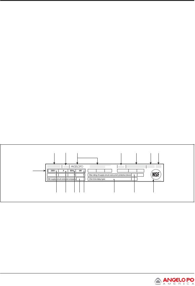
DATAPLATE LOCATION AND APPLIANCE SPECIFICATIONS
The dataplate, shown below, can be found attached to the appliance. It contains references and all essential information for operating safety.
A – Appliance model
B – Type of customization
C – Manufacturer identification E – Year of manufacture
F – Serial number G – Protection rating
H – Country of destination L – Voltage (V)
M – Amperage (A)
N – Frequency (Hz) P – Rated power (kW)
Q – Test voltage indicator
R– Certification marks
S– Min supply-circuit conductor current carrying capacity (current rating)
T– Max rating of supply-circuit overcurrent protective device
U– Type of supply-circuit overcurrent-protective device
A B C E F G H
Q
L M N S P U T R
PROCEDURE FOR REQUESTING SERVICE
Contact one of the authorized service centers for all requirements.
When requesting service, provide all information on the dataplate and a description of the problem.
14 Combination Oven Installation and Operation Manual

|
|
Section 3 |
|
|
Technical Specifications |
|
|
|
MODEL FX61-101 TECHNICAL SPECIFICATIONS |
|
|
|
|
|
Description |
FX 61 E3 |
FX 101 E3 |
Oven dimensions |
36.25 × 30.57 × (24.82 + 4 ) |
36.25 × 30.57 × (24.82 + 4 ) |
Electrical supply |
208V 3Ph 60 Hz |
208V 3Ph 60 Hz |
|
240V 3Ph Hz |
240V 3Ph 60 Hz |
|
|
480V 3Ph 60 Hz |
Rated power |
9.4 kW (208V3) |
17.75 kW (280V3) |
|
10.4 kW (240V3) |
17.9 kW (240V3 - 480V3) |
Power supply wire gauge |
10 AWG |
8 AWG (208V3 - 240V3) |
|
|
10 AWG (480V3) |
Chamber opening dimensions |
17.34 × 17.73” |
17.34 × 27.38 |
Chamber dimensions |
25.41 × 25.61 × 20.09 |
25.41 × 25.61 × 29.75 |
Number of containers |
6 |
10 |
Container spacing |
2.77 |
2.6 |
Container dimensions |
12.81 × 20.88 × 2.56 |
12.81 × 20.88 × 2.56 |
Current rating |
26.1 A (208V3) |
49.3 A (208V3) |
|
25 A (240V3) |
43.1 A (240V3) |
|
|
21.6 A (480V3) |
Maximum sound output is no higher than 65 dB (A).
MODEL FX82-122 TECHNICAL SPECIFICATIONS
Description |
FX 82 E3T |
FX 122 E3T |
Oven dimensions |
46.4 × 38 × (30.7 + 4 ) |
46.4 × 38 × (40.9 + 4 ) |
Electrical supply |
208V 3Ph 60 Hz |
208V 3Ph 60 Hz |
|
240V 3Ph 60 Hz |
240V 3Ph 60 Hz |
|
480V 3Ph 60 Hz |
480V 3Ph 60 Hz |
Rated power |
20.0 kW (208V3) |
26.0 kW |
|
20.7 kW (240V3 - 480V3) |
|
Power supply wire gauge |
8 AWG (208V3 - 240V3) |
6 AWG (208V3) |
Chamber opening dimensions |
25.22 × 23.64 |
25.22 × 33.88 |
Chamber dimensions |
35.07 × 32.51 × 26.2 |
35.07 × 32.51 × 36.45 |
Number of containers |
8 |
12 |
Container spacing |
2.77 |
2.6 |
Container dimensions |
20.88 × 25.61 × 2.56 |
20.88 × 25.61 × 2.56 |
Current rating |
55.6 A (208V3) - 49.9 A (240V3) |
72.3 A (208V3) - 62.6 A (240V3) |
|
24.9 A (480V3) |
31.3 A (480V3) |
Maximum sound output is no higher than 65 dB (A).
Combination Oven Installation and Operation Manual 15

Section 3
Technical Specifications
MODEL FX82-122 TECHNICAL SPECIFICATIONS
Description |
FX 82 E3 |
FX 122 E3 |
Oven dimensions |
46.4 × 38 × (51.8 + 5.9 ) |
46.4 × 38 × (62 + 5.9 ) |
Electrical supply |
208V 3Ph 60 Hz |
208V 3Ph 60 Hz |
|
240V 3Ph 60 Hz |
240V 3Ph 60 Hz |
|
480V 3Ph 60 Hz |
480V 3Ph 60 Hz |
Rated power |
20.0 kW (208V3) |
26.0 kW |
|
20.7 kW (240V3 - 480V3) |
|
Power supply wire gauge |
8 AWG |
6 AWGz |
Chamber opening dimensions |
25.22 × 23.64 |
25.22 × 33.88 |
Chamber dimensions |
35.07 × 32.51 × 26.2 |
35.07 × 32.51 × 36.45 |
Number of containers |
8 |
12 |
Container spacing |
2.77 |
2.6 |
Container dimensions |
20.88 × 25.61 × 2.56 |
20.88 × 25.61 × 2.56 |
Current rating |
55.6 A (208V3) - 49.9 A (240V3) |
72.3 A (208V3) - 62.6 A (240V3) |
|
24.9 A (480V3) |
31.3 A (480V3) |
Maximum sound output is no higher than 65 dB (A).
MODEL FX201-202 TECHNICAL SPECIFICATIONS
Description |
FX 201 E3 |
FX 202 E3 |
Oven dimensions |
36.6 × 31.24 × 62.06 |
46.61 × 38.34 × 62.06 |
Electrical supply |
208V 3Ph 60 Hz |
208V 3Ph 60 Hz |
|
240V 3Ph 60 Hz |
240V 3Ph 60 Hz |
|
480V 3Ph 60 Hz |
480V 3Ph 60 Hz |
Rated power |
35.5 kW (208V3) |
52 kW |
|
35.8 kW (240V3 - 480V3) |
|
Power supply wire gauge |
4 AWG |
6 AWG |
Chamber opening dimensions |
17.34 × 54.96 |
17.34 × 54.96 |
Chamber dimensions |
25.22 × 25.61 × 57.29 |
35.07 × 32.51 × 57.52 |
Number of containers |
20 |
20 |
Container spacing |
2.6 |
2.6 |
Container dimensions |
12.81 × 20.88 × 1.58 |
12.81 × 20.88 × 1.58 |
Current rating |
98.7 A (208V3) - 86.2 A (240V3) |
144.5 A (208V3) - 125.2 A (240V3) |
|
43.1 A (480V3) |
62.6 A (480V3) |
|
|
|
Maximum sound output is no higher than 65 dB (A).
16 Combination Oven Installation and Operation Manual
Section 4
Handling and Installation
HANDLING AND INSTALLATION
RECOMMENDATIONS FOR HANDLING AND INSTALLATION
 IMPORTANT _________________________
When handling and installing the appliance comply with the information provided by the manufacturer directly on the packaging, on the appliance and in the instructions for use.
If necessary, the person authorized to perform these operations must develop a “safety plan” to protect the people directly involved.
PACKAGING AND UNPACKING
Packaging is designed to reduce space and as appropriate to the type of transport used.
To simplify transport, some components may be removed and suitably protected and packed for transport.
The packaging carries all information necessary for loading and unloading.
When unpacking, check that all components are provided in the correct quantities and undamaged.
Packaging material must be properly disposed of in accordance with all local recycling rules and regulations.
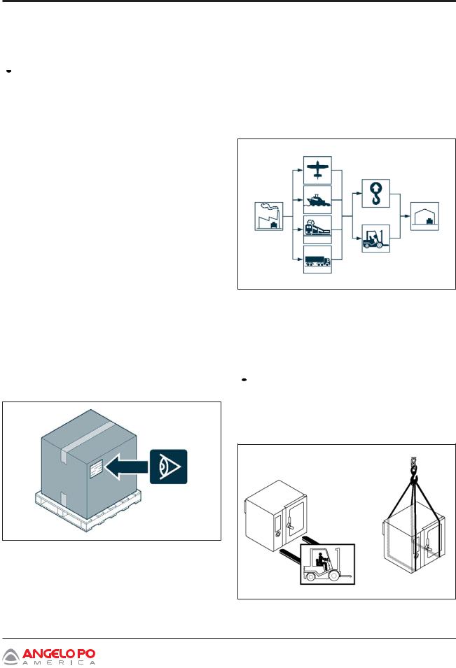
TRANSPORT
Different means of transport may be used, depending on the destination.
The chart below shows the most commonly used alternatives.
During transport, secure the package(s) properly to prevent unwanted shifting.
HANDLING AND LIFTING
The appliance can be handled using fork-lift or hook equipment of suitable load-carrying capacity. Before lifting, check the position of the load’s center of gravity.
 IMPORTANT _________________________
When engaging with the lifting equipment, note the location of all intake and outlet pipes.
Combination Oven Installation and Operation Manual 17
Section 4
Handling and Installation
APPLIANCE INSTALLATION
All installation stages must be considered based on the site survey and specific installation location of the unit. Before starting these stages, as well as deciding the place of installation, the person authorized to perform these operations must organize a “safety plan” to protect people directly involved, and must also ensure strict compliance with all legal requirements, especially those relating to mobile work-sites.
The location of the installation must have all the utility supply, ventilation, extraction and production residue venting connections required. In addition, the location must be suitably lit and meet all local health department and hygiene requirements to prevent the contamination of foods.
It is suggested to mark the location of each individual appliance or subassembly prior to installation.
Install in accordance with the relevant local codes, regulations and specifications in the country of use.
 IMPORTANT _________________________
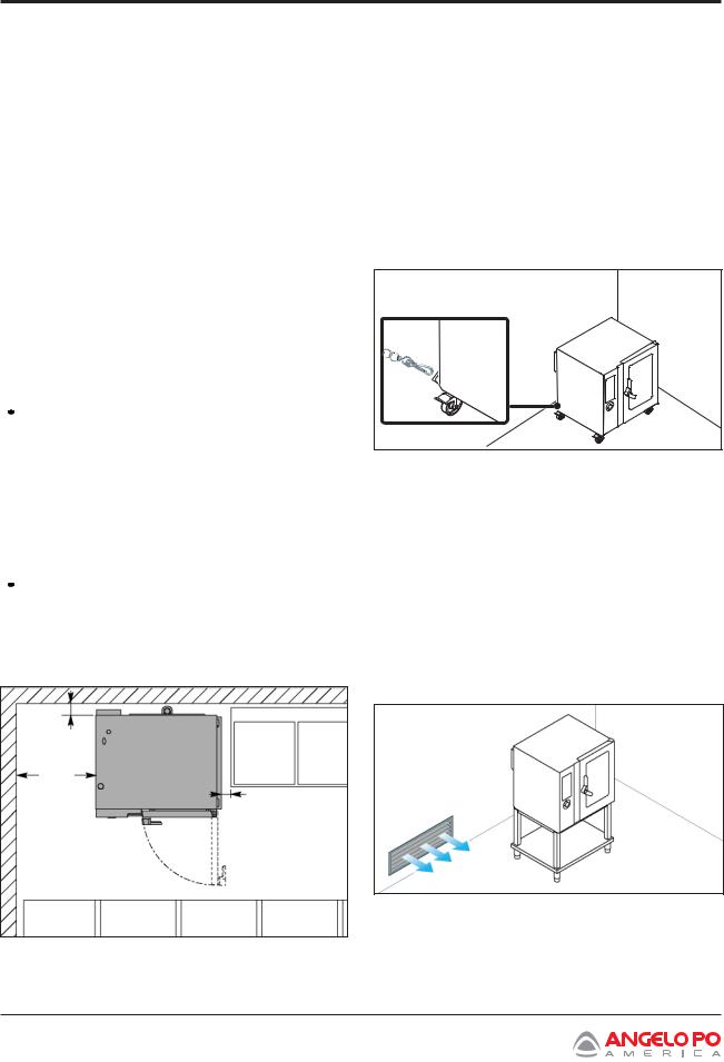
Install the appliance on a stand (available as an option) and position it as shown in the diagram (For version FX61-101-82-122 only).
If the oven is installed in the middle of a room, please leave at least a distance of 20 inches between its back and other appliances.
 IMPORTANT _________________________
All clearance requirements are the same for combustible or non-combustible constructions.
Suitable for installation on combustible floors.
3.94 in
20 in
3.94 in
CASTER - MOUNTED OVENS
For an appliance equipped with casters, the installation must be made with a connector that complies with the Standard for Connectors for Movable Gas Appliances, ANSI Z21.69 CSA 6.16, and a quick-disconnect device that complies with the Standard for Quick-Disconnect Devices for Use With Gas Fuel, ANSI Z21.41 CSA 6.9. Adequate means must be provided to limit the movement of the appliance without depending on the connector and the quick-disconnect device or its associated piping to limit appliance movement.
ROOM VENTILATION
The room where the appliance is installed must have air inlets to ensure that the appliance can operate correctly and provide the necessary air exchange in the room.
Air inlets must be of appropriate size, protected by gratings and placed so that they cannot be obstructed.
18 Combination Oven Installation and Operation Manual
Section 4
Handling and Installation
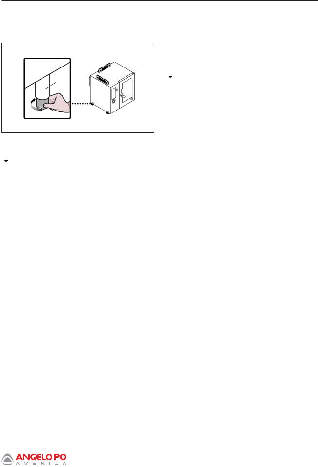
LEVELLING
Adjust the floor-mounted feet (A) to level the appliance.
A
WATER: REQUIREMENTS FOR SUPPLIED WATER CONNECTION
 IMPORTANT _________________________
The appliance must be supplied with drinking water having the characteristics shown in the table.
Description |
|
Value |
Pressure |
|
30 – 60 psi or |
|
|
200 - 400 kPa |
|
|
(2 - 4 bar) (*) |
Water flow rate (GPH) |
2.4 gph (FX 61) (*) |
|
|
|
3.2 gph (FX 101) (*) |
|
|
4.6 gph (FX 82) (*) |
|
|
4.6 gph (FX 122) (*) |
|
|
6.3 gph (FX 201) (*) |
|
|
8.5 gph (FX 202) (*) |
pH |
|
7 - 8.5 |
TDS |
|
40÷150 ppm |
Hardness |
|
3÷9°f (1,5÷5°d; |
|
|
2,1÷6,3°e; 30÷90 |
|
|
ppm) |
Langelier Index |
|
>0.5 |
(recommended) (**) |
|
|
Salt and metallic ion content |
|
|
|
|
|
Required |
Chlorine |
< 0.1 mg/l |
|
Chlorides |
< 30 mg/l |
|
Sulphates |
< 30 mg/l |
Recommended |
Iron |
< 0.1 mg/l |
(**) |
Copper |
< 0.05 mg/l |
|
||
|
Manganese |
< 0.05 mg/l |
|
|
|
(*) The value refers to the amount of water needed for steam production inside the cooking chamber.
(**)Different values of these parameters may cause corrosion if combined with wrong usage and environment.
 IMPORTANT _________________________
It is sole responsibility of the operator / purchaser / owner of this equipment to verify that the supply water, treated or not upstream of the water connection , falls within the standard values published in this document. Failure to comply with these values may damage the equipment and void the manufacturer’s warranty of the damaged parts.
Combination Oven Installation and Operation Manual 19
Section 4
Handling and Installation
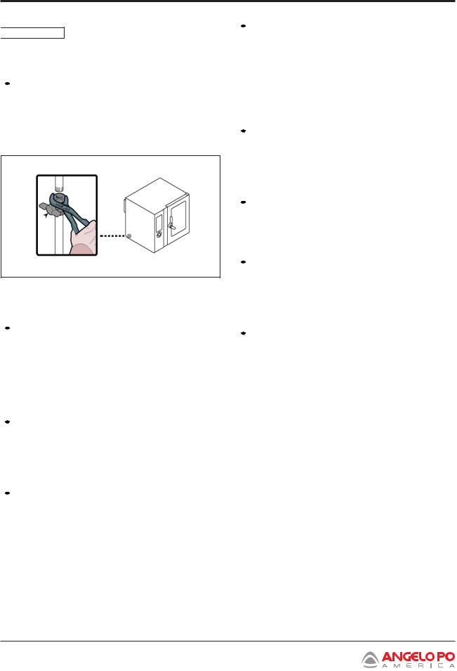
WATER CONNECTION

 WARNING Make the connection in compliance with the relevant legal requirements, using appropriate and recommended materials.
 IMPORTANT _________________________
This appliance is to be installed to comply with the applicable federal, state, or local plumbing codes having jurisdiction.
B 
WATER: RACCOMANDATIONS FOR USE  IMPORTANT _________________________
To maintain the hygienic features and integrity of the stainless steel over time (required for protection against corrosion), daily wash the cooking chamber (see page 82) with suitable detergents and completely dry it before use.
 IMPORTANT _________________________
Perform maintenance of the water treatment system (where it is installed) to ensure its proper functionality.
 IMPORTANT _________________________
Be sure to use new and fully functional accessories.
 IMPORTANT _________________________
Connect the mains line to the appliance’s connection pipe, fitting a shut-off tap (B) to allow the water supply to be cut off when necessary.
 IMPORTANT _________________________
Wherever chemicals are used in the water supply system for water sanification, for example chloramines or sodium hypochlorite, it is necessary to install a filter to guarantee their removal.
 IMPORTANT _________________________
Check water pipes and fittings for corroded parts, they may pollute the water inside the appliance.
 IMPORTANT _________________________
Use only detergents, chemicals and cleaning procedures suitable for the appliance.
 IMPORTANT _________________________
If the water features are such to require a treatment system, do not introduce untreated water inside the chamber during cooking. For example: if the type of cooking requires the presence of a pan full of water on the bottom pan tray, the water must have the features shown in the table on page 19.
If the water features are such to require a treatment system and the shower launching accessory is installed in the oven (LDR610 for models FX61-101-82- 122 and LDL only for models FX201-202), the water supplied by the latter must also be treated.
20 Combination Oven Installation and Operation Manual
Section 4
Handling and Installation
WATER DRAIN CONNECTION
To perform this operation, do the following.
1.Connect the water supply line pipe (A) to the appliance’s connection pipe (C).
2.Connect the vent pipe (D) to the appliance connection pipe (C) and attach it to the support (E).
3.94in
D
E
C
A
C
The appliance’s drain line is fitted with the plug
(B) to allow discharge of the any waste.
WASHING SUPPLY CONNECTION
To carry out this operation, proceed as follows:
1.Connect Jaune pipe (A) to pipe (B) and fit cone
(C)into the cleaner tank (D).
2.Connect Green pipe (E) to pipe (B) and fit cone
(C)into the sanitizing cleaner tank (F).
Use the cleaner and sanitizer supplied by the appliance manufacturer for the best results.
The chemical composition of the products referred to above is as follows:
Cleaner: caustic soda, concentration less than 20%.
Sanitizing cleaner: containing citrates and organic sequestering agents, less than 15%.
 IMPORTANT ________________________
B 
B 
A C

E
 F
F
D
The use of products with different compositions may damage the system and the oven walls, and any residues deposited may contaminate foods.
Combination Oven Installation and Operation Manual 21

Section 4
Handling and Installation
ELECTRICAL CONNECTION |
IMPORTANT _________________________ |
|
The appliance must be connected, grounded in accordance with all local codes, or in the absence of local codes, with the National Electrical Code, ANSI/ NFPA 70, or the Canadian Electrical Code, CSA C22.2.
 IMPORTANT _________________________
The connection must be made by authorized, skilled personnel, in accordance with the relevantlegalrequirements,usingappropriate and specified materials. The appliance is supplied with operating voltage 208V/3 or 240V/3 (available on request only for model FX61-101-82-122-201-202) or 480V/3 for FX202 (available on request only for model FX101-82-122) (see wiring diagrams).

 WARNING Before performing any service that involves electrical connection or disconnection and/or exposure to electrical components, always follow the Electrical LOCKOUT/TAGOUT Procedure. Disconnect all circuits. Failure to comply can cause property damage, injury or death.
 WARNING Before doing any work, cut off the main electricity supply.
Connect the appliance to the main power supply as follows.
1.Remove the screws and side panel (A).
2.Connect power input wires to the appliance’s terminal board (C), in accordance with the electrical system diagram provided at the back of the manual, using a cable with the following characteristics.
• Wire insulation temperature rating: ≥75°C (167°F).
Cooking chamber convection fan can rotate in a clockwise and counterclockwise direction.
TESTING THE APPLIANCE
 IMPORTANT _________________________
Before it is put into service, the system must be tested to check the operating conditions of every single component and identify any malfunctions. In this stage, it is important to check that all health and safety requirements have been complied with in full.
To test the system, make the following checks.
1.Turn on the water supply valve and make sure the connection is watertight.
2.Make sure main (input) voltage is the same as that of the appliance.
3.Check water pressure and adjust if necessary.
4.Check that the safety device is operating properly.
5.Perform a cooking cycle without food to ensure the appliance is operating properly.
After testing, train the user in all skills necessary to ensure safe operation of the appliance, in accordance with all legal requirements.
A
C
3.Replace side panel (A) and retighten all screws when the operation is complete.
22 Combination Oven Installation and Operation Manual
Section 4
Handling and Installation
ADJUSTMENTS
RECOMMENDATIONS FOR
ADJUSTMENTS
 IMPORTANT _________________________
Before making any type of adjustment, activate all the safety devices provided and decide whether staff at work and those in the vicinity should be informed. In particular, turn off the water supply tap, cut off the electricity supply using the master switch and prevent access to all devices that might cause unexpected health and safety hazards if turned on.

 WARNING Before performing any service that involves electrical connection or disconnection and/or exposure to electrical components, always follow the Electrical LOCKOUT/TAGOUT Procedure. Disconnect all circuits. Failure to comply can cause property damage, injury or death.
 WARNING Adjustments must be performed by an authorized service agent, in accordance with all relevant local and legal requirements.
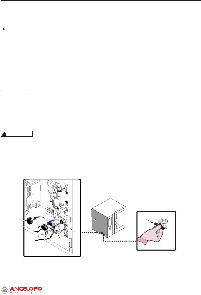
ADJUSTING THE WATER PRESSURE
To carry out this operation, proceed as follows:
1.Undo screws to remove side panel (A).
2.Turn on water supply valve (B).
3.Unscrew ring nut (C).
4.Use screw (D) (cleaning system water intake) to bring the pressure reading on pressure gauge
(E) to 22 psi (1.5 bar).
If the water pressure is too low, install a device to increase the pressure.
5.Retighten ring nut (C).
6.Unscrew ring nut (F).
7.Turn screw (G) (cooking chamber water intake) to bring pressure reading on pressure gauge (H) to 14.5 psi (1 bar).
If the water pressure is too low, install a device to increase the pressure.
8.Retighten ring nut (F).
9.Return panel (A) to it’s original position and replace screws.
10.Turn water supply valve (B) off when the operation is complete.
|
|
|
|
|
|
|
H |
|
|
F |
|
|
E |
|
|
|
A |
|
B |
|
|
|
|
||||||
|
|
|
|
|
|
|
|||
|
|
|
|
|
|
|
|
||
|
|
|
|||||||
C |
|
|
|
|
|
|
D |
|
|
|
|
|
|
|
|
|
|
||
|
|
|
|
|
|
|
|
|
|
|
|
|
|
|
G |
|
|
||
|
|
|
|
|
|
|
|
|
|
|
|
|
|
|
|
|
|
|
|
Combination Oven Installation and Operation Manual 23

Section 4
Handling and Installation
24 Combination Oven Installation and Operation Manual

Section 5
Operation
OPERATION
RECOMMENDATIONS FOR USE
 IMPORTANT _________________________
The rate of accidents resulting from the use of appliances depends on many factors which cannot always be predicted and controlled. Some accidents may be caused by unpredictable environmental factors, while others are caused by misuse or abuse. Being familiar with the appliance and the normal operating modes will help reduce the occurrence of accidents or errors.
Use only as intended by the manufacturer and do not tamper with any devices to obtain operations other than those intended.
Before each use, make sure all safety devices are fully installed and functional.
In addition to complying with the above requirements, users must apply all safety regulations and read the description of the controls and the start-up instructions carefully.
Immediately report any irregularities observedordeteriorationofthecomponents or parts of the appliance. If necessary, ask for help from a more experienced user or call an authorized service agent for additional help.
DESCRIPTION OF CONTROLS
The illustration shows the appliance’s control panels, while the list details the descriptions and functions of the individual controls.
A.Digital display: displays the selected mode of operation and alarm codes.
B.Function enabling button: enables the function shown on the display.
C.Back button: cancels the current operation and returns to the previous page.
D.Reset button: resets the alarms (beepers and lights).
F. Knob: Used to select the function required or modify values. To select one of the zones required (function or value) turn the knob clockwise or counter-clockwise
•Clockwise: scrolls “downwards” through zones or increases the value shown.
•Counter-clockwise: scrolls “upwards” through zones or decreases the value shown.
After selecting the function required or the value, press the knob to confirm and save the function or value.
G.On/off button: turns the appliance’s electricity supply on and off (I=ON; O=OFF).
H.USB port: used to connect a remote data storage unit to the appliance.
L.HELP button: gives information on the function that is being used.
|
|
|
|
|
|
|
|
|
|
|
A |
|
|
|
|
|
|
|
|
|
|
|
|
|
|
|
|
|
|
|
|
|
|
|
|
|
|
|
|
|
|
|
|
|
|
|
|
|
|
|
|
|
|
B |
|
|
|
|
|
|
|
|
|
|
|
|
|
|
|
|
|
|
|
|
|
|
|
|
|
|
|
|
|
|
|
|
L |
C |
|
|
|
|
|
|
|
|||
|
|
|
|
|
|
|
|
|||
|
|
|
|
|
|
|
|
|
|
|
|
|
|
|
|
|
|
|
|
|
|
D |
|
|
|
|
|
|
|
|
E |
|
|
|
|
|
|
|
|
||||
F
H G
E.“START-STOP” button: starts or ends the selected program cycle, shown on the display (cooking cycle, washing cycle, etc.).
Combination Oven Installation and Operation Manual 25
Section 5
Operation
SWITCHING THE APPLIANCE
ON AND OFF
Proceed as follows:
Lighting
1.Operate the appliance’s master switch to connect it to the electrical power supply.
2.Turn on water supply valve.
3.Press button (G) to turn on the appliance.
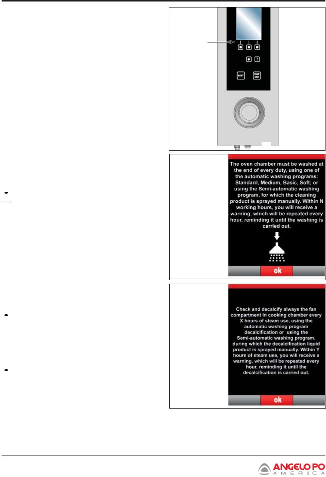
4. Display (A) comes on, after a few seconds it shows the page. >>>
5. Press OK to reset and go to the next page.
 IMPORTANT
The N value of the hours is the residual cooking time between one wash and the next (max.12 h - min. 1h).
A
 G
G
The display will show page. |
>>> |
6.Press OK to go to the main functions of the appliance.
 IMPORTANT
The Y value of the hours is the residual water introduction time in the chamber during a cooking process available between one descaling and the next (max 15h - min 1h).
Turning off
 IMPORTANT
Always switch off the appliance after use.
7.Press button (G) to switch off the appliance.
8.Turn off water supply valve.
9.Cut off main electrical supply using the appliance’s master switch.
26 Combination Oven Installation and Operation Manual
Section 5
Operation
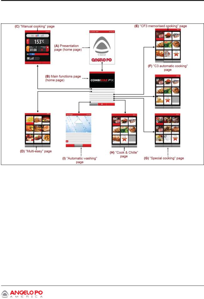
MENU STRUCTURE CHART
The chart shows the various display pages covering the various operating modes.
A.Presentation page: displayed when the appliance is switched on.
B.Main functions page (home page): used to access the pages for programming and display of the appliance’s operating parameters (see page 27).
C.Manual cooking” page: used to enter the data (temperature, cooking time, etc.) to allow cooking to be performed in “manual mode” (see page 38).
D.“Multi-easy” page: this is used to activate the function for the simultaneous managementof the stored cooking processes (see page 55).
E.“CF3 memorized cooking” page: used to select, amend or create cooking programs (see page 48).
F.“C3 automatic cooking” page: used to recall the cooking modes pre-set for the different foods (see page 45).
G. “Special cooking” page: used to recall the particular cooking mode (e.g. Smoking, pasteurization, holding, BT cooking, dry, delta T, vacuum, regeneration, favorites) (see page 54)
H.“Cook & Chill” page: this is used to manage cooking programs associated with the blast chiller (see page 63).
I.“Automatic washing” page: used to select the type of program for cleaning of the appliance (see page 65).
L.“Settings” page: used to set the functioning parameters of the appliance (see page 32).
M.“Service” page: function for the exclusive use of an authorized technician (to be used with Password).
N.”HACCP” page: used to display the HACCP
data acquired during different cooking (see page 72).
N.”Data load/download” page: used to load the oven with new cooking programs or to download the cooking programs from the oven on to an external memory unit (USB Memory) (see page 73).
Combination Oven Installation and Operation Manual 27
Section 5
Operation
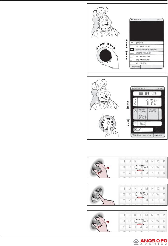
HOW TO ACCESS THE MENU PAGES
Proceed as follows.
1.Select function required (submenu) using the knob.
2.Press knob to confirm selection.
3.Select operating setting value to be modified using the knob.
4.Press knob to confirm selected value.
5.Modify the value of the selected setting using the knob.
6.Press knob to confirm the new value displayed.
HOW TO ENTER ALPHANUMERICAL VALUES
Proceed as follows:
1. Use the knob to select the first character (letter or number) required. >>>
2.Press knob to confirm highlighted selection.>>>
3.Select the second character (letter or number)
required using the knob. |
>>> |
28 Combination Oven Installation and Operation Manual
Section 5
Operation
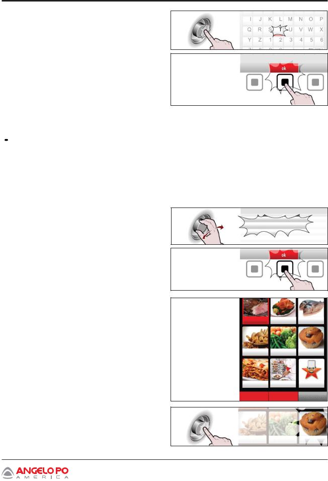
4. Press the knob to confirm the highlighted selection. >>>
5.Repeat these steps until the entire value for the setting is displayed.
6.Press the button to confirm the value or
description selected. |
>>> |
ELIMINATING/RESTORING TYPES OF
FOOD
 IMPORTANT _________________________
This function can be used for the following modes: Multi-easy, CF3 Saved cooking programs, C3 Automatic cooking programs, Special cooking programs and Cook&Chill.
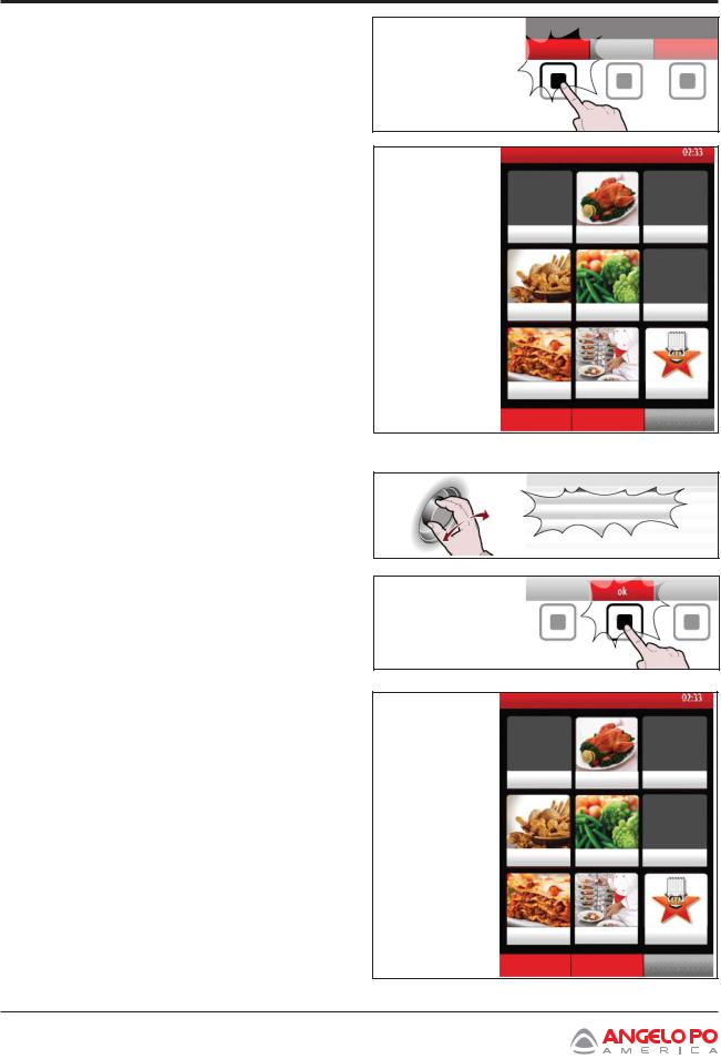
Removing food
Proceed as follows:
1. |
Select the “CF3 memorised cooking” function |
|
|
using the knob. |
>>> |
2. |
Press the button to confirm the value or |
|
|
description selected. |
>>> |
The display will show page. |
>>> |
The page is used to select the type of foods to remove.
3. Use the knob to select the type of food. |
>>> |
CF3 memorised cooking
meat |
poultry |
fish |
bread |
vegetables confectionery |
pasta banqueting favorites regeneration
delete restores
confectionery
Combination Oven Installation and Operation Manual 29
Section 5
Operation
4. Press the button to eliminate the type of food.
>>>
The types of food not eliminated will appear on the display. >>>
delete
poultry
bread vegetables
pasta banqueting favorites regeneration
delete restores
Reintroducing food |
|
|
Proceed as follows: |
|
|
1. |
Select the “CF3 memorised cooking” function |
|
|
using the knob. |
>>> |
2. |
Press the button to confirm the selected |
|
|
function. |
>>> |
CF3 memorised cooking
The display will show page. |
>>> |
poultry
bread vegetables
pasta banqueting favorites regeneration
delete restores
30 Combination Oven Installation and Operation Manual
 Loading...