

Page 1
Controlling Tomorrow’s World
TCX 865 VAV Controller
Family
Downloaded from - http://www.guardianalarms.net
Installation Guide
TCX 865
30-3001-497 Version D
Page 2

Page 3

Version D
Reproduction or distribution forbi dden.
Copyright 1997 by Andover Controls.
Subject to change without notice.
Order No. 30-3001-497
Copyright
1997
Andover Controls Corporation
300 Brickstone Square
Andover, Massachusetts 01810 USA
All Rights Reserved.
Published by the Engineering Department at Andover Controls Corporation.
IMPORTANT NOTICE
This product is subject to change without notice. This document does not constitute any
warranty, express or implied. Andover Controls Corporation reserves the right to alter capabilities, performance, and presentation of this product at any time.
TCX 865 Installation Guide
i
Page 4

Note
This equipment has been tested and found to comply with the limits for a Class
A digital device, pursuant to Part 15 of the FCC Rules. These limits are
designed to provide reasonable protection against harmful interference when
the equipment is operated in a commercial environment. This equipment
generates, uses, and can radiate radio frequency energy and, if not installed
and used in accordance with the instructions in this manual, may cause
harmful interference to radio communications. Operation of this equipment
in a residential area is likely to cause harmful interference in which case the
user will be required to correct the interference at his own expense.
Note
This digital apparatus does not exceed the Class A limits for radio noise
emissions from digital apparatus set out in the Radio Interference Regulations
of the Canadian Department of Communications.
Avis
Le présent appareil numérique n’émet pas de bruits radioélectriques dépassant
les limites applicables aux appareils numériques de la class A prescrites dans
le Règlement sur le brouillage radioélectrique édicté par le ministère des
Communications du Canada.
ii
Andover Controls Corpor ati on
Page 5

Contents
TCX 865 Series VAV Controller
TCX 86X Series Characteristics ........................................................................................2
What You Received ...........................................................................................................2
Parts Included with the TCX 86X Series .....................................................................2
Mechanical Installation ......................................................................................................3
Chassis Road Map .............................................................................................................5
Power Connection ..............................................................................................................6
Battery Connection & Replacement .................................. .......... .......... .......... .......... ..6
24 VAC Connection .....................................................................................................7
Building Ground Requirements ...................................................................................8
Inspecting the Ground ..................................................................................................8
Lightning Protection ....................................................................................................8
Infinet Network Connection ..............................................................................................9
Input Connections ................................................... .......... .......... .......... .......... .......... .......10
Universal Inputs .........................................................................................................10
Input Wiring ...............................................................................................................10
Wiring Concerns ........................................................................................................11
Thermistor Inputs .......................................................................................................11
Voltage Inputs ............................................................................................................14
Digital/Counter Inputs ...............................................................................................14
Air Flow Sensor Connection ............................................................................................15
Output Connections .........................................................................................................16
Output Wiring ............................................................................................................16
TCX 866 Analog Output Wiring ................................................................................16
Switching Loads with Triacs ......................................................................................17
Form A Outputs .........................................................................................................17
Form K Tri-state Outputs ...........................................................................................17
Analog Outputs...........................................................................................................18
Operation .........................................................................................................................19
TCX 865 Installation Guide
iii
Page 6

Service Tool ...............................................................................................................20
Pre-Operation Checks ..........................................................................................20
Initial Power-Up .......................................... ... .. ...... .... ...... .... ...... .... ...... .... ...... .... .20
Troubleshooting ...............................................................................................................21
CPU LED Is Not Blinking ...................................................................................21
Unit Appears Functional But Is Not Responding To CX Controller ...................21
One Input or Output Appears to Be Dysfunctional .............................................22
Internal Reset Switch............................................................................................22
Sample Applications ........................................................................................................23
iv
Andover Controls Corporation
Page 7
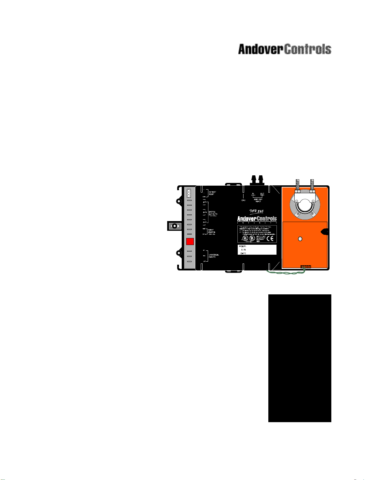
TCX 865
V AV Controller
This manual describes the installation and care of the TCX 865 Series VAV control
units.
The Infinity TCX 865 Series VAV controllers are unique VAV box controllers that come
equipped with a built-in damper actuator to streamline hardware installation.
The TCX 865 series features several combinations of universal inputs, an on-board
pressure transducer, Form A, and Tri-state outputs for flexible control configurations.
Metal oxide varistors and optocouplers provide 2500V isolation on each triac-based
output on theTCX 865 models to ensure noise-free operation and virtually elimina te
the need to install MOVs in the field.
Infinity
The Infinet’s true peer-to-peer communications protocol provides the
Infinity
with the ability to instantly communicate with an
CX 9200, as well as the entire network of Andover Infinet field controllers. Up to 254
TCX 865 series controllers can be networked to one CX series network controller.
network controller such as the
TCX 865
TCX 865 F amily Insta llatio n Gu id e
1
Page 8

TCX 865 Series Characteristics
The following table lists the features included in the TCX 865:
Model Outputs Inputs Special
TCX 865 3 Form A Triac outputs 2 Universal Inputs Damper Actuator
or 1Form K Tri-state output Airflow sensor (0-1” W.C.) RTC*
and 1 Form A Triac output
TCX 866 3 Form A Triac outputs 3 Universal Inputs Damper Actuator
or 1Form K Tri-state output Smart Sens or Input RTC*
and 1 Form A Triac output
2 Analog outputs Airflow sensor (0-1” W.C .)
* RTC: Hardware-based, battery-maintained real time clock.
What You Received
After unpacking the unit, take care to not damage the packaging material—you must reuse it if
you ship the product back for repair.
Parts Included with the TCX 865 Series
TCX 86X Controller
5-micron Ramay Filter
Hardware Reference Manual (this document)
2
Andover Controls Corpor ati on
Page 9
Mechanical Installation
The TCX 865 Series is designed to be mounted directly to the shaft of an air handler. The
shaft is inserted through the opening in the controller and secured using a U-bolt.
Note:
The unit requires that the VAV blade shaft be at least 1.5” (38 mm) in length and 1/4”-5/8” (616 mm) in diameter (1/4” - 7/16” (6-11 mm) square) for proper mounting.The unit may be
mounted in any orientation.
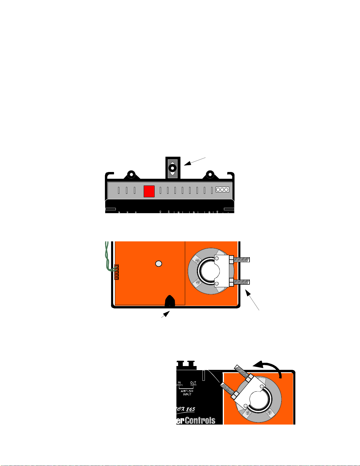
Attach the TCX 86X to the air handling unit using the procedure outlined below:
1. Center the movable grommet in its mounting trough as illustrated:
Center the Grommet
2. Loosen the nuts that attach the mounting U-bolt to the actuator motor.
Manual override button
3. Manually, position the damper blade at its fully closed position.
4. With the manual override button depressed, rotate the actuator clamp of the TCX 86X
motor counter clockwise to approximately 1/16 - 1/8” between the actuator stop and
clamp, depending on seal design.
U-b olt clamp wit h nu t s
TCX 865 F amily Insta llatio n Gu id e
3
Page 10
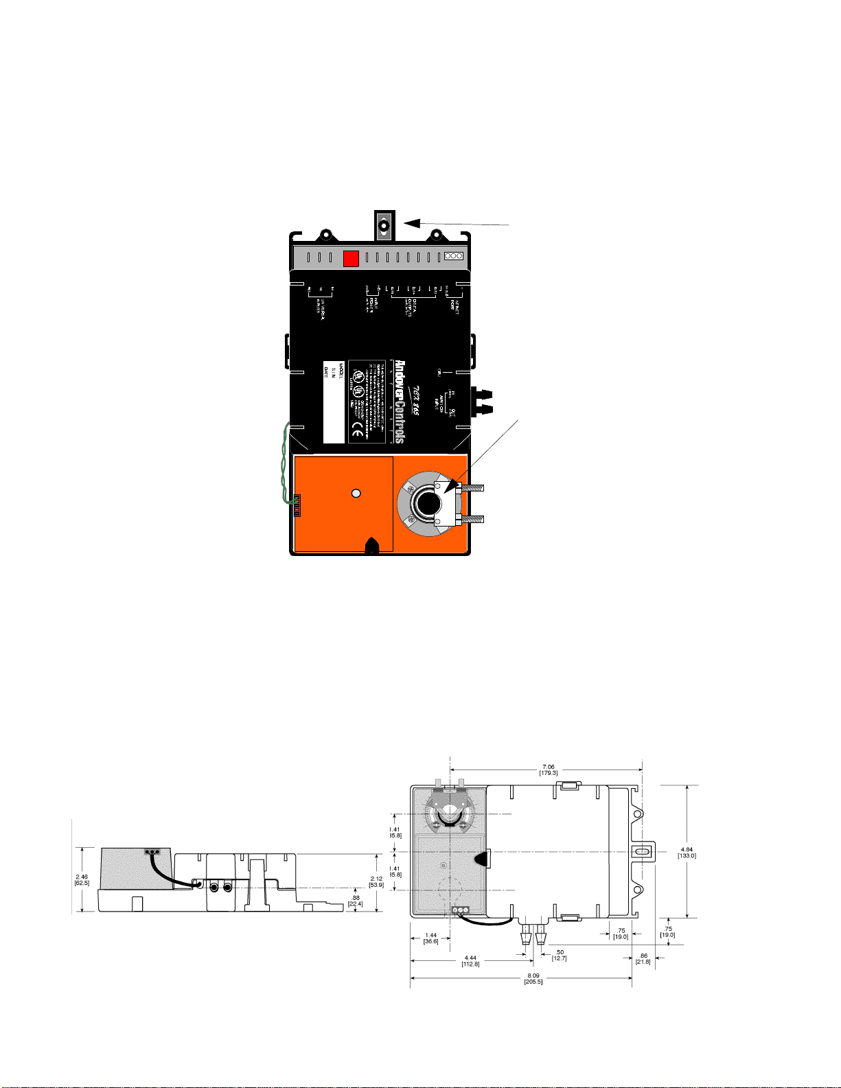
5. Position the unit at the proper perspective on the VAV box. Carefully insert the shaft of the
VAV unit into the opening of the actuator motor through the U-bolt. Make sure the TCX 86X
is flush with the VAV housing. Finger tighten the nuts to secure the shaft to the actuator.
6. Insert the supplied self-tapping screw through the grommet and secure the TCX 86X to the
housing.
Self-tapping screw
secures the unit to
the housing
Shaft inserted into
the actuator.
7. Tighten the U-Bolt to the shaft using an 8 mm wrench.
Overall Dimensions
The TCX 865 Series are designed to fit over an existing VAV shaft and be mounted to the housing. It is secured via one sheet metal screw. The overall dimensions of the unit are:
4
Andover Controls Corpor ati on
Page 11

Chassis Road Map
The following diagr am indicates the locations of each of the main components and connection
points:
Digital
Outputs
24VAC
Power
Damper
Reset
Button
Infinet Connection
CPU
LED
Airflow Sensor
Damper
Actuator
Universal
Inputs
AnalogOutputs
& Other Inputs
(under removable cover)
TCX 865 F amily Insta llatio n Gu id e
5
Page 12

Power Connections
Power Connection
The TCX 865 Series Controllers are operated via an individual external 24 Volt AC source. An
internal power converter creates the necessary DC voltages to supply the microprocessor circuitry.
Should the AC source be interrupted during operation, backup power for the internal controller
state memory is provided by a coin-style 3 Volt Lithium battery. This battery can maintain
backup status for typically 3-years.
Battery Connection & Replacement
To access the battery holder, the main electronics housing cover must be removed. The cover
is secured via two force fitting plastic clamps. To remove the cover gently pry the two clamps
outward using your thumbs while lifting the cover.
Once the cover is removed the printed circuit board is accessible. The following illustrates the
location of the battery in relation to the board.
Battery is locat ed
here.
During shipment, an insulating plastic tab is inserted under the clip on the battery to prevent it
from draining prior to installation. To activate the battery, this tab must be removed.
Should it become necessary to replace the battery, The battery is placed in a coin-style holder.
The battery used in the TCX865 Series are a type CR 1225, 38 mAhr 3.0 V primary Lithium
battery.
CAUTION
There is danger of explosion if the battery is incorrectly replaced.
Replace only with the same or equivalent type recommended above.
Dispose of used batteries according to manufacturer’s instructions.
Andover Controls Corpor ati on
6
Page 13

Power Connections
24 VAC Connection
The TCX 865 Series controllers are powered by an external 24 VAC source . This power supply
is connected via three terminals located near the center of the I/O connection area. The unit
should receive power from its own independent, 24 VAC +10% /– 15%, 50 or 60 Hz, 10 VA ,
unswitched circuit.
OUT 4
OUT 5
24VAC
GND
24 VAC Step-Down
Transform er
AC Line
Power
choose a voltage rating appropriate to the
input voltage applied. i.e 130V or 250V
Optional Varistor
Optional 39V Varistor
for extremely noisy environments
X1
X2
Black
White or
Green
The 24 VAC connection consists of both terminals from the secondar y of a power-line to 24
VAC transformer and a common ground line. Connection to the Controller is through push-on
quick-disconnect type connectors. The ground wire should not exceed 12” in length and it
must be connected to a good earth ground.
Warning
Make sure that 24 VAC is
the controller, or you could receive an electrical shock that is life-threatening.
connected to the power cable while you are wiring
not
TCX 865 F amily Insta llatio n Gu id e
7
Page 14

Power Connections
Building Ground Requirements
Be sure that all equipment from Andover Controls is grounded to true Earth ground. True
Earth ground protects the equipment from transients and other power surges in the area. We
cannot guarante e that the contro l ler system will operate as documented wit hout a proper ly
grounded installation.
An example of a sub-standard ground is a galvanized steel cold water pipe. As the pipe corrodes, it does not act as a true ground. The corrosion acts as an insulator, raising the potential
of the pipe with respect to the ground.
When lightning strikes in the area of the installation, it drastically changes the potential of the
Earth. Since properly grounded Andover Controls units respond to changes in potential more
rapidly than poorly grounded electrical systems, a poorly grounded building tries to reach
ground through the Andover Controls system. The surge of current can destroy electronic
components on the controller board. Surges of much lower potential than lightning also impact
the reliability of the equipment.
Inspecting the Ground
Be sure to have your grounds inspected before you begin the installation process to be sure
your municipality follows the National Electrical Code.
code and often have substandard electrical grounds.
Check your ground as follows:
Inspect the building power distribution panel for Earth-ground termination. If the ground termi-
nation is any of the following, it is not adequate and must be corrected:
• Does not exist.
• Is connected to a corroded or galvanized pipe.
• Is connected using a small gauge wire (less than 14 AWG).
Be sure your Andover Controls cabinet is connected to the ground with a copper conductor
that terminates at the distribution panel.
Many municipalities do not follow the
Lightning Protection
Although metal oxide varistors are built into the board to protect against power line transients,
this protection is not sufficient to protect against lightning. Lightning arresters are required at
Infinet
each point where
ommended:
Andover Controls # 01-2100-299, Tw o pair gas tube lightning arrester
cables enter or exit a building. The following lightning arrester is rec-
Andover Controls Corpor ati on
8
Page 15

Infinet Connections
Infinet Network Connection
The TCX 865 Series controllers include an interface to the Andover Controls proprietary Infinet
network. Connection to the Infinet allows multiple controllers to communicate and be controlled by a larger “host” controller.
Connection to the Infinet requires access to an Infinet network cable. This cable consists of
two wires and a shield. A screw-type terminal block Infinet connector is provided on the printed
circuit board.
Connect the Infinet
Here.
To wire the Controller to the Infinet, follow the steps below:
8. Trim the outer jacket of the Infinet cable to reveal the internal wires.
9. Strip the insulation from the white* wire and loosen the screw labeled ‘+’
10. Insert the stripped end of the white* wire into the ’+’ receptacle of the terminal block.
Tighten t he screw.
11. Strip the insulation from the black* wire and loosen the screw labeled ‘-’
12. Insert the stripped end of the black* wire into the ’-’ receptacle of the terminal block.
Tighten t he screw.
13. Insert the shield wire into the ‘SHIELD’ receptacle of the terminal block. Tighten the screw .
* Wire colors are included for clarity. The colors of your cable may vary . However, make sure that all Infinet connections are consistent on their connections.
White
Black
+ -
Infinet Cables.
White
SHLD
Shield
OUT 3
TCX 865 F amily Insta llatio n Gu id e
9
Page 16

Input Connections
Input Connections
Universal Inputs
The TCX 865 Series controllers include Andover Controls Universal Inputs that are unique in
that they are software configurable to handle any one of a number of input types:
Thermistor
Voltage
Digital/Counter
Input Wir i ng
The actual input terminations are located as shown. Connection is via a 0.250” (6.35 mm)
male spade lug.
Connect Inputs
1 and 2 Here
IN1 IN2
RET
The inputs labeled IN1,and IN2 are followed by a connection labeled RET for the input signal
return. Although there is only one return terminal (RET) supplied, it is recommended that a
separate return wire be used for each input. All return wires should be crimped into one female
spade lug for connection to the RET terminal.
TCX 866 Inputs labeled IN3,and IN4 are found on the screw terminal strip at the top right of
the daughter board mounted over the main PC board under the removable plastic cover. To
remove the cover, simply pull outward on the two opposite tabs that lock the cover to the base
and pull upward. IN3 is used for the Smart Sensor only. For more information regarding the
Smart Sensor, refer to its installation manual. IN4 is f ollow ed by a connection labeled RET for
the input signal return. A separate shield may be connected to the SHLD terminal.
Andover Controls Corporation
10
TCX 866 Extra Input Connections
IN3
IN4
RET
SHLD
Page 17

Input Connections
Wiring Concern s
Do not remotely ground any part of the sensor wiring. Remote grounds connected to the TCX
865 Series return terminal could make the controller operate incorrectly or damage the equipment. The signal return is not true earth ground. It is an electronic reference point necessary
to interpret the sensor properly.
It is recommended that you run input wiring in a conduit separate from AC power or output wiring and avoid long wiring runs.
For reliable input operation, follow these input wiring guidelines:
• Never lay wires across the surface of the printed circuit board.
• Wires should never be within 1 in. or 25 mm of any component on the printed circuit board.
• Use shielded input wire.
• Terminate the shield of the input wires at one end of the run only—preferably at the end
where your controller is located.
• Be careful when stripping wire not to drop small pieces of wire inside the cabinet.
• Don’t run your input wiring in the same conduit with AC power.
• Don’t run your input wiring in the same conduit with your output wiring.
Caution
Do not externally ground any input connected to the Controller. This may damage
the unit. Signal return terminals are not connected to Ear t h Ground.
Thermistor Inputs
The TCX 865 Series inputs may be configured to sense temperature by connecting a resistive
thermistor to any one of the input terminals. The following is a schematic representation of the
connection:
One lead connects to the numbered input terminal, the other to a return terminal.
INx
Thermistor
RET (return)
Caution
Never apply a voltage to a thermistor—doing so alters the thermistor’s accuracy
and reliability. In fact, it’s a good idea to replace any thermistor that has had any
sort of voltage applied to it.
TCX 865 Family Installation Guide
11
Page 18

Input Connections
Special Factors for Thermistors
To keep thermistor errors minimal, limit the length of wire runs to the maximum for the gauge
wire you select.
The following three tables indicate the maximum length runs for wires of various gauges to
keep errors within certain temperature limits when using thermistor elements.
Gauge
#14
2.5 mm
2
#16
1.5 mm
2
#18
1.0 mm
2
#20
0.5 mm
2
#22
0.35 mm
Wire Gauges and Corresponding Maximum Runs for Sensing Temperatures Up to
70
F (21°C)
°
Gauge
#14
2.5 mm
2
1
/
° F (.28 ° C) Error
2
26,700 ft
8150 m
16,700 ft
5120 m
10,500 ft
3200 m
6,600 ft
2000 m
4,100 ft
2
1250 m
1
/
° F (.28° C) Error
2
12,600 ft
3800 m
1
/
° F (.14 ° C) Error
4
13,300 ft
4000 m
8,300 ft
2500 m
5,200 ft
1600 m
3,300 ft
1000 m
2,000 ft
600 m
1
/
° F (.14° C) Error
4
6,300 ft
1900 m
1
/
° F (.06° C) Error
10
5,300 ft
1600 m
3,300 ft
1000 m
2,100 ft
640 m
1,300 ft
400 m
800 ft
250 m
1
/
° F (.06° C) Error
10
2,500 ft
760 m
#16
1.5 mm
2
#18
1.0 mm
2
#20
0.5 mm
2
#22
0.35 mm
Wire Gauges and Corresponding Maximum Runs for Sensing Temperatures Up to
F (38°C)
100
°
Andover Controls Corporation
12
7,900 ft
2400 m
5,000 ft
1500 m
3,100 ft
950 m
1,900 ft
2
580 m
3,900 ft
1200 m
2,500 ft
760 m
1,500 ft
450 m
900 ft
275 m
1,500 ft
450 m
1,000 ft
300 m
600 ft
180 m
300 ft
90 m
Page 19

Input Connections
Gauge
#14
2.5 mm
2
#16
1.5 mm
2
#18
1.0 mm
2
#20
0.5 mm
2
#22
0.35 mm
Wire Gauges and Corresponding Maximum Runs for Sensing Temperatures Up to
150
°
F (65°C)
1
/
° F (.28 ° C) Error
2
4,100 ft
1250 m
2,600 ft
800 m
1,600 ft
500 m
1,000 ft
300 m
600 ft
2
180 m
Thermistor Input Specifications
Range
–30 to 230 °F
(–34 to 110 °C)
Accuracy
(Using an Andover Controls Thermistor)
+/– 1 °F over a 10 °F to 150 °F range
+/– 0.55 °C over a –23.3 to 65.5 °C range
1
/
° F (.14 ° C) Error
4
2,000 ft
600 m
1,300 ft
400 m
800 ft
240 m
500 ft
150 m
300 ft
90 m
1
/
° F (.06° C) Error
10
800 ft
240 m
500 ft
150 m
300 ft
90 m
200 ft
60 m
100 ft
30 m
TCX 865 Family Installation Guide
13
Page 20

Input Connections
Voltage Inputs
The TCX 865 Series inputs may be configured to sense voltage by connecting the input terminals to a voltage source. The following is a schematic representation of the connection:
One lead connects to the numbered input terminal, the other to a return terminal.
INx
+
V
-
RET (return)
Voltage Input Specifications
Vo lta ge Range
Resolution
Accuracy
Input Impedance
Filtering
Calibration
0 to 5.115 V
0.005 V
+/–0.015 V
10KΩ referenced to 5.120 V
Corner Frequency at 15 Hz, –20 db/decade
Permanent (factory)
Digital/Counter Inputs
The TCX 865 Series inputs may be configured to sense a contact closure by connecting the
input terminals to a digital or counter input source. The followi ng is a schematic representation
of the connection:
One lead connects to the numbered input terminal, the other to a return terminal.
INx
RET (return)
Digital/Counter Input Specifications
Inpu t Type
Maxi mum Pulse Freque ncy
Pulse Width
Andover Controls Corporation
14
Contact Closure
4 Hz at a duty cycle of 50%
125 ms minimum
Page 21

Air Flow Sensor C on ne ct i on s
Air Flow Sensor Connection
All models of the TCX 865 Series controllers include an airflow sensor.
The air flow sensor is located at the top of the controller chassis:
Filter
IN
(HIGH)
CPU
Side marked
‘IN’ Here
AIRFLOW
INPUT
The following steps explain the connection of the air flow sensor:
OUT
(LOW)
1. Using a small piece of 1/4” (6.35 mm) I.D. pneumatic tubing, attach the ‘OUT’ side of a 5
micron filter to the input connection (the side marked ‘IN’) of the sensor as shown above.
2. Connect a 1/4” I.D. pneumatic tube from the other end of the filter (the side marked ‘IN’) to
the ‘HI’ opening on a VAV box.
3. Connect a 1/4” I.D. pneumatic tube from the output connector (the side marked ‘OUT’) of
the air flow sensor to the ‘LO’ opening on a VAV box.
Note: Keep tubing to a maxi mum of 15 in ches (380.99 mm) in length.
Air Flow Input Specifications
Range
Resolution
Accuracy
0 to 1” WC (0-249 Pa)
0.005” WC (1.25 Pa) @ 73 °F (23 °C) @ Standard Air Conditions
+/– 0.05” WC (12.5 Pa) @ 73 °F (23 °C) @ Standard Air Conditions
TCX 865 Family Installation Guide
15
Page 22

Output Connections
Output Connections
The TCX 865 Series controllers include 3 Form A Triacs that can be used separately or be
configured into 1 Form K Tr i-s tate output with a free triac output remaining.
TCX 866 controllers include 2 analog outputs.
Output Wiring
Triac output terminations are located along the left side of the chassis. Connection is via a
0.250” (6.35 mm) male spade lug.
Connect Triac
Outputs Here
TCX 866 analog output termination s are found on the screw terminal strip at the top right of
the daughter board mounted over the main PC board under the removable plastic cover. To
remove the cover, simply pull outward on the two opposite tabs that lock the cover to the base
and pull upward. Corresponding signal returns labeled RET are provided to either
side of the output terminals. A separate shield input is provided as well.
TCX 866 Analog Output Connections
RET
OUT6
OUT7
RET
SHLD
Andover Controls Corporation
16
Page 23

Output Connections
Switching Loads with Triacs
Although the Triac-based outputs provided with this unit appear as relay contacts in the schematics provided, they are actually solid-state switches that have limitations on the loads they
can switch.
AC vs. DC
The first limitation is that they cannot be used with DC loads.
Minimum Load Current
The second limitation involves the minimum load current.
must detect at least 30 ma of current from the load
induce the required load by connecting a resistor across the load (not directly at the Triac!).
Check the current draw specification on your field device, and if it does not meet this minimum,
add a resistor in parallel with the device being driven sized to achieve the minimum loading.
Use the following formulas to determine resistance and wattage:
Resistance (ohms) =Voltage
Current Resistance
Power (Watts) = (Voltage)
. If your load is less than 30 ma you can
A Triac switches AC only
In order f or t he Triac to switch it
2
.
Form A Triac Outputs
The TCX 865 Series includes three Form A Triac outputs. The following is a functional schematic representation of the connection:
C
NO
When the output is activated, the connection between the ‘C’ and ‘NO’ terminals becomes a
virtual short circuit. Using the Form A connection you can control anything that would normally
be controlled (within specifications) via a switch or relay contact closure.
Form K Tri-state Outp uts
Two Form A triac outputs can be connected to provide one Form K Tri-state output. OUT3 and
OUT4 or OUT4 and OUT5 can be configured as a tristate output.
The following is a schematic representation and the actual wiring of the connection:
C
OUT 4
–ON
+ON
–ON
C
OUT 3
+ON
TCX 865 Family Installation Guide
17
Page 24

Output Connections
Note that all tristate outputs fail in the OFF state if there is no power. They are forced to the
OFF position for 2 minutes upon reset or powerup before being program controlled.
Form A and Form K Output Specifications
Current
0.5 A @ 24VAC @50 °C
Resolution
0.1 sec for PWM
TCX 866 Analog Outputs
The TCX 866 includes two 0-10 V Analog outputs on the internal daughterboard.
The following is a schematic representation and the actual wiring of the connection:
Analog Output Specifications
Range
Resolution
Accuracy
Current
0 to 10.00 V
0.05 V
+/– 0.10 V
5 mA maximum
OUTx
RET
(return)
+
RL >= 2K
–
Load
Andover Controls Corporation
18
Page 25

Operation
Operation
The TCX 865 Series controllers are designed to be programmed by an external source.
Therefore, programmers should refer to the Programmer’s Guide for their particular controller
or the SX 8000 Programmer’s Guide for specific information regarding configuration of input
and output points.
I/O Point Assignments
The TCX 865 Series can be programmed using the following point assignments:
Function Point
Function Input Point Assignment Electrical Type
TCX 865 TCX 866
Universal Input 1 1 1
Universal Input 2 2 2
--
Universal Input 4 - 4
Airflow Sensor Input 7 7
Function Output Point Assignment Electrical Type
TCX 865 TCX 866
Actuator 1 1 Tri-State
Output 3 3 3 Digital, Tri-State
Output 4 4 4 Digital
Output 5 5 5 Digital
Output 6 - 6 Analog (V oltage only)
Output 7 - 7 Analog (V oltage only)
* Note 1: valid E-Ty pes are Analog
Voltage
ACC_TEMP_DEGF
ACC_TEMP_DEGC
Digital
Counter
* see note 1
* see note 1
* see note 1
Voltage
Actuator Programming & Use
The actuator motor provided in the TCX 865 Series units are controlled by sending a pulse
(positive or negative) to the output that corresponds to the desired position of the damper
blade. The minimum pulse width is 1 second.
Note: Whenever the manual override button is pressed and the actuator is moved manually it is necessary that you press the Damper Reset push button.
Caution
Be sure that the actuator has come to a full stop before changing directions.
TCX 865 Family Installation Guide
19
Page 26

Operation
Service Tool
Access is provided to the controller via the Andover Controls lap-top service tool. A special
port is provided behind the Infinet connector inside the plastic cover where a service tool
adapter cable may be wired. This adapter cable converts the separate wires connected to the
TCX unit into the standard RJ11 connector used by the service tool.
Connection of the service port adapter cable is through a 4-pin Berg-type connector.
Pre-Operation Checks
1 Make sure the internal battery is present or the external battery is connected.
2. Make sure the 24VAC power is wired properly. Check to be sure that both wires have
3. Make sure the controller has a true earth ground.
4. Make sure you have used the proper cables and wires at correct lengths.
5. Make sure the Infinet cables and shields has been properly wired.
Initial Power-Up
1 Enable the AC power source (or close the power connection). The controller starts auto-
2. The CPU light flashes every quarter second. There is a distinguishable off time.
3. If the CPU light flashes very fast (no distinguishable off time), the CPU has failed an inter-
4. Press the Damper Reset pushbutton (see diagram below). This tells the controller that the
been connected.
matically . If the controller has been off, outputs remain off. If you have pressed the internal
RESET button, outputs turn off.
nal test. In this case, recheck your connections and contact your Andover Controls representative.
actuator has been moved manually.
Damper Reset
Button
Andover Controls Corporation
20
Page 27

Troubleshooting
Troubleshooting
With any electronic device it is possible that the unit may enter a confused or non-operational state
depending upon unexpected outside stimulus. The following is a guide to follow should you decide
the unit is not functioning properly:
CPU LED Is Not Blinking
If the CPU LED is not blinking then the unit is not operating. This could be due to the loss of primary AC power or other internal disfunction.
• Check that 24VAC is available and connected properly to the power terminals.
This can be done using a multimeter reading the voltage across the 24V HOT and GND
terminals.
2 Amp, 125V
picofuse
• If power appears to be OK, remove power and all other connections from the unit. Open the
plastic electronics cover . Remove the plug-in power fuse component and check it for continuity
with an Ohm meter. If the fuse is bl own, replace it wi th a similar 2 Amp picofuse (it resides in a
socket). After replacement, take care that the board is reinsert ed into the chassis properly
before re-mounting the cover.
Unit Appears Functional But Is Not Responding To CX Controller
If the CPU LED is blinking norma lly chances are that the unit is operational. However, in that the
TCX 86X is a programmable unit, it is possible that there is a programming problem. Try attaching
an Andover Controls Lap-T op Service Tool to determine the source of the problem.
Monitoring Infinet Activity
Infinet communications can be monitored simply by observing the status of two miniature LED
indicators mounted on the board just behind the Infinet connector as indicated on the drawing on
the following page. During Infinet communications, both of these LEDs should show activity.
TCX 865 Family Installation Guide
21
Page 28

Troubleshooting
One Input or Output Appears to Be Dysfunctional
If the CPU LED is operating and other inputs/outputs are operating properly there could be two
reasons for the failure:
• The Input or Output has been damaged. In this case contact an Andover Controls representative for assistance.
• If this is the first time using the controller, perhaps the program controlling the input/output is
not correct. Re-check your program.
Internal Reset Switch
Should the controller appear to be non responsive and all other attempts to revive it fail, try pressing the internal reset switch. The switch is located on the board behind the cover as shown below:
Infinet Activity
monitor LEDs
Internal RESET
switch
* These varistors would be added only in very noisy environments.
Andover Controls Corporation
22
Page 29

Sample Applications
Sample Applications
The following two illustrations detail the connections to a simpl e VAV Box.
The first application is a cooling-only scenario. It shows the connections for the Air Flow sensor
and the 24VAC Power Source. External varistors are shown in appropriate locations.
IN
Ramay Filter
LO
HI
IN OUT
Optional Varistors
See Note*
HOT
GND
X1
24VAC Step Down
X2
Transform er
TCX 86X
TCX 865 Family Installation Guide
23
Page 30

Sample Applicati on s
LO HI
IN
Ramay Filter
IN OUT
OUT 5
HOT
GND
TCX 86X
TCX 866
Optional Varistors
See Note*
24VAC Step Down
Transformer
The second application shows a VAV Box with re-heating capability. A single output controls the
relay that activates the heating unit
* These varistors would be added only in very noisy environments.
Andover Controls Corporation
24
Page 31

Page 32

30-3001-497 Version D
 Loading...