

Page 1

Controlling Tomorrow’s World
This manual is included for informational purposes
only. It is superceded by the
SX 8000 Programmer’s Guide, Version 2.0.
Infinity Controller
Programmer’s Guide
Electronic Version
Downloaded from - http://www.guardianalarms.net
Andover Controls Corporation i
Page 2

Version 1.4
Reproduction or distribution forbidden.
Copyrigh t 1993–1996 by Andover Controls.
Subject to change without notice.
Order No. 30-3001-166
Copyright
1993
Andover Controls Corporation
300 Brickstone Square
Andover, Massachusetts 01810
All Rights Reserved.
IMPORTANT NOTICE
The number of points, files, system objects, entries in a log or array, exchanged points, and statements you can program are all subject to memory and
system limitations. Controller scan speed is reduced as you increase the number objects defined and amount of communication activity on the network.
Various operations or activities on the system will affect system performance.
You should check the amount of memory available frequently (see the Andover Controls
9000
programmer’s guide s fo r de ta ils ). Consult with your Andover Controls representative concerning the amount of memory your installation requires.
Examples in this book are
for illustrative purpos e s only
and must never be
used in an actual building.
This product is subject to change without notice. This document does not constitute any warranty, express or implied. Andover Control s Corpo ratio n reserves the right to alte r cap ab ilities, performance , and prese nta tion of this
product at any time.
ii Infinity Controller Programmer’s Guide
Page 3

The following trademarks are used in this manual:
CROSSTALK is a registered trademark of Digi tal Commun ications
Associates, Inc.
IBM is a registered trademark of International Business Machines, Inc.
VT is a trademark of Digital Equipment Corporati on.
The following are registered trademarks of Andover Contr ols Corporat ion:
Andover Controls Plain English
EnergyNet
Infinet
Andover Controls Corporation iii
Page 4

Preface
Andover Controls Infinity CX Programmer’s Guide
The
ume set.
The volumes present the following:
• Volume 1—Getting Started Programming
• Volume 2—Advanced Programming/Access Control
If you are using the control system for HVAC, you should proceed
through this manual sequentially. If you are using the control system for
access control, begin with Chapter 21 in Volume 2.
If you do not know anything about HVAC, this manual does not provide
adequate information. The examples in it are extremely simplistic for
purposes of illustrating programming techniques and concepts. Fo r
is a two vol-
complete information on HVAC or programming HVAC, refer to other
sources.
iv Infinity Controller Programmer’s Guide
Page 5

Volume 1—Getting Started
Programming
Andover Controls Infinity Controller Programmer’s Guide Volume
The
1
presents step by step instructions for setting up the controller system
and fundamental programming in
Andover Controls Plain English
Whether you use this system for HVAC or for access control, you
should already have installed your hardware before you attempt to set
TM
.
up the
network to set up your hardware, refer to the
Configuration Guide
Infinity CX
system. If you do not know how to arrange your
EnergyNet and Infinet
.
The chapters of this book present the following:
• Chapter 1—Understanding Controller Hardware
• Chapter 2—Setting Up
EnergyNet
and
Infinet
• Chapter 3—Setting Up Logons, LBuses, Terminals, and Printers
• Chapter 4—Naming and Defining Points
• Chapter 5—An Overview of the Programming Process
• Chapter 6—Writing Fundamental Programs
• Chapter 7—More Fundamental Keywords
• Chapter 8—Working with Triggers, Logs, and Special Conversions
• Chapter 9—Altering and Further Developing Pr ograms in Your Set
• Chapter 10—Creating and Using Numeric, String, and DateTime
Points
For more advanced programming, refer to
Andover Controls Corporation v
Volume 2
.
Page 6

Volume 2—Advanced Programming
and Access Control
Andover Controls Infinity Controller Programmer’s Guide Volume
The
2
presents instructions for programming with advanced keywords in
Andover Controls Plain English
TM
. This volume is a continuation of
Volume 1
and assumes you have read
Volume 1
.
If you are using controllers for access control only, you should begin
with Chapter 21 in this volume. This volume also covers creating your
own functions, setting up and using data files, and programmi ng
250
, modems on
Infinity CX
and
CMX
controllers, expansion modules,
DCX
and more. It also has a special chapter on debugging techniques.
The chapters in this volume pre sent the following:
• Chapter 11—Programming with Advanced Keywor ds
• Chapter 12—Defining Your Own Functi ons
• Chapter 13—Creating, Using, and Searching for Data in Files
• Chapter 14—Debugging Techniques
• Chapter 15—Programming the
DCX
Screen
• Chapter 16—Programming M odules , ReaderDoors , and Lighting
Controllers
• Chapter 17—Dialing Modems
• Chapter 18—Advanced Functions for Exp erts
• Chapter 19—Loading and Saving Programs
• Chapter 20—Operating on Battery Backup
vi Infinity Controller Programmer’s Guide
Page 7

• Chapter 21—Introducing and Planning Access Control
• Chapter 22—Setting Up Areas and Doors for Access Control
• Chapter 23—Setting Up Persons for Access Control
• Appendix A—Keystrokes
• Appendix B—Error Messages
• Appendix C—
DCX
Graphic Controls and Frame Styles
• Appendix D—Storing Areas and Persons on Infinity CX
9000/220
Andover Controls Corporation vii
Page 8

viii Infinity Co ntroller Progra mm e r’ s Guide
Page 9

Understanding
Controller Hardware
This chapter presents the following topics:
• About the Controller Network
• Knowing about Point Types
• Expansion Modules Inputs and Outputs
• Small Network Controllers
Chapter 1
Page 10

Understanding Controller Hardware
e
k
s
About the Controller Network
Elements of th
Networ
The Andover Controls control sy stem consists of:
• One or more
Or one
Infinity CMX
• One or more
• Input/output units (IOUs) attached to each
9000
. (For best performance we recommend you use only
three.) The
Infinity CX
controllers.
controller for a smaller network.
Infinity SX 8000
Infinity CX 9500
workstations (optional).
Infinity CX
has its own inputs and
outputs.
• An optional series of sm a ller c ontrollers called
controllers that may each have optional
Infinity CX
controller may have at least one
EMX
Infinet
modules. All
Infinet
.
• At least one computer ter minal ( screen) for huma n access
to the system. (Can also be a computer running a VT100
Find Controller Tag
terminal emulator communications package, such as
CROSSTALK.)
• An optional printer for printing mes s a ges.
You might find it useful to draw a sketch of the network,
showing each item.
Figure 1-1 shows what a map of a typical network looks like.
You should have a tag that came from each controller, IOU,
Infinet
or
controller. The tag has the serial number and location of the equipment. You may want to label your map so it
reflects the actual layout of the controller system.
Each
Infinity CX
controller on that map can have one or more
input output units (IOUs). Each IOU has a number the controller identifies it by. That number is marked on the map.
1-2 Infinity Controller Programmer’s Guide
Page 11
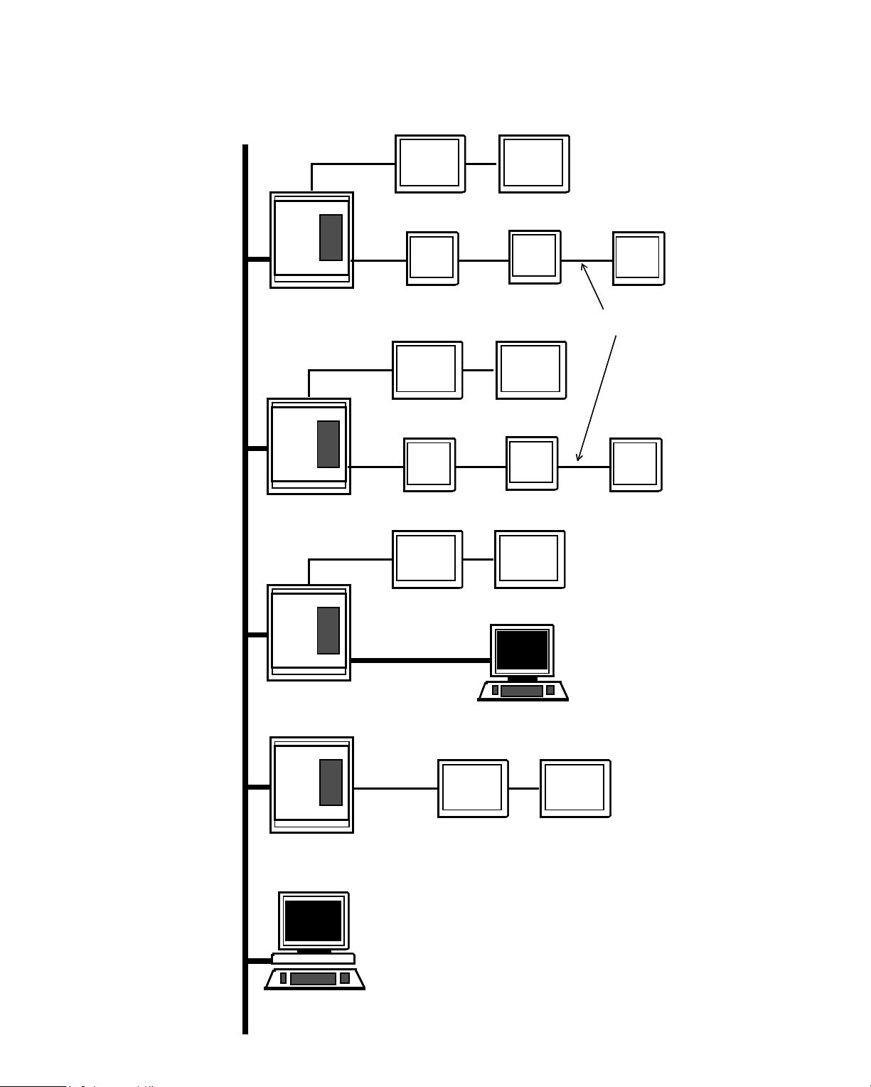
Understandi ng Controller Hardware
Figure 1-1. Sample Map of a Network
EnergyNet
Cable
Infinet
Cable
Infinity CX 9000
Infinity CX 9500
SCX
900
IOU
SCX
900
IOU
SCX
900
IOU
LCX
800
IOU
TCX SCX
850 900
IOU
LBUS Cable
IOU
VT100
Infinity CX 9000
SCX
900
Infinity CX 9500
TCX
850
(has built-in inputs and outputs)
Infinity SX 8000
Infinity Controller Programmer’s Guide 1-3
Page 12

Understanding Controller Hardware
s
s
Knowing about Point Types
Input and Output Point
Each IOU on the controller has 32 universal input sensors and
16 outputs, which may be universal, tristate, or Form C (ON
and OFF). The “universal” inputs and outputs accept input
from and send output to several types of sensors or devices
without any hardware alterations.
We refer to all these sensors and transmitters as input and output points.
Input and output points are
the environment.
An input point is constantly receiving info rmation about, for
instance, the temperature in a room. While that temperature
remains within a set range (say 68 to 72), the controller takes
no action.
If the heat is off and not needed, the controller does not turn it
on. When the temperature drops below 68 or rises above 72,
Infinity
’s way of interacting with
Rules for Naming Point
the point triggers a response from the controller.
Usually, only when a point changes does the controller take
action. Types of points other than inputs and outputs are described in Chapter 5.
Plain English Names
The controller cannot act on a point unless you tell it the name
and location of the point. So you must assign a name to each
point.
Points and other items on the controller can be named with up
to 16 alphabetic and numeric characters, including periods
and underscores. The first character must be alphabetic.
You can enter the name in upper and lowercase the first time
so it is more readable than all caps, but the controller under-
1-4 Infinity Controller Programmer’s Guide
Page 13

Understandi ng Controller Hardware
stands it as the same name in either case. For example, the
controller reads the following two names as the same:
SupplyAir
SUPPLYAIR
The first is obviously easier for you to read. If you enter it that
way the first time, later, even when you enter SUPPLYAIR,
the controller will reprint it on the screen as
SupplyAir
each
time you open the program file.
Procedures to tell the controller the names of all the points are
in Chapter 4.
Locating Controller Points
You might want to make copies of the drawings on the next
few pages, one for each
Infinity CX 9000
IOU and each
Infinet
controller on the network.
The drawings show the input and output points and the nu-
meric labels supplied at by Andover Controls . In your
drawing, you write a name next to each input and output that
defines its purpose. Note which IOUs are tristate, universal, or
Form C.
You can later follow these drawings when setting up points.
If you have many IOUs connected to one
a great many
Infinet
controllers, these drawings may help
Infinity CX 9000
, or
avoid confusion.
Finding Points on IOUs
Infinity Controller Programmer’s Guide 1-5
Page 14
Understanding Controller Hardware
Points on IOUs
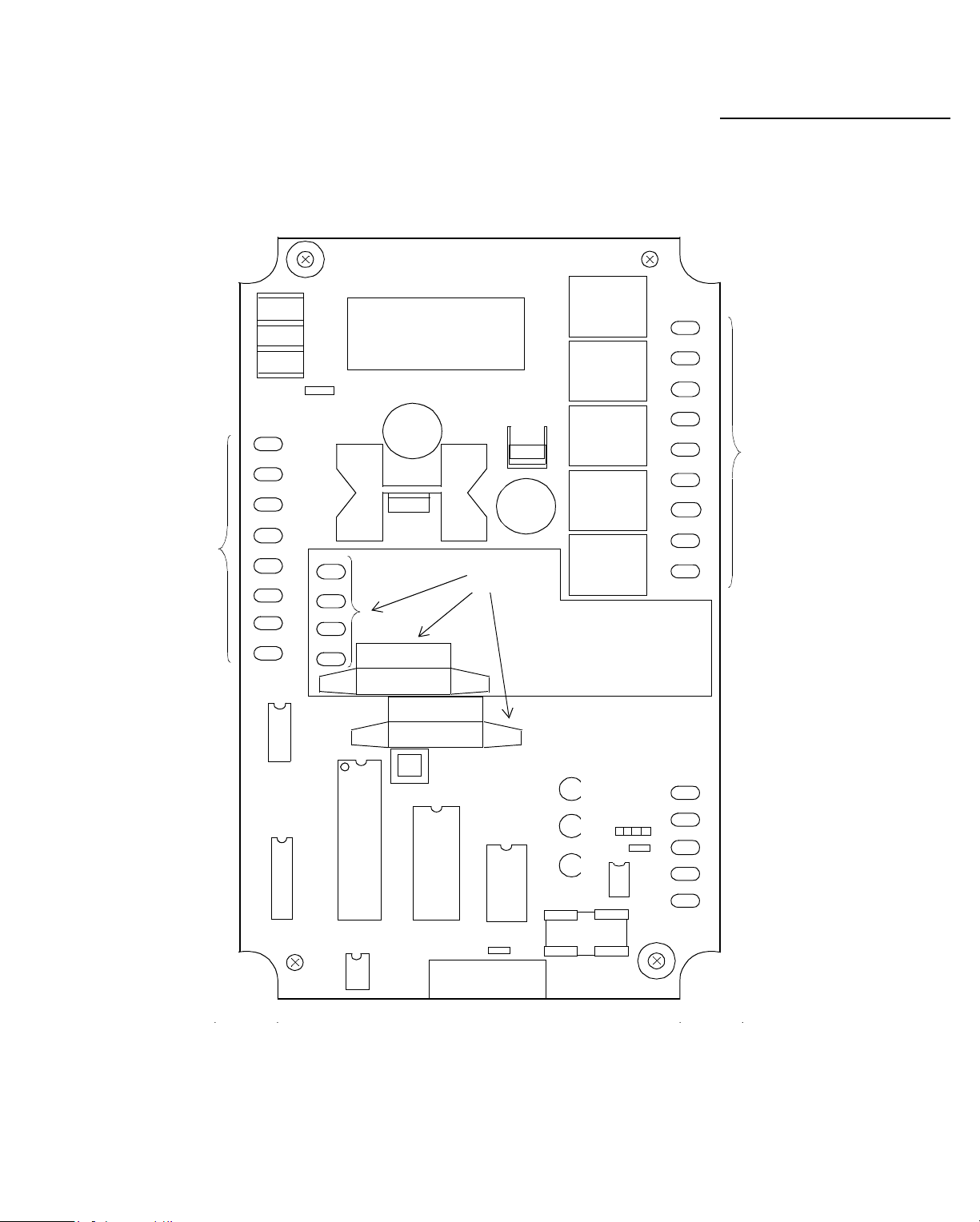
Figure 1-2 is a drawing of an IOU, showing the input and
output points (usually used with
Infinity CX
controllers).
OUTPUTS
OUTPUT
NUMBERS
u
g
2
of
CentralPlant
1Universal Points
IOU Number
i
F
Infinity CX 9000 Name
INPUTS
1-6 Infinity Controller Programmer’s Guide
Page 15
Understandi ng Controller Hardware
T
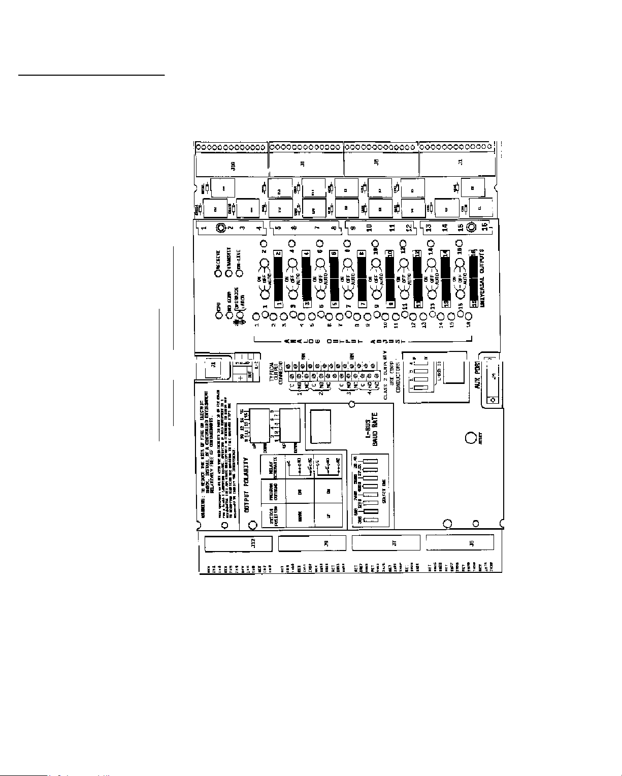
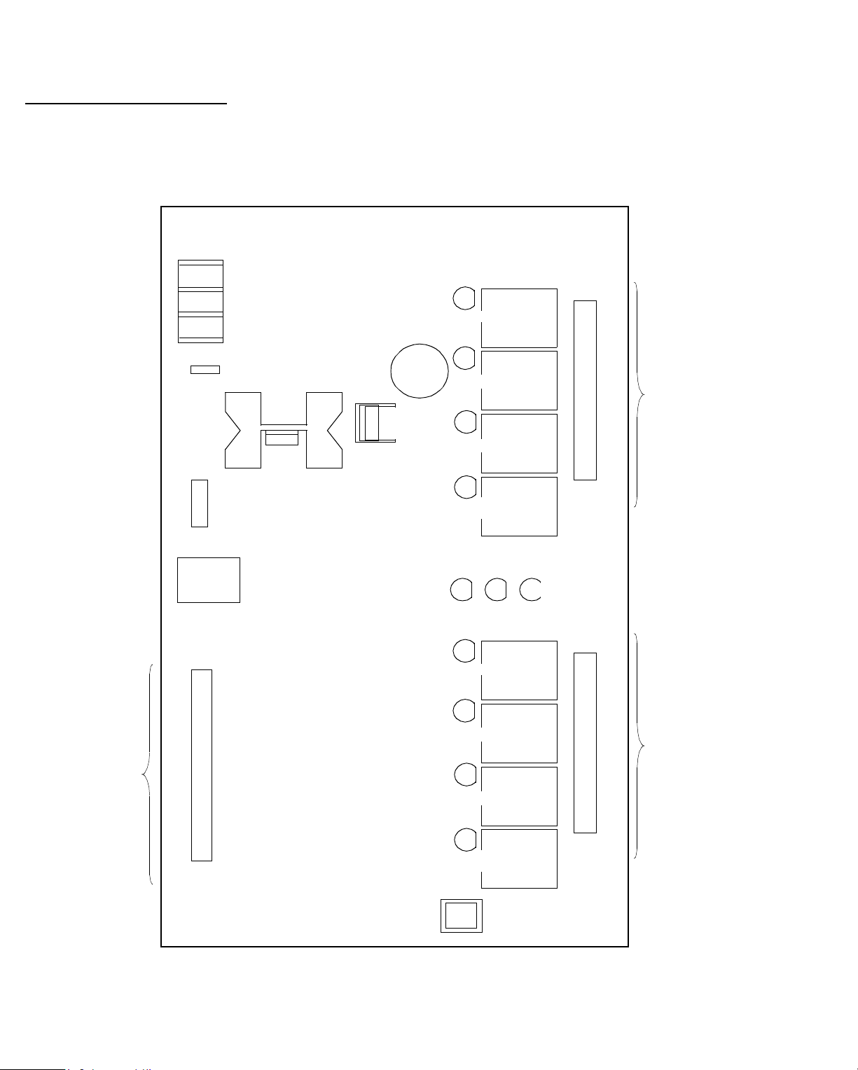
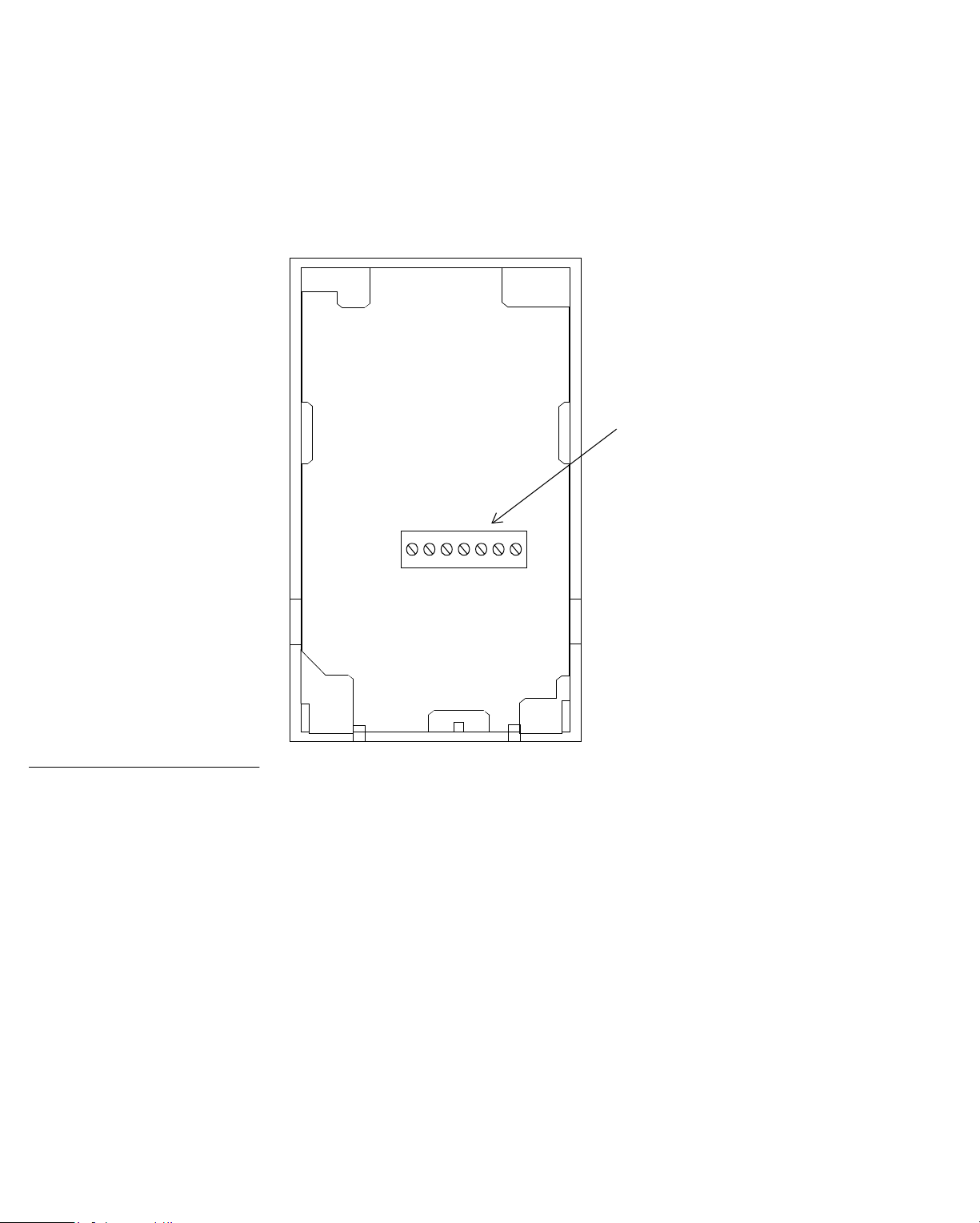
Figure 1-3 is a drawing of a
Infinet
controller,
SCX 900
showing the input and output points.
Figure 1-3. Drawi ng Showing SCX 900 Points
INPUTS
X
AC
INPUT
GND
NEU
HOT
X X X X
X
X
X
X X
X X
X X
xx
SCX
F14
2 A
X
INPUTS
X
RET
X
X
X
X
X
X
X
X
X
X
X
X
X
X
X
X
X
X
X
X
X
X
X
X
X
X
X
1
2
RET
3
4
RET
5
6
RET
7
8
RET
9
10
RET
11
12
RET
13
14
RET
15
16
+
–
SHLD
SERVICE
PORT
INPUT
REFERENCE
RESISTOR
X
X
X
X
X
X
X
X
OUT
INPUT
REFERENCE
RESISTOR
X
x
x
X
x
X
x
X
x
x
X
x
X
x
X
x
x
X
OUT
INFINET
LCD VIEW ANGLE
USE COPPER
CONDUCTORS ONLY
X X
AC INPUT VOLTAGE SELECTION
24V
From
To
From
E1
E1
X X
F19, 3A, 250V
SLOW BLOW
X
X
X
X
X
X
X
X
IN
X
x
x
X
x
X
x
X
x
x
X
x
X
x
X
x
x
X
IN
E3 E4
E2 E5 E2 E2 E7
TP10
TP10
E6 E6 E4
X
X
1
2
3
4
5
6
7
8
9
10
11
12
13
14
15
16
X
X
115V
3.6 V
1/8 A
X
To
E7
+
-
RESET
F1
TP10
X
From
230V
X
x
x
x
x
x
x
x
x
X
To
----
ADJ
X
ADJ
X
ADJ
ADJ
ADJ
ADJ
ADJ
ADJ
- On
x
Off
Auto
Off
+On
- On
x
Off
Auto
Off
+On
-On
x
Off
Auto
Off
+On
- On
x
Off
Auto
Off
+On
-O n
x
Off
Auto
Off
+On
- On
x
Off
Auto
Off
+On
-On
x
Off
Auto
Off
+On
x
X
X
Auto
Off
EXPANSION
PORT
+On
Points on an SCX 900
X
EPROM
1
xx
x
1
2
x
Form C
2
3
4
5
6
7
Tristate
x
STATUS
x
x
x
x
x
x
x
x
OVERRIDE
x
EXTERNAL
x
Form C
Tristate
CPU
TD
RD
+ 24 V
x
x
x
x
x
x
x
x
8
1/8 A
1/8 A
1/8 A
3
4
5
6
7
8
C
X
NO
X
I
X
X
V
X
GND
X
GND
X
I
X
V
X
NC
X
C
X
NO
NC
X
C
X
NO
X
I
X
V
X
GND
X
X
GND
X
I
X
V
X
NC
C
NO
NC
C
NO
I
V
GND
GND
I
V
NC
C
NO
NC
C
NO
I
V
GND
I
V
NC
C
NO
OUTPU
X
X
X
X
X
X
X
X
X
X
X
X
X
X
X
X
X
X
X
X
X
X
X
X
X
X
NC
X
X
Infinity Controller Programmer’s Guide 1-7
Page 16
Understanding Controller Hardware
0
S
Points on an TCX 85
INPUTS
G
N
D
N
E
U
H
O
T
IN1
RET
IN2
RET
IN3
RET
IN4
RET
Figure 1-4 is a drawing of a
output points. The
TCX 851
TCX 85 0
, showing the input and
is similar, but has only the first
four inputs.
Figure 1-4. Drawing Showing TCX 850/851 Points
OUTPUT
C
OUT1
NO
C
OUT2
+
+
IN5 IN6 IN7
MIN
MAX
OUT3
OUT4
SP
NO
C
NO
C
ON
+
–
ON
INPUTS
INPUT 8
+
SHLD
–
+–
1-8 Infinity Controller Programmer’s Guide
Page 17
Understandi ng Controller Hardware
Figure 1-5 shows the
TCX 853
inputs and outputs. The
universal inputs are 5 through 6, the airflow inputs 7 and 8.
Figure 1-5. Drawing Showing TCX 853 Points
G
N
D
N
E
U
H
O
T
+
IN1
RET
IN2
INPUTS
RET
IN3
RET
IN4
RET
IN5
RET
IN6
RET
Inputs
INPUT 7
+
OUT1
OUT2
OUT3
OUT4
+
–
Points on an TCX 853
C
NO
C
NO
C
OUTPUTS
NO
C
ON
ON
INPUT 8
+
SHLD
–
+–
Infinity Controller Programmer’s Guide 1-9
Page 18
Understanding Controller Hardware
0
S
Points on an LCX 80
G
N
D
N
E
U
H
O
T
+
–
SHLD
Figure 1-6 is a drawing of an
LCX 800
, showing the input and
output points.
Figure 1-6. Drawing Showing LCX 800 Points
OUT1
OUT2
OUT3
OUT4
NC
C
NO
NC
C
NO
NC
C
NO
NC
C
NO
OUTPUTS
INPUTS
RET
IN1
IN2
RET
IN3
IN4
RET
IN5
IN6
RET
IN7
IN8
OUT5
OUT6
OUT7
OUT8
NC
C
NO
NC
C
NO
NC
C
NO
NC
C
NO
OUTPUT
1-10 Infinity Controller Programmer’s Guide
Page 19
Understandi ng Controller Hardware
Figure 1-7 is a drawing of an
LCX 810
, showing the input and
output points.
Figure 1-7. Drawing Showing LCX 810 Points
AC
INPUT
GND
NEU
HOT
USE CO PPER
CONDUCTORS ONLY
Points on an LCX 810
INPUTS
xxxxxxxxxxx
xxxxxxxxxxx
INPUTS
RET
1
2
RET
3
4
RET
5
6
RET
7
8
+
–
SHLD
IN
OUT
INFINET
INPUT
REFERENCE
RESISTOR
STATUS
LIGHTS
+
3.6V
–
CPU
TD
RD
OVERRIDE
+24V
EXTERNAL
NC
C
1
NO
NC
C
2
NO
NC
C
3
NO
NC
C
4
NO
OUTPUTS
NC
C
5
NO
NC
C
6
NO
NC
C
7
NO
NC
C
8
NO
SERVICE
PORT
EXPANSION
PORT
Infinity Co ntrol ler Programmer’s G uide 1 -11
Page 20
Understanding Controller Hardware
0
S
Points on an ACX 70
AC
INPUT
GND
NEU
HOT
+12VDC
-INPUT
IN1
RET1
IN2
RET2
IN3
RET3
IN4
RET4
IN5
RET5
IN6
RET6
IN7
RET7
IN8
RET8
EXT
TAMPER
SWITCH
+5V
LED
I/DATA
O/CLK
GND
+5V
LED
I/DATA
O/CLK
GND
+
–
SHLD
SUPERVISORY
TAMPER
SWITCH 9
INFINET
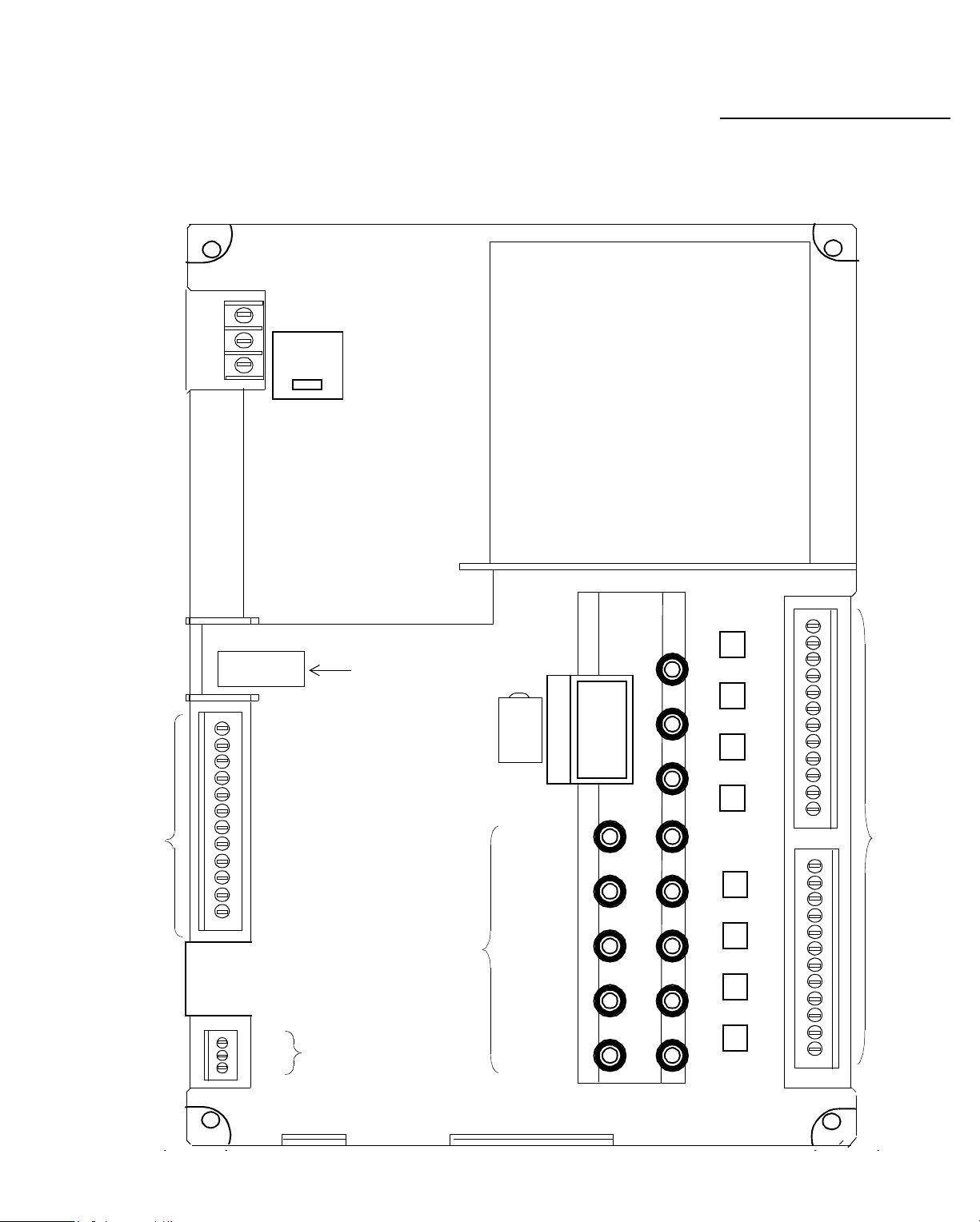
Figure 1-8 shows the
ACX 700
supervisory input points.
Figure 1-8. Drawing Showing ACX 700 Points
USE COPPER
CONDUCTORS
ONLY
AC INPUT VOLTAGE SELECTION
24V
FROM
E6
E4 E3 E4 E4 E5
P1
115V
TO
FROME2TOP1FROM
E6
E7 E5
P1
E1 E1 E2
230V
TO
----
ACX700
F1
3A,250V
SLOW BLOW
PWR
ON
INPUTS
RESET
ABA
WIEGAND
READ ER 1
READ ER 2
ABA
WIEGAND
+
B1
3.6V
1.8AHr
LITHIUM
–
CPU
TD
RD
+24VDC CLASS 11
A
160
m
INPUTS
KEYPAD 1
KEYPAD 2
OVERRIDE
AUTO/OFF/ON
AUTO/OFF/ON
AUTO/OFF/ON
C1
C2
C3
R1
R2
R3
R4
RET
C1
C2
C3
R1
R2
R3
R4
RET
DOOR 1
OUTPUT
DOOR 2
OUTPUT
OUTPUT 3
DOOR
SERVICE
PORT
EXPANSION
PORT
OVERRIDE
1-12 Infinity Controller Programmer’s Guide
Page 21

Understandi ng Controller Hardware
For this special controller, you do not set up ordinary points.
Instead, you set up Doors, as described in Chapters 21, 22,
and 23 of Volume 2. Doors are similar to points. Each door
has a channel number. Door1 is channel 1, Door2 channel 2.
You can also connect a door to Output 3 (channel 3).
You do not set up the card readers or keypads as input points,
but associate a card reader or keypad with a particular door by
assigning the channel number (Reader1 is channel 1, Reader2
is channel 2) to the card reader for the particular door.
You can, in addition, set up the supervisory inputs as input
points. For information about the types of sensor s you can
wire to supervisory inputs, and for more information about
Doors and access control, see Chapters 21, 22, and 23. Refer
to Chapter 4 for how to set up supervisory point types.
1
ACX 700 Has Doors
1. For an alternative method of setting up doors , see Chapter 16.
Infinity Co ntrol ler Programmer’s G uide 1 -13
Page 22
Understanding Controller Hardware
0
Points on an LCX 89
24 VAC
Rectified
Power
Terminal for
Occupancy
Sensor
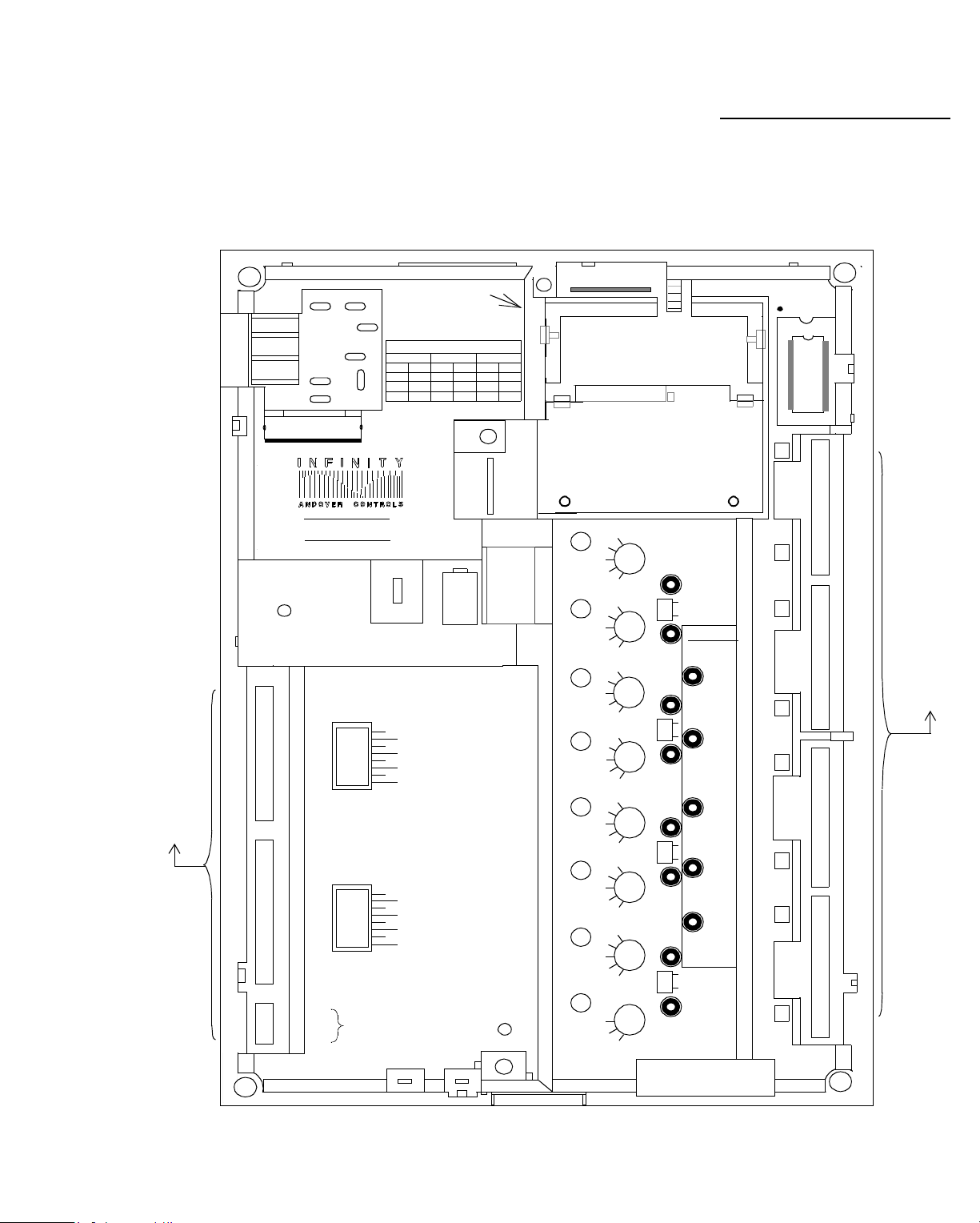
Figure 1-9 is a drawing of an
output points, and the location of the switches for momentary
manual control.
Figure 1-9. Drawing Showing LCX 890 Points
Momentary
Switches
LCX 890
, showing the input and
Output
Relays
(Max Number
Possible
Shown—24)
Universal
Inputs
Digital
Inputs
LCX 890
INPUTS
EMX 170
1-14 Infinity Controller Programmer’s Guide
or
SP 100
Port
Page 23

Understandi ng Controller Hardware
Expansion Module Inputs and Outputs
You may a ttach a limited number of expa nsion modules to each
Infinet
contr oller mo del. Th e numbe r is b ased on the fol lowin g:
Caution—Memory Limitation
You may run out of memory before the maximum number of
expansion points, so keep the number to a minimum.
• Never use more than two of any particular model number.
• The total number of inputs or outputs that are on the
modules must never be more than the number allowed on
Infinet
the
• You must set the first output module on the chain to Board
1, the second to Board 2, the third to Board 1, the fourth to
Board 2, and so on—no matter which model number
modules. When you start the input mo dules, start at
Board 1 again and continue to alternate from 1 to 2.
controller—see the table below.
Attach Limited Number
of Expansion Modules
• A single
Two of them must be the last two output modules on any chain.
•A SmartSensor (
• If all modules attached to a single controller consume
more than 110 mA, you must add an external power supply
to the chain. To determine the milliamps each module consumes and whether or not you require an external power
supply, see the
Based on the table, you can have up to eight expansion
outputs on a
EMX 150
each) on that controller, for a total of eight expansion outputs.
Infinity Co ntrol ler Programmer’s G uide 1 -15
EMX 190
LCX 810
s (two outputs each) and two
must be the last output module on any chain.
EMX 170
ACC EMX Modules Configuration Guid e
) must be the last module on any chain.
. So you can, for example, have two
EMX 155
s (two outputs
.
Page 24

Understanding Controller Hardware
d
You may never have more than two of any single module.
Table 1-1. Number of Base, Expansion Module, and
Total Inputs/Outputs Allowed for Various Controllers
Controller
Model No. Base Exp Total Base Exp Total
TCX 850/851
LCX 810
SCX 900
ACX 700
An alternative would be to have two
outputs each), one
140
(with two outputs). Again, the total is eight expansion
Inputs Outputs
8
8
16 17
8 21
17
17
25
25
33
29 3 4 7
4
8
8
EMX 150
EMX 151
(with two outputs), and one
2
8
8
6
16
16
s (with two
EMX
outputs.
You can mix inputs with outputs so that, in addition to the
outputs, you could have two
sure to put the
EMX 170
at the end of the chain.
EMX 160
s and one
EMX 170
. Be
Setting the Boar
Switches
Note
Note that
EMX 140
give standard feedback indicating when you are controlling the
point manually or what its manual control setting is.
Be sure you set the Board switch of the first module to Board
1, and the second to Board 2 (see illustrations that follow for
location of Board switch) and you put one immediately after
the other. (Never set the first one to Board 2.) The same
applies for every
EMX 190. No matter which Board you just set the last
the
EMX
output module to, you must set the first EMX 190 to Board 1
and the second to Board 2.
last output modules on the chain, you can then switch to input
modules, and start again at Board 1. (Be sure to put together a
150
and
expansion module outputs do not
model that has a Board switch—except
Since the
EMX 190
s must be the
1-16 Infinity Controller Programmer’s Guide
Page 25
Understandi ng Controller Hardware
map showing the chain of
EMX
modules for each
Infinet
controller using them.)
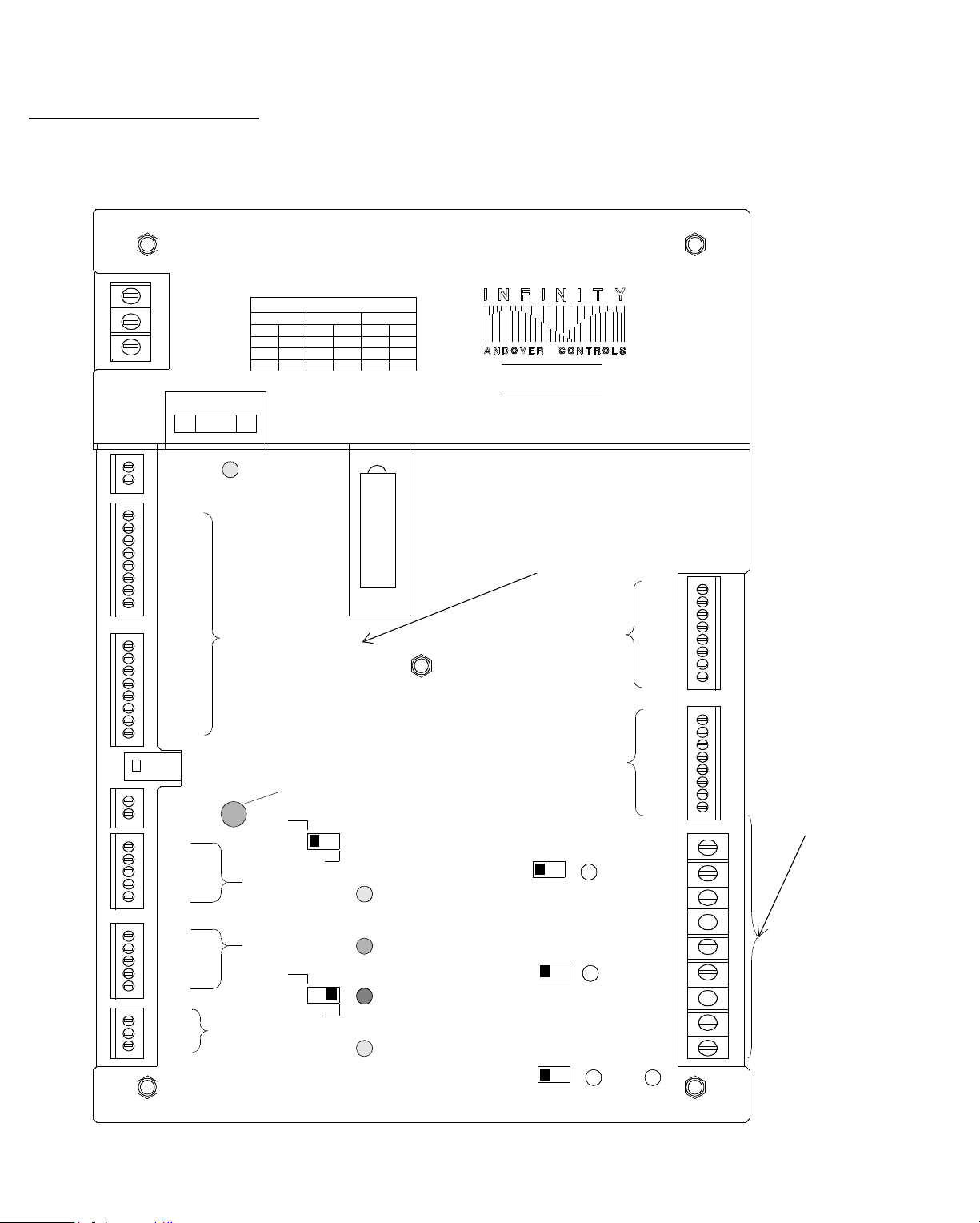
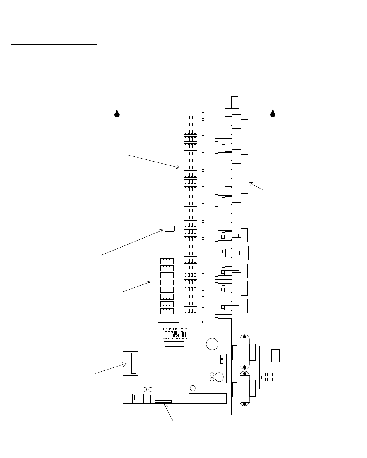
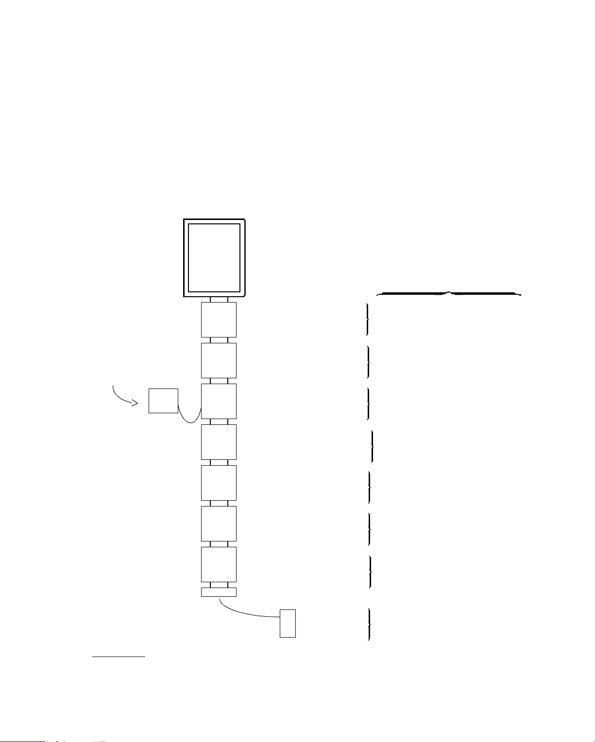
Figure 1-10 illustrates a sample map of
SCX 900
controller, using the maximum number of inputs and
EMX
modules on an
outputs allowed. (You assign input and output numbers later,
in Chapter 4.)
Figure 1-10. Sample of EMX Modules on an SCX 900
You assign these output
SCX
900
EMX 150
2 Outputs
—Board 1
numbers very carefully,
as covered in Chapter 4.
Output 9—Voltage
Output 10—Voltage
External
Power
Supply
EMX 150
2 Outputs
—Board 2
Output 11—Current
Output 12—Current
EMX 140
—Board 1
2 Outputs
EMX 190
—Board 1
1 Output
EMX 190
—Board 2
1 Output
EMX 160
—Board 1
8 Digital Inputs
EMX 160
—Board 2
8 Digital Inputs
EMX 170
—1 Input
1
Even if you do not have a second pneumatic output (as on an
count outputs as if it were there.
Output 13—Pneumatic
Output 14—Pneumatic
Output 15—ReaderDoor
Output 16—ReaderDoor
Inputs 17–24—Digital
Inputs 25–32—Digital
Input 33—Temperature
EMX 141
or
EMX 143
), you must
1
Infinity Co ntrol ler Programmer’s G uide 1 -17
Page 26
Understanding Controller Hardware
0
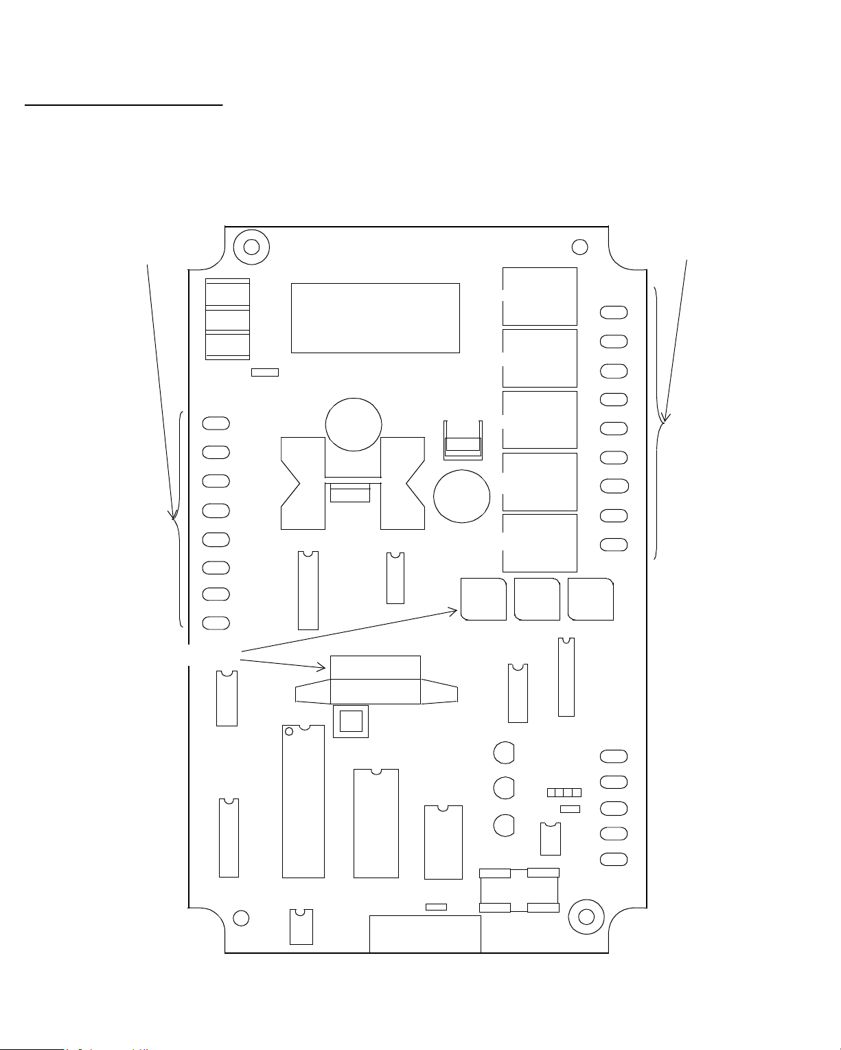
Points on an EMX 16
Figure 1-11 is a drawing of an
EMX 160
input module,
showing the inputs, labeled 1 through 8. The inputs can be
digital or counter.
You number the inputs on the module sequentially after the
highest input number on the
For instance, if you put the module on an
Infinet
controller it is attached to.
SCX 900
, the Board
1 module would have inputs 17 through 24, and the Board 2
module would have inputs 25 through 32.
Figure 1-11. Drawing Showing EMX 160 Points
EMX 160
BOARD
1
2
INPUTS
EXTERNAL
POWER
RET
IN1
IN2
RET
IN3
IN4
RET
IN5
IN6
RET
IN7
IN8
1-18 Infinity Controller Programmer’s Guide
Page 27
Understandi ng Controller Hardware
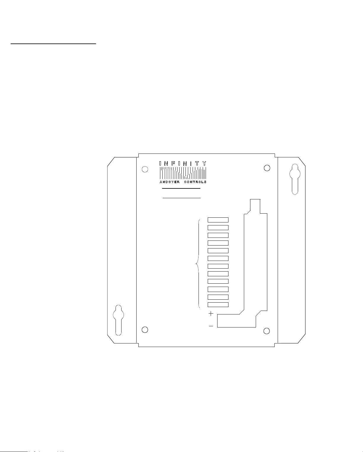
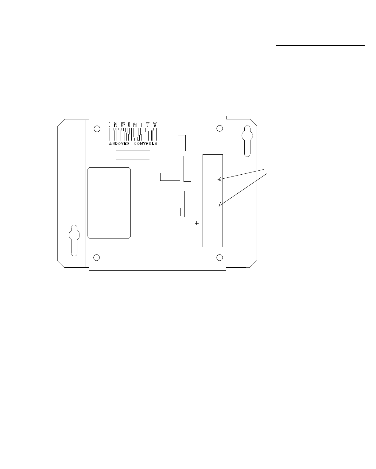
Figure 1-12 is a drawing of an
EMX 150
output module,
showing the outputs, labeled A and B. The outputs can be
voltage or current.
You number the outputs sequentially after the highest output
number on the
module on a
Infinet
TCX 850
controller. For instance, if you put the
, the Board 1 module would have outputs 5 and 6, and the Board 2 module would have outputs 7
and 8.
The two knobs adjust the two outputs between 0 and 20 V.
You can set the override switch to manual or automatic. You
cannot, however, get feedback through the controller telling
you that either of these outputs is set to manual control with
the OVERRIDE switch or telling what the override setting is.
Figure 1-12. Drawing Showing EMX 150 Points
Points on an EMX 150
EMX150
OVERRIDE
A
AUTO MAN
B
A
B
BOARD
1
2
OUTPUT
A
OUTPUT
B
RET
I
V
OUTPUTS
RET
I
V
Infinity Co ntrol ler Programmer’s G uide 1 -19
Page 28
Understanding Controller Hardware
s
t
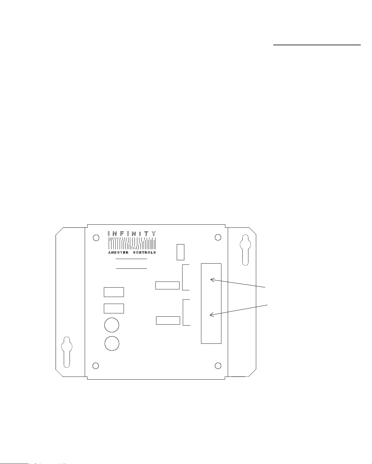
Figure 1-13 is a drawing of an
EMX 170
SmartSensor module.
This module has a single temperature input.
Figure 1-13. Drawing Showing
the EMX 170 Point
A SINGLE INPUT
EMX 170 Input I
Temperature Inpu
The input on the
EMX 170
is automatically the only
temperature input point number assigned after the original
inputs on the controller. Even if you have no other expansion
module, you must always assign the
EMX 170
sensor the
highest possible input number in the entire chain of modules.
(On
SCX
controllers, number 33. On
LCX
and
TCX
controllers, number 25.)
1-20 Infinity Controller Programmer’s Guide
Page 29
Understandi ng Controller Hardware
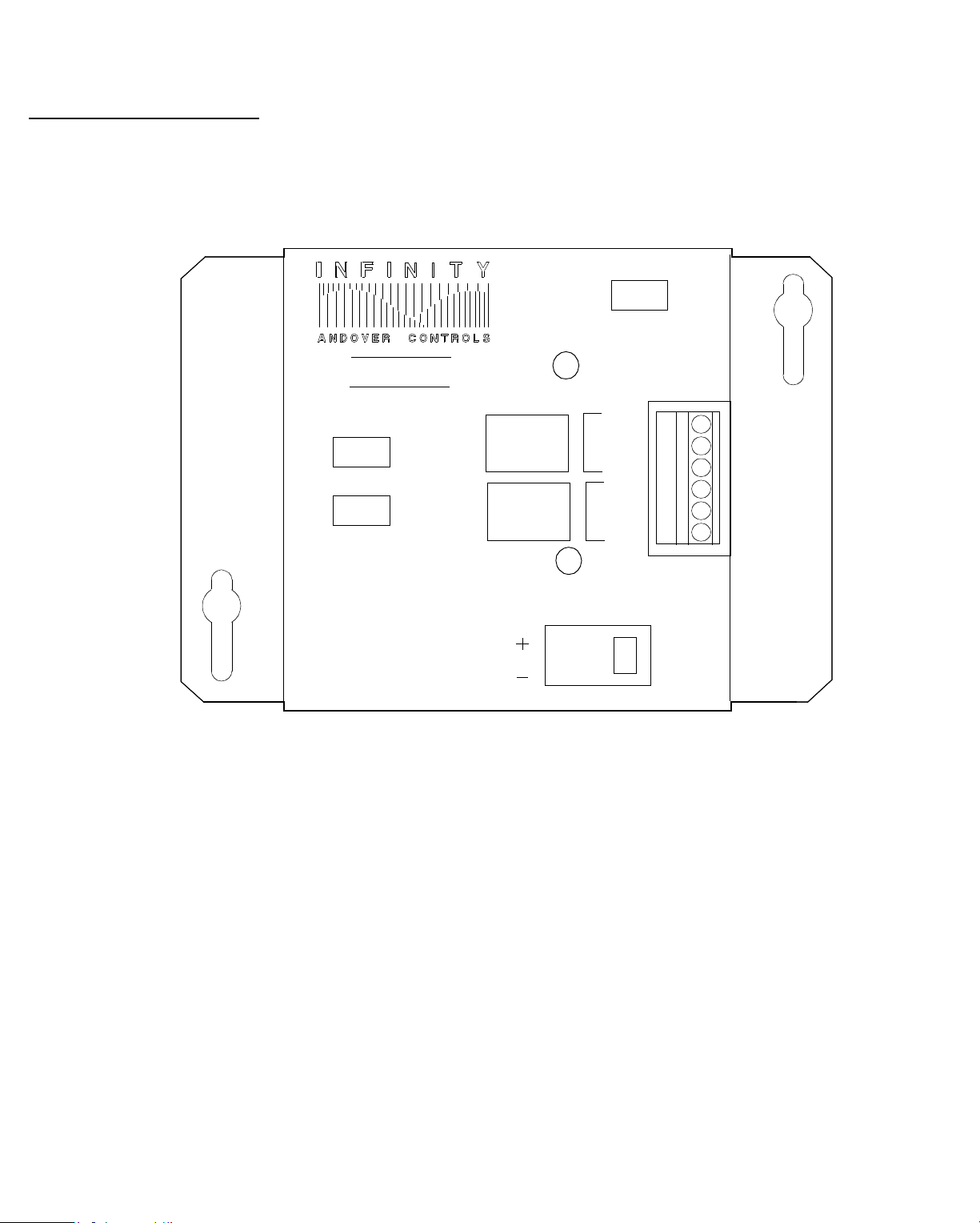
Figure 1-14 is a drawing of an
EMX 151
module. This module
has two analog outputs that must be controlled by the
controller because they have no manual override switches.
You can use one or two modules of this type in a single chain.
Figure 1-14. Drawing Showing EMX 151 Points
BOARD
1
OUTPUT
A
OUTPUT
B
2
RET
I
V
RET
I
V
EMX151
Points on an EMX 151
OUTPUTS
EXTERNAL
POWER
Infinity Co ntrol ler Programmer’s G uide 1 -21
Page 30
Understanding Controller Hardware
5
Points on an EMX 15
Figure 1-15 is a drawing of an
EMX 155
module. This module
has two Form C outputs. You can use one or two modules of
this type in a single chain.
Figure 1-15. Drawing Showing EMX 155 Points
BOARD
1
2
EMX155
OUTPUT A
OVERRIDE
AUTO
OFF
A
ON
B
OUTPUT
NC
C
NO
NC
C
NO
B
EXTERNAL
POWER
1-22 Infinity Controller Programmer’s Guide
Page 31

Understandi ng Controller Hardware
Figure 1-16 is a drawing of an
has a single output.
Infinity
EMX 190
module. This module
identifies all the inputs wired to
the module in terms of the output.
EMX 190
The
chain. If you have one, it must be Board 1. If you have two
EMX 190
must always be the last output module on the
s they must be the last two output modules and they
must be Board 1, then Board 2, no matter which board number
precedes them.
Figure 1-16. Drawing Showing EMX 190 Points
EMX190
BOARD
1
2
DOOR SWITCH
RTN
EXIT REQUEST
RTN
Points on an EMX 190
ReaderDoor
OVERRIDE
ON
WIEGAND
CARD READER
Output
OFF
CARD
READER
INPUT
AUTO
ABA
OVERRIDE
1/DATA
DOOR
OUTPUT
RTN
0-CLK
LED
+5V
NC
C
NO
24VDC
CLASS
II
Infinity Co ntrol ler Programmer’s G uide 1 -23
Page 32

Understanding Controller Hardware
0
Points on an EMX 14
Figure 1-17 is a drawing of an
EMX 140
module. This module
has two pneumatic outputs. You can manually override this
output by removing the air flow tube. The controller does not
give you feedback telling you the output is being manually
controlled, but it does give you the value of the output when
you have it in this “manual override” state.
Figure 1-17. Drawing Showing EMX 140 Points
EMX140
CHANNEL CHANNEL
A
B
OUT
SUPPLY AIR
PNEUMATIC
OUTPUTS
EXTERNAL
POWER
+
–
0-20
MA
RET
SUPPLY AIR
RET
A
IN
OUT
BOARD
12
B
IN
1-24 Infinity Controller Programmer’s Guide
Page 33

Understandi ng Controller Hardware
You can purchase variations on this module with only one
pneumatic output, but you must treat those models as if they
have two by skipping an output for the second one.
So, if you assign a single pneumatic output the number 13,
then you cannot assign 14 to another module. Skip 14 and assign 15 to the next module output.
EMX 140 Modules Have
One or Two Outputs
Infinity Co ntrol ler Programmer’s G uide 1 -25
Page 34

Understanding Controller Hardware
r
Small Network Controllers
Small Networks Can
Employ CMX Contro lle
In certain situations, you may require only a single
EnergyNet
no
. These situations would be sites with few con-
Infinet
and
trollers and/or few programs (since the memory available in
Infinet
any
controller is limited). You may want to call such a
site to monitor it.
For a single
nal, you may want to employ the
Infinity CMX
The
CMX
has the following features/ limitations:
• A port for an
Infinet
where you do not always require a termi-
is a scaled down
Infinet
Infinity CMX
Infinity CX
that can have up to 32
controller.
. The
Infinet
Infinity
controllers.
• An RS-232 port you can use for two purposes, but only one
at time:
— Built-in modem automatically set to 2400 baud.
— A terminal.
When you set up the port as a UserPort, you set it up for a
terminal. However, when another party (such as another
site or an operator in another building) calls in over the
modem, the modem always takes control of the port.
Once a modem call occurs, the controller automatically
logs you (or any other operator) out of the terminal and
closes any open files. If you have been altering a program
and have not saved it when the modem call occurs, you
lose the changes.
1-26 Infinity Controller Programmer’s Guide
Page 35

Understandi ng Controller Hardware
When to Use CMX Controllers
Andover recommends that you use an
CMX
controller with a
terminal only in situations where you do not expect the terminal and the modem to conflict with one another. For instance,
here are some possible situations:
• If you are calling in on the modem only after 5 p.m., when
the operator is no longer using the terminal.
• If you intend to construct a dump file for the
CMX
on
another controller and then load it, rather than developing
programs on the controller at its terminal.
CMX Terminal and
Modem Can Conflict
Infinity Co ntrol ler Programmer’s G uide 1 -27
Page 36

Understanding Controller Hardware
1-28 Infinity Controller Programmer’s Guide
Page 37

Chapter 2
Logging On and Setting Up
EnergyNet and Infinet
We recommend you read this chapter sequentially to get
started on an
terminal and carry out all of these procedures to set up the
Infinity CX
or
CMX
controller. Go to the
controllers on each
• Logging on for the First Time
• Using the Command Window
• Printing in the Command Window
• Using the Menus
• Setting the Date and Time
• Making Changes Inside the Window
• Defining
• Setting Contro ller Attributes
• Defining the
• Setting
• Opening
• Understanding
• Accessing (Connecting to) Other Controllers
• An Alternative Method of Connecting to Other Controllers
Infinity CX
Infinet
Infinet
EnergyNet
Controllers
Infinet
Attributes and Finding Controllers
Controller Network
Controllers
Infinet
Controller Attributes
and
Infinet
:
Note
Keystrok es are uniqu e for e ach term inal type . Thi s manual us es
standard ke y n ames. Y ou can look up the s pecific keys troke s for
your terminal in the
Appendix A . Keep the reference card by your terminal until yo u
are well ac quainted wi th the keys trok es. Note that you ma y use
some keys differently in differe nt situatio ns.
Keystroke Refer ence
card (encl osed) or in
Page 38

Setting Up EnergyNet/Infinet
e
w
Logging On for the First Time
Terminal Displays th
Infinity Windo
Once you have installed the hardware, when you first approach
any terminal or computer on an
screen is blank. You activate
Infinity CX
Infinity CX
controller, the
windows as follows:
1. Type WINDOW. The word does not appear on the screen.
Instead, a box appears that takes up most of the screen. The
box is c a lle d a “window.” (If you do n ot have w indows, go
to Logging On without Windows on the next page.)
Figure 2-1 shows the
Infinity
window.
Figure 2-1. Infinity Window
View Edit Connect Logout
Infinity
(C) 1990 Andover Controls Corporation
Version 1.2
User Name
Password
In the center of the window are two smaller boxes (text
boxes), one labeled
User Name
and the other
Password
Since you, the system administrator, are the first user, you
must enter the predefined user logon
ACC
and the
password provided with your hardware.
The cursor (the blinking box) should be at the beginning of
User Name
the
text box.
.
2-2 Infinity Controller Program mer’ s Gu id e
Page 39

Setting Up EnergyNet/Infinet
2. Type
ACC
in the first text box and press the NEXT
ATTRIBUTE key to move to the next text box. (Or arrow
to it with the down arrow key.)
3. Type your password in the second text box.
To prevent others from seeing the password, the controller
does not show the word as you type it.
4. Press the EXECUTE key to proceed.
A new window should appear on the screen. The
EXECUTE key always moves on to the next window or
completes an action.
You are now ready to proceed with the next section.
If the window does not appear, you may have made a mistake
typing the password. Try logging on again. If you continue to
fail, contact your Andover Controls representative.
Passwords Do Not
Display
Logging on without Windows
If you have an
the controller from a blank screen so that you can work with
dump files:
1. Type C OM MA ND . T he w ord does no t a ppear on t he
screen. Instead,
2. Type
ACC
not appear on the screen.
3. Type
ACC
make a mistake in the password,
you must enter the logon and password again.
When you have logged on successfully, the R> prompt
appears.
Infinity CX 9100
Login:
appears.
and press the EXECUTE key. The
controller, you can log on to
ACC
Password:
appears.
does
again and press the EXECUTE key. If you
Login :
appears again and
If you cannot log on successfully, contact your Andover
Controls representative.
Infinity Controller Programmer’s Guide 2-3
Page 40

Setting Up EnergyNet/Infinet
w
Using the Command Window
The Command Windo
As soon as you have logged on to the controller, a window
inside the main window appears. This is called the
Command
“
Figure 2-2 shows that window. The cursor is on
window.”
View
the fa r
left selection on the Main menu bar. The Main menu bar is the
narrow strip across the top of the sc reen. To move the cursor
from the Main menu bar to the
CANCEL WINDOW key (see the
Command
window, press the
Keystroke Quick Reference
card). To bring it back to the menu bar, press CANCEL
WINDOW again.
In the
Command
window you can enter single-line
instructions called “command lines.” Command lines tell the
controller to do some thing now.
Figure 2-2. Comman d Window of the FLOOR1
Control ler
View Edit Connect Logout
Command Window – FLOOR1
R>
You can use most keywords on the command line. In the
Andover Controls Plain English Language Ref erence,
keyword has a section labeled
Modes Available In
each
. If
“command line” is listed, the keyword can be used on the
command line.
2-4 Infinity Controller Program mer’ s Gu id e
Page 41

Setting Up EnergyNet/Infinet
A PRINT Command Line
You can find out the date using a keyword called PRINT. To
print, for instan ce , the da te, type
PRINT DATE
R>
after the
prompt and press the EXECUTE key.
Figure 2-3 shows that the date prints immediately.
Figure 2-3. Printing the Date on Command Line
View Edit Connect Logout
Command Window – FLOOR1
R> PRINT DATE
June 23, 1992 2:25:51
R>
Print the Date
If the date is incorrect, you change it as described later in this
chapter.
Proceed with the next section to print more information.
Summary
• Command lines tell the contr olle r to act now.
• You can use keywords to form command lines.
• You type command lines after the R>.
Infinity Controller Programmer’s Guide 2-5
Page 42

Setting Up EnergyNet/Infinet
e
s
Printing in the Command Window
Print System Variabl
Value
You can use the PRINT keyword to print the following
predefined names in the
TOD HOUR M IN UTE SECOND
Each of these is already defined by the controller. They are
called “system variables,” because the controller system
keeps track of their values.
To print the time of day (TOD) enter this command line:
PRINT TOD
To print the current hour, minute, or second, enter one of these
command lines:
PRINT HOUR
PRINT MINUTE
Command
window:
PRINT SECOND
Figure 2-4 shows the commands in the window.
Remember not to type the
may type.
To print TOD again, press the up arrow key until the cursor
lands on the command line that says PRINT TOD. Then press
the EXE CUTE ke y .
R>
. The
R>
indicates where you
2-6 Infinity Controller Program mer’ s Gu id e
Page 43

Setting Up EnergyNet/Infinet
Figure 2-4. PRINT Command Lines
View Edit Connect Logout
Command Window – FLOO R1
R> PRINT TOD
8:30 am
R> PRINT HOUR
8
R> PRINT MINUTE
30
R> PRINT SECOND
22
R>
Notice that PRINT TOD reappe ars below all the other
command lines along with the new time.
Now that you have seen how to get information from the
controller, proceed to the next section to see how to put it into
the controller.
Summary
• You can use the PRINT command to print predefined
names in the
• Predefined names are called “system variables.”
• TOD, HOUR, MINUTE, and SECOND are system
variables.
• Type command lines after the
Command
window.
R>
that appears.
Use the PRINT Keyword
• Repeat a command line by moving the cursor back up to
the command line and pressing the EXECUTE key.
Infinity Controller Programmer’s Guide 2-7
Page 44

Using the Menus
r
Setting Up EnergyNet/Infinet
The Main Menu Ba
Across the top of the screen is a 1/4-inch wide bar called the
“Main menu bar.” Each word along that bar is the name of a
menu.
Figure 2-5 shows the Main menu bar, a pulldown menu, and
the status bar. (Your status bar may be different from the one
shown here.)
Figure 2-5. Main Menu Bar, Pulldown Menu, and
Status Bar
View
Edit Connect Logout
Users
Points
Files
CommPorts
Controller
Infinet Controller
System Date & Time
System Variables
Persons
Areas
Doors
MAIN MENU BAR
PULLDOWN
MENU
STATUS BAR
Messages 0 CX: BoilerRm October 24 1992 08:23:45
1. To move the cursor along the menu bar, you press the right
and left arrow keys.
2. To select a menu, press the EXECUTE key while the name
is highlighted.
OR
To both move the cursor to the menu and select the menu
at once, press the first letter of the menu name on the
keyboard. For example, as in the figure above, you press
2-8 Infinity Controller Program mer’ s Gu id e
Page 45

Setting Up EnergyNet/Infinet
E
and the
Edit
menu pulls down. This type of menu is
called a “pulldown” menu.
3. To select an item from any pulldown menu, you arrow to
it using the up and down arrow keys, until it is highlighted.
Then press the EXECUTE key.
OR
4. Press the key for the first highlighted letter in that menu
item. (The first highlighted letter is not always the first
letter of the word.)
Throughout this book when you are directed to select from
a menu, we say “select
select the
Edit
menu, then the
Edit Points
Points
,” because you first
menu item.
In the next section, you set the time and date by opening
System Date & Time
the
window with through the
menus.
Selecting from the
Pulldown Menu
Summary
• The bar across the top of the screen is the “menu bar” and
contains the names of several menus.
• The menus that pull down from the bar are called
“pulldown menus.”
• To select a menu from the menu bar you press either the
arrow and EXECUTE keys or the first letter in the menu
name.
• To select a pulldown menu item pres s either the arrow and
EXECUTE keys or the key for the first highlighted letter
in the item.
Infinity Controller Programmer’s Guide 2-9
Page 46

Setting Up EnergyNet/Infinet
e
Setting the Date and Time
Set the System Tim
Before you do anything else, you must set the date and time
for your controller. (Later, when you set up other controllers,
you can easily send them the same date and time. This way,
you set the date and time only once.)
Select
Edit System Date & Time
from the menu bar.
Figure 2-6 shows selecting from the pulld own menu.
Figure 2-6. Selecting Edit System Date & Time
View
Edit Connect Logout
Users
Points
Files
CommPorts
Controller
Infinet Controller
System Date & Time
System Variables
Persons
Areas
Doors
Messages 0 CX: BoilerRm October 24 1992 08:23:45
Figure 2-7 shows the window that appears after you press the
EXECUTE key. The cursor is in the
Date and Time
box. You enter both the date and time on that line.
You can press the DELETE LINE/TEXT key (refer to the
Infinity CX Keystroke Quick R eference
) to erase the date and
time from the text box. The cursor should then be at the
beginning of the box. You now enter the new date and time all
in the same box.
If, after erasing it, you want to bring the original date and time
back, press the RESTORE TEXT key.
2-10 Infinity Controller Programmer’s Guide
text
Page 47

Setting Up EnergyNet/Infinet
Figure 2-7. System Time Wi ndow
View Edit Connect Logout
System Time – FLOOR1 DATE
Date and Time
August 20, 1990 13:30:26
OK CANCEL
If you want to delete only the time (the last few characters in
the text box), arrow over to the first letter to remove and press
the DELETE TO RIGHT key. Characters to the right of the
cursor erase. You can then type the new time.
More ways to move the cursor in this window and others are
explained in the section called Making Changes Inside the
Window, later in this chapter.
Setting Date
Press Certain Keys
to Erase/Restore Text
You may enter the date using all numbers or spelling the
month as either the full word or the three -l ette r a bbreviation.
You can separate the month, day, and yea r with space s,
slashes, dashes, periods, commas, or any combination of them.
Setting Day and Month
If you enter 3-2-92, the controller automatically interprets it
as March 2, 1992, rather than as February 3, 1992. You can,
however, enter the day first if you:
• Spell the month as a word.
Infinity Controller Programmer’s Guide 2-11
Page 48

Setting Up EnergyNet/Infinet
r
s
• Use numbers for both month and day only if the day is
greater than 12, since any number between 1 and 12 could
be a month. (So, 15-12-90 becomes December 15, 1990.)
Setting Year
The Year May Be Two o
Four Digit
You may enter the year as a two- or four-digit year. You may
enter it before or after the day or month.
Sample Dates
Input Output
9 January 1992 January 9, 1992
92 8 Mar March 8, 1992
91, July 6 July 6, 1991
91-8-Apr April 8, 1991
9/22/91 September 22, 1991
Setting Time
You must keep hours, minutes, and seconds together when
you enter the time, but you do not have to enter seconds.
You can enter the time as 24-hour time or include AM or PM
with the 12-hour time:
Input Output
14:24:09 14:24:09
9:25 PM 21:25:20
10:30:22 AM 10:30:22
1:24:36 PM 13:24:36
You can enter AM or PM anywhere in the date-time.
The controller translates 12-hour time into the 24-hour clock.
For instance, 3:00 PM becomes 15:00:00.
2-12 Infinity Controller Programmer’s Guide
Page 49

Setting Up EnergyNet/Infinet
Sample Date and Time Input
Input Output
July 92, 8 PM 9:25 July 8, 1992 21:25:00
91, Aug 6 8:52:35 P M August 6, 1991 20:52:35
9/22/91 6:6 PM September 22, 1991 18:06:00
AM 9 Jan 1990 6:00 January 9, 1990 6:00:00
Steps to Completing the Date and Time
1. Enter the complete date and time in the
text box.
You must enter a complete and acceptable date and time
before the controller lets you leave the
text box.
2. Press the NEXT ATTRIBUTE key to move to the OK
button and press the EXECUTE key to execute the
process. If you press the CANCEL button, the time reverts
to what it was before.
The date and time are stored in the controller’s memory.
The cursor returns to the menu bar.
You can also press EXECUTE from the
text box at any time to save and close the window, just as
you did in the
User
window. Or you can press the SAVE
Date and Time
Date and Time
Date and Ti me
Change and Check the
Date and Time
key.
3. Select
Notice that the date and time have changed to the one you
entered.
The next section covers how to move around and erase/add
text in the windows. You learn the keystrokes in the quick
reference card as you proceed.
Infinity Controller Programmer’s Guide 2-13
Edit System Date & Time
from the menu bar.
Page 50

Setting Up EnergyNet/Infinet
n
w
Making Changes Inside the Window
Alter User Attributes i
the Windo
Below is how to make changes inside all windows in the
Infinity CX
quick reference card for exact keystrokes.)
, including
Open
and
Edit
windows. (Refer to the
Erasing Text
To erase all text while the cursor is in the text box, press the
DELETE LINE/TEXT key. The cursor lands to the far left.
Moving to Left/Right Side of Text Box
To move the cursor to the far left of the text box without
erasing the text, press the LEFT SIDE key.
To move the cursor to the far right of the text box without
erasing the text, press the RIGHT SIDE key.
Restoring Text
If, after erasing or changing it, you want to bring the text back,
press the RESTORE TEXT key.
Deleting Text
To delete text in front of the cursor (to the right) one character
at a time, press the DELETE TEXT key.
To delete text in back of the cursor (to the left) one character
at a time, press the BACKSPACE key.
To delete only character s to the right of the cursor, arrow over to
the first letter to remove and press the DELETE TO RIGHT key.
Canceling the Information
To cancel the information in the window, press CANCEL
WINDOW or MENU BAR. The window closes, and the
cursor retu rns to th e Main me nu ba r.
2-14 Infinity Controller Programmer’s Guide
Page 51

Setting Up EnergyNet/Infinet
Inserting Additional Text
To insert additional characters in the text box without
overwriting current ones, press the INSERT TEXT key.
Saving Information and C losing Window
To save change s, you can press the SAVE key. Or you can press
the EXECUTE button from any location in the window except
on a button other than SAVE. Or press the SAVE button.
Table 2-1. Keys to Edit Attributes in Windows
Key or Keys Action
Arrow Keys Move the cursor left and right or up
and down a list of selections.
DELETE LINE /TEXT Erases all text in the text box the cur-
sor is in.
RESTORE TEXT Returns text in text bo x to what it was
before you changed it.
BACKSPACE Erases the single character that ap-
pears before it. (Erases backward).
INSERT TEXT
DELETE TEXT
When you press it, then type, inserts
text where cursor is in text box.
Erases the single character that appears after it. (Erases forward).
EXECUTE Can Also Save
Attributes
LEFT SIDE
RIGHT SIDE Moves cursor to right side of text box.
DELETE TO RIG HT Deletes text to right of cursor.
NEXT ATTRIBUTE Moves cursor forward one attribute.
PREVIOUS
ATTRIBUTE
CANCEL WINDOW
or MENU BAR
EXECUTE or SAVE Saves all attributes. EXECUTE
Moves cursor to left side of text box.
Moves cursor back one attribute.
Closes window and erases change s.
Then returns cursor to menu bar.
saves if not on a button that directs
another action.
To set up controllers, pr ocee d to the next sec tion.
Infinity Controller Programmer’s Guide 2-15
Page 52

Setting Up EnergyNet/Infinet
a
e
Defining Infinity CX Controllers
Give Each Controller
Nam
(If you are working on an
Infinity CMX
controller, you may
skip this section and the next one—these steps are optional.
Begin, instead with Defining the
Infinity CX 9000
The
s and
Infinity CX 9500
of controllers are all connected by a cable called
Infinet
Controller Network.)
s on your network
EnergyNet
In the menu, we call the contro lle rs on this cable si mply
Controllers
Infinet
controllers .
Before the
, while we call the other family of controllers
Infinity CX
controllers can interact, each has to
know about the others. To tell all controllers about all other
Infinity CX
controllers on the
EnergyNet
, proceed as follows:
1. Refer to your network map. You need to know the name
and DIP switch setting of each controller.
2. Select
Edit Controllers
from the Main menu bar.
.
Figure 2-8 shows the menu.
Figure 2-8. Selecting Edit Controllers
View Edit Connect Logout
Users
Points
Files
CommPorts
Controllers
Infinet Controller s
System Date & Time
System Variables
Persons
Areas
Doors
2-16 Infinity Controller Programmer’s Guide
Page 53

Setting Up EnergyNet/Infinet
Figure 2-9 shows the
Open a Controller
window.
Figure 2-9. Open a Controller Window
View Edit Connect Logout
Open a Controller
Controller
3. Find the name of your controller on the network map.
4. Enter the name from the network map into the
Controller
text box and press the EXECUTE key.
Open a Controller
Window
Controller
The
window appears. You fill in the
information about the controller as explained in the next
section.
Although they are not on the
230
models are also “controllers” that function like
CX
controllers, so you can enter information about them as
described here for other
Infinity CX
EnergyNet
controllers; however, you
do not have to. The information is optional for
, the
CMX 220
Infinity
CMX
controllers.
and
Infinity Controller Programmer’s Guide 2-17
Page 54

Setting Up EnergyNet/Infinet
r
s
Setting Controller Attributes
Set EnergyNet Controlle
Attri but e
Ether n et ID
Appears Only
for 9200
Controllers
Figure 2-10 shows the
Controller
window.
Figure 2-10. Controller Window
View Edit Connect Logout
Controller – Floor1
SAVE
Name
Description
Ser ial Number
Model
Status
EnergyNet ID
EthernetId
Floor1
CANCEL
DELETE
VIEW
TEACH
0:40:11:0:0:2
RESET
Notice that each text box is labeled: NAME, DESCRIPT ION,
MODEL, and so on. These labels are called “attributes.”
The attribute name, as stored in the controller, may differ
from the label shown on the scre en ; if it does , the c ontroller
view of the attribute is shown in capital letters in parentheses.
You enter attributes of each contr o ller as follows:
Name
1.
—Already contains the name of the controller as
you typed it in the previous window. It may be up to 16
characters long and must start wi th a letter of the alphabet.
You can include underscores, periods, and numbers in the
name. If you change it here, the new name replaces the old
name throughout the network.
2-18 Infinity Controller Programmer’s Guide
Page 55

Setting Up EnergyNet/Infinet
Description
2.
—Type a description of the controller if you
want to. It is optional.
Serial Number
3.
(SERIAL N UM )—Later, displa ys th e
serial number of the controller. You do not enter it.
Model
4.
—Later, displays the model number of the
controller. You do not en ter it.
Status
5.
OnLine
(COMMSTATUS)—Displays
, depending on whether the
OffLine
or
Infinity CX 9000
the network or not. You cannot change the status.
EnergyNet ID
6.
(NETWORKID)—Enter the number that
the DIP switch on the controller is set to. That switc h
identifies each controller by a unique number between 1
and 254. The number should be on your network map, if
you have one. (On a network of both controllers and
workstations, you assign numbers 1 through 223 to
CX
controllers and 224 through 254 to
Infinity SX 8000
workstations.) Once you have assigned an ID, you cannot
change it.
This text box does not appear for the
EthernetId
7.
only if you are setting up an
(ETHERNETID)—This text box appears
Infinity CX 9200
CMX
controllers .
, which runs
is on
DIP Switch Setting
Identifies Controller
Infinity
on a network called Ethernet. The unique Ethernet ID
assigned at the factory displays in this text box.
8. Press the SAVE button to save the controller settings. The
window automatically closes.
Or you can press the CANCEL button to cancel the
settings.
9. Repeat the steps in the section before this one and in this
section to give a name to every controller on
EnergyNet
.
10. When you have assigned each controller a name and
EnergyNet ID
Infinity Controller Programmer’s Guide 2-19
, connect to an
EnergyNet
controller
Page 56

Setting Up EnergyNet/Infinet
g
Give the Teachin
Process a Few Seconds
through the
step while connected to an
CMX
on a
11. Open the
Connect
menu. (Do not carry out the next
Infinet
controller.) If you are
controller, skip the rest of this section.
Controller
window (for any controller) and press
the TEACH button.
As shown in Figure 2-11, a message window appears.
Figure 2-11. Message Window during Teac h
Teach Mode is Active.
The control ler now goes ou t and assigns t he nam es to the
controllers with t h e corres pondin g NETWOR KIDs. It th en
fills in t he model and serial number a nd finds the st at us
(COMM STAT US) of eac h co ntrol ler . It teaches all on-line
controllers about not onl y all other controllers on -line, bu t
about all con tro lle rs off-line as we ll .
In addition, teach mode teaches all controllers on
EnergyNet
that the names you assigned belong to
particular controllers.
Since you have already set the date and time,
Infinity
also
teaches each controller that same date and time.
You cannot access the controller until teaching stops.
2-20 Infinity Controller Programmer’s Guide
Page 57

Setting Up EnergyNet/Infinet
Looking at the Controller Summary
Once
the
Figure 2-12 shows the
Infinity
has taught all the controllers about the network,
Control ler Summary
Controller Summary
window appears on the screen.
window.
Figure 2-12. Controller Summary Window
View Edit Connect Logout
Controller Summary - Floor1
Name Model ID Status
Floor1 9000 1 OnLine
Floor2 9500 2 OnLine
CentralStation 8000 223 OnLine
EnergyNet Summary
Gives Overview of All
Note that all controlle rs shou ld be
connected them to the
EnergyNet
OnLine
because you
. If any are still
OffLine
,
check them, properly connect them, and press TEACH agai n.
If you assigned more than one controller the same
NETWORKID number, a new window appears.
Infinity Controller Programmer’s Guide 2-21
Page 58

Setting Up EnergyNet/Infinet
e
r
Figure 2-13 shows the message that the window displays.
Figure 2-13. Message Window in Re sponse to
Duplicate IDs
You Have Assigned More Than One
Controller the Same ID Number
12. If you see a controller in the summary that you want more
information about, arrow down until it is highlighted and
press the EXECUTE key to open its
Controller
window.
13. Press the CA NCEL W INDO W key to c lose the summary.
If you close the summary by mistake, press VIEW to
You Cannot Delet
Connected Controlle
reopen it.
From the
Control ler Sum mary
window, you can now take
any of the following actions:
1. You can press DELETE to delete any controller other than
the one you are directly physically connected to or the one
you have connected to through the
Connect
menu.
2. Do not press RESET now. RESET erases the controller
and all its points and programs. If you press RESET,
Infinity
tells you that RESET destroys all points and
programs and asks if you want to cancel. Press YES to
cancel the reset.
You are now ready to proceed with the next section, where
you set up the
Infinet
controllers.
2-22 Infinity Controller Programmer’s Guide
Page 59

Setting Up EnergyNet/Infinet
Summary
• You must identify all
network using the
• The status of the controller is either
Infinity CX
controllers as on the
Edit Controllers
OnLine
menu selection.
OffLine
or
• Each controller has a DIP switch that identifies it by being
set to a unique number from 1 to 254.
• In a network of both controllers and workstations,
CX
controllers must have IDs 1 to 223 and
Infinity SX 8000
Infinity
workstations 224 to 254.
• The
EnergyNet ID
Control ler
the
text box (NETWORKID attribute) in
window contains the number the DIP
switch is set to.
• While setting up any particular controller, you can press
CANCEL to erase information you have not yet saved.
Identify Infinity CX
Controllers
.
• You use TEACH to tell each controller its name and to
retrieve its model number and serial number.
• You can press DELETE to delete a controller from the
network, but cannot delete the one you are connected to or
your terminal is physically connected to.
• You can press VIEW to open the
Controller Su mmary
window.
• If you press RESET, you erase all programs and other
information in the controller.
Infinity Controller Programmer’s Guide 2-23
Page 60

Setting Up EnergyNet/Infinet
t
Defining the Infinet Controller Network
Define the Comm Port as
an Infinet Por
Each
Infinity CX 9000 series
controller on the
EnergyNet
network has communication ports (comm ports). Some of
these comm ports can connect
Infinity CX
Infinet
controllers .
or
CMX
controller. On this cabling, you install
Before you can define any
network, you must define the port the
connected to as an
1. Select
Edit Comm Port s
Infinet
Infinet
Infinet
cabling to the controller
controllers that are on the
Infinet
cabling is
port, as follows:
from the Main menu bar.
Figure 2-14 shows the menu.
Figure 2-14. Selecting Edit Comm Ports to Set Up
Infinet
View Edit Connect Logout
Users
Points
Files
Comm Ports
Controllers
Infinet Controllers
System Date & Time
System Variables
Figure 2-15 shows the
appears.
Open a Com m Po rt
window that
2-24 Infinity Controller Programmer’s Guide
Page 61

Setting Up EnergyNet/Infinet
Figure 2-15. Open a Comm Port Window
View Edit Connect Logout
Open a Comm Port
Controller
Name
2. Verify the name of the
Infinity CX
controller from the
network map.
3. If the correct name does not appear in the
Controller
text
box, press the BACKSPACE key or DELETE TEXT key
to erase it. Then type the correct name.
Or press the SHOW LIST key to see a list of controller
names. To select a name, arrow to it. When the correct
name is highlighted, press the EXECUTE key to put the
name in the
4. Arrow to the
Controller
Name
text box (or press the NEXT
text box.
ATTRIBUTE key to get there).
5. Press the SHOW LIST key for a list of the comm port
names on the controller. For an
Infinity CX 9000
, three
names appear, COMM1, COMM2, and COMM3. For
other
9000
series controllers, you may also see COMM4.
On still other models, you may see only UserPort and
Verify the Name of the
EnergyNet Controller
InfinetPort.
6. Refer to your network map to find out which port has an
Infinet
on it. For the
have one or two
only one
Infinity Controller Programmer’s Guide 2-25
Infinet
Infinity CX 9000
Infinet
s. For other models, you can have
.
or
9200
, you can
Page 62

Setting Up EnergyNet/Infinet
t
t
For an
COMM2. For an
For an
COMM2. On a
Infinity CX 9000
Infinity CX 9500
Infinity CX 9200
CMX 220
, the port must be COMM1 or
, it must be InfinetPort.
, the port must be COMM1 or
240
or
, it mus t be InfinetPort.
Refer to the table below to be sure you are selecting the
correct port.
Table 2-2. Comm Ports for Infinet on Infinity
CX and CMX Controllers
Controller
Model
9000
9200
9500
220/240
Comm Ports That Can Have Infinet
Attached to The m
COMM1 and COMM2
COMM1 and COMM2
InfinetPort
InfinetPort
Never Select UserPo r
for Infine
Never sel ect UserPort for
If you have a
DCX 250
Infinet
.
mounted inside your
controller, you must set up COMM2 as an
DCX 250
this
DCX 250
A
is always on the
that stands alone in an enclosure can be on
Infinet
on COMM2.
either COMM1 or COMM2.
If you plan to connect the
tool to the service port inside the
should make COMM2 an
LSX 28 0
Infinet
laptop computer service
Infinity CX 9000
.
7. Arrow to the name of the comm port for
the E X EC UTE key to put it in th e
Name
9000
Infinet
Infinet
and press
text box.
, since
, you
2-26 Infinity Controller Programmer’s Guide
Page 63

Setting Up EnergyNet/Infinet
Summary
•
Infinet
cables on the
Infinity CX 9000
are connected
through one of the three communications ports.
• Up to two of the communications ports on an
9000
can be for
Infinity CMX 220/230
or
• The three comm ports on the
Infinet
s, only one on an
.
Infinity CX 9000
Infinity CX
Infinity CX 9500
are
predefined as COMM1, COMM2, and COMM3. Only
COMM1 or COMM2 can have an
• The predefined
Infinet
port on an
Infinet
attached to it.
Infinity CMX
controller
is called InfinetPort.
Select the Infinet Type
Infinity Controller Programmer’s Guide 2-27
Page 64

Setting Up EnergyNet/Infinet
s
Setting Infinet Attributes and Finding Controllers
Give Infinet Attribute
Figure 2-16 shows the
Mode
The
until you select
and the LEARN and VIEW buttons do not appear
Infinet
Comm Port
in the
DefaultMode
window that appears.
box.
Figure 2-16. Comm Port Window
View Edit Connect Logout
Comm Port – Floor1 C omm1
Name Description
DefaultMode
(X) Printer
( ) Window
( ) Command
( ) In finet
( ) Lbus
( ) AutoSet
( ) TankNet
LocalNET
Baud
( ) Baud300
( ) Baud1200
( ) Baud2400
( ) Baud4800
( ) Baud9600
(X) Baud19200
Infinet Cable
SAVE
CANCEL
LEARN
VIEW
Mode Infinet
You enter the following attributes:
Name
1.
—Already contains the name of the port. You can
change it here. It may be up to 16 characters long and must
start with a letter of the alphabet. You can include
underscores, periods, and numbers in the name. If you
change it here, the new name replaces the old name
throughout the network.
Description
2.
—Type a description of the comm port if
you would like. It is optional. This information is strictly
for you and does not affect the controller.
2-28 Infinity Controller Programmer’s Guide
Page 65

Setting Up EnergyNet/Infinet
DefaultMode
3.
you are setting up
4.
5.
Infinet
Baud
Mode
is automatically selected for you.
—Automatica lly s e t to
—You cannot chang e this box. It displays t he current
—Select
Infinet
way the comm port is op era ting,
6. After you select the
Infinet
on an
Infinet
for the
Infinity CMX
Baud19200
Infinet
Infinet
.
.
cable. If
controller,
type, the LEARN button
appears. Press the L EARN button.
As shown in Figure 2-17, a message window appears.
Figure 2-17. Message Wind ow during Learn
Learn Mode is Active.
The controller now goes out and explores the network.
It finds the serial numbers and assigns IDs to all
Infinet
controllers on that comm port. It then finds the model and
status.
You cannot access the controller until it stops learning,
within 15 seconds.
Once learn mode is complete, the
Infine t Summary
appears.
Figure 2-18 shows the window. It contains the known
attributes of each
Infinity
has assigned each a name based on its serial
Infinet
controller on the comm port.
number.
Give the Controlle r a Few
Seconds to Learn
Infinity Controller Programmer’s Guide 2-29
Page 66

Setting Up EnergyNet/Infinet
Figure 2-18. Complete Infinet Summary
View Edit Connect Log out
Infinet Summary – FLOOR1
Port Name Model Serial Number ID Status
COMM1 lc_0989001_0 850 0989001 01 OffLine
COMM1 lc_0989002_0 850 0989002 02 OffLine
COMM1 lc_0989003_0 850 0989003 03 OffLine
COMM1 lc_0989004_0 850 0989004 04 OffLine
COMM1 lc_0989005_0 850 0989005 05 OffLine
COMM1 lc_0989006_0 900 0989006 06 OffLine
COMM1 lc_0989007_0 900 0989007 07 OffLine
COMM1 lc_0989008_0 900 0989008 08 OffLine
COMM1 lc_0989009_0 900 0989009 09 OffLine
7. You can select a controller from the list to rename it or you
can return to the comm port information.
To select a controller, arrow to it and, while it is
highlighted, press the EXECUTE key. The
Controller
window opens. If you select this option, you
Infinet
may skip the next few steps and skip the next section.
Continue with the section titled Understanding
Infinet
Controller Attributes.
OR
To return to the comm por t infor ma tion, press the
CANCEL WINDOW key and the
Comm Port
window
appears.
8. If you close the
Infinet Summary
window before you
have had a chance to look at the list, you can press the
VIEW button to reopen the window. (Do not press
LEARN again to open the window, only to relearn the
network.)
2-30 Infinity Controller Programmer’s Guide
Page 67

Setting Up EnergyNet/Infinet
9. Press the SAVE button, SAVE key, or EXECUTE key to
save the comm port attributes and all the
Infinet
controller
information on that comm port. The window automatically
closes.
If you have network problems, refer to the
Infinet Troubleshooting Guide
.
EnergyNet and
Summary
Infinet
•
cables on the
through one of the three communications ports.
• Up to two of the communications ports on an
9000
can be for
Infinity CMX 220/230
or
• The three comm ports on the
predefined as COMM1, COMM2, and COMM3. Only
COMM1 or COMM2 can have an
• The predefined
is called InfinetPort.
Infinity CX 9000
Infinet
s, only one on an
.
Infinet
port on an
are connected
Infinity CX
Infinity CX 9500
Infinity CX 9000
Infinet
attached to it.
Infinity CMX
are
controller
Select the Infinet Type
• You must select
Infinet
for the DEFAULTMODE of the
comm port.
Infinet
.
Infinet
, the MODE displays as
, the BAUD is automatically
Infinity
• After you select
• After you select
Baud19200
• Press t he LEARN button to have
assign names and ID numbers to each
the comm port.
• Press the VIEW button to open the
window.
Infinet
automati ca ll y
Infinet
control l e r on
Infinet Summary
.
Infinity Controller Programmer’s Guide 2-31
Page 68

Setting Up EnergyNet/Infinet
t
r
Opening Infinet Controllers
Select Edit Infine
Controlle
Once you have defined an
Infinet
open each
controllers on the
Infinet
controller to alter its name and look at its
Infinet
connection port for the
Infinity CX
controller, you may then
other attributes, as follows:
1. Select
Edit Infinet Controllers
from the Main menu
bar.
Figure 2-19 shows the menu.
Figure 2-19. Selecting Edit Infinet Controllers
View Edit Connect Logout
Users
Points
Files
CommPorts
Controller
Infinet Controller
System Date & Time
System Variables
Persons
Areas
Doors
2-32 Infinity Controller Programmer’s Guide
Page 69

Setting Up EnergyNet/Infinet
Figure 2-20 shows the
Open a Controller
window.
Figure 2-20. Open an Infinet Controller Window
View Edit Connect Logout
Open an Infinet Controller
Controller
Infinet Ctlr
2. Verify the name of the
Infinity CX 9000
controller from the
network map. If the correct name does not appear in the
Controller
text box, press the LEFT SIDE key to move to
the left side of the box. Then type over the name there with
Select the Infinity CX
Controller
the correct one. Or use the SHOW LIST key to select
another name.
You can also erase names in the text boxes with the
BACKSPACE or DELETE TEXT keys .
3. Arrow to the
Infinet Ctlr
text box (or press the NEXT
ATTRIBU TE k ey ).
4. Refer to the tag for the controller you want to define. Enter
a name for that controller. The name may be up to 16
characters long and must start wi th a letter of the alphabet.
You can include underscores, periods, and numbers in the
name.
5. Press the EXECUTE key.
Infinet Controller
The
information about the
window appears. You fill in the
Infinet
controllers as explained in
the next section.
Infinity Controller Programmer’s Guide 2-33
Page 70

Setting Up EnergyNet/Infinet
h
n
Understanding Infinet Controller Attributes
Can Give Eac
Controller a Descriptio
Figure 2-21 shows the
Infinet Controller
window.
Figure 2-21. Infinet Controller Window
View Edit Connect Logout
Infinet Controller – Floor1 Room2
Name
Model
Description
CommPort
Infinet ID
Serial Number
Error
Error Time
Error Count
Room2
850
Air Flow Controller
COMM1
01
0989001
0
0
00
Version
Status
Reconfigs
1.4
OnLine
SAVE
SAVE AS
CANCEL
DELETE
RESET
You set the attributes as follows :
Name
1.
Infinet
—Already contains the name you assigned the
controller in the previous window. If it is incorrect,
change the name. The new name replaces the old name
throughout the network.
2. While the cursor is in the
LIS T key. The
Infinet Summary
Name
text box, press the SHOW
window appears.
3. Arrow down to the controller that has a serial number
matching the one on the tag from the hardware. (Compare
the numbers carefully.) When the correct controller is
highlighted, press the EXECUTE key to select it. That
controller’s attributes now fill the other text boxes.
2-34 Infinity Controller Programmer’s Guide
Page 71

Setting Up EnergyNet/Infinet
Model
4.
—Displays the model number of the controller.
You cannot change it.
Version
5.
—Displays the version of the controller PROMs.
Infinet Controller Models
Description
6.
—Type a description of the
Infinet
controller
if you want to. It is optional. You can enter up to 32
characters including blanks.
CommPort
7.
lar comm port this
(PORT)—Displays the name of the particu-
Infinet
is on, either COMM1, COMM2,
or InfinetPort.
Infinet ID
8.
(INFIN ETID)—Di sp l a y s th e
Infinet
ID. You
cannot change the ID. (You can elect to press SHOW LIST
with the cursor in this text box to see the summary.)
Serial Number
9.
number of the
(SERIALNUM)—Displays the serial
Infinet
controller. You can verify it against
the tag that was on the hardware. You cannot change the
serial number. (You can elect to press SHOW LIST with
the cursor in this text box to see the summary.)
Status
10.
Line
(COMMSTATUS)—Displays
, depending on whether the
the network or not. (Later may also display
Pause
to indicate activity on the network.) You cannot
Infinet
OffLine
or
controller is on
Reconfig
On-
or
change the status.
Error
11.
(INFINETERROR)—Displays the last error that
occurred on the controller.
Error Time
12.
(INFINETERRTIM E )—Di splays the date
and time the last error oc cu rred.
Error Count
13.
(INFINETERRCNT)—Displays the
number of errors that have occurred. You later reset the
error count to zero from an Andover Controls Plain
English program.
Infinity Controller Programmer’s Guide 2-35
Page 72

Setting Up EnergyNet/Infinet
t
r
Reconfigs
14.
reconfiguratio ns that have occurred on the
(RECONFIGS)—Displays the number of
Infinet
that
controller is on. You later reset to zero from a program.
15. Press the SAVE AS button to save the controller settings
without closing the window.
Select an Infine
Controlle
16. Type the correct name for the controller in the
Name
text box that appears. When you press the EXECUTE
key, the controller is saved with tha t name . The new
name also appears in the
The cursor lands in the
17. Press the SHOW LIST key and the
Infinet Summary
Name
text box.
Infinet Summary
window.
window appears, showing all the informat ion known
about each controller on the same comm port.
18. Arrow down to the next controller you want to define
and, while it is highlighted, press the EXECUTE key.
Again, be sure you carefully compare the serial number
to the one on the tag.
The information about that controller appears in the
Infinet Controller
window—all except the name.
19. Press SAVE AS and enter the correct name in the
Name
text box that appears. When you press the EXECUTE
key, the new name appears in the
Infinet Summary
window.
20. Repeat the last three steps, selecting the next controller
each time and renaming it. Remember you are assigning
the name after you sele ct the contr oller from the list.
21. When you have renamed the last
Infinet
controller on
that comm port, press the SAVE button, SAVE key, or
EXECUTE key to save the controller information. The
window automatically closes.
2-36 Infinity Controller Programmer’s Guide
Page 73

Setting Up EnergyNet/Infinet
22. Repeat the entire process for the other comm port if you
have more than one
Infinet
.
Do not press RESET now. RESET erases the controller
and all information on the controller. If you press
RESET,
Infinity
asks if you want to cancel. Press YES to
cancel the reset.
You can work on any controller you have defined from
one terminal. To see how, read the next section.
Summary
• You must define all
• The
CommPort
the port the
Infinet
• LEARN assigns the
• The
Serial Number
one on the tag for that controller.
• The status is usually either
Infinet
for the
controllers.
Infinet
controller is the name of
is connected to.
Infinet ID
of each
Infinet
controller.
of the controller should match the
OnLine
OffLine
or
Infinet Is Located on a
Comm Port
.
•The
•
Error
controller;
text box displays the last error on the particular
Error Time
Error Cou nt
displays the date and time it occurred.
displays the number of errors since you last
set it to zero.
Reconfigs
•
displays the number of times the
Infinet
comm port has reconfigured itself since you last set it to
zero.
•To see the
Controller
Name, Infinet ID
Infinet Summary
window, pres s th e SHO W LI ST key in sid e the
Serial Number
, or
• To select a controller from the
from ins ide the
text box.
Infinet Summary
Infinet
, arrow down
to it and, when it is highlighted, press the EXECUTE key.
Infinity Controller Programmer’s Guide 2-37
Page 74

Setting Up EnergyNet/Infinet
r
0
Accessing (Connecting to) Other Controllers
After you have told the controller about all other controllers
Connect to Anothe
Infinity CX 900
on the network, you can work on any controller on
Infinet
or
You can connect to any controller on
the controller is an
EnergyNet
the
controller as follows:
1. Select
Figure 2-22 shows the
appears.
from your terminal.
EnergyNet
Infinet
controller it is on. You connect to a particular
Connect
controller, you must first indicate
from the Main menu bar.
Open a Connection
EnergyNet
Infinet
or
window that
Figure 2-22. Open a Connection Wi ndow
View Edit Connect Logout
Open a Connection
. If
Controller
Infinet Ctlr
2. To change the
Controller
• Erase the name displayed and type another controller
name
2-38 Infinity Controller Programmer’s Guide
Infinity CX 9000
text box, you can:
Floor1
name displayed in the
OR
Page 75

Setting Up EnergyNet/Infinet
• Press the SHOW LIST key to bring up a choice list of
Infinity CX 9000
controllers.
The list of
Infinity CX 9000
controllers is in
alphabetical order.
Press the up and down arrow keys (UP and DOWN) or
the PAGE UP and PAGE DOWN keys to move up and
down the list of
Infinet
controllers to highlight the one
you want.
3. Press the EXECUTE key to put the name of the
controller in the
connecting only to an
Controller
Infinity CX
text box. If you are
controller, skip to the last
step on this page.
4. Press NEXT ATTRIBUTE to move to the
Infinet Ctlr
text box.
5. If you want to access an
only this time type or select the name of an
Infinet
controller, repeat step 2,
Infinet
controller.
Infinity CX
Change to Another
Infinet Controller
The list of
Infinet
controllers is in alphabetical order.
6. Press the EXECUTE key. Now you can take action on the
Infinity CX 9000
The controller name or names appear in any
window each time you select an item from the
or
Infinet
controller you selected here.
Open
Edit
menu.
In the next section, you find out how to carry out this same
action from inside the
Command
window.
Infinity Controller Programmer’s Guide 2-39
Page 76

Setting Up EnergyNet/Infinet
s
u
An Alternative Method of Accessing Other Controllers
You can work on a controller other than the one your terminal
is physically connected to. Proceed as follows:
Connect to Controller
with the Connect Men
1. Press the CANCEL WINDOW key. The cursor moves to
Command
the
window.
2. Type CD (change direct connection) followed by the name
of an
Infinity C (EnergyNet
) controller:
CD FLOOR1
3. If the controller is on
controller that the
Infinet
Infinet
, you give first the
is connected to, then the
Infinity CX
Infinet
controller name:
CD FLOOR1 ROOM2
Figure 2-23 shows a CD command in the
window. (Remember not to type the
R>
Command
.)
Figure 2-23. CD Command Line
View Edit Connect Logout
Command Window – FLOOR1
R> CD FLOOR1 ROOM2
R>
2-40 Infinity Controller Programmer’s Guide
Page 77

Setting Up EnergyNet/Infinet
4. Press the EXECUTE key. Now you can take action on the
Infinity CX 9000
controller name or names appear in the
each time you select an item from the
or
Infinet
controller you gave here. The
Open
Edit
window
menu.
You can now proceed to the next chapter, where you set up the
Lbuses, terminals, and printers. You then create your own
logon and password, finally, create logons and password for
all others who use the controller system.
Summary
• You can access another controller after you have given
names to all the controllers on your network.
• You can connect to another controller either from the Main
menu bar or from the
• On the Main menu bar, arrow to the
Command
window.
Connect
menu and
press the EXECUTE key.
•In the
followed by the name of the
Infinet
Command
controller.
window, type the CD command
Infinity CX
controller, then the
Two Ways to Conn ect to
Another Controller
Infinity Controller Programmer’s Guide 2-41
Page 78

Setting Up EnergyNet/Infinet
2-42 Infinity Controller Programmer’s Guide
Page 79

Chapter 3
Setting Up LBuses,
Terminals, Printers, TankNets,
and User Logons
We recommend you read this chapter sequentially. You carry
out the procedures in this chapter (listed below) on an
CX
controller or
You begin with LBUSes. If you do not have any LBUSes,
skip those sections and begin with terminals. If you have a
TankNet
your
• Defining the LBUS for Input /Output Units
• Setting LBUS Attributes
• Defining Terminals or Printers
• Setting Terminal Attr ibut es
• Setting Up Modem Attached Dire ctly to the Controller
• Setting Up Modem Attached to a Terminal
• Setting Printer Attributes
• Defining the
• Setting
, after you complete the printers section, you set up
TankNet
TankNet
Infinity CMX
. The sections are as follows:
TankNet
Attributes
controller through the terminal.
for Tank Probes
Infinity
• Creating Your Own Logon
• Creating Other User Logons, Assigning Security Levels
• Copying All User Logons to Multiple Controllers
• Setting the Password for Keypads on
Infinet
Controllers
Page 80

LBuses, Terminals, Printers, TankNets, Users
t
S
Defining the LBUS for Input/ Output Units
One Comm Por
Connects the LBU
The LBUS cable connects all input-output units (IOUs) to the
Infinity CX 9000
controller. You may or may not have an
LBUS on your controller. If you have one, you must tell the
controller about it.
Each
Infinity CX 9000
controller on the
EnergyNet
network
has three “communication ports” (comm ports). They are
called communication ports because they allow information
to travel into and out of the controller. One (and only one) of
those ports can be used for an LBUS cable, and the port must
be either COMM1 or COMM2.
You must define one of the comm ports for the LBUS of that
Infinity CX 9000
1. Select
Edit Comm Ports
, as follows:
from the Main menu bar.
Figure 3-1 shows the menu.
Figure 3-1. Selecting Edit Comm Ports
View Edit Connect Logout
Users
Points
Files
CommPorts
Controller
Infinet Controller
System Date & Time
System Variables
Persons
Areas
Doors
Figure 3-2 shows the
Open a Comm Port
window.
3-2 Infinity Controller Program mer’ s Gu id e
Page 81

LBuses, Terminals, Printers, TankNets, Users
Figure 3-2. Open a Comm Port Window
View Edit Connect Logout
Open a Comm Port
Controller
Name
2. Verify the name of the
Infinity CX 9000
controller from the
network map. If the correct name does not appear in the
Controller
text box, press the DELETE LINE/TEXT key
to erase the name. Then type the correct name. Or use the
SHOW LIST key to select another name.
3. Arrow to the
Name
text box (or press NEXT
ATTRIBUTE) and press the SHOW LIST key for a list of
the comm port names. The three pr edefined names appear
in a choice list: COMM1, COMM2, and COMM3.
4. Select COMM1 or COMM2 and press the EXECUTE key.
(You may change the name in the next window.) Then
press the EXECUTE key to move to the next window.
Select a Comm Port
Name
Infinity Controller Programmer’s Guide 3-3
Page 82

LBuses, Terminals, Printers, TankNets, Users
s
Setting LBUS Attributes
Give LBUS Attribute
Figure 3-3 shows the
Comm Port
window that appears.
Figure 3-3. Comm Port Window for LBus
View Edit Connect Logout
Comm Port – FLOOR1
Name Description
DefaultMode
( ) Printer
( ) Window
( ) Command
( ) Infinet
(X) Lbus
( ) AutoSet
( ) TankNet
COMM1
Baud
( ) Baud300
( ) Baud1200
( ) Baud2400
( ) Baud4800
( ) Baud9600
(X) Baud19200
LBUS for IOUs
SAVE
CANCEL
Mode Lbus
You enter the following attributes:
Name
1.
—Already contains the name of the port. It may be
16 characters long and must start with a letter of the
alphabet. You can include underscores, periods, and
numbers in the name. If you change it here, the new name
replaces the old name throughout the network.
Description
2.
—Type a description of the comm port if
you would like. It is optional. This information is strictly
for you and does not affect the controller.
DefaultMode
3.
Baud
4.
—Automatica lly s e t to
—Select
LBUS
Baud19200
for the LBUS cable.
.
3-4 Infinity Controller Program mer’ s Gu id e
Page 83

LBuses, Terminals, Printers, TankNets, Users
Mode
5.
way the comm port is op era ting,
—You cannot chang e this box. It displays t he current
Lbus
.
6. Press the SAVE button, SAVE key, or EXECUTE key to
save the comm port attributes. The window automatically
closes.
Summary
• The LBUS on the
Infinity CX 9000
network is connected
through one of the three communications ports.
• Only one of the three comm ports can be for an LBUS.
• The LBUS is connected on COMM1 or COMM2.
• You must select
Lbus
for the DEFAULTMODE of the
comm port.
• After you select
• After you select
Baud19200
.
Lbus
Lbus
, the MODE displays as
, the baud is automatically set to
Lbus
.
Select the LBUS for the
DefaultMode
Infinity Controller Programmer’s Guide 3-5
Page 84

LBuses, Terminals, Printers, TankNets, Users
y
l
Defining Terminals or Printers
The computer screens attached to your network are usually
referred to as “terminals” because they are endpoints on the
network.
(A terminal can also be a complete computer running an
ANSI terminal emulation package.)
Note
Minimum Free Memor
for Second Termina
If you would like more than one te rm ina l, chec k the
amount of free memory by typing PR FREEMEM in the
Command
bytes of free memory, do not add a second terminal to your
Infinity CX 9000
it up on becomes unusable.
You connect terminals and printers to the comm ports to allow humans to interact with and/or communicate with the
controller.
window. If you do not have at least 400,000
controller or the comm port you try to set
Connecting to Infinity CX 9000
You can connect a terminal or printer to any of the open RS232 ports on
232 ports are not “open” if you are using their corresponding
RS-485 ports.) If you connect any of these through a modem,
Infinity CX 9000
. (COMM1 and COMM2 RS-
the preinstalled modem is on COMM3.
(COMM3 can connect only to terminals, printers, computers,
or modems, but not to LBUS or
If you connect, for example, a terminal through a modem,
when you define the comm port, you define it for a terminal.
3-6 Infinity Controller Program mer’ s Gu id e
Infinet
.)
Page 85

LBuses, Terminals, Printers, TankNets, Users
Connecting Terminal to an Infinity CMX Controller
You can connect a terminal to the UserPort on an
CMX
controller.
Infinity
Caution
Remember that on an
always preempts the terminal and takes over control of the
UserPort, even when an operator is logged on and actively
using the port. The operator could lose changes to an
unsaved program or other item when the modem call
occurs.
You should not connect a printer to the
Infinity CMX
controller, the modem
CMX
UserPort.
Setting Up the Terminal
Define a terminal or printer on your
minal on your
Infinity CMX
controller as follows:
Infinity CX 9000
or ter-
Conn ect Terminals,
Printers
1. Select
Figure 3-4 shows the menu.
Edit Comm Ports
from the Main menu bar.
Infinity Controller Programmer’s Guide 3-7
Page 86

LBuses, Terminals, Printers, TankNets, Users
T
e
Figure 3-4. Selecting Edit Comm Ports
View Edit Connect Logout
Users
Points
Files
CommPorts
Controller
Infinet Controller
System Date & Time
System Variables
Persons
Areas
Doors
DELETE LINE/TEX
Erases Entire Nam
Figure 3-5 shows the
Open a Comm Port
window that
appears.
Figure 3-5. Open a Comm Port Window
View Edit Connect Logout
Open a Comm Port
Controller
Name
2. Verify the name of the controller from the network map. If
the correct name does not appear in the
Controller
text
box, press the DELETE LINE/TEXT key to erase the
name. Then type the correct one. Or use the SHOW LIST
key to select another name.
3. Check your network map for the name of your terminal,
computer, or printer.
3-8 Infinity Controller Program mer’ s Gu id e
Page 87

LBuses, Terminals, Printers, TankNets, Users
4. On an
Infinit y CX 9 000,
press the SHOW LIST key and
select COMM3.
OR
On an
Infinity CMX
controller, press the SHOW LIST key
and select UserPort.
5. When the comm port you want is in the
press the EXECUTE key to proceed.
Comm Port
The
window opens. To fill in the text boxes
in that window, proceed to the next section.
Name
Connect Terminals,
Printers
text box,
Infinity Controller Programmer’s Guide 3-9
Page 88

LBuses, Terminals, Printers, TankNets, Users
d
s
Setting Terminal Attributes
Give Terminals an
Computers Attribute
Figure 3-6 shows the
COMM3 on an
Infinity CX
Comm Port
controller, it is already predefined
window. If you opened
as a terminal, but you may want to change how it is set up.
Figure 3-6. Comm Port Window for Terminal
View Edit Connect Logout
Comm Port – FLOOR1
Name
DefaultMode
( ) Printer
(X) Window
( ) Command
( ) Infinet
( ) Lbus
( ) AutoSet
( ) Tan kNet
SCREEN1
Baud
( ) Baud300
( ) Baud1200
( ) Baud2400
( ) Baud4800
(X) Baud9600
( ) Baud19200
Description
TerminalType
(X) VT100
( ) VT220
( ) WYSE
Terminal in Basement
SAVE
CANCEL
CurrentUser len
Mode Window DirectConnect X
You enter the following attributes for a terminal or computer
with or without a modem (see next section for printer attributes):
Name
1.
terminal in the
—Change the comm port name to the name of your
Name
text box. It may be 16 characters
long and must start with a letter of the alphabet. You can
include underscores, periods, and numbers in the name. If
you change it here, the new name replaces the old name
throughout the network.
Description
2.
—Type a description of the comm port if
you would like. It is optional. This information is strictly
for you and does not affect the controller.
3-10 Infinity Controller Programmer’s Guide
Page 89

LBuses, Terminals, Printers, TankNets, Users
DefaultMode
3.
• Select
—Select one of the following three:
Window
to display the windows and menus.
You would choose this option for most terminals.
If a terminal is on a modem and you s e t it up to run in
Window
mode, to get sta rted on t hat terminal , you mu st
type an ampersand (&) to receive the
Infinity
Window, Command, or
AutoSet Modes
window .
• Select
windows or menus, only the
(This choice is available only on an
AC 220
Command
to display a screen with no
Login
prompt.
ICS AC 9100
controllers with mode l numbe r
230
or higher.
See your Andover Controls representative for details.)
Figure 3-7 shows the screen that later appears on that terminal
if you select
Command
for DEFAULTMODE.
Figure 3-7. The Command Screen
Login:
or on
If a terminal is on a modem and you set it up to run in
Command
must type an ampersand (&) to receive the
Infinity Controller Programmer’s Guide 3-11
mode, to get started on that terminal, you
Login
prompt.
Page 90

LBuses, Terminals, Printers, TankNets, Users
f
l
On the
Command
screen, you enter your logon name
and wait for further prompts. On this screen, you
cannot move the cursor up and down as you can in the
Command
• Select
between
connect to an
AutoSet
window.
if you want to be able to switch
Window
Infinity SX
Command
and
workstation Version 1.3.
, or if you want to
Later, when you turn on the terminal, it comes up
totally blank. You type one of the following and press
the EXECUTE key after it (the word does not appear
on the screen):
COMMAND
or
WINDOW
Select the Baud Rate o
the Termina
COMMAND brings up the
on the
Command
mode screen. WINDOW brings up
Login
prompt that appears
the logon window. To change the mode, you log out,
and when the screen becomes blank again, type
COMMAND or WINDOW.
Baud
4.
—Select the baud rate your terminal or computer is set
to. See the terminal manufacturer’s manual for procedures to
set the baud rate or find out the default baud rate setting.
TerminalType
5.
VT220
, or
—Select the brand of terminal,
WYSE
, for an actual terminal or
VT100
VT100
computer emulating one.
CurrentUser
6.
—You cannot change this box. It displays
the user name of the person currently logged on through
that communication s por t.
Mode
7.
rent way the terminal is operating, either in
Command
—You cannot change this box. It displays the cur-
Window
mode. If you selected
AutoSet
, the mode
,
for a
or
may change periodically.
3-12 Infinity Controller Programmer’s Guide
Page 91

LBuses, Terminals, Printers, TankNets, Users
DirectConn ect
8.
—If your terminal or computer is set up
through a modem, press the space bar in this box to toggle it to
FALSE (no X appears), otherwise (the X appears) it is TRUE.
The modem itself is not the type of equipment you define;
instead, you define the equipment attached to the other end
of the modem—the terminal or computer—and then s e t
DirectConnect
to FALSE.
9. Press the SAVE button, SAVE key, or EXECUTE key to
save the terminal or printer attributes. T he window
automatically closes.
If your terminal is on a modem, complete the steps in one of
the next two sections. Otherwise, skip those sections. If you
are setting up a printer, skip the modem sections and go to the
next.
Summary
• You select
terminal for most
Window
Infinity CX
as the DEFAULTMODE of your
CMX
and
controllers.
Make DirectConnect
TRUE If Not on Modem
Select Window as
DefaultMode
• You can select
terminal or computer if it is an
• You can select
any terminal if you want to switch between
Window
and
• The MODE displays eithe r
Command
for the DEFAULTMODE of the
Infinity CX 9100
AutoSet
for the DEFAULTMODE of the
modes, or to connect to an
Window
Command
or
CMX 230
or
Command
Infinity SX 8000
,
depending on the mode the terminal is currently operating in.
• You leave DIRECTCONNECT set to TRUE if your
computer or term ina l is no t set up through a modem.
• You select the terminal type based on the brand.
• You may want to change the name of the port from COMM1,
COMM2, or COMM3 to the name of your terminal.
.
.
Infinity Controller Programmer’s Guide 3-13
Page 92

LBuses, Terminals, Printers, TankNets, Users
e
p
Setting Up Modem Attached Directly to the Infinity CX Controller
Preinstalled Modems Ar
Already Set U
If your modem shipped already installed inside the
9000
or in a retrofit kit, you can skip this section.
If your modem was shipped alone without a retrofit kit, you
must set it up to work on an
To set up a modem to be attached to a comm port on a
controller, proceed as follows:
1. If you have already installed it, disconnect the modem
ribbon cable from the port inside the
cabinet and attach it to a dumb terminal. (You can use a
computer if you run a terminal emulation package, such as
CROSSTALK.)
2. Set the terminal or emulation package to 9600 baud.
3. On the dumb terminal, enter each of the following
commands and press the RETURN key (EXECUTE key)
Infinity CX 9000
Infinity CX 9000
Infinity CX
or a terminal.
after each one (the modem sends OK to the terminal after
each command):
AT&F
AT&C1
AT&D2
AT\N3
AT%C1
AT\J
1. Do not include thi s c ommand if you are still operating Version 1.0.
3-14 Infinity Controller Programmer’s Guide
1
Page 93

LBuses, Terminals, Printers, TankNets, Users
AT%B9600 (The last two characters are zeros.)
AT\Q1
ATS0=1 (The character before the equal sign is zero.)
ATE
ATQ1 (Characters do not show on the screen and no
response appears.)
AT&W (Character s do not show on the screen and no
response appears.)
4. Reconnect the modem ribbon cable to the controller.
Your modem is now ready.
Summary
• You do not have to set up a modem if it ships already
installed or in a retro fit kit.
• You connect a dumb terminal to the modem to set it up.
• You enter a series of commands on the dumb terminal that
set up the modem.
• Once you have entered the commands, you reconnect the
modem ribbon cable to the controller and your modem is
ready to operate.
Modem Is Ready
Infinity Controller Programmer’s Guide 3-15
Page 94

LBuses, Terminals, Printers, TankNets, Users
o
l
Setting Up Modem Attached to a Terminal on Infinity CX Controller
You Set Up a Modem t
Attach to a Termina
To set up a modem you want attached to a terminal for calling
Infinity CX
an
proceed as follows:
1. If you have already connected your terminal to
9000
and the controller is powered up, disconnect the
terminal fro m the con troller.
If your terminal is a computer, you must run a terminal
emulation package, such as CROSSTALK and be in dumb
terminal mode.
2. Set the terminal or emulation package to 9600 baud.
3. Connect the modem to the terminal with a standard ribbon
cable.
Do not use the sa me cable that connects the terminal to the
Infinity CX 9000
controller across town or across the country,
Infinity CX
to connect your modem to your terminal.
Andover Controls does not supply the correct cable; the
one provided is designed only to connect the terminal to
the controller. The pinouts for each cable type are included
in the
Installation Guide
4. On the dumb terminal, enter each of the following
commands and press the RETURN key (EXECUTE key)
after each one (the modem sends OK to the terminal after
each command). Be sure you enter them in the order listed:
AT&F
AT&C1
AT&D2
3-16 Infinity Controller Programmer’s Guide
Andover Controls Infinity CX 9000 Hardware
.
1
Page 95

LBuses, Terminals, Printers, TankNets, Users
AT\N3
AT%C1
AT\J
AT%B9600 (The last two characters are zeros.)
AT\Q1
ATS0=1 (The character before the equal sign is zero.)
AT&W
5. Reconnect the ribbon cable of the terminal (or computer)
to the comm port on
Infinity CX 9000
.
Your modem is now ready.
For how to log onto the
Infinity CX
, see Chapter 2. For a list
of modem commands to dial and hang up the modem, see the
modem documentation.
Summary
Last Two Ch aracters Are
Zeros
• If you want to attach a modem to a terminal, you must set
it up.
• You connect a dumb terminal to the modem to set it up.
• You use a standard ribbon cable to connect a dumb
terminal to the modem.
• You enter a series of commands on the dumb terminal that
set up the modem.
• Once you have entered the commands, you reconnect the
terminal to the controller and your modem is ready to
operate.
1. Do not include thi s command if you are still operating Version 1.0.
Infinity Controller Programmer’s Guide 3-17
Page 96

LBuses, Terminals, Printers, TankNets, Users
s
Setting Printer Attributes
Give Printers Attribute
Figure 3-8 shows the
Comm Port
window.
Figure 3-8. Comm Port Window for Printer
View Edit Connect Logout
Comm Port – FLOOR1 Comm3
Name
DefaultMode
(X) Printer
( ) Window
( ) Command
( ) In finet
( ) Lbus
( ) AutoSet
( ) TankNet
SCREEN1
Description
Baud
( ) Baud300
( ) Baud1200
( ) Baud2400
( ) Baud4800
(X) Baud9600
( ) Baud19200
Printer in Lab
SAVE
CANCEL
Mode Printer
You enter the following attributes for a printer:
Name
1.
printer in the
—Change the comm port name to the name of your
Name
text box. It may be 16 characters long
and must start with a letter of the alphabet. You can
include underscores, periods, and numbers in the name. If
you change it here, the new name replaces the old name
throughout the network.
Description
2.
—Type a description of the comm port if
you would like. It is optional. This information is strictly
for you and does not affect the controller.
3-18 Infinity Controller Programmer’s Guide
Page 97

LBuses, Terminals, Printers, TankNets, Users
DefaultMode
3.
Baud
4.
—Select the baud rate your printer is set to. See the
—Select
Printer
for a printer.
manufacturer’s manual on the printer for procedures to set
the baud rate or find out the default baud rate setting.
Mode
5.
way the c omm port is being used, for a
—You canno t change th is box. It displays t he curren t
Printer
.
6. Press the SAVE button, SAVE key, or EXECUTE key to
save the terminal or printer attributes. T he window
automatically closes.
You have now set up every physical part of your controller
system—except the points. Before you proceed to Chapter 4
to set up the points, you must define who can have access to
the system, covered in last few sections of this c ha pter.
Summary
Select Printer for
DEFAULTMODE
• You select
Printer
for the DEFAULTMODE of a printer.
• You may want to change the name of the port from
COMM1, COMM2, or COMM3 to the name of your
printer.
Infinity Controller Programmer’s Guide 3-19
Page 98

LBuses, Terminals, Printers, TankNets, Users
k
s
Defining the TankNet for Tank Probes
TankNet Connects Tan
Probes to Controller
TankNet
The
and to the
TankNet
on your controller. If you have one, yo u must tell the
cable connects to many
CMX 240
controlle r. Y ou may or may no t have a
Infinity CX
control le rs
controller about it.
Each
Infinity CX 9000/9200
CMX 240
or
controller has
“communication ports” (comm port s). T hey are called
communication ports because they allow information to travel
into and out of the controller. You can use one and only one
of those ports on any controller for
TankNet
cable. Which port
depends on the model number of the controller.
You define one of the comm ports for the
TankNet
of that
controller, as foll ows :
1. Select
Edit Comm Ports
from the Main menu bar.
Figure 3-9 shows the menu.
Figure 3-9. Selecting Edit Comm Ports
View Edit Connect Logout
Users
Points
Files
CommPorts
Controller
Infinet Controller
System Date & Time
System Variables
Persons
Areas
Doors
Figure 3-10 shows the
Open a Comm Port
window.
3-20 Infinity Controller Programmer’s Guide
Page 99

LBuses, Terminals, Printers, TankNets, Users
Figure 3-10. Open a Comm Port Window
View Edit Connect Logout
Open a Comm Port
Controller
Name
2. Verify the name of the
Infinity CX 9000
controller from the
network map. If the correct name does not appear in the
Controller
text box, press the DELETE LINE/TEXT key
to erase the name. Then type the correct name. Or use the
SHOW LIST key to select another name.
3. Arrow to the
Name
text box (or press NEXT
ATTRIBUTE) and press the SHOW LIST key for a list of
the comm port names. The predefined names appear in a
choice list. The comm port you can choose depends on the
model of the controller. Below are the comm ports you can
choose for
9000
•
9200
•
240
•
TankNet
:
series—COMM1 or CO MM2
—COMM1, COMM2 , COMM3, or COMM4
—CUSTOMPORT
Select a Comm Port
Name
4. Select the comm port your
TankNet
is wired to and press
the EXECUTE key. (You may change the name in the next
window.) Then press the EXECUTE key to move to the
next window.
Infinity Controller Programmer’s Guide 3-21
Page 100

LBuses, Terminals, Printers, TankNets, Users
s
Setting TankNet Attributes
Give TankNet Attribute
Figure 3-11 shows the
Comm Port
window that appears.
Figure 3-11. Comm Port Window for TankN et
View Edit Connect Logout
Comm Port – FLOOR1
Name Description
DefaultMode
( ) Printer
( ) Window
( ) Command
( ) Infinet
( ) Lbus
( ) AutoSet
(X) TankNet
COMM1
Baud
( ) Baud300
( ) Baud1200
( ) Baud2400
(X) Baud4800
( ) Baud9600
( ) Baud19200
LBUS for IOUs
SAVE
CANCEL
Mode TankNet
You enter the following attributes:
Name
1.
—Already contains the name of the port. It may be
16 characters long and must start with a letter of the
alphabet. You can include underscores, periods, and
numbers in the name. If you change it here, the new name
replaces the old name throughout the network.
Description
2.
—Type a description of the comm port if
you would like. It is optional. This information is strictly
for you and does not affect the controller.
DefaultMode
3.
Baud
4.
—Automatica lly s e t to
—Select
TankNet
Baud4800
for the
TankNet
.
cable.
3-22 Infinity Controller Programmer’s Guide
 Loading...