

Page 1

LCX 890 Series Controller
Installation Guide
Andover Controls Corporation i
Downloaded from - http://www.guardianalarms.net
Page 2

Version D
Reproduction or d istribution forbi dden.
Copyright 1997 by Andover Controls.
Subject to change without notice.
Order No. 30-3001-285
Copyright
1997
Andover Controls Corporation
300 Brickstone Square
Andover, Massachusetts 01810
All Rights Reserved.
Published by the Engineering Departm ent at Andover Controls Corporation.
IMPORTANT NOTICE
This product is subject to change without notice. This document does not constitute any warranty, express or implied. Andover Controls Corpor ation reserves the right to alte r cap ab ilities, performance , and pres en tation of this
product at any time.
ii LCX 890 Installation Guide
Page 3

Preface
The LCX 890 Series Controller Installation Guide presents instructions
for installing the LCX 890 series co ntrollers on an Infine t. It first presents site preparation information and then step-by-step installation
instructions.
For information on programming, refer to the Infinity Controller Pro-
grammer’s Guide or the ICS Controller Programmer’s Guide.
Andover Controls Corporation iii
Page 4

iv LCX 890 Installation Guide
Page 5

Contents
Setting Up an LCX 890 Series Controller
and Infinet
Site/System Setup Requirements .............................................................2
Controller Dimensions and Weight ...............................................3
Power Requirements ......................................................................3
Cable Limitations . ..... .... ... ..... .. ..... .... ... ...... . ..... .. ..... .... ... ...... . ....... .. .3
Lightning Protection ......................................................................4
Building Ground Requirements ..................................................... 4
Inspecting the Ground ....................................................................5
Environmental Requirem en ts ....... ......... .......... ......... ......... .......... ..6
Output Requirements .....................................................................6
Input Requirements ........................................................................7
Laying Out the Site Setup ............................................................12
Installing LCX 890 Series Controllers ...................................................13
Unpacking ........... ......... .......... ......... ......... .......... ......... .......... .......13
Parts Requir ed ................ .......... ......... .......... ......... .......... ......... .....13
Mounting ............. ......... .......... ......... ......... .......... ......... .......... .......13
Finding the Connection Ports on the LCX 890 ........................... 17
Finding the Connection Ports on the LCX 898 ........................... 19
Connecting the AC Power ...........................................................2 1
Selecting the AC Input Voltage .......... .......................... ...............2 2
Wiring the Infinet to the LCX 890/898 ...................................... .2 3
Wiring the Infinet to the 9000 Controller ............................ ....... .2 4
Locating the Inputs on an LCX 890 ............................................25
Locating the Inputs on an LCX 898 ............................................27
Wiring the Inputs .........................................................................30
Attaching the Output Relays ........................................................34
Andover Controls Corporation v
Page 6

Locating/Wiring the Momentary Switches ..................................38
Connecting the EMX 170 or SP 100 Module
to the EMX 170 or SP 100 Port .................. ..... .. ..... .... ... ...... . ........ 52
Powering Up the LCX 890 or 898 .........................................................53
Connecting the Battery ................................................................54
Reset Button ............ .......... ......... .......... ......... .......... ......... ......... ...54
Connecting the Andover Controls Service Tool .................. ....... .5 4
vi LCX 890 Installation Gu ide
Page 7

Figures
Figure 1. Dimensions to Knockouts for M ounting the LCX 890 ...........15
Figure 2. Dimensions to Knockouts for M ounting the LCX 898 ...........16
Figure 3. Locations of Connection Ports on the LCX 890 ......................18
Figure 4. Locations of Connection Ports on the LCX 898...................... 20
Figure 5. Metal Plate and Screw for Power Supply Wire .......................2 1
Figure 6. Infinet Cable Wiring ................................................................23
Figure 7. Attaching the Infinet Cable to the 9000 Controller .. ....... ....... .24
Figure 8. Location of Inputs, Output s, and Mom entary Switches
on the LCX 890 .................................. ................... ...............2 6
Figure 9. Location of Inputs, Output s, and Mom entary Switches
on the LCX 898.................................................................... 28
Figure 10. Wiring Diagram for a Digital (Switch) Input .. ....... ....... ....... .3 1
Figure 11. Wiring Diagram for Thermistor Input .................... ...... . ........ 32
Figure 12. Wiring Diagram for Voltage Input ........................................3 2
Figure 13. Wiring Diagram for Current Input ........................................ .3 3
Figure 14. Inserting a Relay for an Output on LCX 890 or Right
Side of LCX 898 ..................................................................35
Figure 15. Inserting a Relay for an Output on the Left Side of the
LCX 898 ...............................................................................3 5
Figure 16. Appearance, Pos itioning, and Numbering
of Output Relays on LCX 890 ............................................. 36
Figure 17. Appearance, Positioning, and Numbering of Output
Relays on LCX 898 .............................................................. 37
Figure 18. Illustration of Wiring Lights to Output Relays ......................38
Figure 19. Location of Moment ary Swit ch and Its
Associated Outputs on the LCX 890 ....................................39
Figure 20. Location of Momentary Swit ch es and Their Associated
Outputs on the LCX 898 .................... ................... ...............4 0
Andover Controls Corporation vii
Page 8

Figure 21. Wiring Diagram for Four-Wire Momentary Switch ..............42
Figure 22. Wiring Diagram for Three-Wire Momentary Switch . ...........43
Figure 23. Wiring Diagram for Four-Wire Momentary Switch
Controlling Two Adjacent Outputs...................................... 45
Figure 24. Wiring Diagram for Four-Wire Momentary Switch
Controlling Three Adjacent Outputs (LCX 898 Only) .........46
Figure 25. Wiring Diagram for Four-Wire Momentary Switch
Controlling Four Adjacent Outputs (LCX 898 Only) ..........47
Figure 26. Wiring Diagram for Occupancy Sensor ................................4 9
Figure 27. Wiring Diagram for Occupancy Sensor Controlling
Two Adjac e n t Ou tpu t...... ......... ................. ......... ......... ..........50
Figure 28. Wiring Diagram for Occupancy Sensor Controlling
ON/OFF and HI/LO Outputs ................................................51
viii LCX 890 Installation Guide
Page 9

Tables
Table 1. Wire Gauges and Corresponding Maximum Runs for Sensing
Temperatures Up to 70 ×F .....................................................9
Table 2. Wire Gauges and Corresponding Maximum Runs for Sensing
Temperatures Up to 100 ×F ................................................... 9
Table 3. Wire Gauges and Corresponding Maximum Runs for Sensing
Temperatures Up to 150 ×F .................................................1 0
Table 4. Wire Gauges and Corresponding Maximum Runs for Sensing
Temperatures Up to 21 ×C ...................................................10
Table 5. Wire Gauges and Corresponding Maximum Runs for Sensing
Temperatures Up to 38 ×C ...................................................11
Table 6. Wire Gauges and Corresponding Maximum Runs for Sensing
Temperatures Up to 65 ×C ...................................................11
Table 7. Connecting Jumpers for AC Input Voltages .............................22
Table 8. Lengths of Wire Required for Wiring
Adjacent Outputs to the Same Switch ..................................47
Andover Controls Corporation ix
Page 10

x LCX 890 Installation Guide
Page 11

Setting Up an LCX 890 Series
Controller and Infinet
The LCX 890 family of controllers are lighting contro llers, designed to
connec t to li ghts and swit ch es th at contro l thos e ligh ts. You ca n hav e up
to 24 relays for controlling lights, with or without the status feedback option o n an LCX 89 0 and up to 48 rela ys on an LCX 898. Each output can
have a momentary s witch, su ch as a motio n s ensor or other occu pa ncy
sensor , th at sends a co mma nd to the light.
You may also connect an EMX 170 or SP 100 SmartSensor module to
any LCX 890 series controller.
This manual covers the following:
• Site/System Setup Requirement s
• Installing the LCX 890 or 898
• Powering Up the LCX 890 or 898
Warranty Registration
Your warranty is effective for 18 months starting on the date the system
is shipped.
Warning
All wiring and installations must comply with local, state, and national
electrical codes.
LCX 890 Installation Guide 1
Page 12

Site/System Setup Requirements
Before you proceed to install the system, you should map out where you
plan to install each controller, terminal/workstati on, and modem. When
planning the sites, be aware of any electrical interference that may occur. You also need to be aware of cabinet dimensions, power
requirements, cable limitations, an d environm ental requir e ments .
Note
This equipment has been tested and found to comply with the limits for
a Class A digital device, pursuant to Part 15 of the FCC Rules. These
limits are designed to provide reasonable protection against harmful
interference when the equipment is operated in a commercial
environment. This equipment generates, uses, and can radiate radio
frequency energy and, if not installed and used in accordance with the
instructions in this manual, may cause harmful interference to radio
communications. Opera tion of this equipment in a residential area is
likely to cause harmful interference in which case the user will be
required to correct the interference at his own expense.
Note
This digital apparatus does not exceed the Class A limits for radio noise
emissions from digital apparatus set out in the Radio Interference
Regulations of the Canadian Department of Communications.
Avis
Le présent appareil numérique n’émet pas de bruits radioélectriq ues
dépassant les limites applicables aux appareils numériques de la class A
prescrites dans le Règlement sur le brouillage radioélectrique édicté par
le ministère des Communications du Canada.
2 LCX 890 Installation Guide
Page 13

Controller Dimensions and Weight
Each LCX 890 is 34.9H × 18.3W × 4.67D in. (886.46H × 464.82W ×
118.62D mm) and weighs 38 lbs (14.17 kg) without relays.
Each LCX 898 is 38.8H × 27.35W × 4.67D in. (985.52H × 694.69W ×
118.62D mm) and weighs 42 lbs (23.49 kg) without relays.
Power Requirements
Caution
Any LCX 890 should receive power from its own independent,
unswitched circuit.
You can select an AC line voltage of 115 V, 230 V, or 277 V. You receive the controller set to 115 V. Instructions for selecting the AC line
voltage you want are included with the installation.
Voltages you can select are as follows (each uses a 2 A slow blow fuse):
• 115 VAC +/– 10% 50/60 Hz
• 230 VAC +/– 10% 50/60 Hz
• 277 VAC +/– 10% 50/60 Hz
Each LCX 890 series controller consumes 115 VA of power.
Cabl e Limitat ions
The maximum cable length for all buses is 4,000 ft (1219 m) at 19,200
baud (up to 32 Infinet controllers). You can extend buses beyond
4,000 ft (1219 m) or put more than 32 Infinet controllers on less than
4,000 ft (1219 m) by using the InfiLink 200 amplification mo dule.
LCX 890 Installation Guide 3
Page 14

Note
You mu s t use s hie ld ed ca bl es f o r Infinet to ensure compliance with the
Class A FCC limits and to provide reliable communications.
Cables that form Infinet are 24-gauge (.22 to .38 mm2), single-twistedpair, tinned, shielded copper wire. Use the following cables1 or their
equivalents:
• Brand Rex # H 9002 (single-pair)
• Anixter # 9J2401021 (single-pair plenum cable)
The cable should have a nominal impedance of 100 Ω and a nominal ve-
locity of propagati on o f 7 8%.
Capaci tanc e of In fi net c able s houl d be n omi nal, b el ow 12.5 pF/ ft (41 pF/
m) between conductors an d below 22 pF/ft (72 pF/m) between the conductor c onnected to ground and the next cond uc tor.
Lightning Protection
The LCX 898 has a 2 A, 500 V fuse and 1500 V transformer that isolates
the unit.
The unit has 1500 V .01 µF spark gap caps from HOT and NEUTRAL
to chassis ground. These help increase protection against power surges.
Lightning arrestors are required at each point where a bus cable enters
or exits a building. Use the following arrestor:
Two pair gas tube arrestor, Andover Controls # 01-2100-299.
1. You can also use any cables you may already have in place for ACNET or LBUS.
4 LCX 890 Installation Guide
Page 15

Building Ground Requirements
Warning
Be sure that all hardware from Andover Controls Corporati on is
grounded to true earth ground. This kind of ground protects the
equipment from transients and other power surges in the area.
We cannot guarantee that the controller system will operate as
documented unless you properly grou nd all control lers .
Warning
Be sure to have your grounds inspected before you begin the
installation process to be sure your municipality follows the National
Electrical Code. Many mu nicipalities do not and often have
substandard electrical grounds.
An example of a substandard ground is a galvanized steel cold water
pipe. As the pipe corrodes, it does not act as a true ground. The corrosion acts as an insulator, raising the potential of the pipe with respect to
the ground.
When lightning strikes in the area of the ins talla tion, it drastically
changes the potential of the earth. Since properly grounded Andover
Controls units respond to changes in potential more rapidly than poorly
grounded electrical systems, a poorly grounded buildi ng tries to reach
ground through the Andover Controls system. The surge of current can
destroy electronic components on the controller board.
Surges of much lower potential than lightning also impact the reliability
of Andover Controls equipment.
LCX 890 Installation Guide 5
Page 16

Inspecting the Ground
You can check your ground as follows:
1. Check yo ur ground by firs t inspecti ng the buildi ng power distributi on
panel fo r ea rth ground t er mination. If t he ground termina t ion is any
of the f ollowing, it is not adequa te an d must be cor rec ted:
• Does not exist.
• Is connected to a corroded or galvanized pipe.
• Is connected using a small gauge wire (less than 14 AWG
or 2.5 mm2).
2. Be sure your Andover Controls cabinet is connected to the ground
with a copper conductor that terminates at the distribution panel.
Environmental Requirements
All LCX 890 con trollers operate in rooms with temperatures rangin g
from 32 to 120°F and with humidity between 10 and 95%, noncondensing. If you connect a SmartSensor, the temperature can range from 32
to 104°F.
The controller is in an Underwriter Laborator ies approved enclosu re.
Do not remove the controller from the enclosure provided.
Output Requirements
The outputs on LCX 890 and 898 controllers are digital and can be
wired to control lighting. To each output you attach either relays that
give status feedback (Andover Controls Part # 01-0100-300) or relay s
that do not give status feedback (Andover Controls Part # 01-0 100-
299).
All outputs are programmable. You may also wire a momentary switch
to the light. This switch can be a motion detector or other occupancy
sensor. When the motion detector or other sensor determines light is required, it sends a signal to the output relay. The relay mechanically
6 LCX 890 Installation Guide
Page 17

latches itself ON. The relay remains ON until you either set it to OFF
from the software or the momentary switch sets it to off .
The status of the li ght is avai lable in the softwar e if you use rel ays th at
give feedback. In addition, the status light adjacent to each output lights
up if the output is ON.
Each relay is rated for any of the fol lowing lighting loads:
Note
Andover Controls does not recommend switching DC loads. Switching
DC loads can damage the relay.
• 20 A with a Tungsten filament at 125 VAC
• 20 A with a Ballast at 277 VAC
• 20 A with Resistive element at 277 VAC
The motor load is 1/2 horsepower at 110 to 125 VAC or 1/2 horsepower
at 220 to 227 VAC.
Andover Controls relays are prewired for the LCX 890 series of controllers and plug in to the 5-pin connector adjacent to each output.
LCX 898 outputs have 4,000 V noise immunity from IEC E801- 4 and
ANSI/IEEE C 62.41 5 ns/50 ns EFT test waveforms.
Input Requirements
Caution
Andover Controls inputs are designed to be used with two-wire devices
and do not provide sufficient power to operate sensors requiring an
external power supply.
The LCX 890 controllers each have two types of inputs, digital and uni-
versal. The paragraphs that follow give the requirements of each type of
input.
LCX 890 Installation Guide 7
Page 18

Digital Inputs
The first 16 inputs on all LCX 890 controllers are digital, for switc hes .
The controller can read the settings of these switches.
All digital inputs have an input impedance of 220KΩ referenced to
5.000 V.
Universal Inputs
The las t eight in puts (not inc luding the E M X 170 port) on the LCX 890
or LCX 898 (17 through 24) are uni versal. T he last ei ght inpu ts on the are
univer sal. Universa l inputs are fo r any type of sens or, such as the rmistors,
motion sensors, and switches.
Below are the requirements of each universal input:
• Voltage Range—0 to 5.115 V
• Resolution—0.005 V
• Accuracy—+/–0.015 V
• Maximum Pulse Frequency—5 Hz at a duty cycle of 50% with a
minimum pulse width of 100 ms
• Input Impedance—10K Ω referenced to 5.120 V
• Filtering—Corner Frequency at 15 Hz, –20 db/decade
• Over-Voltage Protection—24 VAC RMS or 24 VDC indefinitely on
any single channel; +/–1500 V transient for 50 µs on all channels
• Calibration—Per manent (f actory)
EMX 170 Inputs
If you ha ve a n EMX 1 70 on the EMX 170 p ort, it is an additional input,
numb ered 25.
8 LCX 890 Installation Guide
Page 19

Special Factors for Thermistors
You could connect a thermistor to one of the analog inputs. To keep
thermistor errors minimal, lay out your site so you can limit the length
of wire runs to the maximum for the gauge wire you select.
Table 1 shows the maximum runs for wires of various gauges to keep
errors within .5°F, .25°F, and .10°F when sensing temperatures up to
70°F.
Table 1. Wire Gauges and Corresponding Maximum Runs
for Se nsing Temperatures Up to 70
Gauge
#14 26,700 ft
#16 16,800 ft
#18 10,500 ft
#20 6600 ft
#22 4100 ft 2000 ft 800 ft
1
/
°
2
F Error
1
F Error
°
/
4
13,300 ft
8400 ft
5200 ft
3300 ft
°
F
1
F Error
°
/
10
5300 ft
3300 ft
2100 ft
1300 ft
Table 2 shows the maximum runs for wires of various gauges to keep
errors minimal when sensing temperatures up to 100°F.
LCX 890 Installation Guide 9
Page 20

Table 2. Wire Gauges and Corresponding Maximum Runs
for Se nsing Temperatures Up to 100
Gauge
#14 12,700 ft
#16 7900 ft
#18 5000 ft
#20 3100 ft
#22 1900 ft 900 ft 300 ft
1
/
°
2
F Error
1
F Error
°
/
4
6300 ft
3900 ft
2500 ft
1500 ft
°
F
1
F Error
°
/
10
2500 ft
1500 ft
1000 ft
600 ft
Table 3 shows the maximum runs for wires of various gauges to keep
errors minimal when sensing temperatures up to 150°F.
Table 3. Wire Gauges and Corresponding Maximum Runs
°
for Se nsing Temperatures Up to 150
F
Gauge
#14 4100 ft
#16 2600 ft
#18 1600 ft
#20 1000 ft
#22 650 ft 300 ft 130 ft
1
/
°
2
F Error
1
F Error
°
/
4
2000 ft
1300 ft
800 ft
500 ft
1
F Error
°
/
10
800 ft
500 ft
300 ft
200 ft
Table 4 shows the maximum runs for wires of various gauges to keep
errors within .28° C, .14° C, and .06° C when sensing temperatures up
to 21° C.
Table 4. Wire Gauges and Corresponding Maximum Runs
for Se nsing Temperatures Up to 21
Gauge .28° C Error .14° C Error .06° C Error
°
C
2.5 mm
10 LCX 890 Installation Guide
2
8150 m 4000 m 1600 m
Page 21

Gauge .28° C Error .14° C Error .06° C Error
1.5 mm
1.0 mm
0.5 mm
2
2
2
5100 m 2500 m 1000 m
3200 m 1600 m 640 m
2000 m 1000 m 400 m
.35 mm2 1250 m 600 m 250 m
LCX 890 Installation Guide 11
Page 22

Table 5 shows the maximum runs for wires of various gauges to keep
errors minimal when sensing temperatures up to 38° C.
Table 5. Wire Gauges and Corresponding Maximum Runs
for Se nsing Temperatures Up to 38
Gauge .28° C Error .14° C Error .06° C Error
2.5 mm
1.5 mm
1.0 mm
0.5 mm
.35 mm2 580 m 275 m 90 m
2
2
2
2
3800 m 1900 m 760 m
2400 m 1200 m 450 m
1500 m 760 m 300 m
950 m 450 m 180 m
°
C
Table 6 shows the maximum runs for wires of various gauges to keep
errors minimal when sensing temperatures up to 65°C.
Table 6. Wire Gauges and Corresponding Maximum Runs
for Se nsing Temperatures Up to 65
Gauge .28° C Error .14° C Error .06° C Error
°
C
2.5 mm
1.5 mm
1.0 mm
0.5 mm
.35 mm
2
2
2
2
2
1250 m 600 m 240 m
800 m 400 m 150 m
500 m 240 m 90 m
300 m 150 m 60 m
180 m 90 m 30 m
12 LCX 890 Installation Guide
Page 23

Laying Out the Site Setup
You may want to draw a map of where you plan to put each controller
and store it in a notebook.
Find the tag attached to each controller that gives the number of the controller. Bef ore you remove any tags, be sure the tag has all of the
following information on it:
• Location of the controller.
• Serial number.
• Model name and number.
• Communications port the Infinet connects to on the 9000 controller.
Then collect the tags. You will need to know where your controllers are
located when you later assign a name to each controller and each input
and output.
LCX 890 Installation Guide 13
Page 24

Installing LCX 890 Series Controllers
Unpacking
Be careful when unpacking the unit to not damage the packaging
material—you must reuse it if you ship the produ ct back for repair.
Parts Required
To install a single controller you start with the following parts:
• LCX 890 or 898 Controller
• AC Power Cable
• Input and Output Wires
• Infinet Cable (twisted pair)
• InfiLink 200s as Hubs, Repeaters, or Media Changing Boxes
Mounting
Figure 1 shows the back and side walls of the LCX 890 cabinet, the
positions of the eyelets for mounting the cabinet, and the vari ous
knockouts for wires and cables. Be sure to mount with -in. diameter
screws.
Figure 2 shows the same informat ion for the LCX 898 cabi n et.
Warning
Never drill holes in the LCX 890 cabinet or boards. A metal shaving
could easily short circuit the electronics.
1. Pull wires for inputs in the knockouts on the left side of the
controller.
1
-- 4
14 LCX 890 Installation Guide
Page 25

2. Pull wires for outputs in the knockouts on the right side of the LCX
890 controller. Pull wires for outputs in the knockouts on the top,
left, and right sides of the LCX 898.
3. Pull the AC cable through the lower knockout on the right side of the
cabinet.
4. Insert two screws in the wall in positions for the two eyelets of the
LCX 890.
5. Hang the unit on the screws and screw the unit dir ec tly to the wall.
6. Secure it with two more screws in screw holes provided on the lower
back wall of the unit.
LCX 890 Installation Guide 15
Page 26

Figure 1. Dimensions to Knockouts for Mounting the LCX 890
18.00 in. (457.2 mm)
1.95
14.05 in. (356.87 mm)
in.
(49.53
mm)
34.50 in.
(876.3
mm)
INPUTS
LCX 890
30.96
in.
(786.38
mm)
9.50
in.
241.3
mm
1.77 in. (44.95 mm)
16 LCX 890 Installation Guide
Page 27

Figure 2. Dimensions to Knockouts for Mounting the LCX 898
27.35 in. (694.69 mm)
23.00 in. (584.2 mm)
2.02 in.
(51.308 mm )
38.80 in.
985.52
mm
INPUTS
34.96 in.
887.9 8
mm
LCX
1.77 in. (44.95 mm)
LCX 890 Installation Guide 17
Page 28

Finding the Connection Ports on the LCX 890
Figure 3 shows inside the LCX 890 cabinet. The LCX 890 has a vertical
metal divider about two-thirds across the cabinet that extends from the
top of the cabinet to the bottom.
On the left side of the divider are two distinct parts—the upper part,
where the terminal wiring board is exposed, and the lower part, where
electronic components are covered by a metal plate. Look on the lower
part, where the plate is located. You find the following connections:
• Infinet connection, on lower left side of lower part .
• Service Port, to the right of the Infinet connection, on lower part.
•Port for EMX 170 or SP 100 module, to the rig ht of service port.
On the right side of the divider are two more distinct parts—the upper
part, a series of relays lined up in two rows along the divider, and the
lower part, a small printed circuit board near the bottom of the cabinet.
Look on the small printed circuit board near the bottom. You find the
following connections:
• AC Power Connection, to the right of the lower part of the
controller.
• Voltage Selection Jum pe rs, just be low the AC powe r conne ction.
18 LCX 890 Installation Guide
Page 29

Figure 3. Locations of Connection Ports on the LCX 890
Vertical Divider
LCX 890
INPUTS
Voltage
Selection
Jumpers
Infinet
Connection
EMX 170
or
SP 100
Port
AC Power
Connection
Service Port
LCX 890 Installation Guide 19
Page 30

Finding the Connection Ports on the LCX 898
Figure 4 shows the inside of the LCX 898 cabinet. This unit has two
dividers that extend from the top of the cabinet to the bottom.
In the center of the unit, between the two dividers, are two distinct
parts—the upper part, where the terminal wiring board is exposed, and
the lower part, where electronic components are covered by a metal
plate. Most of the connections are on the lower part where the components are covered by the metal plate:
• Infinet connection, on lower left side.
• Service Port, to the immediate right of the Infinet connection.
•Port for EMX 170 or SP 100 module, in the approximate center.
To the far left and far right are a seri e s of relays lined up in two rows
along each divider. In the lower right corner, to the far right is a small
printed circuit board near the bottom of the cabinet. On that printed circuit board are two more significant connections:
• AC Power Connection, in the far right lower corner of the controller.
• Voltage Selection Jum pe rs, just be low the AC powe r conne ction.
20 LCX 890 Installation Guide
Page 31

Figure 4. Locations of Connection Ports on the LCX 898
Vertical Dividers
Voltage
Selection
Jumpers
LCX
INPUTS
EMX 170
Infinet
Connection
LCX 890 Installation Guide 21
Service Port
or
SP 100
Port
AC Powe r
Connection
Page 32

Connecting the AC Power
Warning
Be sure the AC power cable is not connected to an electrical power
source while you are wiring the controller, or you could receive an
electrical shock that is life-threatening.
The AC power connection is to the right of the lower part of every LCX
890 series controller. You must wire the AC cable to the three screws
on that board.
Caution
Be sure to connect all three wires, HOT, NEUTRAL, and GROUND.
Otherwise, the controller could malfunction.
The three screws are labeled HOT NEU GND. The three wires at the
end of your AC cord are black, white, and green.
1. Place the green wire under the metal plate behind the top screw,
labeled GND.
2. Tighten the screw with a flathead screw driver.
Figure 5 shows the position of the plate, where to place the wire, and
how the screw fits on the plate. You can see how the screw holds the
plate in place once you tighten it.
Figure 5. Metal Plate and Screw for Power Supply Wire
Metal Plate
Insert Wire Here
3. Place the white wire under the metal plate behind the middle screw,
labeled NEU.
22 LCX 890 Installation Guide
Page 33

4. Tighten the screw with a flathead screw driver.
5. Place the black wire under the metal plate behind the bottom screw,
labeled HOT.
6. Tighten the screw with a flathead screw driver.
7. Do not close the AC power connection until you have completed the
installation.
Selecting the AC Input Voltage
The voltage of every LCX 890 series controller is set to 115 V when
shipped. To change the voltage, you must reset the jumpers to the right
of the AC power cord connection.
Table 7 shows jumper settings for the three voltages.
Table 7. Connecting Jumpers for AC Input Voltages
115 Jumpers 230 V Jumpers 277 V Jumpers
From To From To From To
E5 E8 E6 E8 E6 E8
E1 E7 E1 E7 E1 E2
E4 E3 Remove 3rd Jumper Remove 3rd Jumper
To change the voltage from 115 V to 230 V, proceed as follows:
1. Disconnect the jumper end from E5 and move it to E6 so it jumpers
E6 to E8 .
2. Leave the other jumper as it is.
3. Remove the jumper end from E4 to E3.
To change the voltage from 115 V to 277 V, proceed as follows:
1. Disconnect the jumper end from E5 and move it to E6 so it jumpers
E6 to E8 .
LCX 890 Installation Guide 23
Page 34

2. Disconnect the jumper from E7 and connect it to E2, so it jumpers
E1 to E2 .
3. Remove the jumper from E4 to E3.
Wiring the Infinet to the LCX 890/898
Note
You mu s t use s hie ld ed ca bl es f o r Infinet to ensure compliance with the
Class A FCC limits and to ensure reliable communications.
Figure 6 illustrates how to wire the Infinet cable to the removable block
terminal connector in the lower left corne r of the LCX 890 or 898.
Figure 6. Infinet Cable Wiring
Infinet Connection
BLACK
WHITE
+
WHITE
–
BLACK
SHLD
1. Trim back the shield over the wires.
2. Take the first wire for the incoming Infinet and the first wire for the
outgoing Infinet and slip both in the hole beneath the screw labeled
with a plus sign (top).
3. Tighten the screw down on them until the scr ew holds the wir es in
place.
4. Slip the second (usually black) wire from each Infinet cable under
the screw labeled with a minus sign (middle) and tighten the screw
down on them.
5. Slip the shields from the incoming and outgoing Infinet cables under
the screw labeled SHLD (bottom) and tighten the screw down on
them.
24 LCX 890 Installation Guide
Page 35

Wiring the Infinet to the 9000 Controller
You connect the last piece of Infinet cabling to the 9000 controller, as
described below (refer to the illus tr a tion) :
1. Open the front of the 9000 controller cabinet.
Notice that to the left are three ports labeled COMM1, COMM2, and
COMM3. Two RS-485 ports, one above the three comm ports and
one below, are in the same area.
Notice that the end of the Infinet cable has two wires and a shield.
You wire them to the terminal block connector on the RS-485 port.
Figure 7 illustrates how to w ire the Infinet cable to the 9000
controller.
Figure 7. Attaching the Infinet Cable to the 9000 Controller
WHITE
+IN
–IN
SHLD
+OUT
–OUT
BLACK
2. Run the cable through the knockout on the left side of the controller.
3. Select the port to wire the cab le to—e ither the RS-485 port jus t
above the three RS-232 ports (COMM2) or the RS-485 port just
below the three RS-232 ports (COMM1). Once you use either of
these ports for COMM1 or COMM2, the RS-232 port for COMM1
or COMM2 is disabled.
4. Trim back the shield over the wires.
5. Slip the first wire through the hole under the screw labeled +IN and
jumper it to the screw labeled +OUT.
LCX 890 Installation Guide 25
Page 36

6. Tighten both screws to hold the wire there.
7. Slip the ground wire through the hole under the screw labeled
–IN and jumper it to the screw labeled –OUT.
8. Tighten both screws to hold the wire there.
9. Slip the shield in under the middle screw labeled SHLD and tighten
the screw to hold it there.
Locating the Inputs on an LCX 890
Find the inputs on the LCX 890 as follows:
1. Open the LCX 890 cabinet door.
Figure 8 shows the locations of the terminals for inputs, outputs, and
momentary switches on the LC X 890.
2. Notice the location of the first 16 inputs along the lower left
quadrant of the upper part of the controller. They are labeled inputs
1 through 16 on the printed circuit board. You must always wire a
switch to any of these inputs.
3. The next eight inputs are along the left side in the vertical center of
the lower part of the controller. They are labeled inputs 17 through
24 on the cover plate. You can wire a thermistor, voltage, or current
input to any of these inputs.
26 LCX 890 Installation Guide
Page 37

Figure 8. Location of Inputs, Outputs, and Momentary Switches
on the LCX 890
Momentary
Switches
Output
Relays
(Max Number
Possible
24 VAC
Rectified
Power
Terminal for
Occupancy
Sensor
Shown—24)
Universal
Inputs
Digital
Inputs
LCX 890
INPUTS
EMX 170
or
SP 100
Port
LCX 890 Installation Guide 27
Page 38

Locating the Inputs on an LCX 898
Find the inputs on the LCX 898 as follows:
1. Open the LCX 898 cabinet door.
Figure 9 shows the locations of the terminals for inputs, outputs, and
momentary switches on the LC X 898.
2. Notice the location of the first 16 inputs along the vertical cent er of
the upper part of the controller. They are labeled inputs 1 through 16
on the printed circuit board. You must always wire a switch to any
of these inputs.
3. The last eight inputs are along the bottom of the lower part of the
controller. They are labeled inputs 17 through 24 on the cover plate.
You can wire a thermistor, voltage, or current input to any of these
inputs.
Note also, that a wiring trough is provided near the top of the controller
cabinet. This comes in handy later, when you wire the inputs and
outputs.
28 LCX 890 Installation Guide
Page 39

Figure 9. Location of Inputs, Outputs, and Momentary Switches
LCX 890 Installation Guide 29
Page 40

on the LCX 898
Output
Relays
Momentary
Switches
Momentary
Switches
Wiring Trough
Output
Relays
(Max Number
Possible
Shown—24
on each Side,
Total of 48)
24 VAC
Rectified
Power
Terminals for
Occupancy
Sensor
Column of
Digital Inputs
(1–16)
LCX
Universal
Inputs
INPUTS
EMX 170
30 LCX 890 Installation Guide
or
SP 100
Port
Page 41

Wiring the Inputs
Now that you have located the inputs, you are ready to wire them.
Before you proceed, be sure you know which type of input you can wire
to each terminal. The first 16 inputs on an LCX 890 or LC X 898 must
always be switches and may not be any other type of input.
Caution
Do not remotely ground any part of the sensor wiring. Remote grounds
connected to the LCX 890 or 898 return te rminal could make the
controller operate incorrectly or damage the equipment. The signal
return is not true earth ground. It is an electronic reference point
necessary to interpret the sensor properly. Do not externally ground
sensor or switch terminal s that retur n to the LCX 890 or 898.
Caution
Although inputs usually function properly with unshielded sensor wire,
you may need shielded wire if you run the wire as follows:
• In the same conduit with other noise-generating conductors such as
60 Hz AC power.
• In long runs close to large power-consuming or power-generating
equipment that can produce 60 Hz noise.
We recommend you run input wiring in a conduit separate from AC
power or output wiring and avoid long wiring runs.
Caution
Never apply a voltage to a thermistor. Doing so alters the thermistor’s
accuracy and reliability. You should replace a thermistor that has had
voltage applied to it. Never bring a soldering iron within 3 in. (75 mm)
of the thermistor’s sensi ng tip.
LCX 890 Installation Guide 31
Page 42

Caution
Follow the rules below when wiring inputs and outputs:
• Never lay wires across the surface of the pr inted circuit board. You
should bring input wires in from the left and output wires in from the
right.
• Bundle excess wires toward the back of the cabinet to avoid any
contact with circuit boards.
• Wires should never be within 1 in. (25 mm) of any component on the
printed circuit board.
• Keep cabinet free of foreign materials (extra power supplies, relays,
and so on).
• Be careful when stripping wire not to drop small pieces of wire
inside the cabinet.
If you violate any of these rules, the controller could malfunction.
Wiring a Switch Input
Notice that the group of switch inputs are labeled IN1, RET, IN2, then
IN3, RET, IN4, and so on. The return terminal goes to the two inputs on
either side of it.
Figure 10 shows a switch wired to an input point. You follow this
diagram when wiring the first 16 inputs on the LCX 890. You may not
wire anything other than a switch to these 16 inputs.
Figure 10. Wiring Diagram for a Digital (Switch) Input
1 (input point 1)
RET (return)
32 LCX 890 Installation Guide
Page 43

Follow these steps:
1. Loosen the screws for the first two inputs and their return terminal.
2. Slip the first wire for the first sensor under the input point screw for
input 1 and tighten the screw down on it.
3. Slip the first wire for the second sensor under the input point screw
for input 2 and tighten the screw down on it.
4. Slip the ground wires from both the first and second sensors under
the RETURN screw above input point 1 and tighten the screw down
on them.
5. Repeat the steps 1 through 3 for each pair of inputs.
Wiring a Thermistor Input
Figure 11 shows a thermistor attached to a universal input point. One
lead connects to the numbered input terminal, the other to a return
terminal.
Figure 11. Wiring Diagram for Thermistor Input
Wiring a Voltage Input
Figure 12 shows a voltage sensor wired to a universal input point.
Figure 12. Wiring Diagram for Voltage Input
+
1 (input point 1)
RET (return)
1 (input point 1)
V
–
RET (return)
LCX 890 Installation Guide 33
Page 44

Wiring a Current Input
1
Figure 13 shows a current sensor wired to a universal input point. You
must wire a resistor across the input.
The exact number of Ohms resistance required varies based on the range
of current—while we recommend 249Ω for a 0 to 20 mA input, you can
also calc u late the appropriate resistance with th e fo llowing for mul a:
S
10
R
IN
V
---------------------------------------------------------=
max
KI
S
R
5.120+×
10 K+
To account for the input current rising slightly above the maximum
(such as slightly over 20 mA), you should choose a value slightly below
the maximum resistance that solves the equation. The V
should not ex-
IN
ceed 5.115 V.
You then select the next standard resistor with a 0.1% or 1% tolerance.
(The accuracy of the input is directly proportional to the tolerance of the
resistor. So the lower the toleranc e, the greater th e accuracy.) The watt -
age rating should be greater than or equal to watt. Be sure you check
-- 4
the Infinity Controller Programmer’s Guide or the ICS Controller Pro-
grammer’s Guide for details on how to conve rt the volta ge from a
current input to other units.
Figure 13. Wiring Diagram for Current Input
V
= 5.120
Ref
R
Pullup
= 10K
1 (input point 1)
R
= 249Ω with wattage
Sensor
rating
1
-- -
≥
4
Watt
RET (return)
34 LCX 890 Installation Guide
Page 45

Attaching the Output Relays
The outputs are on the upper part of the LCX 890 just to the left of the
divider. On the LCX 898, they are on the outer side of the left and right
dividers. A relay connects to each output.
This explanation covers installing relays on the LCX 890 and the righ t
side of the LCX 898. All output wir e s should enter fr om the right.
If you purchase Andover Controls relays, install them as follows :
1. Thread the wires through the opening provided on the divider.
2. Press on the square end of the relay so it latches to the opening in the
divider. Be sure the two large screws on the end of the relay are
facing the front of the cabinet.
3. Plug the plastic connector at the end of the wires onto the 5-pin
connector to the right of the output terminals and to the left of the
divider.
Caution
Be sure the blue wire is at the top and the yellow at the bottom. Otherwise, you could damage the relay.
4. Repeat the above procedure for each relay.
The outputs are numbered starting with the row to the right. The odd numbered outputs are to the right, the even to the left. To be sure of the exact
output number, follow the wires that connect the relay through the left side
of the divider to the terminal wiring area. The relay wires connect adjacent
to the output terminal with the corresponding output number.
LCX 890 Installation Guide 35
Page 46
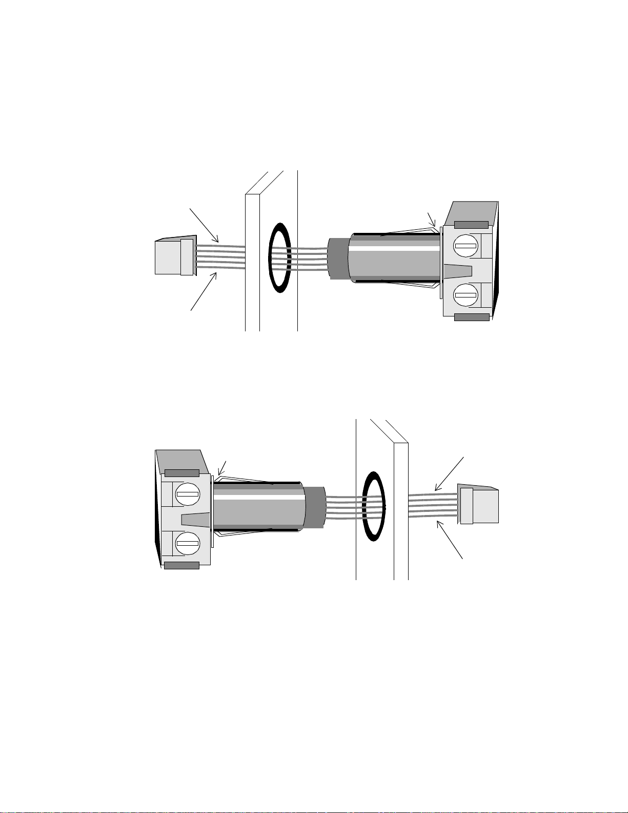
Figure 14 shows how to insert the relay on the LCX 890 or the right side
of the LCX 898.
Figure 14. Inserting a Relay for an Output on LCX 890 or
Right Side of LCX 898
Blue
This Is Where Relay
Latches to Divider
Yellow
Figure 15 shows how to insert the relay on the left side of the LCX 898.
Figure 15. Inserting a Relay for an Output on the Left Side of
the LCX 898
This Is Where Relay
Latches to Divider
Blue
Yellow
To remov e a re la y, grasp the sq ua re end of the relay and ge ntly pull upward and out to release the lower latc h.
36 LCX 890 Installation Guide
Page 47
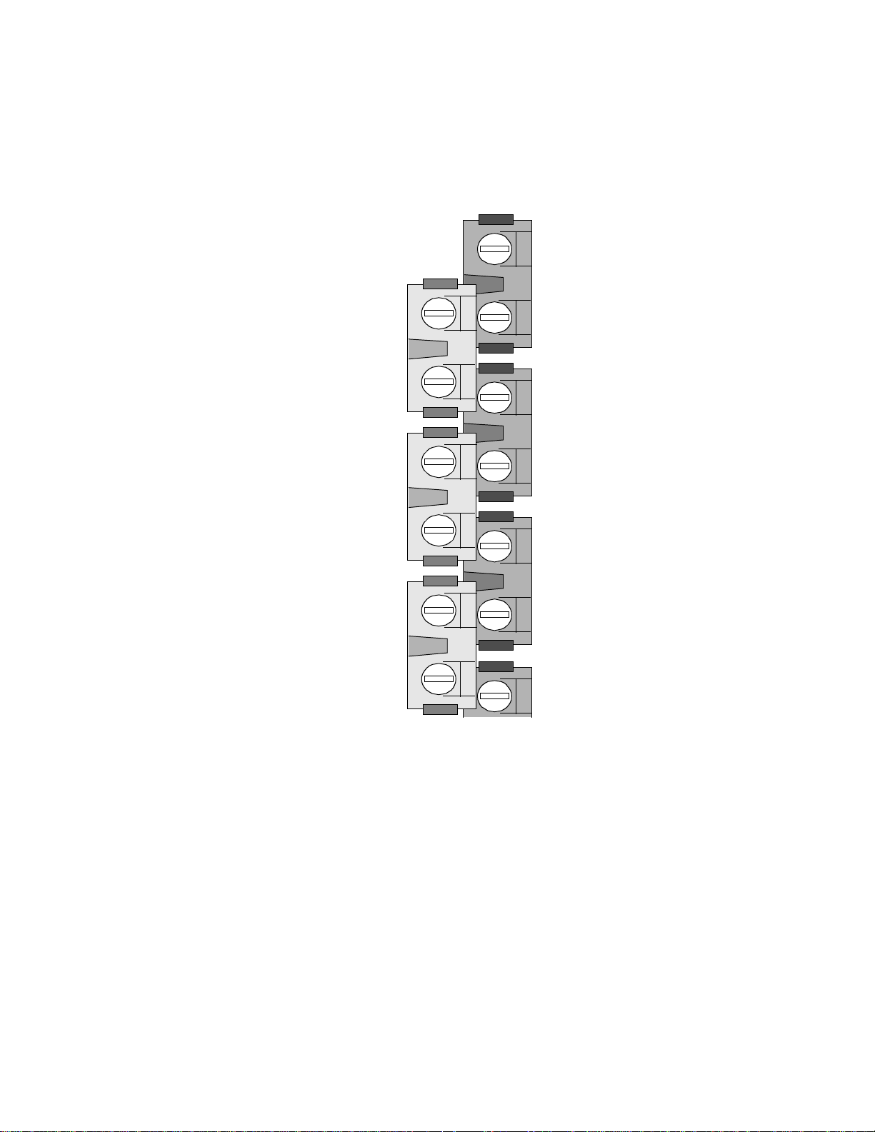
Figure 16 shows how the outputs on the LCX 890 are numbered.
Figure 16. Appearance, Positioning, and Numbering
of Output Relays on LCX 890
Outputs
Numbered
from Top of
Cabinet Down
Output 2
Output 4
Output1
Output 3
Output 6
Output 5
LCX 890 Installation Guide 37
Page 48

Figure 17 shows how the outputs on the LCX 898 are numbered.
Figure 17. Appearance, Positioning, and Numbering of Output
Relays on LCX 898
Outputs
Numbered
from Top of
Cabinet Down
Output1
Output 25
Output 2
Output 3
Output 4
Output 5
Output 6
Output 26
Output 28
Output 30
Wiring the Lights to the Output Relays
Output 27
Output 29
Wire the lig hts as follows:
1. Notice that each relay has two large screws on the top. Loosen the
screws.
2. Now look at the right side of a single output.
As shown in Figure 18, you see four small wire inlets, two under
each large screw.
38 LCX 890 Installation Guide
Page 49

3. Slip the first wire for the light into an inlet under the first screw and
tighten the screw down on it.
Figure 18. Illustration of Wiring Lights to Output Relays
4. Slip the second wire for the light into an inlet under the second screw
and tighten the screw down on it.
5. Repeat the above steps for each output.
Locating/Wiring the Momentary Switches
Each output can be controlled in two possible ways:
• Through the software based on the setting of an input.
• Through a momentary switch (such as a motion detector or push
button) that you wire to the terminals labeled OUT on the other side
of the vertical divider from the output relay. They are each
associated with a particular output and labeled with the output
number.
As shown in Figure 2-1, on the LCX 890 the momentary switches are
all to the left of their corresponding output.
As shown in Figure 2-2, on the LCX 898 the momentary switches are
either to the left or to the right of their corresponding output.
LCX 890 Installation Guide 39
Page 50
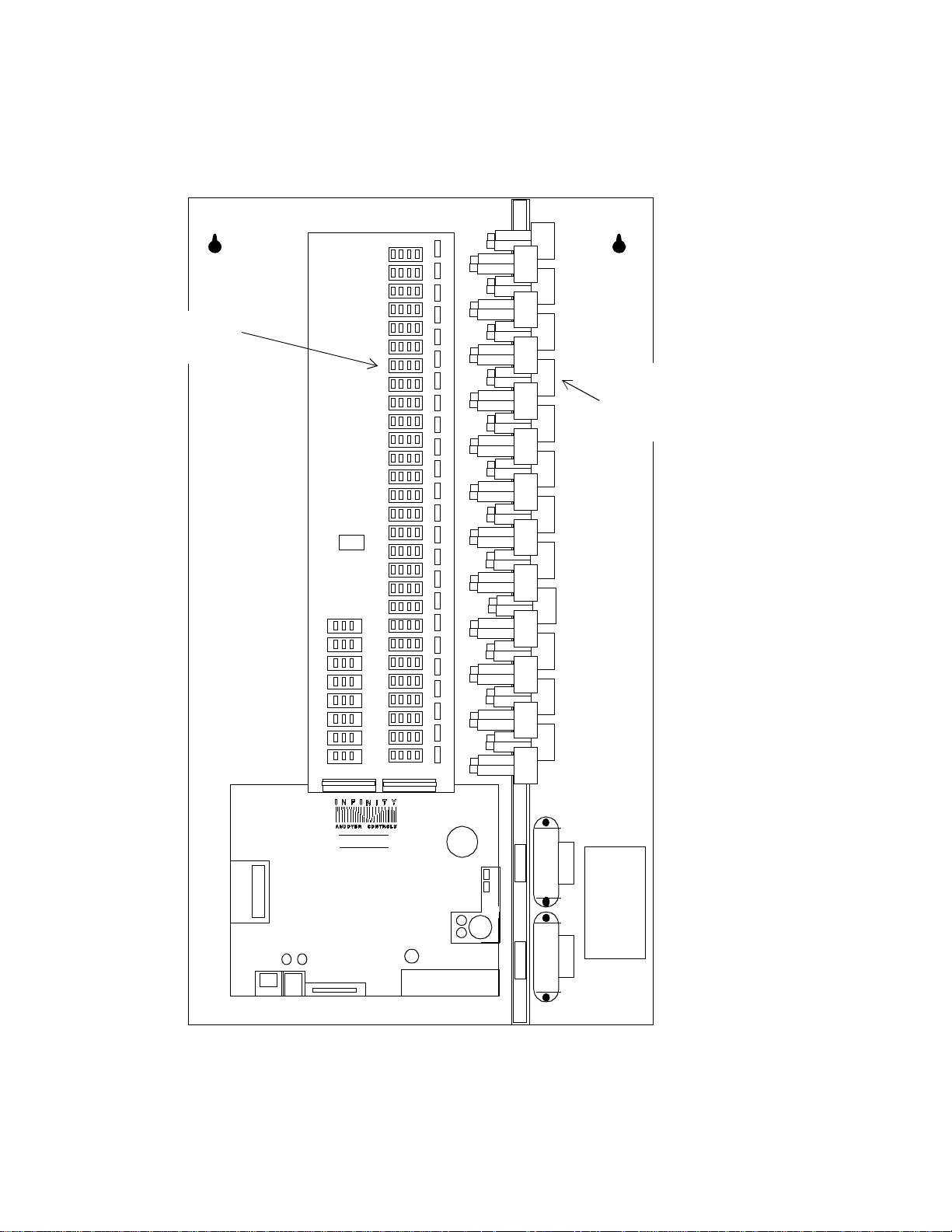
Figure 19. Location of Momentary Switch and Its
Associated Outputs on the LCX 890
Momentary
Switch 7
Output
Relay
Number 7
LCX 890
INPUTS
40 LCX 890 Installation Guide
Page 51

Figure 20. Location of Momentary Switches and Their Associated
LCX 890 Installation Guide 41
Page 52

Outputs on the LCX 898
Output
Relays
Number 5
Momentary
Switch Number 5
Momentary
Switch Number 25
Output
Relay
Number 25
LCX
INPUTS
42 LCX 890 Installation Guide
Page 53

Wiring Four-Wire Momentary Switch
with Status Feedback
Adjacent to each output are four terminal screws that you can wire a
momentary switch to. If you are wiring a four-wire device (one that
gives status feedback), you wire it with up to 1,600 ft (487.7 m) of 20/4
AWG RSWIRE-3 (0.5 mm
2
/4) (standard class) or RSWIRE-3P (f or
plenum applications), as follows:
1. Loosen the four screws you are connecting the input wires to.
2. Slip the black wire under the BLK screw and tighten the s crew down
on it.
3. Slip the red wire under the RED screw and tighten the screw down
on it.
4. Slip the white wire under the WHT screw and tighten the screw
down on it.
5. Slip the yellow wire under the YEL screw and tighten the screw
down on it.
Figure 3 shows a wiring diagram for a four-wire momentar y swit ch .
Figure 21. Wiring Diagram for Four-Wire Momentary Switch
WHT
YEL
BLK (OFF)
RED (ON)
LCX 890 Installation Guide 43
Page 54

Wiring Three-Wire Momentary Switch
with No Status Feedback
Adjacent to each output are four terminal screws that you can wire a
momentary switch to. If you are wiring a three-wire device (one that
does not give status feedback), you wire it with up to 1,600 ft (487.7 m)
of 20/4 AWG (0.5 mm
2
/4) wire, as follows:
1. Loosen the BLK, RED, and WHT screws.
2. Slip the black wire under the BLK screw and tighten the s crew down
on it.
3. Slip the red wire under the RED screw and tighten the screw down
on it.
4. Slip the white wire (or other alternate color) under the WHT screw
and tighten the screw down on it.
5. Ignore the last screw.
Figure 4 shows a wiring diagram for a three-wire mom en tary switch.
Figure 22. Wiring Diagram for Three-Wire Momentary
Switch
WHT
YEL
BLK (OFF)
RED (ON)
You can wire a daylight photosensor the same way, but you can use up
to 500 ft (152.4 m) of 20/3 AWG (0.5 mm
2
/3) RSWIRE-3 or RSWIRE-
3P.
44 LCX 890 Installation Guide
Page 55

Wiring a Single Momentary Switch
to Two Adjacent Outputs on LCX 890 or 898
Adjacent to each output are four terminal screws that you can wire a
momentary swit ch to. Whether you are wiring a four-wire device (one
that gives status feedback) or a three-wire device, you need a couple
of extra jumper wires long enough to provide a bridge between one
momentary switch terminal and the next. One jumper wire is for the
RED terminal a nd one for the BLK. You wire th e two adjace nt outputs
to the one momentary switch. The maximum length of wire you can
use is 750 ft (2 28.6 m) of 20/4 AWG (0.5 mm
switches as follows:
Caution
Do not wire a single switch to more than two outputs.
1. Loosen the four screws you are connecting the input wires to.
2
/4). You wire the
2. Slip the black wire under the BLK screw of the odd numbered
output.
3. Slip the black jumper wire under the BLK screw of the odd
numbered output.
4. Tighten the screw down on both black wires.
5. Slip the other end of the short black wire under the BLK screw of the
even numbered output and tighten the screw down on it.
6. Slip the red wire under the RED screw of the first output.
7. Slip the red jumper wire under the RED screw of the next output.
8. Tighten the screw down on both red wires.
9. Slip the white wire under the WHT screw and tighten the screw
down on it.
LCX 890 Installation Guide 45
Page 56

10. If the device does not provide feedback, skip this step. If the device
does provide feedback, slip the yellow wire under the YEL screw
and tighten the screw down on it.
Figure 5 shows a wiring diagram for a four-wire momentar y swit ch to
control two adjacent outputs. This way you can have a “master” switch
for the two areas.
Since one momentary switch can control a maximum of two output s,
you can have up to two momentary switches/occupancy sensors (four
outputs) wired this way on the entire controller.
Figure 23. Wiring Diagram for Four-Wire Momentary Switch
Controlling Two Adjacent Outputs
First
Output Terminal
Block
Next Adjacent
Output Terminal
Block
WHT
YEL
BLK (OFF)
RED (ON)
46 LCX 890 Installation Guide
Page 57

Wiring a Single Momentary Switch
to Multiple Adjacent Outputs on LCX 898
On an LCX 898 controller you can wire a single momentary switch to
two, three, or four adjacent outputs. Follow the directions for wiring a
single momentary switc h to two ad jac ent outputs to wire the third and
fourth output.
Figure 6 shows a wiring diagram for a four-wire momentar y swit ch to
control three adjacent outputs. This way you can have a “master” switch
for the three areas.
Since one momentary switch can control a maximum of four outputs ,
you can have up to two momentary switches/occupancy sensors (eight
outputs) wired this way on the entire controller.
Figure 24. Wiring Diagram for Four-Wire Momentary Switch
Controlling Three Adjacent Outputs (LCX 898 Only)
First
Output Terminal
Block Block
Second Adjacent
Output Terminal
Third Adjacent
Output Terminal
Block
WHT
YEL
BLK (OFF)
RED (ON)
LCX 890 Installation Guide 47
Page 58

Figure 7 shows a wiring diagram for a four-wire momentar y swit ch to
control four adjacent outputs on an LCX 898. This way you can have a
“master” switch for the four areas.
Figure 25. Wiring Diagram for Four-Wire Momentary Switch
Cont rolling Four Adjacent Outputs (LCX 8 98 Only)
Third Adjacent
Output Terminal
Block
Fourth Adjacent
Output Terminal
Block
WHT
YEL
BLK (OFF)
RED (ON)
First Output
Terminal Block
Second Adjacent
Output Terminal
Block
If you wire momentary switches this way, the length of wire required
varies depending on the number of adjacent outputs you wire to the
switch.
Table 8 shows the correct maximum wire length for two, three, and four
adjacent relays.
Table 8. Lengths of Wire Required for Wiring
Adjacent Outputs to t h e Same Switch
No. Relays Maximum Wire Length
2 750 ft (228.6 m)
3 450 ft (137 m)
4 325 ft (99 m)
48 LCX 890 Installation Guide
Page 59

Wirin g an Occupancy Sensor
as a Momentary Override
Adjacent to each output are four terminal screws that you can wire a
motion sensor to. To provide +24 VAC Rectified to the sensor, you also
connect the blue wire to the terminal for +24 VAC RECT to the left of
output 14. You can use up to 1,000 ft (304.8 m) of 20/4 AWG (0.5 mm
4) ROSWIRE-4 or ROSWIRE-4P.
You wire the motion sensor as follows:
1. Loosen the BLK, RED, and WHT screws on the terminal block you
are connecting the sensor wires to.
2. Loosen the screw labeled BLUE on the +24 VAC RECT terminal
block located to the left of output 14 on the LCX 890 or near the top
center on the LCX 898.
3. Slip the black wire under the BLK screw and tighten the s crew down
2
/
on it.
4. Slip the red wire under the RED screw and tighten the screw down
on it.
5. Slip the white wire under the WHT screw either on the terminal
block for the sensor or on the terminal block for the +24 VAC
RECT. Tighten the screw down on it.
6. Slip the blue wire under the BLUE screw and tighten the screw
down on it.
Note
You can have multiple wires under the same screw or under the other
BLUE screw. However, you may have a maximum of 10 occupancy
sensors wired to both blue terminals on the +24 VAC RECT terminal
block.
LCX 890 Installation Guide 49
Page 60
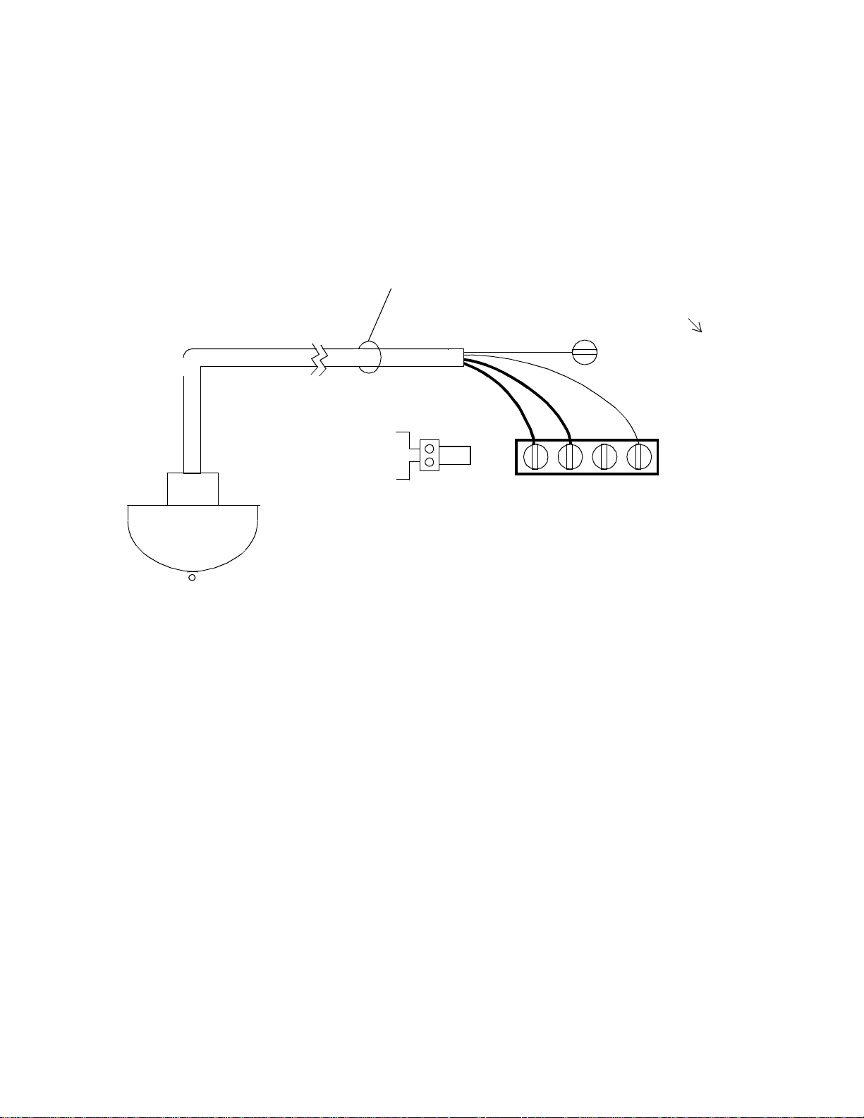
Figure 8 shows a wiring diagram for an occupancy sensor (motion
detector). You may choose to connect the white wire to the WHT screw
near the BLUE one for convenience rather than wiring the white wire
to the WHT terminal on the moment ary ove rr ide terminal block.
Figure 26. Wiring Diagram for Occupancy Sensor
# 20/6
1000ft Maximum
ROSWIRE-6
ROSWIRE-6P
V
. . .
BLK YELRED WHT
(ON) (OFF)
(Refer to earlier illustration
for location on controller.)
BLUE (+24 VAC Rect.)
1st Output
Wirin g an Occupancy Sensor
as a Momentar y Override fo r Tw o Out pu ts
Figure 9 shows a wiring diagram for an occupancy sensor (motion
detector) to control two adjacent outputs. This way you can have one
occupancy sensor for the two areas. You can use up to 500 ft (152.4 m)
of 20/4 AWG (0.5 mm
2
/4)wire.
One occupancy sensor can control a maximum of two outputs. You can
have up to two momentary switches/occupancy sensors (four outputs)
wired this way on the entire controller.
50 LCX 890 Installation Guide
Page 61
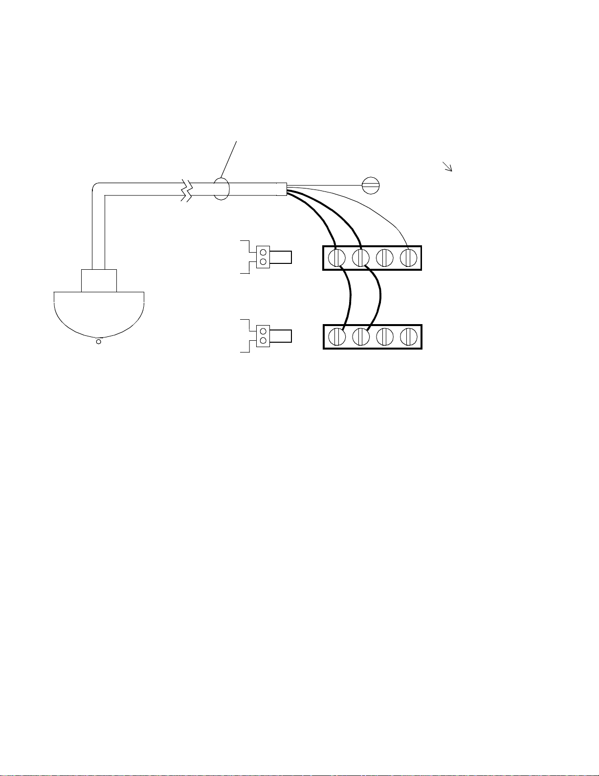
Figure 27. Wiring Diagram for Occupancy Sensor
Controlling Two Adjacent Output
# 20/6
1000ft Maximum
ROSWIRE-6
ROSWIRE-6P
V
. . .
BLK YELRED WHT
(ON) (OFF)
V
. . .
BLK YELRED WHT
(ON) (OFF)
(Refer to earlier illustration
for location on controller.)
BLUE (+24 VAC Rect.)
1st Output
2nd Output
Wirin g an Occupancy Sensor
to Set Lighting to ON/OFF or HI/LO
Figure 10 shows a wiring diagram for an occupancy sensor (motion
detector) to control two separate adjacent outputs. The first output
controls the first two fluorescent tube s and the second the remaining
fluorescent tubes. You ground it only once and connect the blue wire to
the +24 VAC RECT terminal block.
You can use up to 1,000 ft. (304.8 m) of 20/6 AWG (0.5 mm
ROSWIRE-6 or ROSWIRE-6P.
2
/6)
LCX 890 Installation Guide 51
Page 62

Figure 28. Wiring Diagram for Occupancy Sensor
Controlling ON/OFF and HI/LO Outputs
# 20/6
1000ft Maximum
ROSWIRE-6
ROSWIRE-6P
V
(Refer to earlier illustration
for location on controller.)
BLUE (+24 VAC Rect.)
. . .
BLK YELRED WHT
Fluorescent
Tubes
(ON) (OFF)
1st Output
Fluorescent
Tubes
ON
OFF
Controls 1st Output
HI
LO
Controls 2nd Output
Setting the Lighting from Hardware
Rather Th an Software
You either allow the programs to control the lighting or you can allow
a momentary switch (motion sensor, push button, or similar device) to
. . .
2nd Output
BLK YELRED WHT
(ON) (OFF)
control it. You may have both, so that the software may set the lighting,
or the momentary switch ma y set it. You ma y set the lights manually
through the momentary switch, if you choose. But the softw are can
change the hardware setting at any time.
52 LCX 890 Installation Guide
Page 63

The software can read status feedback from the outputs and the indicator light turns on if the output is ON (provided you selected the outputs
that give feedback).
Note
Multiple output terminals on the LCX 898 tha t are wired to the same
switch can be independently software controlled as separate points.
However, multiple output terminals on the LCX 890 that are wired to
the same switch cannot be independently software controlled. They are
considered a single point.
Connecting the EMX 170 or SP 100 Module to the EMX 170 or SP 100 Port
The EMX 170 or SP 100 port at the bottom of the controller just left of
the vertical center is where you can connect a n EMX 170 or SP 100 expansion module. This port has a built-in buffer box for the EMX 170 or
SP 100, so you wire the module directly to the port, without the buffer
box. Refer to the ACC EMX 170 Ins tall ation Guide or the SP 100 In-
stallation Guide for how to install the module.
If you need information on the EMX 170 or SP 100 module, contact
your Andover Controls representative.
LCX 890 Installation Guide 53
Page 64

Powering Up the LCX 890 or 898
Warning
Before powering up the controller, be sure the board is jumpered for the
correct input voltage.
Before you proceed, be sure the following are correct:
1. Be sure you have jumpered the proper input voltage.
2. Be sure the battery is conne cte d.
3. Be sure the AC power is wired properly. Check to be sure you have
connected all three wires.
4. Be sure the controller has a true earth ground.
5. Be sure you have used the proper cables and wires and correct
lengths.
6. Be sure you have properly labeled the tag with the name of the
controller before removing it.
7. Be sure you have properly wired the Infinet cable.
8. Be sure you have properly connected the Infinet cable shields.
If you have completed all previous sections in this manual, you are now
ready to power up the controller.
Turn on the AC power source (or close the power connection) and the
controller starts automatically. The following occurs (also occurs when
you press RESET):
1. The CPU light begins flashing and flashes every .2 sec.
2. The TD light immediately starts flashing (or starts flashing after you
let go of the RESET button) to show data is being transmitted.
54 LCX 890 Installation Guide
Page 65

3. The RD light begins flashing only if data is being received from
other controllers on the network. This may not happen immediately.
4. If the CPU light flashes more slowly than normal, every .4 sec, it
means the CPU has failed a ROM test. If it flashes more quickly than
normal, every .05 sec, i t has f ail ed a RAM test. If the CPU does not
flash at a normal rate, contact your Andover Controls representative
for assistance.
Connecting the Battery
When you have the controller mounted, find the AA battery in the lower
right corner of the lower part of the controller, to t he left of the AC power voltage jumpers. Remove the plastic tab beside the clip on the battery
to activate the battery.
The battery is an 1.8 A-hr 3.6 V primary lithium battery that runs the
real-time clock and maintains RAM and realtime clock when AC power
goes out. The battery is DOT-certified.
Reset Button
The RESET button is the red square button just above the battery on the
far lower right side of the LCX 890 board and on the lower left side of
the LCX 898. You press it to restart the controller without erasing memory. The same events occur as described under Power Up the LCX 890
or 898.
Connecting the Andover Controls Service Tool
The SERVICE POR T on the left side of the bottom of the controll e r,
immediately to the left of the EMX 170 or SP 100 port, is to connect the
Andover Controls Service Tool to an LCX 890. The service tool accesses all LCX 890s and other Infinet controllers on the same network. For
information on availability of the Andover Controls Service Tool, contact your Andover Controls representative.
LCX 890 Installation Guide 55
Page 66

56 LCX 890 Installation Guide
Page 67

Index
A
AC line voltage
choices available 3
setting 22
AC power
connecting 21
AC power connection
location on LCX 890 17
location on LCX 898 19
AC voltage
choices available 3
setting 22
accuracy
wire gauge factors 8
Andover Controls Service Tool
using 54
B
backup power
connecting 54
battery
connecting 54
C
current sensors
wiring 33
D
design
purpose of LCX 890 controllers 1
dimensions
LCX 890 cabinet 3
LCX 890 knockouts 15
LCX 898 cabinet 3
LCX 898 knockouts 16
E
EMX 170 or SP 100 connection
location on LCX 890 17
location on LCX 898 19
EMX 170 or SP 100 modules
connecting 52
EMX 170 or SP 100 port
purpose 52
enclosure
Underwriter Laboratories requirements
6
environments
for operating 6
cabinet
dimensions for LCX 890 3
dimensions for LCX 898 3
knockouts
measurements to LCX 890 15
measurements to LCX 898 16
weight of LCX 890 3
weight of LCX 898 3
cable
for Infinet 4
length 3
circuit requirements for power 3
configuration
planning 12
controllers
purpose of LCX 890 series 1
LCX 890 Installation Guide Index-1
F
four adjacent outputs
wiring to one switch 47
four-wire device
wiring 42
G
ground
correcting 5
inspecting 5
requirements 4
I
Infinet
lightning arrester for 4
Page 68

selecting port for 24
wiring 24
Infinet cable
connecting 23
Infinet cable numbers 4
Infinet connection
location on LCX 890 17
location on LCX 898 19
inputs
circuit specifications 7
digital
requirements 7
EMX 170 8
location on LCX 890 25
location on LCX 898 27
universal
requirements 7
wiring rules 31
J
jumpers
setting for AC voltage 22
K
knockouts in cabinet
measurements on LCX 890 15
measurements on LCX 898 16
use with LCX 890 series 1
momentary switches
location on LCX 890 25, 38
location on LCX 898 27, 38
motion detectors
wiring for hi/lo lighting 50
motion sensors
wiring 48
mounting 13
steps to 13
multiple adjacent outputs
wiring to one switch 46
O
occupancy sensors
wiring 48
wiring for hi/lo lighting 50
wiring one to control two adjacent
outputs 49
outputs
lighting loads allowed 6
numbering on LCX 890 36
numbering on LCX 898 37
relays required 6
wiring rules 31
P
L
lighting outputs
wiring 34
lightning arrester
for Infinet 4
lights
wiring to output relays 38
line voltage
choices available 3
selecting for AC power 22
M
master switch
wiring 45, 46, 47
modules
connecting expansion 52
Index-2 LCX 890 Installation Guide
parts re q ui re d
for installation 13
photosensor
wiring 43
points (see wiring)
port
selecting for Infinet 24
power
battery backup 54
power requirements
circuit 3
power surges
preventing 4
powering up
preparations for 53
programs
vs. hardware control 51
Page 69

R
relays
attaching correctly 35
location on LCX 890 17
location on LCX 898 19
removing 35
repair
packaging required to ship for 13
RESET button 54
resistan ce
across current input 33
RS-485 ports 24
S
screws
mounting 13
sensors (see wiring)
service port
location on LCX 890 17
location on LCX 898 19
purpose of 54
shields
for Infinet cable
connecting 23
required for sensor wire 30
software
vs. hardware control 51
SP 100 or EMX 170 connection
location on LCX 890 17
location on LCX 898 19
SP 100 or EMX 170 modules
connecting 52
SP 100 or EMX 170 port
purpose 52
switches
wiring 31
T
temperatures
for operating 6
thermistors
reducing errors 8
wiring 32
three adjacent outputs
wiring to one switch 46
three-wire device
wiring 43
two adjacent outputs
wiring to one switch 44
U
Underwriter Laboratories
enclosure requirements 6
V
voltage
AC
choices for 3
line
choices for 3
selecting for AC power 22
voltage selection jumpers
location on LCX 890 17
location on LCX 898 19
voltage sensors
wiring 32
W
weight
LCX 890 cabinet 3
LCX 898 cabinet 3
wire
length for adjacent relays 47
wires
gauge for thermistors 8
wiring
AC power connection 21
connecting Infinet cable 23
current sensors 33
four adjacent outputs to one switch 47
four-wire device 42
Infinet 24
inputs 30
lighting outputs 34
master switch 45, 46, 47
motion sensors 48
occupancy sensor to control two adja-
cent outputs 49
occupancy sensors 48
rules for inputs and outputs 31
LCX 890 Installation Guide Index-3
Page 70

switches 31
thermistors 32
three adjacent outputs to one switch
46
three-wire device 43
two adjacent outputs to one switch 44,
46
voltage sensors 32
Index-4 LCX 890 Installation Guide
Page 71

30-3001-285 LCX 890 Series Controller Installation Guide Rev D
 Loading...