

Page 1

Controlling Tomorrow’s World
Infinity Network
Configuration Guide
Downloaded from - http://www.guardianalarms.net
Page 2

Version B
Reproduction or distribution forbidden.
Copyright 1993–1997 by Andover Contro ls .
Subject to change without notice.
Order No. 30-3001-169
Copyright 1997
Andover Controls Corporation
300 Brickstone Sq uare
Andover, Massac husetts 01810
All Rights Reserved.
IMPORTANT NOTICE
This product is subje ct to c hange wit hout notice . Thi s documen t does not co nstit ut e any warranty , e xpress or
implied. Andove r Co ntro ls Corp oration rese rves the rig ht t o alte r capa bi litie s, pe rforma nce, and prese ntati on
of this product at any time.
The following trademarks are used in this manual:
CROSSTALK is a registered trademark of Digital Communications Associates, Inc.
IBM PS/2, PC/AT, and NETBI OS are a reg i stered trademarks of I n ternational Bu siness Machines, Inc.
MS-OS/2 is a trademark of Mic r osoft Corporation.
VT is a trademark of Digital Equipment Corporation.
ARCNET is a trademark of Datapoint Corporation.
Ethernet is a trademark of Xerox Corporation.
ii Andover Controls Corporation
Page 3

Preface
The Infinity Network Configuration Guide presents instructions for planning and in-
stalling an ARCNET- or Ethernet-EnergyNet and multiple Infinets.
It first presents basic information on local area networks (LANs), then introduces
the ARCNET-EnergyNet and how to set up an EnergyNet configuration. Next, it introduces the Ethernet-EnergyNet. It th e n
presents information on Infinets, the smaller networks that branch off of the
EnergyNet.
Finally, it presents how to interpret the LEDs on EnergyLinks and InfiLinks and
how to interpret errors that may be related to t he network on the keypads of 900 or
810 controllers.
At the end is a glossary of LAN terminology that encompasses both ARCNET and
Ethernet concepts.
Infinity Network Configuration Guide iii
Page 4

iv Andover Controls Corporation
Page 5

Chapter 1—Introducing Local Area Networks
What Is a Local Area Network? ......................................................................... 1-2
What Is a Controller? .................................................................................... 1-2
What Is a Workstation? ................................................................................. 1-2
What Is a File Server? ................................................................................... 1-2
What Is a Node? ............................................................................................ 1-2
What Is Network Topology? ............................................................................... 1-3
What Is Bus Topology? ................................................................................1-4
What Is Star Topology? ................................................................................1-4
What Is Ring Topology? ............................................................................... 1-6
What Are the Types of Active Hubs? ................................................................. 1-7
Modular Active Hubs ....................................................................................1-7
Non-modular Active Hubs ............................................................................ 1-7
Active Links .................................................................................................. 1-7
EnergyNet Active Hubs ................................................................................ 1-7
What Types of Cables Form LANs? ................................................................... 1-9
What Is Coaxial Cable? ................................................................................ 1-9
What Is Twisted Pair Cable? ........................................................................ 1-9
What Is Fiber Optic Cable? .......................................................................... 1-9
How Fast Is Data Transmitted? ........................... .......... .......... .......... .........1-10
How Is Data Transmitted on LANs? ................................................................1-11
What Is Token Passing? .............................................................................. 1-11
What Is CSMA/CD? ................................................................................... 1-11
What Are Signaling Methods? ............................................ .......... .......... .... 1-12
What Is Baseband? ...................................................................................... 1-12
What Is Broadband? .................................................................................... 1-13
What Is Carrierband? .................................................................................. 1-13
Advan tages of Ba seband O v er Broadb a n d .......... .................. .....................1-13
How Do You Establish Communication on LANs? .........................................1-14
What Are Software Drivers? ....................................................................... 1-14
What Is a Network Operating System? .......................................................1-14
Contents
Infinity Network Configuration Guide v
Page 6

Chapter 2—Understanding ARCNET-EnergyNet
What Is ARCNET-EnergyNet? .......................................................................... 2-2
What Are the Nodes on ARCNET-EnergyNet? ...........................................2-2
Why Is Token Passing Effective? ................................................................. 2-3
What Is the Hub of ARCNET-EnergyNet? ........................................................ 2-4
What Are Components of EnergyLink 2000? ..............................................2-4
What Is the Active Link/Repeater of ARCNET-EnergyNet? .............................2-7
What Is the ARCNET-EnergyNet Network Interface Card? .............................. 2-8
Chapter 3—Selecting a Cabling Arrangement for ARCNET-EnergyNet
Preparing Coaxial Cables .................................................................................... 3-2
Forming Simple Bus Configurations .................................................................. 3-4
Point-to-Point Connections with Coaxial Cable ...........................................3-4
A Simple Coaxial Cable Bus Topology ........................................................ 3-5
A Coaxial Cable Bus Topology with Workstations ...................................... 3-6
Rules for All Coaxial Cable Bus Topology Networks ................................. 3-7
A Simple Coaxial Cable Star Topology ....................................................... 3-9
Switching Cable Types with EnergyLink 2000s ..............................................3-10
Fiber Optic Bus Topology with EnergyLink 2000s and 2101s ..............................3-10
Rules for Fiber Optic Networks .................................................................. 3-11
Employing EnergyLink 2000s in Complex Configurations ............................. 3-12
Distributed Star Topology with EnergyLink 2000s .................................... 3-12
Expanding the Network with EnergyLink 2000s ....................................... 3-14
Rules When Using EnergyLink 2000s in a Distributed Star Topology ...... 3-14
Cascading EnergyLink 2000s .....................................................................3-15
Extending a Bus with an EnergyLink 2000 ................................................ 3-16
Planning Your Cabling Configuration .............................................................. 3-17
Measuring Cable Lengths ........................................................................... 3-17
Selecting a Cable Type ............................................................................... 3-17
Calculating Total Delays on Long Networks ............................................. 3-18
Summary of Node Connection Rules for All ARCNET-
EnergyNet Topologies ........................................ .......... .......... .......... .......... ...... 3-19
Chapter 4—Understanding Ethernet-EnergyNet
What Is Ethernet-EnergyNet? ............................................................................. 4-2
What Are the Nodes on Ethernet-EnergyNet? .............................................. 4-3
Why Is the CSMA/CD Access Method Effective? ....................................... 4-4
What Is the Hub of Ethernet-EnergyNet? ........................................................... 4-4
What Are Components of EnergyLink 2500? ..............................................4-6
What Is the Ethernet-EnergyNet Network Interface Card? ........................ .. .... .. 4-9
vi Andover Controls Corporation
Page 7

Chapter 5—Selecting a Cabling Arrangement for Ethernet-EnergyNet
Understanding Cable Types ................................................................................ 5-2
Characteristics of Unshielded Twisted Pair Cable .......................................5-2
Characteristics of Thick Coaxial Cable ........................................................ 5-3
Chara c t e r istics o f Th i n n e t Co a x i al Cable .......... .................. ........................ .5-4
Characteristics of Fiber Optic Cable ............................................................. 5-5
Summary of Characteristics of Cable Types ................................................ 5-7
Forming a Simple Point-to-Point Configuration with Twisted Pair Cable .........5-9
Twisted Pair (10Base-T) Ethernet-EnergyNet .............................................. 5-9
Forming a Star Configuration with Twisted Pair Cable ...................................5-11
Forming a Distributed Star Configuration with Twisted Pair Cable ................5-12
Rules for Twisted Pair Networks ................................................................ 5-15
Understanding Thin Coaxial Cable ................................................................... 5-16
Using Coa x i a l Ca b l e s ........... ........ ............... .............. .............. .............. ...... 5-16
Forming a Simple Two-Node Bus with Thin Coaxial Cable
Using T Con n e ct o rs ....... ........ .............. ............... ........ .............. .............. ........ .. 5 - 1 7
Expanding the Simple Bus with Thin Coaxial Cable Using T Connectors ...... 5-20
Lengthening the Thin Coaxial Cable Bus ......................................................... 5-21
Forming a Simple Bus with Thin Coaxial Cable Using Cable Taps ................ 5-23
Forming a Star or Distributed Star Configuration with
Thin Coaxial Cable Using EnergyLink 2500 ................................................... 5-27
EnergyLink 2500 as a Node on Each Bus ................................................ .. 5-31
Rules for Thin Coaxial Cable Distributed Star Topology Networks .......... 5-32
Forming a Two-Node Bus Configuration with Fiber Optic Cable ................... 5-34
Lengthening the Fiber Optic Bus ...................................................................... 5-36
Forming a Star Configuration with Fiber Optic Cable .....................................5-37
Connecting Fiber Optic Cable to EnergyLink 2500 ................................... 5-40
Cascading EnergyLink 2500s Using Fiber Optic Cable ............................. 5-42
Calculat ing Total Si g n al Lo ss .... ............... ........ .............. .............. ........ ...... 5-4 3
Rules for Fiber Optic Networks .................................................................. 5-44
Employing Multiple Cable Types in Long/Complex Networks ..........................5-45
Determining Total Network Length ...................................................................... 5-45
Calculating Total Delay on Long Networks ......................................................... 5-46
Employing Bridges in Long Networks ................................................................. 5-48
Using Local Bridges .............................................................................................. 5-48
Using Remote Bridges ........................................................................................... 5-48
Planning and Setting Up a Long Network ............................................................ 5-50
General Guidelines for Mixed-Cable Distributed Star
Topology Ethernet-EnergyNets ............................................................................. 5-60
Infinity Network Configuration Guide vii
Page 8

Chapter 6—Understanding and Cabling Infinet
What Is Infinet? .................................................................................................. 6-2
What Are the Nodes on Infinet? ................................................................... 6-2
Why Is Token Passing Effective? ................................................................. 6-3
What Is the Twisted Pair Hub of Infinet? ........................................................... 6-4
What Is the Fiber Optic Link of Infinet? ............................................................ 6-5
Forming Twisted Pair Infinet Configurations .....................................................6-6
Extending the Infinet with InfiLink 200 ....................................................... 6-6
Employing InfiLink 200 in Star Configurations ................................................. 6-7
Using Modems with InfiLink 200 ................................................................6-7
Forming Mixed Fiber Optic and Twisted Pair Infinet Configurations ............... 6-9
Extending the Infinet with InfiLink 210 ....................................................... 6-9
Employing InfiLink 210 in an Extended Daisy-Chain ..................................... 6-11
Employing InfiLink 210 in Star Configurations ............................................... 6-12
Limiting Cable Signal Loss Over Fiber Optic Cable ..................................6-15
Planning Your Cabling Configuration .............................................................. 6-16
Infinet Map Drawing Conventions ............................................................. 6-16
Selecting a Cable Type ............................................................................... 6-17
Chapter 7—Interpreting LEDs on EnergyLinks and InfiLinks
Understanding EnergyLink 2000 LEDs ............................................................. 7-2
Interpreting Normal LED Responses ............................................................ 7-3
Interpreting Flashing Lights .......................................................................... 7-3
Responding When +PWR and –PWR LEDs Do Not Light Up .......................... 7-4
Understanding InfiLink 200 LEDs ..................................................................... 7-6
Interpreting Normal LED Responses ............................................................ 7-6
Baud Rate Setting on InfiLink 200 ...............................................................7-7
Checking Fuse on InfiLink 200 ....................................................................7-7
Understanding EnergyLink 2500 LEDs ............................................................. 7-8
Interpreting LED Responses ......................................................................... 7-8
Responding to Excessive Collisions ........................................................... 7-10
Understanding InfiLink 210 LEDs ................................................................... 7-11
Interpreting Normal LED Responses .......................................................... 7-11
Baud Rate Setting on InfiLink 210 .............................................................7-12
Understanding Keypad Errors on 900 or 810 ................................................... 7-13
Error 1 ........ .............. .............. ........ ............... .............. ........ .............. .......... 7-13
Error 2 ........ .............. .............. ........ ............... .............. ........ .............. .......... 7-13
Error 3 ........ .............. .............. ........ ............... .............. ........ .............. .......... 7-13
Error 4 ........ .............. .............. ........ ............... .............. ........ .............. .......... 7-13
Error 5 ........ .............. .............. ........ ............... .............. ........ .............. .......... 7-13
viii Andover Controls Corporation
Page 9

Appendix A—RS-232 Port Pinouts for Controllers and Workstations
Appendix B—Using Thick Coaxial Cable for Ethernet-EnergyNet
Forming a Simple Bus Configuration w ith Thick Coax ial Ca ble ..........................B-2
Using a Transceiver to Tap into Ethernet-EnergyNet ..................................B-4
Tapping Directly into Ethernet-EnergyNet ...................................................B-5
Installing Thick Coaxial Transceivers ..........................................................B-5
Lengthening the Thick Coaxial Cable Backbone ...............................................B-7
Rules for Thick Coaxial Cable Bus Topology Networks . ...... .......... .......... ..B-8
Appendix C—Totaling Propagation Delays for Ethernet-EnergyNet
Appendix D—Mapping Conventions for Andover Networks
ARCNET-EnergyNet Map Drawing Conventions ............................................ D-2
Ethernet-EnergyNet Map Drawing Conventions ............................................... D-4
Glossary—LAN Terminology
Infinity Network Configuration Guide ix
Page 10

x Andover Controls Corporation
Page 11

Chapter 1
Introducing Local Area Networks
Local Area Networks
This chapter covers the following:
• What Is a Local Area Network?
• What Is Network Topology?
• Active Hub Types
• LAN Cable Types
• LAN Data Transmission
• LAN Communications
Infinity Network Configuration Guide 1-1
Page 12

Local Area Networks
What Is a Local Area Network?
A local area network (LAN) is a minimum of two controllers or a controller and a
workstation connected with cabling and running software.
The LAN lets multiple workstations and controllers communicate with (“talk to”)
one another, sharing data, storage space, programs, printers, terminals, other software, and other equipment.
A LAN transmits data much faster than a point-to-point link, such as one over an
RS-232C cable. Where RS-232C usually cannot transmit data faster than 19,200
baud, a LAN can transmit data at the rate of 1 to 10 Mb/sec, hundreds of times
faster.
With a LAN you can also connect many different types of equipment, which is why
a LAN is the perfect method for connecting a building control, process control, or
security system network.
Also, while LANs do not usually extend beyond a mile in length, they can extend
much further than an RS-232C connection.
What Is a Controller?
A controller is a computerized piece of equipment that you use to control an HVAC
system, building access, or process.
What Is a Workstation?
A workstation is a computer complete with a screen and a built-in storage dis k that
you use to access and modify the controller or controllers on your network.
What Is a File Server?
A file server is a workstation that stores files for other workstations or controllers
on the network. You can store all your controllers’ programs on the file server if you
choose.
What Is a Node?
Each workstation, file server, or controller of the LAN is called a “node.”
1-2 Andover Controls Corporation
Page 13
What Is Network Topology?
Network “topology” is the way you arrange the nodes of the network and connect
them with the cables. Three types of topology available on most LANs are as follows:
• Bus Topology
• Star Topology
• Ring Topology
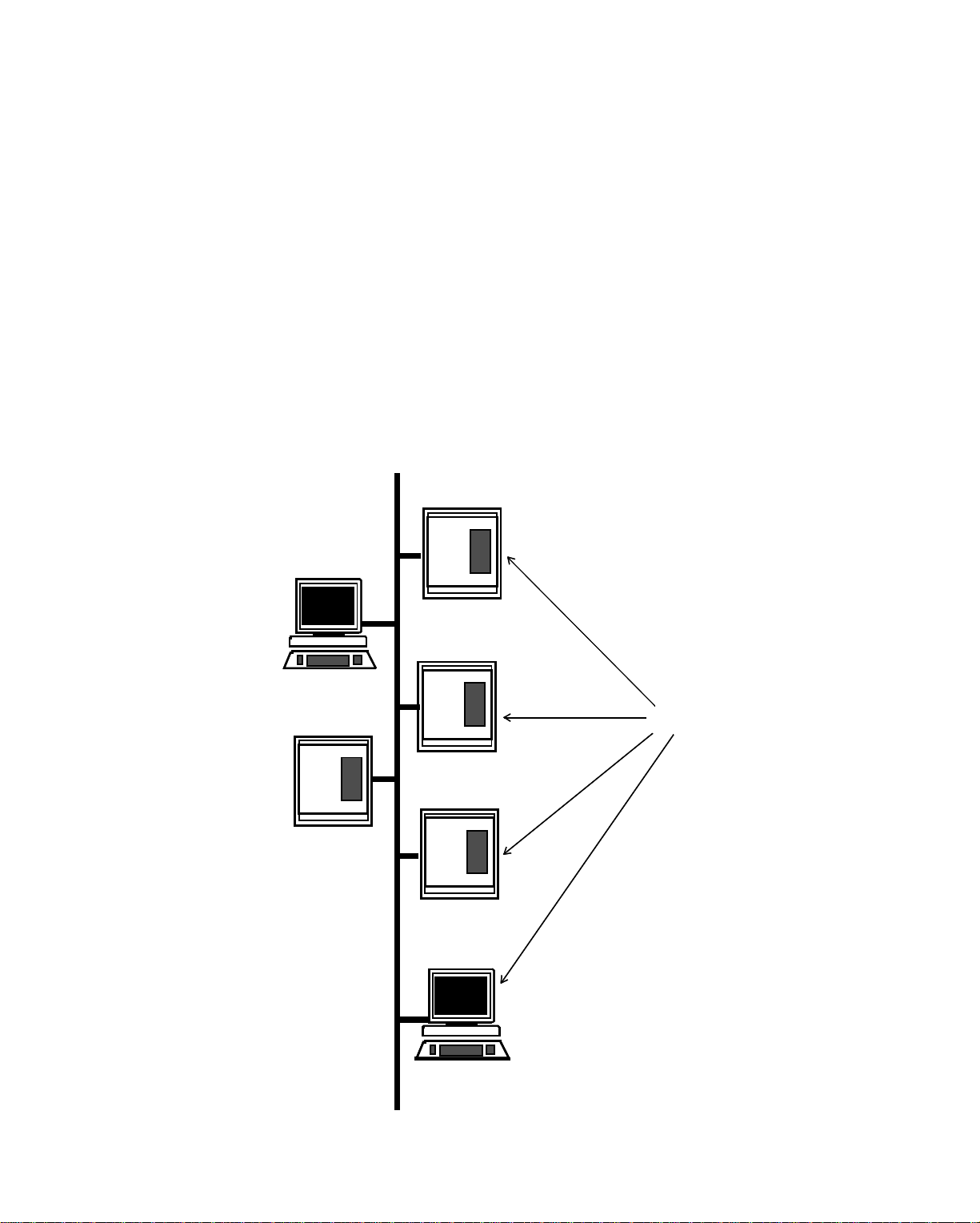
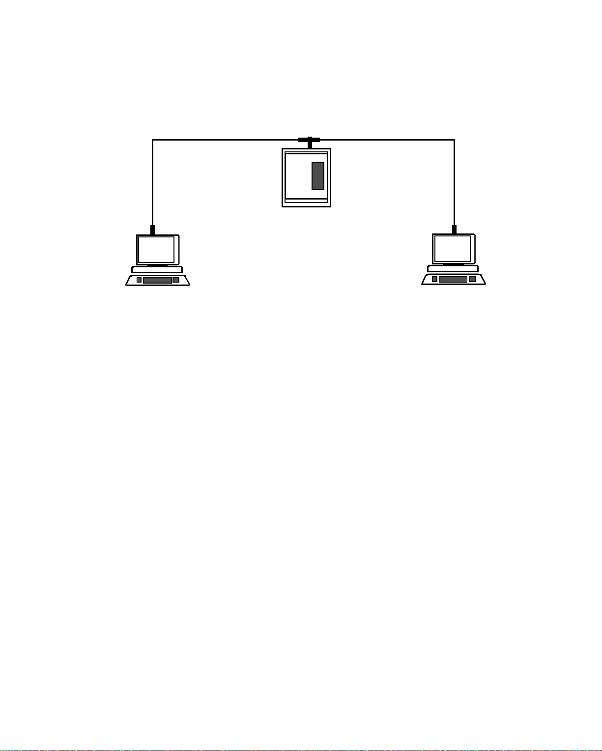
What Is Bus Topology?
Bus topology is an arrangement of nodes on a single cable (also called a “bus”). Each
node is connected to the bus with a connector. A bus sends each message to all nodes
at once. This system of transmission is called a “broadcasting” system.
Figure 1-1. Bu s Topolo gy LAN. This is a “standa rd” Ener gyNet configuration.
LAN
Cable
Local Area Networks
Workstation
Controller
Controller
Nodes
Controller
Controller
Workstation
Infinity Network Configuration Guide 1-3
Page 14
Local Area Networks
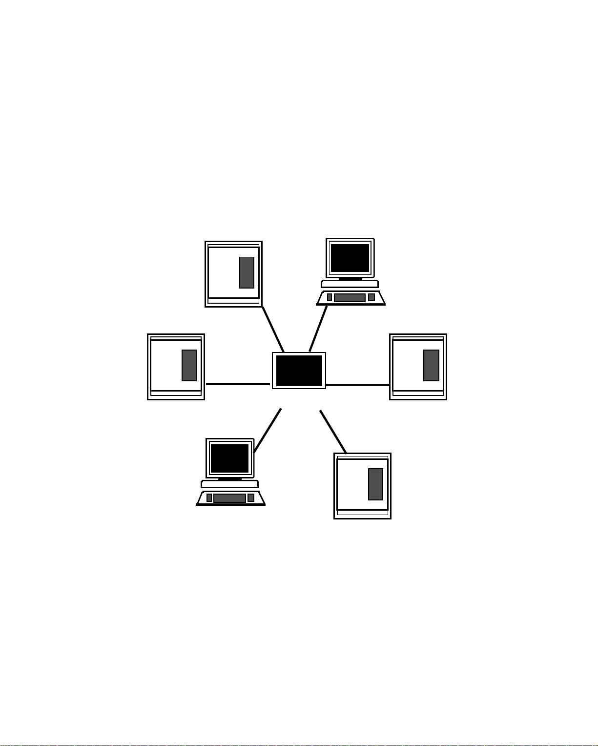
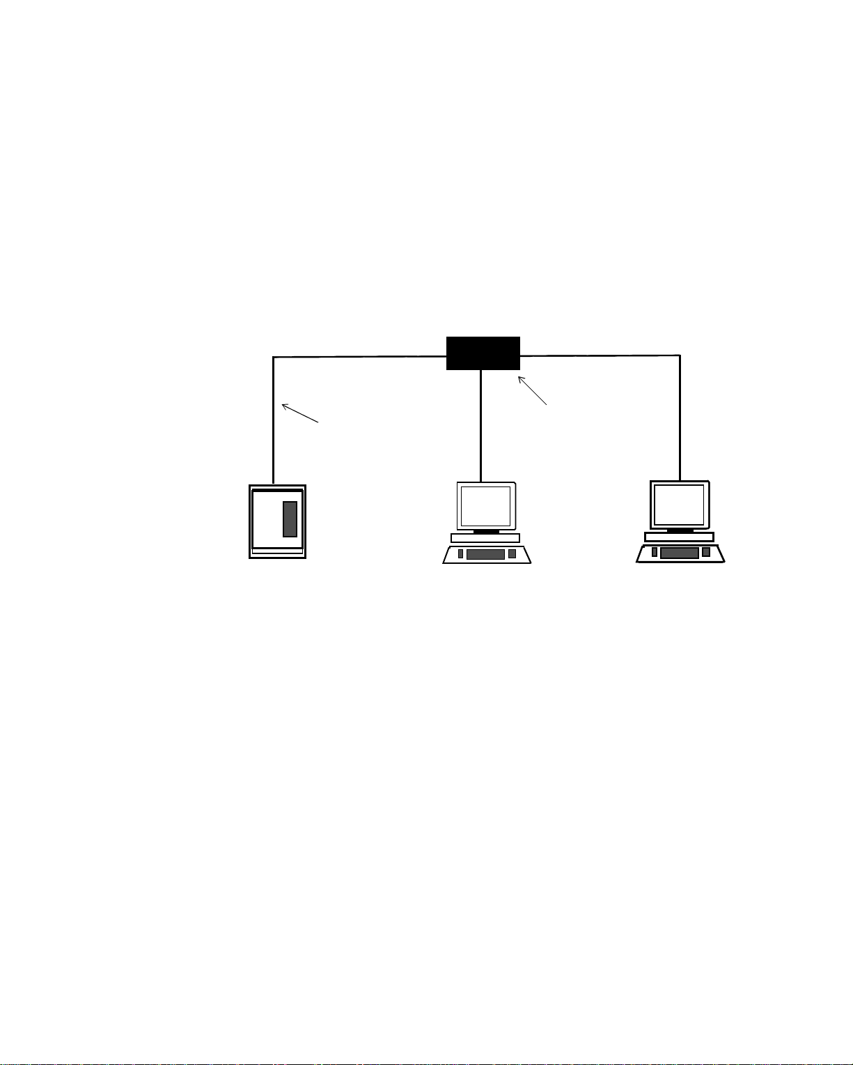
What Is Star Topology?
Star topology is an arrangement where all nodes are connected to a central hub that
is a communications device.
You can add nodes to the network by connecting them to the central hub. After the
LAN becomes active, you can still add another node. You can configure an
EnergyNet in this topology.
Figure 1-2. St ar Topology LAN
Controller
Controller
Workstation
Central Hub
Controller
Workstation
1-4 Andover Controls Corporation
Controller
Page 15

Local Area Networks
What Is a Central Hub?
A central hub in a star topology LAN is either a series of wires connected at one
location (passive hub) or a communications device that transmits data to all nodes
connected to it (active hub).
In simple terms, an active hub requires power to function, whereas a passive hub is
merely a location where multiple wires connect.
An “active hub” is one that acts like a “network repeater,” an electronic device that
retransmits signals that have traveled a long distance. It regenerates signals over
distances of up to 6,561 ft (2,000 m). Active hubs let you isolate networ k nodes so
that if an error occurs on one node or noise interferes with the functioning of one
cable, the rest of the network is minimally affected.
A “passive hub” is one that merely connects several nodes, but does not retransmit
signals. In a passive hub, you must use all ports on the hub, or properly terminate
them.
If one node or one port on a passive hub is not terminated, the entire network is disrupted. Under such a system, you could not isolate a network node. Problems on one
node would reverberate over the network.
So that you can easily remove nodes from the network, Andover
Controls supports only active hubs.
Infinity Network Configuration Guide 1-5
Page 16
Local Area Networks
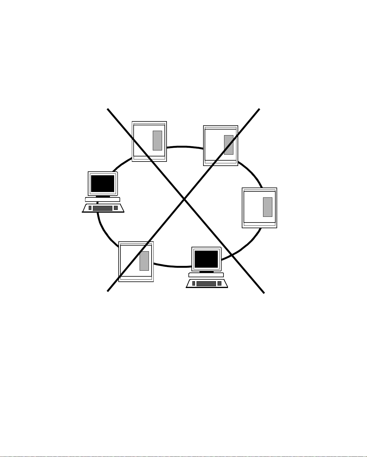
What Is Ring Topology?
Ring topology is an arrangement of nodes in a single continuous loop. Data transmits from node to node in one particular direction. The ring topology is not
supported by EnergyNet because if a single node fails, the entire network fails.
Figure 1-3. Ring Topology LA N
Workstation
Controller
Controller
Controller
Controller
Never attempt to form a ring topology with EnergyNet.
1-6 Andover Controls Corporation
Workstation
Page 17

Active Hubs Types
The following are the most common types of active hubs used in star topology
networks:
• Modular Active Hubs
• Nonmodular Active Hubs
• Active Links
Modular Active Hubs
Also called “variable port hubs,” modular active hubs let you determine how many
ports you want connected to them. You insert a module with the number and type
of ports you want into one of the connectors on the hub.
The modules can be for various types of cables, so you can have fiber optic cable
on one module, coaxial cable on another, and so on—all connected at one hub.
Nonmodular Active Hubs
Local Area Networks
Also called “fixed port hubs,” nonmodular active hubs have a fixed number of
ports, usually eight. To connect more than eight nodes to a network using nonmodular active hubs, you cascade other hubs from a port on one hub to a port on another.
Active Lin ks
You can use an active link as either a repeater or as an interface to switch to another
type of cabling.
When you’ve reached your maximum cable length on a bus, you can use a repeater
to extend the cabling a further distance.
You can use another type of active link to switch from fiber optic cabling to coaxial
cabling or twisted pair cabling. (For more on cabling, see the next section, What
Types of Cables Form LANs?)
EnergyNet Active Hubs
Andover Controls has two active hubs, one for an ARCNET-EnergyNet and the other for an Ethernet-EnergyNet.
EnergyLink 2000 (ARCNET-EnergyNet)
EnergyLink 2000 is the Andover Controls modular active hub for an ARCNET-
EnergyNet networking 9000 and 9500 controllers. It can have up to four modules
and up to 16 ports. You use EnergyLink 2000 as either an active hub or a multiport
cable-switching active link. To use it as a cable-switching active link, you would
replace some of the modules with modules for a different cable type.
Infinity Network Configuration Guide 1-7
Page 18

Local Area Networks
You can also extend the network length with an EnergyLink 2100 as a network repeater. Or you can purchase EnergyLink 2101(for both coaxial and fiber optic
cable) as either a network repeater or an active link for cable switching.
Essentially, EnergyLink 2100 and 2101 are active hubs with only four ports.
You’ll find out more about EnergyLink 2000, EnergyLink 2100, and EnergyLink
2101 in the next chapter.
EnergyLink 2500 (Ethern et-EnergyNet)
EnergyLink 2500 is the Andover Controls modular active hub for an Ethernet-
EnergyNet networking 9200 and 9300 controllers. It can have up to seven modules,
each with a single port. You use EnergyLink 2500 as both an active hub and a multiport cable-switching hub. To use it as a cable-switching hub, you use modules for
various different cable types.
You’ll find out more about EnergyLink 2500 in subsequent chapters.
1-8 Andover Controls Corporation
Page 19
LAN Cable Types
Three types of cable form LAN connections:
• Coaxial
•Twisted Pair
• Fiber Optic
The type of cable you should use often changes with the particular circumstances
of your installation.
What Is Coaxial Cable?
Coaxial cable is a shielded cable and is the most commonly used cabling for LANs
because its shield protects data being transmitted from outside noise. Shielding is
necessary when running cables through equipment rooms where HVAC controllers
reside. It offers the best noise protection at the lowest cost.
What Is Twisted Pair Cable?
Local Area Networks
Twisted pair cable is an unshielded and less expensive cable than coaxial. It is
sometimes the choice in a low noise environment or for use with Ethernet networks.
However, data transmits less reliably over twisted pair cabling and the controller
must often retransmit the data. Although it is perfectly acceptable for EthernetEnergyNet, because it is less reliable than other types of cable, we do not recom-
mend or support twisted pair cabling for ARCNET-EnergyNet.
What Is Fiber Optic Cable?
Fiber optic cable is a shielded cable and o ften used where the LAN requires outdoor
cables. Fiber optic cable is used to protect against lightning damage and other
electrical disturbances. It offers the best noise protection possible, but at a high cost.
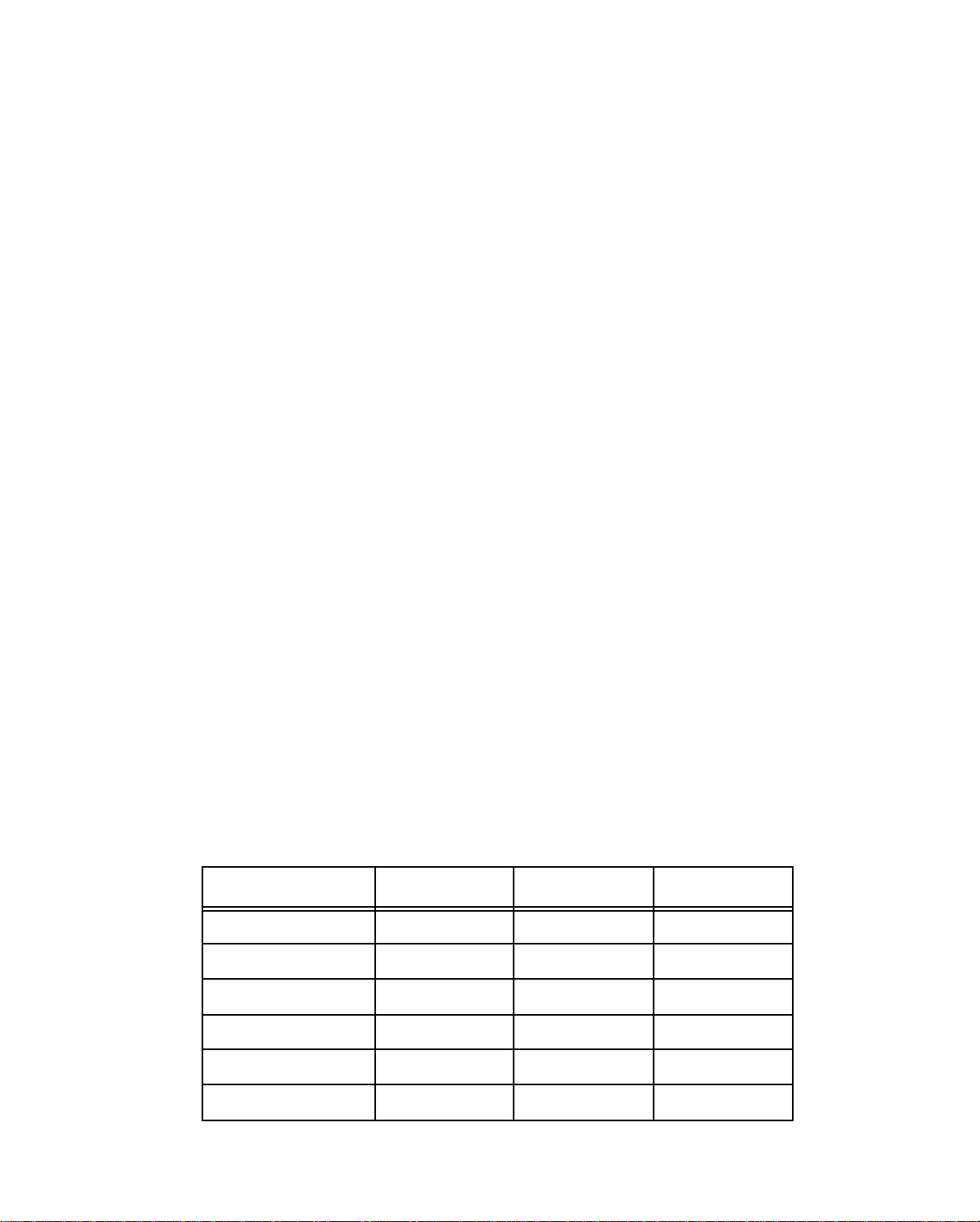
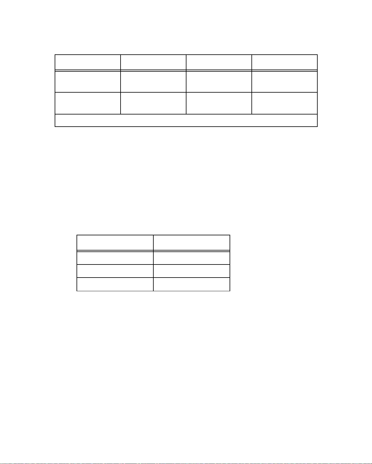
Table 1-1. Compared Characteristics of Coaxial, Fiber Optic, and Twisted Pair
Cabling
Characteristic Coaxial Twisted Pair Fiber Optic
Installed Cost Low Low High
Distance Medium Low High
Topologies Star, Bus Star, Bus Star
Noise Immunity Medium Low High
Outdoor Use Good Poor Excellent
Transmit Speed Medium Low High
Infinity Network Configuration Guide 1-9
Page 20

Local Area Networks
How Fast Is Data Transmitted?
Each of the three types of cables transmits data at different rates:
• Coaxial—Between 1 and 15Mb/sec.
• Twisted Pair—Maximum of 10Mb/sec.
• Fiber Optic—200 Mb/sec.
ARCNET-En ergy Net transmits data at a rate of 2.5Mb/sec. Ethernet-EnergyNet
transmits data at 10 Mb/sec. Although one may appear to have obvious advantage
over the other, you may want to consider some of the other differences between
ARCNET and Ethernet before you choose which one to use in your installation.
1-10 Andover Controls Corporation
Page 21

LAN Data Transmission
Each node on the network accesses the network to transmit and receive data. The
method of access is a set of rules called “protocols.” Two types of protocols used
on LANs are as follows:
• Token Passing
• Carrier-Sense Multiple Access with Collision Detection
(CSMA/CD)
What Is Token Passing?
The token is an electronic signal. Token passing access sends a single token to each
node. The token checks to see if the node has data to transmit. The network passes
the token sequentially, from node to node.
One node receives the token and immediately transmits any data it wants to submit.
The data broadcasts over the network to all other nodes, but only the node that
should receive it responds to it. The network then passes the token along to the next
node where the process repeats. If a node has no data to transmit, it merely passes
the token to the next node.
Local Area Networks
Under the token passing system, each node on the network is an equal. No single
central controller or workstation is required. For this reason, the length of time required to pass a piece of data through the token passing system is always consistent
for a given data size. For example, all messages that are 10 bytes transmit in the
same number of seconds. If the message is longer, it takes more time, shorter, it
takes less time. Heavy network traffic (network activity) does not slow down the
rate data transmits at.
Another advantage to token passing is that should a node fail, the network automatically skips it when passing the token, so that communication continues among all
nodes that are functioning.
Similarly, when you add a new node to the network, the network automatically recognizes that node and passes the token to it at its time in the sequence.
If you cut the network into two parts, each automatically becomes a separate network. Breaking the network becomes a useful tool when troubleshooting.
Both ARCNET-EnergyNet and Infinet are token passing access networks. For the
most efficient token-passing network, Andover recommends you use up to 50 controllers on ARCNET-EnergyNet.
What Is CSMA/CD?
CSMA/CD networks bring messages onto a cable “highway.” Just as on an automobile highway, as long as traffic is normal, cars (nodes) can cut into the flow easily.
Infinity Network Configuration Guide 1-11
Page 22

Local Area Networks
As long as the quantity of traffic is correct for that network highway, information
moves readily along the network paths from node to node.
However, when traffic builds up, as in downtown rush hour, the cars must compete
to be the first in line. The same happens on a CSMA/CD network when the traffic
builds up. Whenever the active node (car) pauses, another node must cut it off and
force its way in to gain access to the network. Thus, when traffic is heavy, CSMA/
CD network nodes compete for access to the network.
In extreme cases, cars become bottlenecked trying to get into the same narrow street
and it becomes impossible to get in. The same can occur on a CSMA/CD network,
so that in excessively heavy network traffic, some messages may not transmit as
quickly as they ought to.
Also, in traffic jams there are sometimes collisions. The same can occur on the network. Network collisions are not fatal, and after they occur, the nodes whose data
collide simply pause and try once again to get onto the network highway.
As you have probably figured out, in heavy traffic, you might have a hard time
estimating the time required to transmit a piece of data over a CSMA/CD access
network. However, on this type of network, the size of the data does not influence
the rate at which it is tr ansmitted. Since network traffic increases as you add nodes
to the network, CSMA/CD access networks are practical as long as the volume of
traffic is not extremely high. The highest traffic networks might achieve better results using token passing.
Ethernet-EnergyNet is a CSMA/CD network that you might choose for EnergyNets
with up to 50 controllers.
One of the best reasons to choose Ethernet, as dis cussed earlier, is speed. At 10 Mb/
sec, Ethernet is considerably faster than an ARCNET operating at 2.5 Mb/sec. In
the right installation, Ethernet is a reasonably priced alternative, because you can
form it using twisted pair cable, the lowest-priced cable available for a LAN.
What Are Signaling Methods?
Three methods of transmitting data on LANs are as follows:
• Baseband
• Broadband
• Carrierband
Each method uses a different type of signal.
What Is Baseband?
Baseband networks transmit either analog or digital signal s over the cabling system
on a single channel. The baseband system encodes digital signals in pulse form be-
1-12 Andover Controls Corporation
Page 23

Local Area Networks
fore entering the cable and decodes them back to their digital for m when they reach
the destination node. EnergyNet is a baseband network.
What Is Broadband?
Broadband networks send data over tot ally separate channels depending on the type
of data it is. They can transmit voice over one channel and video over another, using
digital and analog signals as required.
Before a broadband network sends a signal, it modulates the signal into noninterfering frequencies through a radio frequency (RF) modem. When it the signal
reaches its destination, the broadband demodulates the signals back to their digital
or analog form.
What Is Carrierband?
Carrierband is like a single channel on a broadband network. It requires a modem
and modulates the signal when it sends it out, but does not demodulate the signal
when it reaches its destination.
Advantages of Baseband Over Broadband
Although broadband networks are flexible in transmitting signals, they are difficult
to add a node to. You must reengineer the portion of the broadband network you
want to add the node to.
Baseband networks, on the other hand, are easy to install and add nodes to. You
never need to reengineer the network when adding a node.
Also, baseband networks require only a few components that almost anyone can assemble, while broadband networks require many more components and engineering
expertise to install.
Infinity Network Configuration Guide 1-13
Page 24

Local Area Networks
LAN Communications
After you have connected your network with the appropriate cables, how do you actually get the controllers and workstations talking? You use two types of software:
• Software Drivers
• Network Operating System
What Are Software Drivers?
Software drivers provide the instructions to transmit data over the network. The
ARCNET-En ergy Net software driver is a NETBIOS c ompatible driver. The Ethernet-EnergyNet software driver is a NETBEUI compatible driver. NETBIOS and
NETBEUI are standard drivers used by common network operating systems.
What Is a Network Operating System?
The network operating system is the software that lets workstations and controllers
on a network share hardware resources, such as disk drives and printers.
Two types of environments exist in the operating s ystem: shared resource and peerto-peer.
A shared resource environment has a file server that distributes data as required to
the nodes on the network. The software on each node accepts requests from the users and sends those requests to the file server whenever required. EnergyNet has the
Microsoft OS/2 LAN Manager for its network operating system whenever workstations are on the network.
When two controllers communicate with each other (without a workstation), they
use the peer-to-peer environment. They do not have a central file server. Instead,
nodes access files through Andover network protocols. Protocols are rules that govern communication on the network.
Andover Controls combines shared resources and peer-to-peer communication
forming a unique environment for building control. Andover Controls equipment
uses shared resources for graphics and long term storage and peer-to-peer for controller to controller data exchange.
1-14 Andover Controls Corporation
Page 25

Chapter 2
Understanding ARCNET-EnergyNet
ARCNET-EnergyNet
This chapter covers the following:
• What Is ARCNET-EnergyNet?
• What Is the Hub of ARCNET-EnergyNet?
• What Is the Active Link/Repeater of ARCNET-EnergyNet?
• What Is the ARCNET-EnergyNet Network Interface Card?
Infinity Network Configuration Guide 2-1
Page 26

ARCNET-EnergyNet
What Is ARCNET-EnergyNet?
The ARCNET EnergyNet1 is a high-performance, token-passing local area network
(LAN) of Andover Controls controllers and workstations and the network software
that makes them communicate. Over a million ARCNET nodes are currently installed worldwide.
The ARCNET-EnergyNet network drivers are NETBIOS. The workstations on the
network communicate through the operating system, the Microsoft OS/2 LAN
Manager software. The LAN Manager uses a shared resource environment, with a
file server serving all other workstations on the network.
ARCNET-En ergy Net has a minimum of two controllers or a controller and a workstation, usually connected with RG-62/u coaxial cable. It can connect up to 254
nodes. Data transmits over the ARCNET-EnergyNet at a rate of 2.5 Mb/sec when
you use coaxial cable. Depending on your particular installation, you may want to
use fiber optic combined with coaxial cabling instead. You can use both types to
construct ARCNET-EnergyNet.
Although ARCNET-EnergyNet has a token-passing data access syst em, it has a
combination bus and star topology called “distributed star” topology.
ARCNET-EnergyNet is a baseband network, connected by up to 4 miles (6.4 km)
of coaxial cabling. The number of nodes on the network inf luences the length of c able that connects the entire network, but the maximum distance you can have
between two nodes is 1,428 ft (435 m) with coaxial cabling and 6,000 ft (1,828.8
m) with fiber optic cabling.
As with any baseband network, ARCNET-EnergyNet is easy to install. It requires
only cabling and interface modules. You may also use EnergyLink 2100 or 2101,
electronic repeaters, to extend the amount of cabling beyond the limit for a given
number of nodes. EnergyLink 2100 (or 2101) amplifies and retransmits signals so
that they can travel further on the network.
What Are the Nodes o n ARCNET-Ener gyNet?
The two types of nodes on ARCNET-EnergyNet are controllers and workstations.
The 9000 and 9500 controllers are ARCNET-EnergyNet controllers. (Other con-
trollers, called Infinet controllers, are not directly connected to the ARCNETEnergyNet. See Chapter 6 for more o n the Infinet controller network.) Each 9000
controller counts as a single node on ARCNET-EnergyNet. You give an ID to each
controller by setting a DIP switch inside it. How to set the EnergyNet ID is in the
installation guide for the 9000 controllers.
1. ARCNETControl s s o ftwa re.
2-2 Andover Controls Corporation
EnergyNet
is ARCNET, developed by Datapoint Corporation, combined with Andover
Page 27

ARCNET-EnergyNet
The 8000 workstation is a user-friendly IBM PC workstation with detailed color
graphics that connects to the network. The 8000 workstation can also be a file server, storing files for other workstations on the ARCNET-EnergyNet. You can
program all your controllers from a single workstation that operates as a file server,
if you choose. Each workstation or server counts as a single node on ARCNETEnergyNet. You give each workstation an ID by setting a switch on its network interface card. How to set the switch is detailed in the ins tructions you received with
the card.
Each active hub is also considered a node on the network. You set the ID of the hub
as described in the EnergyLink Installation Guide.
Why Is Token Passing Effective?
Token passing, as discussed in Chapter 1, is one of the best methods for real-time
building control systems because data of a particular length is always transmitted in
a given amount of time. Token passing allows ARCNET-EnergyNet to not only accept data of any length, but also automatically acknowledge receiving data and
automatically check for errors, giving all nodes equal access to the network.
ARCNET-EnergyNet handles all network control so that 9000 and 8000 software
can ignore network control and operate more efficiently.
If you remove a controller or workstation from the network, the ARCNETEnergyNet automatically reconfigures itself and continues operating without
interruption.
Infinity Network Configuration Guide 2-3
Page 28
ARCNET-EnergyNet
What Is the Hub of ARCNET-EnergyNet?
The hub of ARCNET-EnergyNet is EnergyLink 2000.
EnergyLink 2000 is a 16-port modular active hub that retransmits messages to the
spokes (arms) of the hub just the way an electronic network repeater would.
The hub has four modules, with four ports each. You can have coaxial, fiber optic,
or mixed coaxial and fiber optic modules on the EnergyLink 2000. Because you can
interchange modules, you can have EnergyLink 2000 function as a cable switching
center, if you connect the appropriate modules to it.
You do not have to terminate unused ports on the EnergyLink 2000. Because the
ports are always properly terminated, you can later disconnect one node from the
network without interrupting the building control system.
When EnergyLink 2000 connects several nodes, it controls communication on two
fronts:
• Between the nodes in the star.
• Between the nodes in the star and the other hubs on the network.
Because each node has a separate transceiver, you do not encounter problems with
cable loading.
See also the EnergyLink 2000 Installation Guide supplied with the unit.
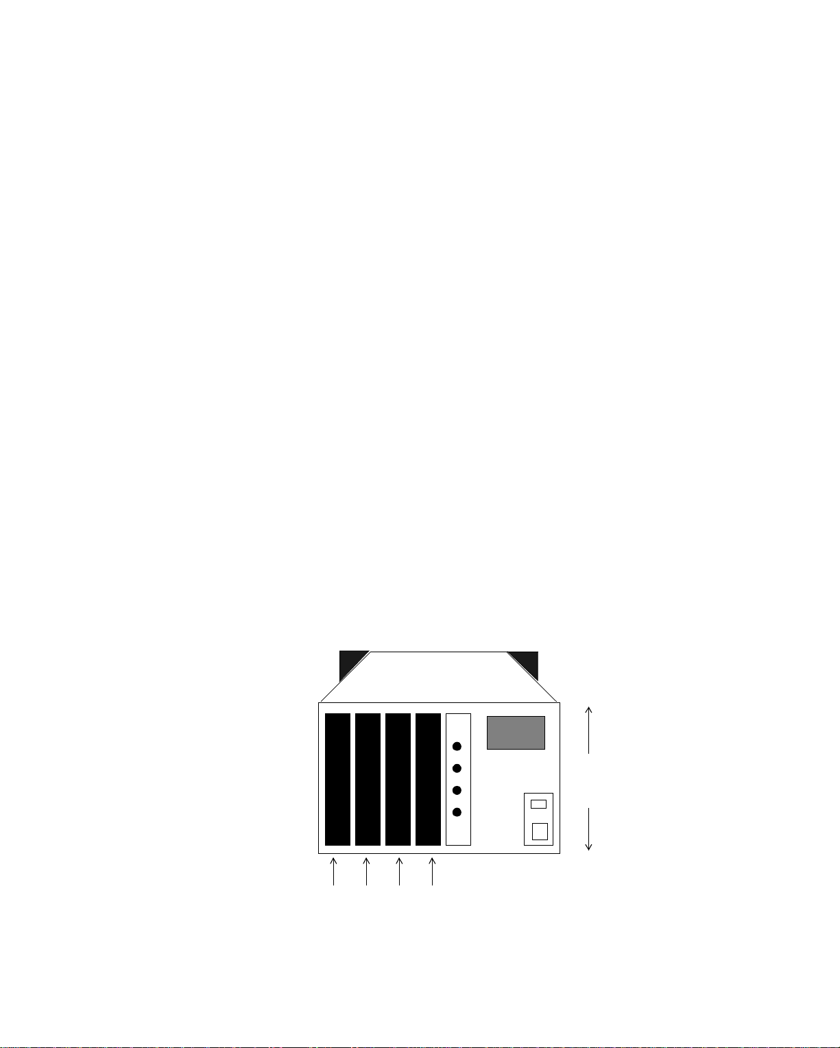
What Are Components of EnergyLink 2000?
Figure 2-1. EnergyLink 2000 Before Modules are Connected
6 inches
(15.24 cm)
Where Four
Modules Connect
2-4 Andover Controls Corporation
Page 29
ARCNET-EnergyNet
You can mount the EnergyLink 2000 inside another NEMA enclosure or mount it
on a wall as is.
When you first see EnergyLink 2000, you see four slots. You insert a module with
four ports in each those slots. Then you have 16 ports in all. If you need only 12
ports, you need only use three modules.
When you order EnergyLink 2000, you order at least one module with either all four
ports coaxial, all four ports fiber optic, or two ports coaxial and two ports fiber optic. To order EnergyLink 2000 and the modules, use the following Andover
Controls model numbers:
• Andover Controls Model # 2000—16 port hub (115/230V 50/60 Hz)
• Andover Controls Model # 2001— Module with 4 coaxial ports
• Andover Controls Model # 2002— Module with 2 coaxial ports,
2 fiber optic ports
• Andover Controls Model # 2003—Module with 4 fiber optic ports
You can order a maximum of four modules per hub.
Figure 2-1 shows ports on the modules. Each coaxial port connects to the male end
of a BNC connector and each fiber optic port connects to the end of a fiber optic
cable.
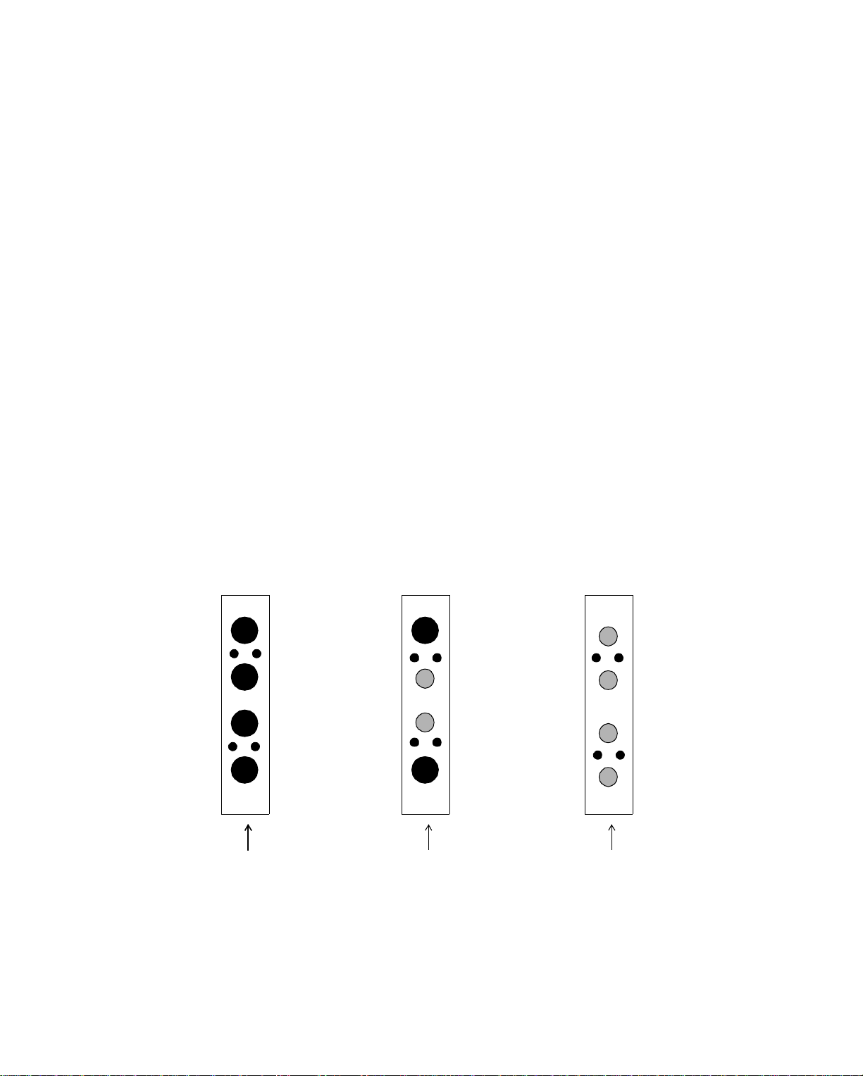
Figure 2-2. Ports for Different Cables on Various Modules
Four Coaxial Ports
on Module
Two Coaxial,
Two Fiber Opt ic
Four Fiber Optic
Ports on Module
Ports on Module
Although the hub behaves the way a repeater would, you would not want to use it
as a repeater, because you would not take advantage of the 16 ports. Andover Controls has a repeater with four coaxial ports called EnergyLink 2100. If you want to
Infinity Network Configuration Guide 2-5
Page 30

ARCNET-EnergyNet
switch from coaxial to fiber optic cable, you can pur chase the EnergyLink 2101 active link, with two coaxial and two fiber optic cable ports.
How Do You Read EnergyLink 2000’s LEDs?
EnergyLink 2000 also has LED lights on top that correspond to each module. The
LEDs to the right of the rightmost module are for timing and reconfiguration. The
timing light indicates ARCNET-EnergyNet is receiving and transmitting signals.
The reconfiguration light turns on to indi cate that the network has been configured.
The network reconfigures itself when you remove a node.
The activity LEDs on the rest of the modules blink to indicate that ports on that
module are receiving and transmitting data. See Chapter 7 or the EnergyLink Instal-
lation Guide for more details on how to interpret the LEDs.
2-6 Andover Controls Corporation
Page 31

ARCNET-EnergyNet
What Is the Active Link/Repeater of ARCNETEnergyNet?
A small-scale version of the EnergyLink 2000, the EnergyLink 2100 has a single
module with four coaxial ports and acts as a network repeater. You can also use it
as a hub for three or four nodes that all require coaxial cable.
EnergyLink 2101 has a single module with two coaxial and two fiber optic ports.
You often use it as a cable-switching active link. It can also be a network repeater
for either a coaxial or fiber optic cable bus.
To order EnergyLink 2100 or 2101, use the following Andover Controls model
numbers:
• Andover Controls Model # 2100—4 coaxial port active link/repeater
• Andover Controls Model # 2101—2 coaxial and 2 fiber optic port active link
In some instances, you can interchange EnergyLink 2100 with
EnergyLink 2000. It is, basically, a hub with fewer ports.
In other instances, such as when you switch cable types, you can interchange
EnergyLink 2000 with EnergyLink 2101. Both can also be the central hub of a star
with mixed cable types, but the EnergyLink 2101 would form only a three- or fourarm star.
Infinity Network Configuration Guide 2-7
Page 32

ARCNET-EnergyNet
What Is the ARCNET-EnergyNet Network Interf ace Card?
ARCNET-EnergyNet supports two network interface cards that let you connect
workstations to the network:
• Andover Controls Model # 2020 for AT bus systems (IBM PC and Compaq
computers)
• Andover Controls Model # 2040 for IBM PS/2 bus systems
See your Andover Controls Representative for specific hardware supported.
Because the network interface card is considered a node on the
ARCNET-EnergyNet, it must have an EnergyNet ID, just as all other nodes on the
network have.
You select the EnergyNet ID by setting a DIP switch inside the controller cabinet.
You can assign each node an ID from 1 to 254. EnergyNet ID number 0 is reserved
by ARCNET-EnergyNet to broadcast a message to all nodes. Otherwise, you can
use any of the other ID numbers for any node or network interface card.
To assign the AT bus (Compaq) card an ID, set a DIP switch on it following the
instructions provided with the card. To assign the PS/2 card an ID, you set it through
the software. Details on how to set the PS/2 card ID are included in the computer’s
documentation for the Reference disk.
EnergyNet IDs for 9000 controllers range from 1 to 223 and for 8000 workstation
range from 224 to 254.
When passing the token from node to node, ARCNET-EnergyNet starts with the
node with the lowest EnergyNet ID number and proceeds to the one with the highest. When it reaches the highest ID number, ARCNET-EnergyNet returns to the
lowest, proceeding in a cycle called a “logical ring.”
As shown in the figure on the next page, the logical r ing is based on the EnergyNet
ID number, not on the physical placement of the nodes.
2-8 Andover Controls Corporation
Page 33
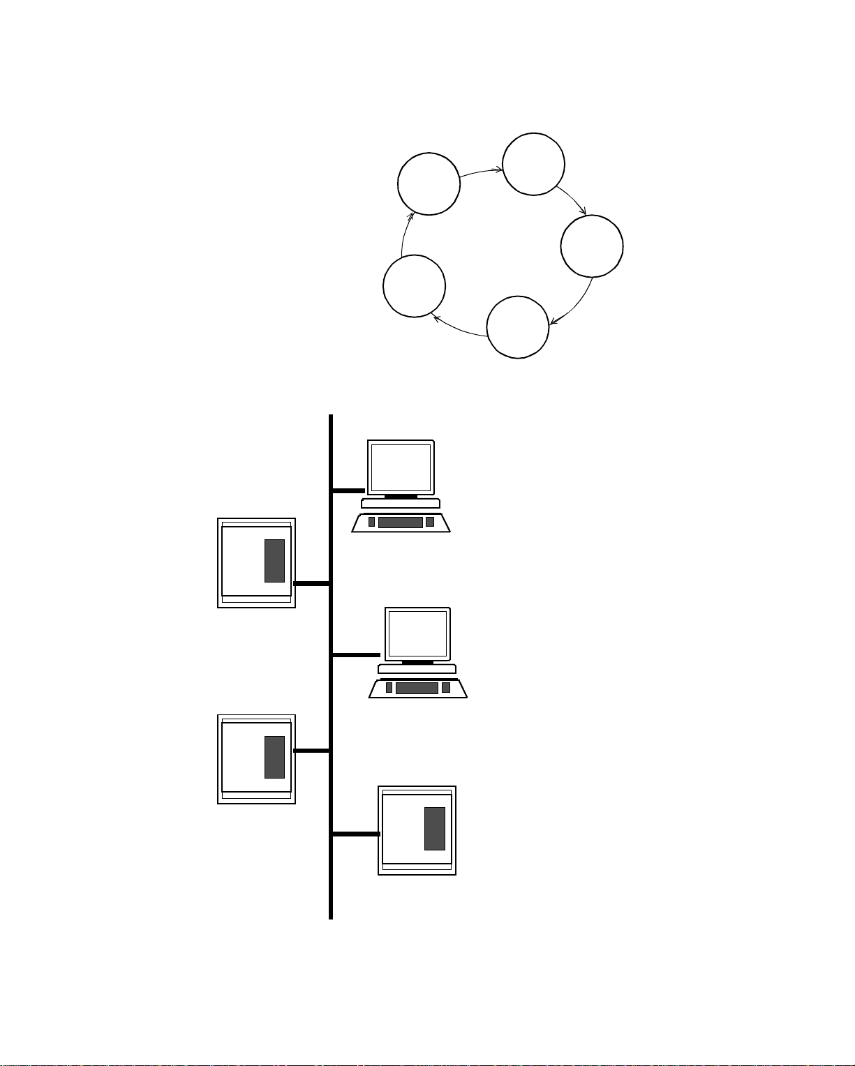
Figure 2-3. Logical Ring vs. Physical Layout of Nodes
86
1
ARCNET-EnergyNet
Logical Ring
230
Layout of Nodes on Network
230
8000 Workstation
1
9000
Controller
224
126
224
126
9000
Controller
8000 Workstation
86
9000 Contro lle r
Infinity Network Configuration Guide 2-9
Page 34

ARCNET-EnergyNet
2-10 Andover Controls Corporation
Page 35

Cabling Configuration for ARCNET
Chapter 3
Selecting a Cabling Arrangement for ARCNETEnergyNet
We recommend you read all of the information in this chapter before designing your
own ARCNET-EnergyNet configuration. This chapter covers the following:
• Preparing Coaxial Cables
• Forming Simple Bus Configurations
• Switching Cable Types with EnergyLink 2000s
• Employing EnergyLink 2000s in Complex Configurations
• Planning Your Cabling Configuration
• Summary of Node Connection Rules for All Topologies
Infinity Network Configuration Guide 3-1
Page 36

Cabling Configuration for ARCNET
Preparing Coaxial Cables
No matter which type of network topology you use, each length of coaxial cable
connecting to a controller, workstation, EnergyLink 2000, EnergyLink 2100, or
EnergyLink 2101 must have a BNC male connector at both ends. If the cables are
not already premade, you prepare them by attaching the male connectors.
If possible, you should use premade cables, because when creating your own, you
could inadvertently cut a single wire too short, or twist or break a wire. If a single
wire is not properly connected, you later have communications problems that may
be difficult to diagnose.
Figure 3-1 shows a single piece of prepared coaxial ARCNET-EnergyNet cable.
Each piece of coaxial cable from male connector to male connector must be at least
6 ft (1.82 m) long.
Figure 3-1. ARCNET-EnergyNet Coaxial Cable
6 ft. (1.82 m)
minimum
Male Connectors
on either end of Coaxial Cable
—Each connects directly to
controllers at ends of bus
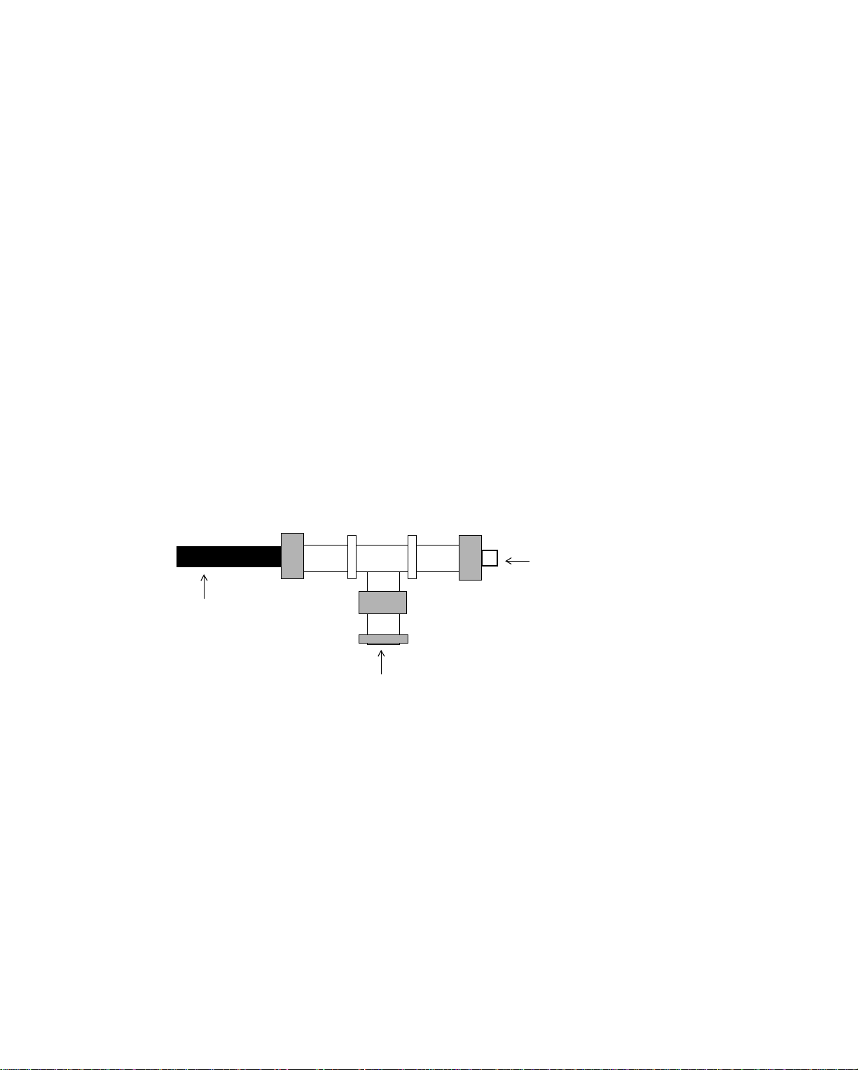
Figure 3-2 shows the ARCNET-EnergyNet coaxial T connector (Andover Controls
Model # 2070). This connector is required on most (but not all) controllers on a bus.
(More about buses later.)
Figure 3-2. ARCNET-EnergyNet Coaxial T Connector
Coaxial Cable
Coaxial Cable
Connects to coaxial
connector on a controller
not
at end of bus
3-2 Andover Controls Corporation
Page 37

Cabling Configuration for ARCNET
Figure 3-3 shows the coaxial ARCNET-EnergyNet cable co nnecting to t h e T
connector.
Figure 3-3. ARCNET-EnergyNet Coaxial Cable Connections
Connects to Controller
or Workstation
Male BNC
Connector
Male BNC
Connector
BNC T
Connector
Prepared Cables
Connect to Another Node
and Connects directly to controller at end of Bus
Plug the end of the coaxial T connector for the ARCNET-Energy Ne t c ab le into the
ARCNET-EnergyNet connector just above and to the left of the uppermost RS-485
port on the controller board. (Or directly connect the male BNC connector to the
controller if it is at the end of a bus. See the next section for details on buses.)
Every T connector on the network has three ends. The bottom of the T always connects to the coaxial connector on a controller or workstation on the network. The
two sides of the T connector always connect to a coaxial cable.
Infinity Network Configuration Guide 3-3
Page 38

Cabling Configuration for ARCNET
Forming Simple Bus Configurations
Let’s look at a series of simple configurations first.
Point-to-Point Connections with Coaxial Cable
Suppose you want to connect two 8000 workstations, two 9000 controllers, or one
of each. To connect two nodes point-to-point, you must first terminate the nodes.
Each controller is terminated when you purchase it, with a built-in removable 93 Ω
terminator.
Figure 3-4 shows the built-in terminator in upper left corner of the printed circuit
board inside the 9000 controller.
Figure 3-4 . Built-i n Te rminator on 90 00 C ont roller
Fuse for
2000
Built-in Removable
93 Ω Terminator
EnergyLink
Power
Capacitor
•
•
EnergyLink 200 0
Connection
Power
in Pico Fuse Socket
Coaxial Cable
Connection
Each workstation can be terminated with a jumper on its network interface card. To
form the two-node network, terminate the workstation (see the card instructions)
and connect the two nodes. Connect the male BNC connector on the coaxial cable
directly to the workstation’s network interface card.
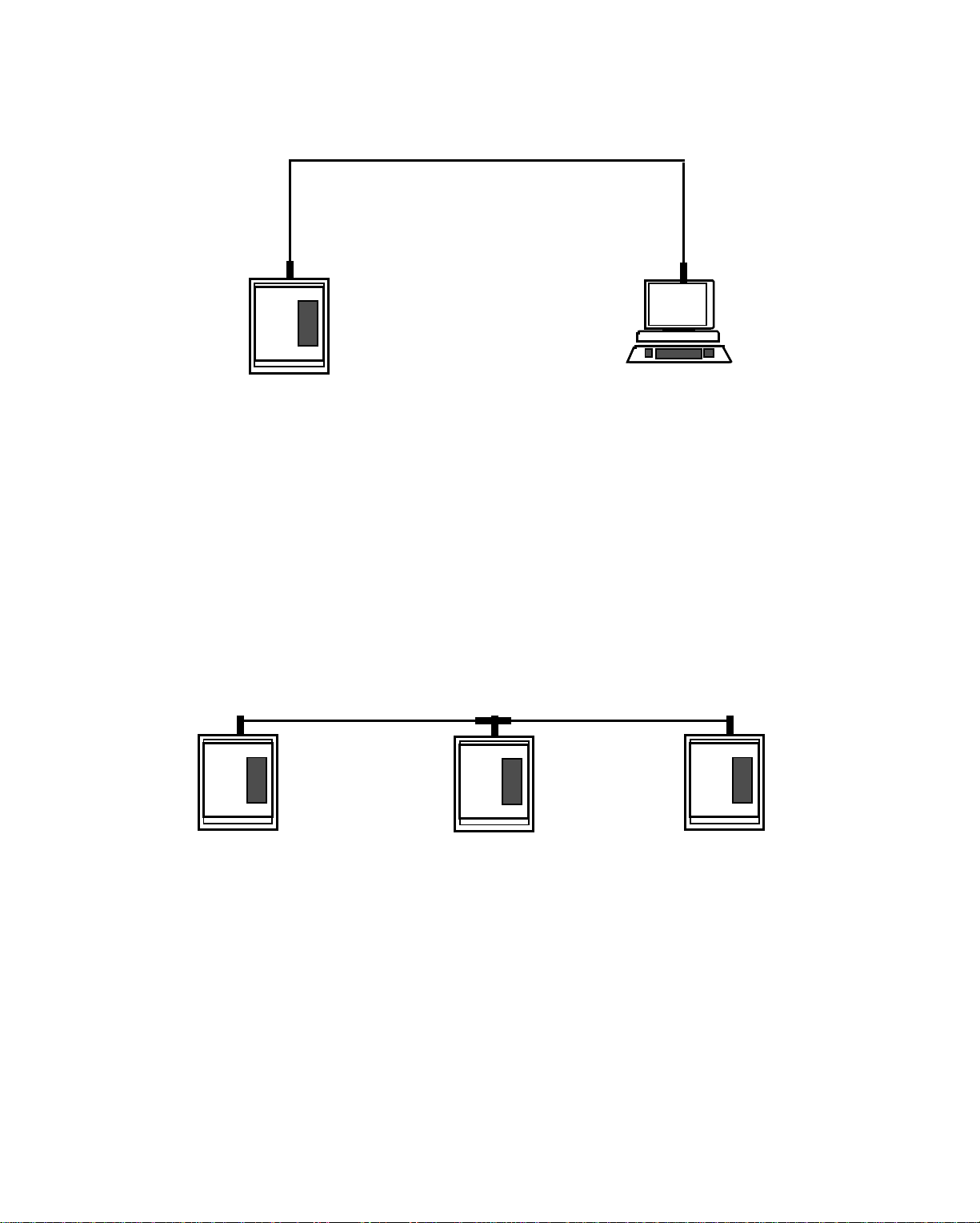
Figure 3-5 shows a simple point-to-point connection with no hub in the simplest bus
topology.
3-4 Andover Controls Corporation
Page 39
Cabling Configuration for ARCNET
Figure 3-5. Two-Node Point-to-Point Connection
Workstation
Has Jumpered
Interface Card
Terminator
Controller
Has Built-in
Terminator
9000
Controller
8000
Workstation
A Simple Coaxial Cable Bus Topology
If you want to join three nodes, you could join three 9000 controllers in a bus topology, as long as you leave the terminator in tact at both ends of the bus and remove
it from the node(s) in between.
The bui lt- in 93 Ω term inat or i s in a pi co fuse so cke t. When yo u do not want to terminate a controller, remove the terminator from the socket.
Figure 3-6 shows three controllers in a bus topology network.
Figure 3-6. Three -N o de Bus To pology with Ter m in at ors
9000
Controller
9000
Control le r
9000
Control le r
(Terminator
Removed)
With coaxial cabling, you can connect up to 19 contr ollers ( 9000s ) on one continuous bus, as long as you terminate the network properly on both ends and keep the
length requirements.
Rule for Using Connectors and Terminators on Coaxial ARCNET-EnergyNet:
Always direct connect controllers at the end of a bus with a male connector and
leave the terminator on the board in tact.
Always connect controllers in the middle of a bus with a coaxial T connector and
remove the terminator from the board.
Infinity Network Configuration Guide 3-5
Page 40
Cabling Configuration for ARCNET
A Coaxial Cable Bus Topology with Workstations
You can also have a bus topology network with an 8000 workstation on either end.
In this configuration, whether or not you need a terminator on the end of the bus
depends on the kind of network interface card each workstation has:
• With the AT card, you can terminate the connection by jumpering the appropri-
ate terminal on the card to form a terminator right there on the card. (See the card
instructions.)
• With the PS/2 card, you must terminate the bus by connecting a
93 Ω terminator to the open end of the T connector.
If you have all IBM or Compaq workstations on an AT bus, you can select those
that terminate the network and jumper their cards. When you do this, connect the
male BNC connector on the coaxial cable directly to the network interface card.
You terminate the workstation with a PS/2 card by attaching a 93 Ω connector to
the open end of the coaxial T connector.
Figure 3-7 shows the terminated T connector on a PS/2 card.
Figure 3-7. Coaxial T Connector Terminated for PS/2 Card
93 Ω Terminator
connects to a coaxial
T connector to
Coaxial Cable
terminate PS/2 card
Connects to coaxial
connect or on con troller
3-6 Andover Controls Corporation
Page 41
Cabling Configuration for ARCNET
Figure 3-8 shows how two workstations with jumpered terminators form the ends
of a three-node bus topology network.
Figure 3-8. Three-Node Bus Topology with Jumpered Termi nato rs on Workstati ons
9000
Controller
8000
Workstation
8000
Workstation
with Jumpered
with Jumpered
Terminator
Terminator
Rules for All Coaxial Cable Bus Topology Networks
You must adhere to the following when creating an all coaxial cable bus topology
ARCNET-En ergy Net:
• Terminate the bus at both ends by leaving the 93 Ω terminator in tact on the
controllers. You can terminate a workstation by setting the jumper on the
workstation network interface card.
• Connect male connectors directly to the network interface card on workstations
without a T connector if terminated on a jumper on the card.
• Use only Andover Controls T connectors (Andover Controls Model # 2070).
• Keep the length of a bus connection at a maximum of 1,000 ft
(304.8 m) for eight nodes and decrease or increase it proportionally for more or
fewer nodes (see table on next page).
• Keep the maximum number of nodes to 19 with a length of the bus cable limited
to 200 ft (60.96 m).
• Be sure each piece of cable from node to node is a minimum of 6 ft (1.82 m)
long.
Infinity Network Configuration Guide 3-7
Page 42

Cabling Configuration for ARCNET
We do not recommend using more than 19 nodes on a single bus.
Table 3-1 shows the amount of cable allowed for from two to 19 nodes. Remember,
the general rule is eight nodes per 1,000 ft (304.8 m) of cable.
Table 3-1. ARCNET-EnergyNet Bus Cable Length vs. Number of Nodes
Nodes Maximum Cable Length
2 1,428 ft (435.25 m)
3 1,356 ft (413.30 m)
4 1,285 ft (391.66 m)
5 1,213 ft (369.72 m)
6 1.141 ft (347.77 m)
7 1,070 ft (326.13 m)
8 998 ft (304.19 m)
9 926 ft (282.24 m)
10 855 ft (260.60 m)
11 783 ft (238.65 m)
12 711 ft (216.71 m)
13 640 ft (195.07 m)
14 568 ft (173.12 m)
15 496 ft (151.18 m)
16 425 ft (129.54 m)
17 353 ft (107.59 m)
18 281 ft (85.64 m)
19 210 ft (64 m)
You can extend the length of cable for a particular number of nodes using
EnergyLink 2100.
3-8 Andover Controls Corporation
Page 43
Cabling Configuration for ARCNET
n
A Simple Coaxial Cable Star Topology
If you try to form a three-node network by tying the three nodes together at one
point in a star topology, you add a passive hub or either an EnergyLink 2100 or an
EnergyLink 2000.
Figure 3-9 shows a three-node star topology with a hub. In this configuration, where
you use an EnergyLink 2000 or EnergyLink 2100, you must terminate all
workstations or controllers, because the hub acts as a node at the end of a bus. So
all nodes on this network must have terminators.
Figure 3-9. Three-Node Star Topology wi th a Hub
Maximum
Length Bus
Cable Is
200 ft.
(50.96 m)
for Passive
Each Arm
Off the Hub
Is Like a Bus
EnergyLink
2000
2100
Hub or
Active
Link
ub, 1428 ft.
(435.25 m)
Energy-
for
Link 2000
Energy-
or
Link 2100
9000
Controller
8000
Workstation
Workstatio
8000
Because after three nodes, the passive hub becomes extremely unreliable, Andover
does not recommend you use passive hubs.
Also, since the maximum length cables you should use with a passive hub is
between 100 and 200 ft, using a passive hub would restrict your network. If you use
an EnergyLink 2000 instead, you can extend cable 1428 ft (435.25 m) between
nodes. Remember, if you remove a node from a passive hub, the entire network is
disrupted. So, even in a simple star topology where long cabling is not required, we
recommend EnergyLink 2000s or EnergyLink 2100s for the greatest flexibil ity and
reliability. See the section called Employing EnergyLink 2000s in Complex
Configurations.
Infinity Network Configuration Guide 3-9
Page 44

Cabling Configuration for ARCNET
Switching Cable Types with EnergyLink 2000s
Fiber Optic Bus Topology with EnergyLink 2000s and 2101s
Andover Controls recommends you use glass fiber optic cable for running ARCNET-EnergyNet cable outdoors or through a high-noise environment. You may
choose to form an entire bus of fiber optic cable or merely extend a coaxial network
between buildings with fiber optic cable.
How do you connect fiber optic cable to a controller with coaxial connector on its
board? You use EnergyLink 2000 with modules for both coaxial and fiber optic ca-
ble. Or you use an EnergyLink 2101 because it has two coaxial and two fiber optic
ports. You’ll need one EnergyLink 2000 or EnergyLink 2101 for each controller or
workstation on the fiber optic bus. Connect each as follows:
1. Connect one end of a prepared coaxial cable to a coaxial port on the EnergyLink
2000 or EnergyLink 2101.
2. Connect the other end of the prepared coaxial cable to one side of the T
connector on the controller or to the network interface card of a workstation.
Be sure to run a minimum of 6 ft (1.82 m) of coaxial cable from the controller
or workstation to the EnergyLink 2101 (or EnergyLink 2000).
3. Be sure the built-in terminator is in place on each controller and that each
workstat ion’s netwo rk interfac e c ard is jumpe red to termina te it.
4. Run glass fiber optic cable from a port on one EnergyLink 2101
(or EnergyLink 2000) to a port on the next EnergyLink 2101 (or EnergyLink
2000).
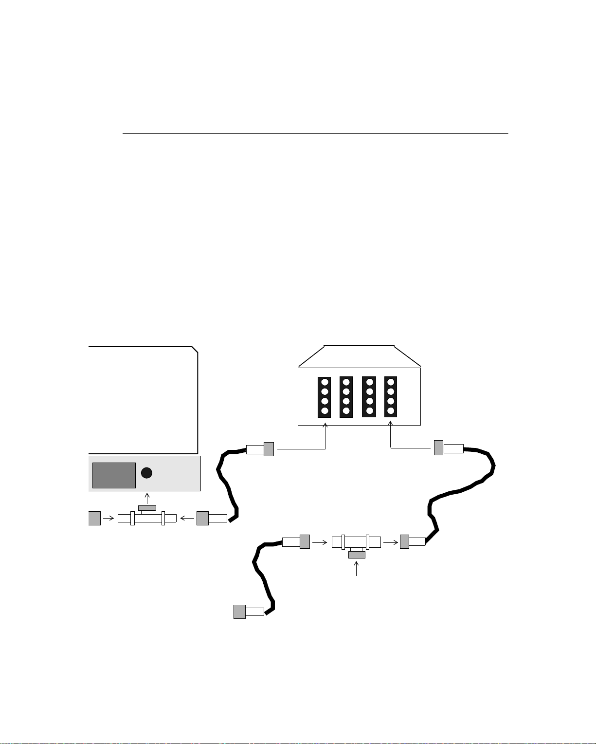
Figure 3-10 shows a three-node fiber optic bus topology with EnergyLink 2101s.
Figure 3-10 . Three-Node Fiber Opt ic Bus Top ology
Fiber Optic Cable
EnergyLink 2101
s
Minimum 6 ft. (1.82 m)
Coaxial Cable
9000
Controller
3-10 Andover Controls Corporation
8000
Workstation
8000
Workstatio n
Page 45

Cabling Configuration for ARCNET
Rules for Fiber Opt ic N et wo rks
If you choose to employ fiber optic cable be sure you meet the following criteria:
• Follow National Electrical Code (NEC) restrictions if running cable through
HVAC plenums or ducts. You can use Teflon-coated cable in this situation if
the code requires it.
• Be sure the amount of cable between nodes does not exceed
6,000 ft. (1,828.8 m) (See also the table at the end of this chapter.)
• If cable between nodes must exceed 6,000 ft (1,828.8 m), then use EnergyLink
2101 as a repeater. See the section called Extending a Bus with an EnergyLink
2000 later in this chapter.
• Be sure the overall network does not exceed 20,000 ft (6,096 m).
An EnergyLink 2000 is somewha t like a network r epeater because it retransmits s ignals, so you can also use it to extend the length of the fiber optic bus.
You can also use other EnergyLink 2000s to expand the number of nodes on the network. For more information on using EnergyLink 2000s, see the section called
Employing EnergyLink 2000s in Complex Configurations.
Infinity Network Configuration Guide 3-11
Page 46

Cabling Configuration for ARCNET
Employing EnergyLink 2000s in Complex Configurations
Distributed Star Topology with En ergyLink 2000s
The most flexible way to add 8000 workstations or 9000 controllers to ARCNET-
EnergyNet is through an EnergyLink 2000 or similar model.
EnergyLink 2000s allow you to expand your network much further than buses or
passive hubs would allow.
You use several EnergyLink 2000s for groups of nodes and cascade the hubs togeth-
er, forming “buses” between them. Each single arm of the star is also a bus and can
have up to seven nodes on 1,000 ft (304.8 m) of coaxial cable (EnergyLink 2000 is
the eighth node). This combination of bus and star topology for ARCNETEnergyNet is called a “distributed star” topology.
Figure 3-11 shows an all coaxial cable distributed star topology.
Figure 3-11. Coaxial Distribut ed S ta r Topology Netw or k
EnergyLink 2000
s
Coaxial Buses
Cascading
EnergyLink
2000
Each Arm ("Spoke")
EnergyLink 2000
of
s
EnergyLink
2000
Is Like a Bus
Each Arm ("Spoke")
EnergyLink 200 0
of
Can Have up to Seven
Nodes on 1,000 ft.
(304.8 m) (Eight including
EnergyLink 2000
the
3-12 Andover Controls Corporation
)
Page 47

Cabling Configuration for ARCNET
Figure 3-12 shows a fiber optic cable distributed star topology.
Figure 3-12. Fiber Optic Distributed Star Topology Network
EnergyLink 2000
s
Fiber Optic
Buses
Cascading
EnergyLink
2000
s
Each Arm ("Spoke")
EnergyLink 200 0
of
Is Like a Bus
Each Spoke
Is Coaxial
Cable and Can Have
up to Seven Nodes on
1,000 ft. (304.8 m) of Cable
(Eight Nodes including the EnergyLink 2000)
EnergyLink
2000
Distributed star topology is the most common configuration of ARCNETEnergyNet. You can form it with a variety of types of cabling, from coaxial cabling
to fiber optic to twisted pair. Coaxial cabling is still the one that connects all nodes
to the network, but you may switch to other types of cabling using EnergyLink 2000
or EnergyLink 2101 and following the criteria under the rules for each type of network given earlier in this chapter.
Infinity Network Configuration Guide 3-13
Page 48

Cabling Configuration for ARCNET
Expanding the Network with EnergyLink 2000s
A single EnergyLink 2000 can have up to 16 ports. Either a single node or a bus of
up to seven nodes (the EnergyLink 2000 becomes the eighth) can connect to a single
port. The prepared coaxial cable male BNC connector attaches to a standard port
without a T connector or terminator.
The other models of EnergyLink 2000 offer up to four ports. You can use them as
hubs if you plan to form smaller stars.
The EnergyLink 2000s offers the following expansion options:
• You can have more than four nodes without losing reliability.
• You need not terminate unused ports.
• A fault on one cable or node does not affect other cables or nodes on the
network.
• You can add or remove nodes without reconfiguring the network.
• You can use a cable length of up to 1,000 ft (304.8 m) between low impedance
nodes.
• You can have a coaxial bus off each EnergyLink port with up to seven nodes on
it. Since EnergyLink 2000 (or other models of EnergyLink 2000) is considered
a node of each bus it connects to, you can have only seven more nodes on 1, 000
ft (304.8 m) of cable.
• The total cable cascading EnergyLink 2000s (or other models of EnergyLink
2000) can be up to 4 miles (6.4 km) long.
• You can cascade up to eight EnergyLink 2000s.
• You can easily switch cable types at any time by inserting a module with the
number and type of ports you want into one of the connectors on the EnergyLink
2000. Or you can switch cable types with EnergyLink 2101.
• You can have multiple modules for various cable types, so you can have fiber
optic cable on one module, coaxial cable on another, and so on—all connected
at one EnergyLink 2000.
Each port on the EnergyLink 2000 has a transceiver that matches that of the controller or the network interface card of the workstation.
Rules When Using EnergyLink 2000s in a Distributed Star Topology
When using a distributed star topology, you must adhere to the following:
• For all types of cabling, you must terminate every controller or workstation at
the end of a spoke on a hub—either by leaving the
93 Ω terminator in the controller in tact or by jumpering the card on the
workstation.
3-14 Andover Controls Corporation
Page 49

Cabling Configuration for ARCNET
• All of the restrictions given earlier for each type of cabling also apply in the
distributed star configuration.
• Only one end of a bus may connect to an EnergyLink 2000.
• For every 1,000 ft (304.8 m) of cabling with seven nodes on the s ame bus, you
must install one EnergyLink 2000 as a repeater.
Cascading EnergyLink 2000s
You can cascade EnergyLink 2000s by connecting a prepared coaxial cable to an
open port on each one.
Figure 3-13 shows three cascaded EnergyLink 2000 hubs.
Figure 3-13. Stacked EnergyLink 2000 Hubs Cascaded with Coaxial Cable
Coaxial Cable
Stacking EnergyLink 2000s dramatically increases the number of nodes you can
have connected in one area.
You can also cascade and stack other members of the EnergyLink 2000 family, but
when you do, you reduce their already limited number of ports, so they are not as
practical a choice for connecting multiple stars.
Refer to the EnergyLink 2000 manual for further information on stacking your
EnergyLink 2000s.
Infinity Network Configuration Guide 3-15
Page 50
Cabling Configuration for ARCNET
Extending a Bus with an EnergyLink 2000
To increase the number of feet of coaxial cable between two controllers, you use an
EnergyLink 2000, as follows:
Caution
Remember that every EnergyLink 2000 series link counts as a node on the network.
Each one reduces the total number of workstations and cont rollers you can have on
the network.
1. Disconnect one male end of a connected coaxial cable from the last controller
and connect it to the first open port of the EnergyLink.
2. Connect the end of a new prepared coaxial cable to a second open port of the
EnergyLink.
Figure 3-14 shows how the EnergyLink 2000 connection looks.
Figure 3-14. Connecting an EnergyLink 2000 to Extend a Bus
T Connector for
Workstation with
PS/2 Card
EnergyLink 2000
First
Coaxial
Cable
Second
Coaxial
Cable
Connect to the
Next Controller
on the N etwork
3. Connect the new coaxial cable to the next controller or workstation on the
network.
4. Be sure that the workstation is properly terminated if it is at the end of the bus.
3-16 Andover Controls Corporation
Page 51

Cabling Configuration for ARCNET
Planning Your Cabling Configuration
When you plan your configuration, decide first how many controller s y ou want on
the network. How are they situated? Would it be best to put them on hubs? If you
have more than a few, for the best reliability and simplest troubleshooting, you
should go with a star or distributed star topology.
Andover Controls strongly recommends that you draw a system map, showing all
cables, controllers, workstations, hubs, and other elements of each ARCNET-
EnergyNet at your installation. You should draw a separate map of each ARCNET-
EnergyNet. You should use the conventions described in Appendix D. When you
contact our Technical Services Department for assistance, you will be required to
show us a map that uses these conventions.
Measuring Cable Lengths
Refer to your ARCNET-EnergyNet map.
For each star on the distributed star network, measure the distance from the hub to
each controller, workstation, or other EnergyLink 2000, 2100, or 2101. Record the
distance on the map.
For a bus network, measure the distances between nodes and record them.
Now add up the total and refer to the table on cable lengths and information on ca-
bling requirements for coaxial or fiber optic cables earlier in this chapter.
Selecting a Cable Type
If you exceed the lengths acceptable for coaxial cable yo u may want to use f iber optic cable.
Be sure you meet the requirements of all local ordinances and of the National Electrical Code (NEC), article 725, where flame resistance and smoke emissions
standards are stated. Plenum rated cable, although more costly, does meet these
regulations.
Table 3-2 shows a selection of cable types and their order numbers. You can choose
from two types of either coaxial or fiber optic cable for both plenum and
nonplenum.
Infinity Network Configuration Guide 3-17
Page 52
Cabling Configuration for ARCNET
Table 3-2. Coaxial and Fiber Optic Cables for ARCNET-EnergyNet
Cable Type NonPlenum Plenum
RG-62/u
1
Coaxial Brand-Rex
#RG 62
Brand-Rex
#RG 62
Brand-Rex
62.5/125 Fiber Optic
1
Andover Controls recommends RG-62/u as the standard cable for ARCNET-
#HF062T2ZL Belden 225812
EnergyNet
Be sure you have a BNC T connector for every controller.
Calculating Total Delays on Long Networks
On long networks sometimes signal delay occur between nodes. The total delay
cannot exceed 31 µs on ARCNET-EnergyNet.
Each node and cable on the network adds to the total delay of the network.
Table 3-3 gives the amount of delays produced by cables and EnergyLink 2000s.
You can add up the amounts to predict the delay on your network.
Table 3-3. Network Delay Produced by Network Parts
Node or Cable Delay (µs)
.
EnergyLink 2000s
0.01/box
RG-62/u 0.12/100 ft
62.5/125 0.15/100 ft
3-18 Andover Controls Corporation
Page 53

Cabling Configuration for ARCNET
Summary of Node Connection Rules for All ARCNET-EnergyNet Topologies
You can connect a terminated workstation or controller to one of the following:
• Another workstation or controller (point-to-point connection).
• Any of the EnergyLink 2000s.
• Either end of a bus.
You can connect a workstation or controller that is not terminated to one of the
following:
• Anywhere on the bus except the ends.
• Any of the EnergyLink 2000 series links (if controller is first node on arm of
star).
You can connect any of the EnergyLink 2000 series links to one of the following:
• A single terminated workstation or controller.
• Another link in the EnergyLink 2000 series.
• Only one end of a given bus with up to 1,000 ft (304.8 m) of cable, using seven
nodes.
Table 3-4 shows the maximum length of cable between nodes you can use for the
various cable types on particular topologies.
Table 3-4. Maximum Lengths of Cable Segments for Coaxial
and Fiber Optic Cabling of ARCNET-EnergyNet
Cable and Topology Maximum Cable Length
Coaxial RG-62/u Star 1,428 ft (435.25 m)
Coaxial RG-62/u Bus 1,428 ft (435.25 m) for 2 nodes
(minus 72 ft (21.94 m) for each extra node)
Glass Fiber Optic 62.5/125 Bus 6,000 ft (1,824.8 m)
Infinity Network Configuration Guide 3-19
Page 54

Cabling Configuration for ARCNET
3-20 Andover Controls Corporation
Page 55

Chapter 4
Understanding Ethernet-EnergyNet
Ethernet-EnergyNet
This chapter covers the following:
• What Is Ethernet-EnergyNet?
• What Is the Hub of Ethernet-EnergyNet?
• What Is the Ethernet-EnergyNet Networ k Interfac e Card?
Infinity Network Configuration Guide 4-1
Page 56

Ethernet-EnergyNet
What Is Ethernet-EnergyNet?
The Ethernet-EnergyNet
1
is a high-speed CSMA/CD local area network (LAN) of
Andover Controls controlle rs and wor ks tations and the network software that
makes them communicate.
The Ethernet-EnergyNet network drivers are NETBEUI-compatible. The workstations on the network communicate through the operating system, the Microsoft-OS/
2 LAN Manager software. The LAN Manager uses a shared resource environment,
with a file server serving all other workstations on the network.
Ethernet-EnergyNet has a minimum of two controllers or a controller and a workstation, usually connected with RG-58 a/u coaxial cable. It can connect up to 254
nodes. Data transmits over the Ethernet-EnergyNet at a rate of 10 Mb/sec. Depending on your particular installation, you may want to use unshielded twisted-pair,
fiber optic, or coaxial cabling in a variety of combinations. You can use all three
types in combination to construct a single Ethernet-EnergyNet.
Ethernet-EnergyNet can be constructed as a bus or daisy chain or in a combination
bus/daisy chain and star topology called “distributed star” topology.
Andover’s Ethernet-EnergyNet is a baseband network, connected by up to 1,635 f t
(500 m) of twisted pair cabling, 3,033 ft (925 m) of thin coaxial cable, and/or up to
19,683 ft (6,000 m) of fiber optic cable. You can have an entire network length of
up 10,229 ft if you use all three types of cable (see the next chapter for more details
on cabling arrangements). The number of nodes on the network depends on the type
of cable you use. For each applicable segment2 of coaxial cable, you can have 30
nodes. Each segment of twisted pair or fiber optic cable connects two nodes in an
arrangement called a “point-to-point” configuration.
As with an y baseband networ k, E thernet- En ergyNet is e a s y to install. I t requires
only ca bling and interface modules . Y ou may also use
EnergyLink 2500, an el ectroni c repea ter and /or cabl e switc hing b ox, to e xtend t he
amount of cabling to its maximum, to form a distributed star topology, and to utilize eve ry type of cable available. The Energy Link 2500 am plifies and retran smits
signals so that they can travel further on the network. I t also has mo dules that allow you to change the type of cable. You lear n mo r e about the EnergyLink 2500
later in th is c ha pter.
What Are the Nodes on Ethernet-EnergyNet?
The two types of nodes on Ethernet-EnergyNet are controllers and workstations.
1. Ethernettrols software.
2. Note that you cannot have 30 nodes on every segment, because of Internetwork Repeaters, discussed in the next chapter.
EnergyNet
is Ethernet, developed by Xerox Corporation, combi ned with Andover Con-
4-2 Andover Controls Corporation
Page 57

Ethernet-EnergyNet
The 9200 controllers a re Eth ern et-EnergyNet controllers . (O th e r
controllers, called Infinet controllers, are not directly connected to the EthernetEnergyNet. See Chapter 6 for more on the Infinet controller network.) Each 9200
controller counts as a single node on Ethernet-EnergyNet. Each co n tro lle r requires
two types of IDs:
• EnergyNet ID—The ID you assign strictly for use by EnergyNet. You set this
ID by setting a DIP switch inside the controller.
• Ethernet ID—The ID assigned by Andover Controls that allows the unit to be
used on not only your Ethernet, but on a world-wide Internet. The Ethernet ID
is a number that is unique for every node in the entire world.
How to set the EnergyNet ID is in the installation guide for the 9200 controller. How
to set the Ethernet ID is in the programmer’s guide for the Infinity or ICS controllers
or in the programmer’s guide for the workstation.
The 8000 workstation is a user-friendly IBM PC workstation with detailed color
graphics that connects to the network. The 8000 workstation can also be a file
server, storing files for other workstations on the Ethernet-EnergyNet. You can
program all your controllers from a single workstation that operates as a file server,
if you choose. Each workstation or server counts as a single node on EthernetEnergyNet. You give each workstation an ID by setting a switch on its network
interface card. How to set the switch is detailed in the inst ructions you received with
the card.
Each active hub is also considered a node on the network. You set the ID of the hub
as described in the EnergyLink 2500 Installation Guide.
Why Is the CSMA/CD Access Method Effective?
A CSMA/CD network, as discussed in Chapter 1, is one of the best methods for
real-time building control s ystems. Ethernet -EnergyNet uses this data transmission
system to transmit data rapidly, producing a highly responsive control system
network.
Ethernet-EnergyNet handles all network control so that 9200 and 8000 software can
ignore network control and operate more efficiently.
If you remove a controller or workstation from the network, the
Ethernet-EnergyNet automatically reconfigures itself and continues operating without interruption.
Infinity Network Configuration Guide 4-3
Page 58

Ethernet-EnergyNet
What Is the Hub of Ethernet-EnergyNet?
The hub of Ethernet-EnergyNet is EnergyLink 2500.
EnergyLink 2500 is a seven-port modular active hub and cable-switching box that
retransmits messages to the spokes (arms) of the hub just the way an electronic network repeater would.
The hub can have up to seven modules, each with a single port. Each module can
be for either coaxial, twisted pair, or fiber optic cable. Because you can interchange
modules, you can have EnergyLink 2500 function as a cable switching center, if you
connect the appropriate modules to it.
When EnergyLink 2500 connects several nodes, it controls communication on two
fronts:
• Between the nodes in the star.
• Between the nodes in the star and the other hubs on the network.
Since fiber optic cable does not conduct electricity, when fiber optic cable connects
two arms of the network, it isolates them electrically, which protects each arm from
any electrical problems on another arm.
Because each node has a separate transceiver, you do not encounter problems with
cable loading.
The EnergyLink 2500 has some other special ch aracteristics. It detects collisions on
any bus connected to it. When it detects more than 31 consecutive collisions on a
single arm of a star, it automatically partitions the network at the port to that bus or
star.
When it partitions the network at that port, that one bus or arm is temporarily unable
to communicate with the others. This partitioning protects the rest of the network
from those collisions until the situation is resolved.
Once the situation is resolved, the port to the bus or star begins functioning normally again.
If a bus or arm has been partitioned from the network, LEDs on the EnergyLink
2500 indicate that situation.
In the next few sections, you find out some basic information about the EnergyLink
2500. For more information, you can refer to the EnergyLink 2500 Installation
Guide supplied with the unit.
4-4 Andover Controls Corporation
Page 59
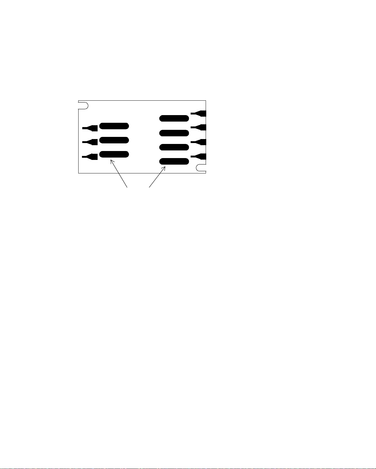
Ethernet-EnergyNet
What Are Components of EnergyLink 2500?
Figure 4-1 shows what the EnergyLink 2500 looks like before you connect the
modules. (You always mount the EnergyLink 2500 inside a 9200 controller.)
Figure 4-1. EnergyLink 2500
Cutouts in Front of Enclosure
for Modules
When you first see EnergyLink 2500, you see seven long narrow oval cutouts. You
insert a module with a single port into the unit so that its LEDs display through the
cutouts. You do not have to use all ports, only those that you need.
When you order EnergyLink 2500, you order at least one module. You can use various combinations of coaxial, twisted pair, or fiber optic modules in the ports. To
order EnergyLink 2500 and the modules, use the following Andover Controls mod-
el numbers:
• Andover Controls Model # 2500—Seven-port Ethernet Hub
(+ 5 V, powered by the 9200 controller)
• Andover Controls Model # 2501—Twisted Pair Module (10BASE-T)
• Andov er C ontrol s M odel # 2502—Thi n Coaxial Module ( 10BASE-2)
• Andov er C ontrol s M odel # 2503—Fib er Optic Module ( 10BASE- F L )
Infinity Network Configuration Guide 4-5
Page 60

Ethernet-EnergyNet
Figure 4-2 shows a port on a fiber optic module. Each fiber optic port connects to
the end of a fiber optic cable. Each coaxial port connects to the male end of a BNC
connector. Each twisted pair port connects to an RJ 11 connector.
Groove
Figure 4-2. Po rt for Fi ber Opt i c Cable
LEDs That Display
EnergyLink 2500
on
Receive
Fiber Optic
Cable Port s
Transmi t
20-pin Female Connector
Although the hub behaves the way a repeater would, you might not want to use it
as a repeater, because you would not take advantage of the seven ports. By using
various cable types in the seven ports, you can form multiple-cable-type networks.
How Do You Set the Repeater Interface Controller (RIC) DIP Switch?
You set the Repeater Interface Controller DIP switch on the EnergyLink 2500 to indicate whether the hub is using a twisted pair interface controller (for twisted pair
cable), an AUI interface controller (for c oaxial or fiber optic cable), or some combination of both.
For exact settings of the RIC DIP switch, refer to the EnergyLink 2500 Installation
Guide.
How Do You Read EnergyLink 2500’s LEDs?
EnergyLink 2500 also has LED lights that correspond to each module.
One of the LEDs on the twisted pair modules indicates polarity reversal, a potential
problem on twisted pair networks.
Both twisted pair and fiber optic cable modules have an LED for detecting a broken
wire on the cable segment.
4-6 Andover Controls Corporation
Page 61

Ethernet-EnergyNet
All types of cable have LEDs that indicate receiving data, collisi ons, and part itioning of the network at a particular arm of the hub.
See Chapter 7 or the EnergyLink 2500 Installation Guide for more details on how
to interpret the LEDs.
Figure 4-3. EnergyLink 2500 with Seven Modules
Modules with LEDs Displaying
through Cutouts in Front of Enclosure
Infinity Network Configuration Guide 4-7
Page 62

Ethernet-EnergyNet
What Is the Ethernet-EnergyNet Network Interface Card?
If you can set the EnergyNet ID of a 9200 controller by setting a DIP switch inside
the controller cabinet, how do you set it on a workstation? You set it on the network
interface card for the workstation.
Ethernet-EnergyNet supports two types of network interface cards that let you connect workstations to the network:
• Cards for IBM PC/AT and Compaq computers on an AT bus
Purchase with any of the following connector types: RJ 45, AUI, BNC, or ST.
• Cards for IBM PS/2 computers on a PS/2 bus
Purchase with any of the following connector types: RJ 45, AUI, BNC, or ST.
See your Andover Controls Representative for specific cards available.
Since the workstation with a network interface card is considered a node on the
Ethernet-EnergyNet, it must have not only an EnergyNet ID, but an Ethernet ID, just
as all other nodes on the network have.
While EnergyNet IDs for 9200 controllers range from 1 to 223, for 8000 worksta-
tions they range from 224 to 254. (EnergyNet ID number 0 is reserved by EthernetEnergyNet.) You set the EnergyN et ID on the card, according to the card manufac-
turer’s instructions. Ethernet IDs are usually preassigned when you purchase the
equipment.
To find the workstation’s Ethernet ID and then set it up in the SX 8000 software,
refer to the SX 8000 Programmer’s Guide for instructions .
4-8 Andover Controls Corporation
Page 63

Cabling Configuration for Ethernet
Chapter 5
Selecting a Cabling Arrangement for EthernetEnergyNet
We recommend you read all of the information in this chapter before designing your
own configuration. This chapter covers the following:
• Understanding Cable Types
• Forming a Simple Point-to-Point Configurat ion
with Twisted Pair Cable
• Forming a Star Configuration with Twisted Pair Cable
• Forming a Distributed Star Configuration
with Twisted Pair Cable
• Understanding Thin Coaxial Cable
• Forming a Simple Two-Node Bus
with Thin Coaxial Cable Using T Connectors
• Expanding the Simple Bus with Thin Coaxial Cable
Using T Connectors
• Lengthening the Thin Coaxial Cable Bus
• Forming a Simple Bus with Thin Coaxial
Cable Using Cable Taps
• Forming a Star or Distributed Star Configuration
wit h T hin Coa xia l C a ble Using EnergyLink 2500
• Forming a Two-Node Bus Configuration with Fiber
Optic Cable
• Lengthening the Fiber Optic Bus
• Forming a Star Configuration with Fiber Optic Cable
• Employing Multiple Cable Types in Long/Complex Networks
• Employing Bridges in Long Networks
• Planning and Setting Up a Long Network
Infinity Network Configuration Guide 5-1
Page 64

Cabling Co nf ig uration for Ethern e t
Understanding Cable Type s
When creating an Ethernet-EnergyNet, you can use any or all of the fol lowing cable
types:
• Unshielded Twisted Pair Cable
• Thick Coaxial Cable
• Thin Coaxial Cable (Thinnet or Cheapernet)
• Fiber Optic Cable
Before you find out how to design your network, let’s take a look at the
characteristics of each type of cable.
Characteristics of Unshielded Twisted Pair Cable
Unshielded twisted pair cable is telephone cable. Twisted pair cable is very
inexpensive and easy to install and maintain. In fact, you can sometimes put an
Ethernet on spare twisted pairs available on an existing telephone system.
Caution
You should always have an existing telephone system checked to be sure it is made
up of twisted pair cabling before using it for Ethernet-EnergyNet. You can have the
cable tested by a qualified cable installer or consultant. 10Base-T equipment manufacturers often provide twisted pair cable certification testing services.
For an Ethernet-EnergyNet you require two twisted pair cables, one for the transmit
signal, the other for the receive signal. The two pairs are wrapped together in a
single coating. Despi te its low cost, twisted pair cable transmits data a t a rapid rate
with less than one error in 100 million (108) bits. A twisted pair network can have
an entire network length of 1,635 ft (500 m) with segments (lengths of cable without
repeaters or between two repeaters) of up to 327 f t ( 100 m). The cable should have
a twist rate of 2 to 10 twists per foot and has a impedance of 85 to 111 Ω.
You use twisted pair cable to form an Ethernet that meets the IEEE 10Base-T
specifications.
Twisted Pair Network Topologies
You usually run twisted pair from a central location, such as a hub inside a 9200
controller, forming a star topology LAN. Or, you can run twisted pair between two
controllers, in a point-to-point topology.
Figure 5-1 shows a twisted pair star topology network.
5-2 Andover Controls Corporation
Page 65

Figure 5-1. Twisted Pair Star Topology Network
Twisted Pair Cabling
Is Always Connected
Point-to-Point
Cabling Configuration for Ethernet
Each node on the twisted pair network is connected in a point-to-point arrangement,
so that each segment of cable connects only two nodes ( the hub is also a node). Two
is the maximum number of nodes you can have on any segment of twisted pair
cable.
The connectors for twisted pair cable are like the twisted pair connector found on
the 9200 controller, an RJ 45 connector.
You cannot have bridges, taps, or T connectors on a twisted pair network; however,
you can have an EnergyLink 2500 hub mounted inside a 9200 controller.
Characteristics of Thick Coaxial Cable
You can form a coaxial Ethernet with RG 11 coaxial cable. Because of its high cost,
thick coaxial cable is rarely used for Ethernet-Ener gyNet.
This coaxial cable forms a network that meets the IEEE 10Base-5 specifications. A
network made with this “thick” coaxial cable is expensive, but has a high tolerance
for noise. You can form a thick coaxial Ethernet-EnergyNet with an entire network
length of up to 11,808 ft (3,600 m) with segments (lengths of cable without
repeaters or between two repeaters) of up to 1,640 ft (500 m).
Thick Coaxial Cable Network Topologies
You set up thick coaxial cable in a bus topology by running special transceiver cable
called “AUI cable” from each node to the coaxial cable. The thick coaxial bus is
called the “backbone.”
Infinity Network Configuration Guide 5-3
Page 66

Cabling Co nf ig uration for Ethern e t
You connect the AUI cable to the coaxial cable backbone using a special transceiver
(called a “tap”), that taps into the cable.
Figure 5-2.shows a thick coaxial bus topology network.
Figure 5-2. Thick Coaxial Bus Topology Network
Thick Coaxial Bus,
Called the “Backbone”
For information on setting up a cabling configuration with thick coaxial cable, refer
to Appendix B.
Characteristics of Thinnet Coaxial Cable
You can form another type of coaxial Ethernet with RG 58 a/u or RG 58 c/u coaxial
cable. Since this cable is thinner than that used for thick coaxial networks, such a
network is called Thinnet. Since Thinnet coaxial cable is less expensive that other
types of coaxial cable, Ethernets formed with it are sometimes called “Cheapernet.”
This coaxial cable forms a network that meets the IEEE 10Base-2 specifications.
Thinnet coaxial cable, unlike twisted pair cable, is a shielded cable. The shielding
protects the cable from noise in the environment. A Thinnet can have an entire
network length of 3,033 ft (925 m) with segments (lengths of cable without
repeaters or between two repeaters) of up to 606 ft (185 m).
Thin Coaxial Cable Network Topologies Using T Connectors
You can set up thin coaxial cable in bus topology by connecting the cable to a T
connector that you screw onto each node.
Figure 5-3 shows a thin coaxial bus topology network. This one employs T
connectors.
5-4 Andover Controls Corporation
Page 67
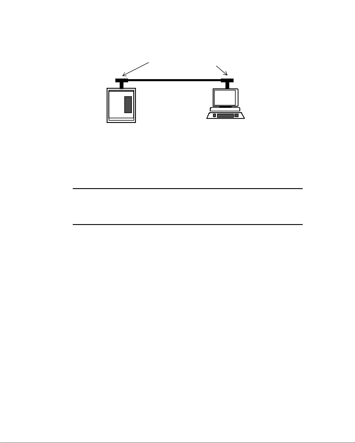
Cabling Configuration for Ethernet
Figure 5-3 . Thin C oaxial Bus To pol o gy Ne tw o rk
Terminat ed N od es
Connectors and Terminators on Thin Coaxial Cable Networks
The connectors for the RG-58 a/u or RG-58 c/u cable are T connectors. You can buy
pieces of cable with preattached T connectors to put together 10Base-2 Ethernets.
Screw-on 50 Ω terminators are required on end units of the network.
Caution
Always use premade coaxial cables, rather than trying to screw BNC connectors
onto the ends of cable pieces. Premade cables form the most reliable thin coaxial
Ethernets.
Thin Coaxial Cable Network T opologies Using Cable Taps
Instead of using T connectors, you can set up Thinnet in a bus topology by
connecting each node to a transceiver (also called a “tap”).
AUI cable “drops” from the bus and connects the transceiver to the controller or
workstation. This cable can be up to 164 ft (50 m) long. You can purchase AUI
transceivers specifically designed to attached to thin coaxial cable.
Characteristics of Fiber Op tic Cable
Fiber optic cable is the highest performance cable you can use to form EthernetEnergyNet. Fiber optic cable is made of glass or plastic and tran smits signals made
of high intensity light. B ecause of its unique nature, fi ber optic cable can t ransmit a
signal for longer distances than any other type of cable available for EthernetEnergyNet.
Fiber optic cable is also the most relia ble cable; howe ver, it is more expensive than
coaxial or twisted pair. Because it is resistant to noise, fiber optic cable is the best
cable for outdoor cable runs.
The type of fiber optic cable you can use to form Ethernet-EnergyNet is called
graded index, multimode fiber optic cable, usually 62.5/125 µm size. Throughout
Infinity Network Configuration Guide 5-5
Page 68
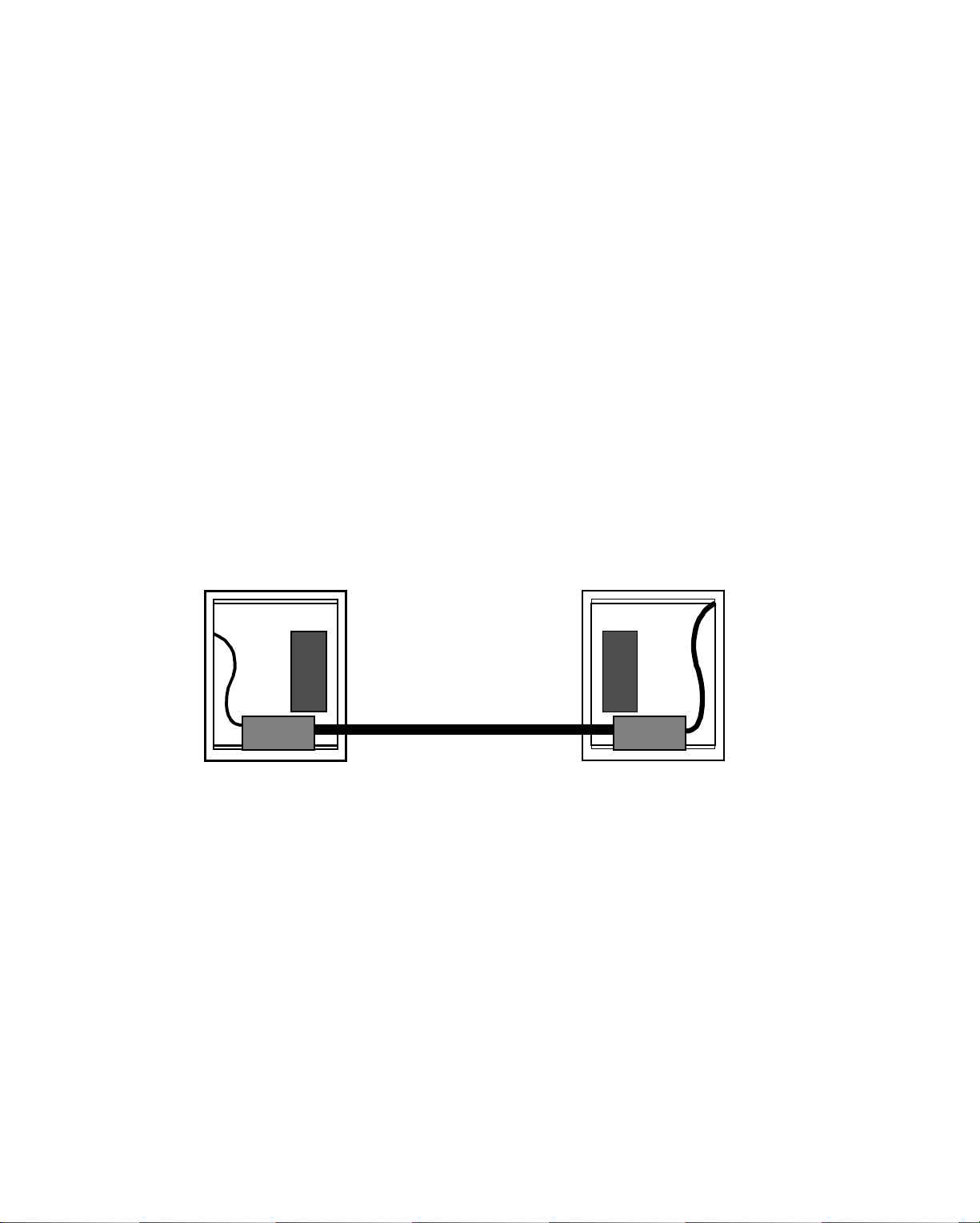
Cabling Co nf ig uration for Ethern e t
this manual, any information you see about fiber optic cable is about this 62.5/125
cable. For information on other types, refer to the manufacturer’s specifications.
The 62.5/125 fiber optic cable is ideal for the wavelength of 850 nm produced by
Ethernet transmitters . T his wavele ngth, requi re d for E therne t-EnergyNet, operates
using light emitting diodes (LEDs) to send a “signal” down the cable. Andover
recommends this cable because it meets the IEEE specificat ions f or a 10Base-F L
Ethernet and it is the most economical form of fiber optic cable—ideal f or building
automation and process control systems.
Fiber Optic Cable Topologies
You must connect fiber optic cable to the Ethernet-EnergyNet by running twisted
pair, thin coaxial, or transceiver (AUI) cable from the 9200 controller to the
EnergyLink 2500. The 2500 becomes a media changing device, where you then
connect the fiber optic cable to a fiber optic port.
The network you form this way can be a bus or a star topology.
Figure 5-4 shows a fiber optic bus topology network.
Figure 5-4. Fiber Optic Bus Topology Network
Fiber Optic Cable
5-6 Andover Controls Corporation
Page 69
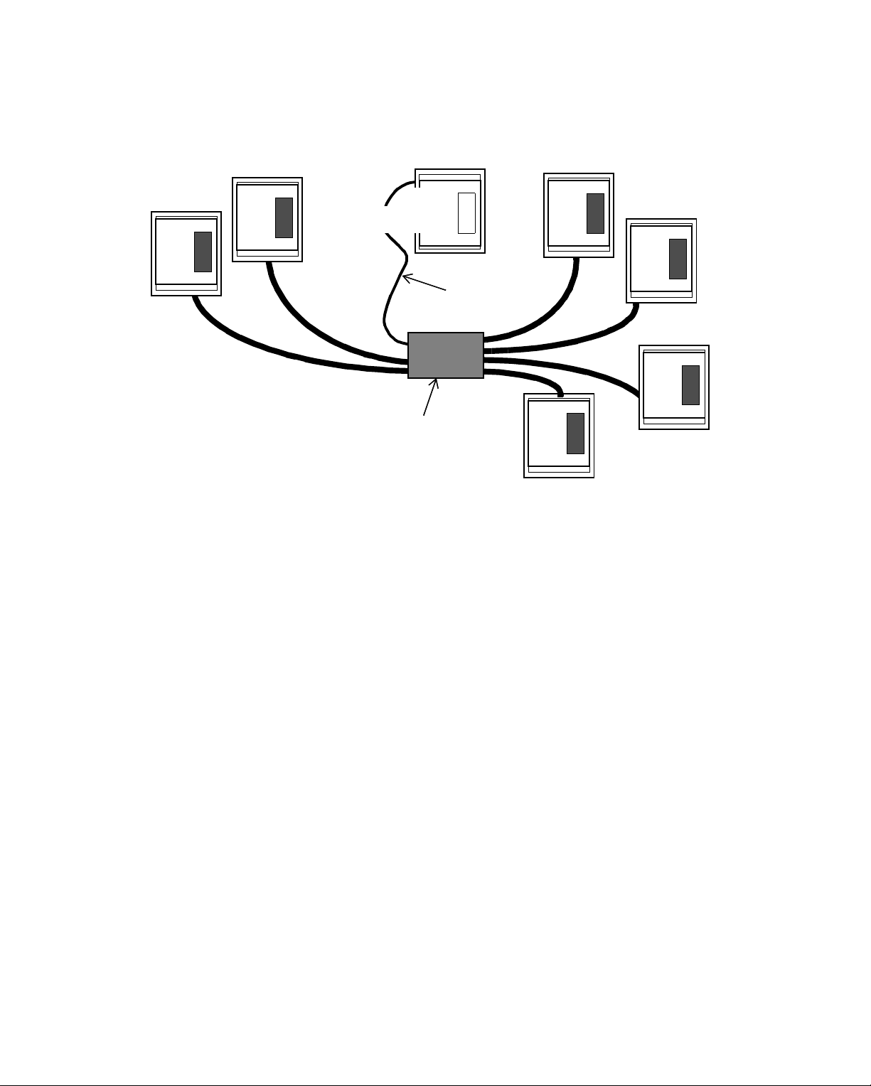
Figure 5-5 shows a star topology network.
Figure 5-5. Fiber Optic Star Topology Network
9200
Controller
Twisted
EnergyLink
2500
Hub
Cabling Configuration for Ethernet
Pair
Cable
You can also combine these two topologies to form a distributed star topology.
Regardless of the topology, each node (yes, EnergyLink 2500 is a node) on the fiber
optic network is connected in a point-to-point arrangement, so that each segment
(length of cable without repeaters or between two repeaters) connects only two
nodes. In the case of a bus, two nodes are an EnergyLink 2500 and a 9200 controller,
or an EnergyLink 2500 and a workstation. Two is the maximum number of nodes
you can have on any segment of fiber optic cable.
Connectors on Fiber Optic Cable Networks
To connect to the fiber optic port on the EnergyLink 2500, you use
ST style fiber optic connectors. Because these connectors seal the connection
tightly, they retransmit the signal from the hub with a minimal loss of light intensity.
Summary of Characteristics of Cable Types
Table 5-1 summarizes the types of cable, the minimum and maximum cable length,
the maximum network length, and number of nodes per segment for each type.
Infinity Network Configuration Guide 5-7
Page 70
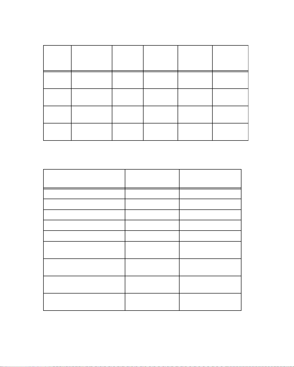
Cabling Co nf ig uration for Ethern e t
Table 5-1. Types and Characteristics of Cable for Ethernet-EnergyNet
IEEE
Cable
Type
Twisted
Pai r 10BASE-T None
Thick
Coaxial 10BASE-5
Thin
Coaxial
Fiber
Optic 10BASE-FL None
Cable Type Impedance
Network
Designation
10BASE-2
(Thinnet)
Table 5-2 lists the impedance and Belden equivalents for each cable type.
Table 5-2. Ordering Information for Ethernet-EnergyNet Cable Types
Minimum
Segment
Length
8.2 ft
(2.5 m)
20 in
(0.5 m)
Maximum
Segme n t
Length
327 ft
(100 m)
1,640 ft
(500 m)
606 ft
(185 m)
6,561 ft
(2000 m)
Maximum
Networ k
Length
1,635 ft
(500 m) 2
11,808 ft
(3,600 m) 100
3,033 ft
(925 m) 30
19,683 ft
(6000 m) 2
Brand-Rex *
Part Numbers
Maximum
Nodes per
Segment
Twisted Pair 100 Ω (85 -111 Ω) BE 57562
Twisted Pair Plenum 100 Ω (85 -111 Ω) Belden #88102
Thick Coaxial RG-11 50
Thick Coaxial RG-11 Plenum 50
Thin Coaxial RG-58 a/u or c/u 50
Thin Coaxial RG-58 a/u or c/u
Plenum 50
Fiber Optic 62.5/125
PVC Jacket
Fiber Optic 62.5/125
Plenum-Rated
Fiber Optic 62.5/125
Outdoor
µ
m,
µ
m,
µ
m,
Ω
Ω
Ω
Ω
Not Applicable HF062T2ZL (1 pr.)
Not Applicable HF062T2ZL (1 pr.)
Not Applicable HF062S2GNM (1 pr.)
RG 11
RG 11
RG 58
RG 58
HF062T4L (2 pr.)
HF062T4L (2 pr.)
HF062S4GNM (2 pr.)
5-8 Andover Controls Corporation
Page 71

Cabling Configuration for Ethernet
Forming a Simple Point-to-Point Configuration with Twisted Pair Cable
Twisted Pair (10Base-T) Ethernet-EnergyN et
Suppose you want to connect two 8000 workstations, two 9200 controllers, or one
of each. You can connect them directly from the 10Base-T connector on one 9200
controller (or the workstation interface card) to the 10Base-T connector on the
other.
Figure 5-6.shows the location of the 10Base-T RJ 45 connector in the upper left
corner of the printed circuit board on the 9200 controller.
Figure 5-6. Location on 9200 Controller of 10Base-T RJ 45 Connector Used in
Twisted Pair Configurations
10BASE-2
Coaxial
10BASE-2
10BASE-5
10BASE-T
RJ 45
for
Twisted Pair
AUI
10BASE-5
(AUI)
10BASE
2 5T
ENL PWR
10BASE- T
Ethernet
Switch
10BASE-2
10BASE-5
10BASE-T
Ethernet
Switch
Above the RJ 45 twisted pair connector and to the right you see two Ethernet
switches. Be sure to set each of these Ethernet switches to 10Base-T for twisted
pair.
Infinity Network Configuration Guide 5-9
Page 72
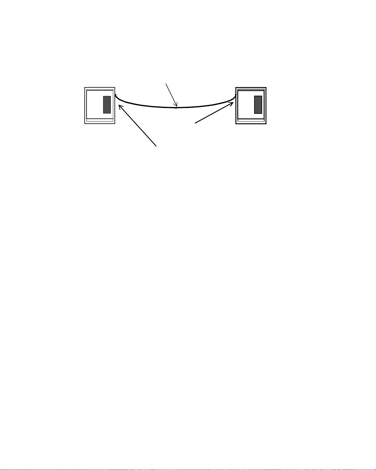
Cabling Co nf ig uration for Ethern e t
Figure 5-7.shows a two-node twisted pair point-to-point configuration.
Figure 5-7. Twisted Pair Point-to-Point Configuration
Twisted Pair Cable
9200
Controller
Each Controller
Has Built-in
9200
Controller
Twisted Pair
Port Labeled
10Base-T
You connect the twisted pair cable to the 10Base-T RJ 45 connector inside the 9200
controller, on the upper left corner of the printed circuit board. The cable you use in
this situation must be cross-over cable, rather than straight-through cable. (You find
out the difference later.)
To connect a workstation, you connect the twisted pair cable to the 10Base-T RJ 45
connector on the workstation network interface card (01-4004-014 on an AT
computer or 01-4004-018 on a PS/2 computer).
Two is the maximum number of nodes you can have on any segment of twisted pair
cable. Each node is automatically terminated at an RJ 45 connection. It is
terminated to show the node is at the end of a network—at the end of a cable or the
end of an arm of a star.
Since each controller or workstation has only one twisted pair port, you have now
used all of the twisted pair ports available on these two controllers. So, how do you
connect a third controller or workstation to this network?
You form a star configuration.
5-10 Andover Controls Corporation
Page 73

Forming a Star Configuration with Twisted Pair Cable
You can connect three to six controllers with twisted pair cable by connecting them
all to an EnergyLink 2500 hub.
Figure 5-8.shows such a star topology network with a single star. This star has the
maximum number of twisted pair cable segments allowed on an EnergyLink 2500
hub—six. Each cable connects from the hub to one other node in a point-to-point
configuration. When you connect each node to the hub, you use straight-through
cable, rather than cross-over cable.
Figure 5-8. Twis te d Pa ir S tar Topology Netw ork wi t h Maxi m um N umber of Twisted
Pair Segments Allowed on EnergyLi nk 2500
Twisted Pair Cable (Can Be Coaxial)
9200
Controller
Cabling Configuration for Ethernet
Max 327 ft. (100 m)
Twisted
Pair
Cable
EnergyLink
2500
You can also choose to use coaxial cable to connect to Port 1 of the hub (only ports
2 through 7 can have twisted pair cables) and still have six ports left for twisted pair
cable.
This configuration is ideal for a small network. B ut what if you want to develop this
network further?
Hub
Twisted Pair
Cable
8000
Workstation
Infinity Network Configuration Guide 5-11
Page 74
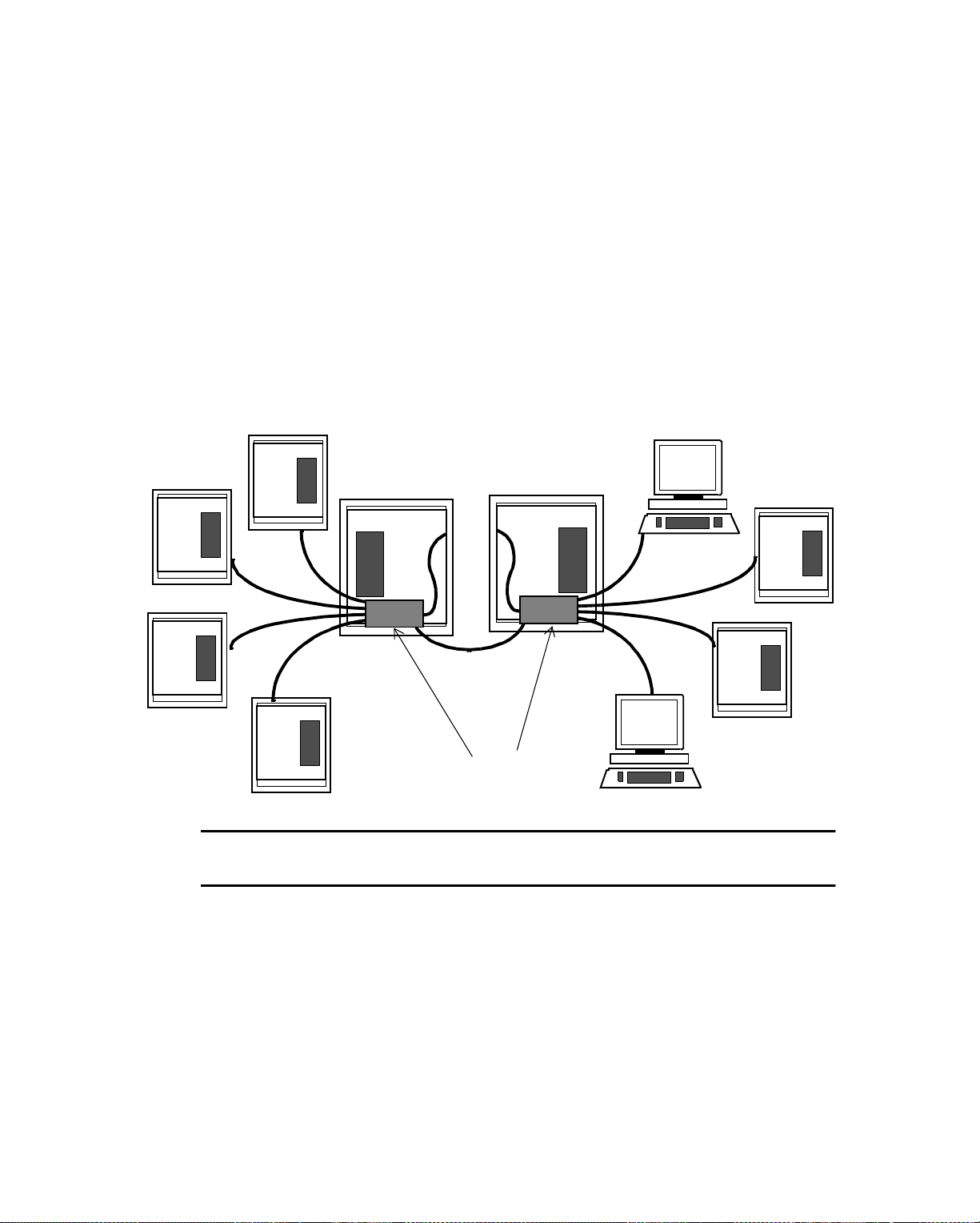
Cabling Co nf ig uration for Ethern e t
Forming a Distributed Star Configuration with Twisted Pair Cable
To have more than six controllers/workstations, you can connect a segment of
twisted pair cable from the EnergyLink 2500 to another EnergyLink 2500. This
connection is referred to as “cascading” repeaters.
Figure 5-9.shows a network with two cascaded repeaters.
Each hub then allows up to four twisted pair arms—in addition to the connections
to each other and to the controller at the center of the star.
Figure 5-9. Twisted Pair Distributed Star Topology Network wi th Two EnergyL ink 2500s
Cascaded Together
9200
Controllers
Max 327 ft.
(100 m)
Cascaded
EnergyLink 2500
Note
Remember that you can never connect twisted pair cable to Port 1 on the hub.
You can continue to cascade hubs until you have the maximum of four EnergyLink
2500s.
Figure 5-10.shows an twisted pair distributed star topology with four cascaded
hubs. Note that each hub has the maximum number of twisted pair cables connected
to it—six. One cable always connects the 9200 at the center of the star. However, if
you use coaxial cable to connect to the 9200, you can have one extra arm of twisted
pair cable in each star.
s
5-12 Andover Controls Corporation
Page 75
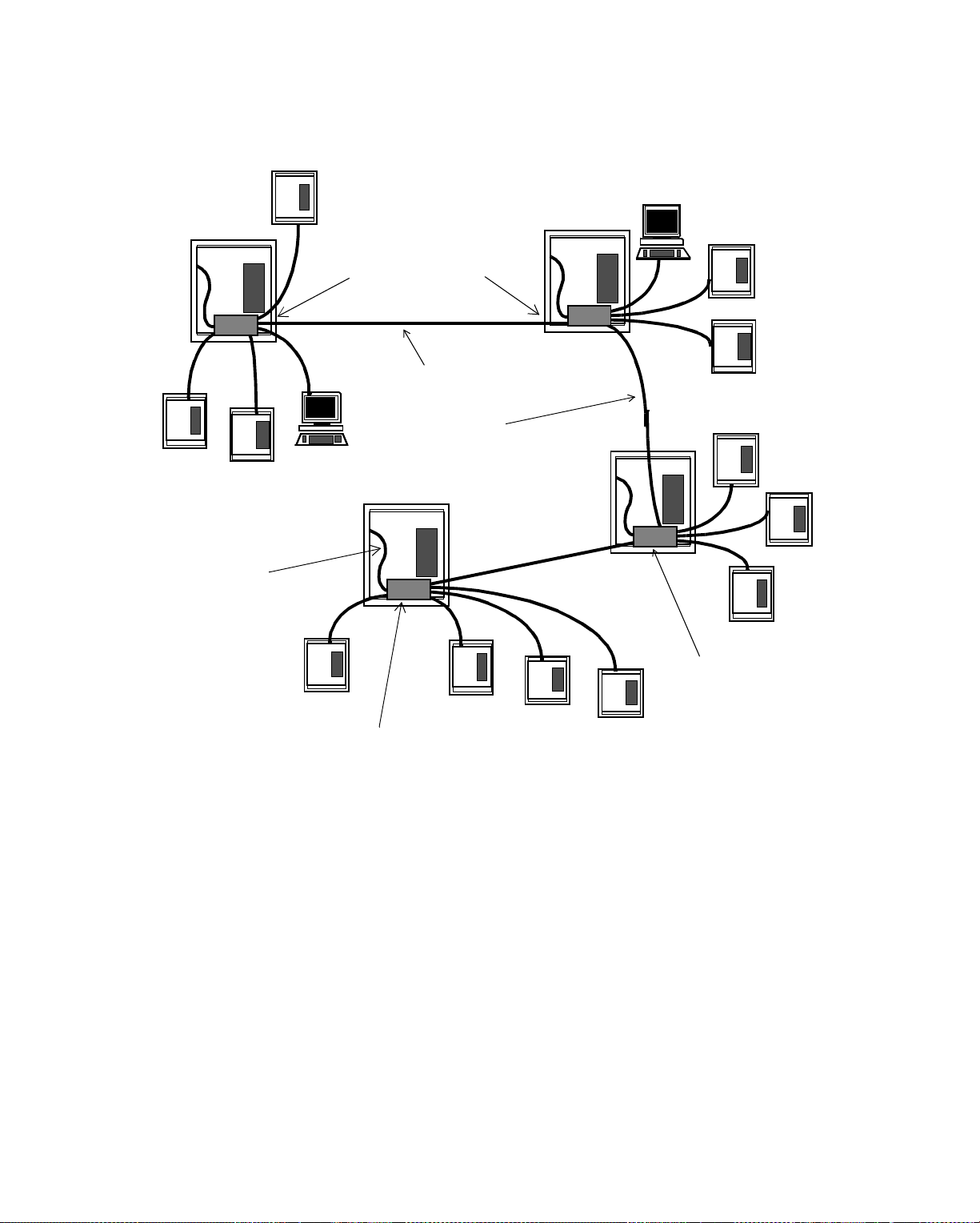
Cabling Configuration for Ethernet
Figure 5-10. Twisted Pair Distributed Star Topology Network with Four EnergyLink 2500s
Cascaded Together
Total Network Length Cannot Exceed 1,635 ft. (500 m)
Twisted Pair
Cable Th at
Connects to
9200
Controller
Housing the
Link
EnergyLink 2500
Max 327 ft. (100 m)
Twisted Pair
Cascading
EnergyLink
2500
s
s
EnergyLink
2500
EnergyLink
2500
With twisted pair cables, be sure the cable from either a 9200 or a workstation to
the EnergyLink 2500 is a straight-through cable. Cable between cascaded
EnergyLink 2500s should be cross-over cable.
Figure 5-11.shows when you should use each type of cable, cross-over or straightthrough. Notice which wires cross to form the correct cross-over cable.
Infinity Network Configuration Guide 5-13
Page 76

Cabling Co nf ig uration for Ethern e t
Figure 5-11. Wh en t o Emp lo y Twi ste d Pai r Straight-Through
or Cross-Over Cable
Straight
-Through
Cable
9200
Controller
1
2
3
6
RJ 45 Connectors
1
2
3
6
1
2
3
6
EnergyLink
2500
1
2
3
6
EnergyLink 2500
inside
5-14 Andover Controls Corporation
9200
Crossed
Pairs
inside
Cross-Over
Cable
EnergyLink 250 0
inside
9200
Page 77

Cabling Configuration for Ethernet
Rules for Twisted Pair Networks
If you choose to employ twisted pair cable, be sure your network meets the
following criteria:
• Follow National Electrical Code (NEC) restrictions if running cable through
HVAC plenums or ducts. You can use Teflon-coated cable in this situation if
the code requires it.
• Be sure the amount of cable between nodes (a single segment of cable) does not
exceed 327 ft (100 m).
• Be sure you never have more than two nodes on a single segment of cable.
•Each E n ergyLink 2500 is a node on the network.
• To form a star topology, use EnergyLink 2500 as a hub.
• Be sure the overall network is does not exceed 1,635 ft (500 m).
Infinity Network Configuration Guide 5-15
Page 78
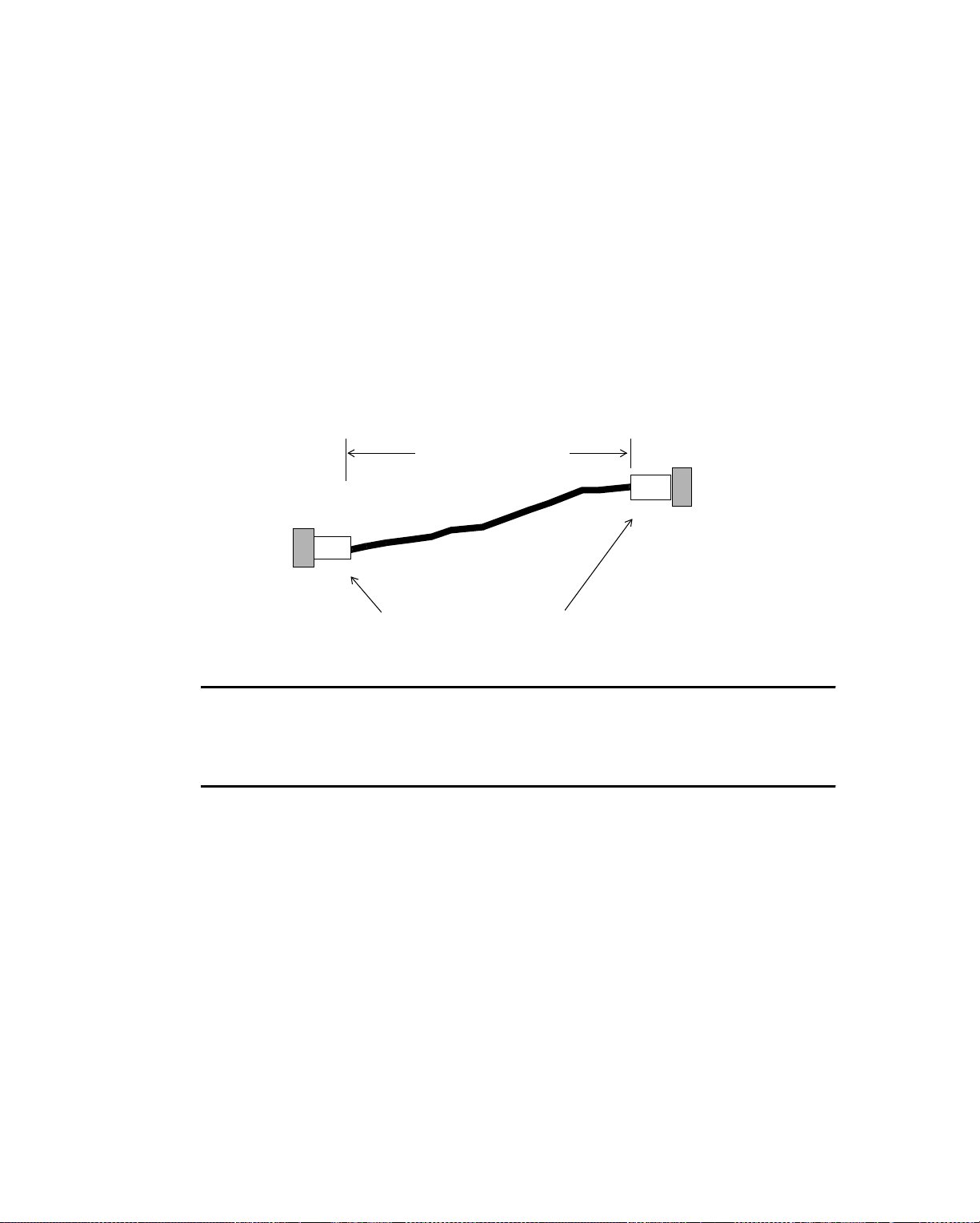
Cabling Co nf ig uration for Ethern e t
Understanding Thin Coaxial Cable
Using Coaxial Cables
No matter which type of network topology you use, if you are using coaxial cable,
each piece of thin coaxial cable connecting to a controller, workstation, or
EnergyLink 2500 must have a BNC male connector at both ends. You should use
premade cables, because premade cables provide the most trouble-free networks.
Figure 5-12.shows a single piece of premade coaxial EnergyNet cable. Each piece
of coaxial cable from male connector to male connector must be at least 20 in. (0.5
m) long for Ethernet.
Figure 5-12. Premade Ethernet-EnergyNet Thinnet Coaxial Cable with Connectors
20 in. (0.5 m)
minimum
Male Connectors
on either end of Coaxial Cable
Note
Remember that a piece of cable differs from a segment. A segment of thin coaxial
cable is between two repeaters or hubs. A piece of thin coaxial cable is between
two controllers.
5-16 Andover Controls Corporation
Page 79
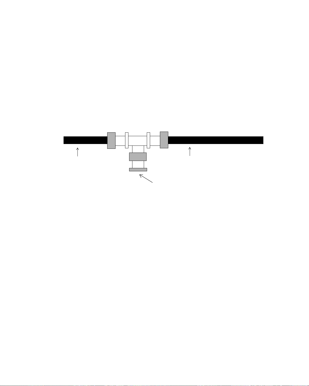
Cabling Configuration for Ethernet
Forming a Simple Two-Node Bus with Thin Coaxial Cable Using T Connectors
Suppose you want to connect two 8000 workstations, two 9200 controllers, or one
of each. To connect two nodes, you first connect a T connector to each node and
terminate the nodes.
Figure 5-13.shows the EnergyNet coaxial T connector (Andover Controls Model #
2070). Every T connector on the network has three ends. The bottom of the T al-
ways connects to the coaxial connector on a controller, workstation, or EnergyLink
2500 on the network.
Figure 5-13. Ethernet-EnergyNet Coaxial T Connector
Coaxial Cable
Coaxial Cable
Screws onto Controller,
Workstation, or
The two sides of the T connector usually connect to a coaxial cable, but if you are
terminating the network at the controller or workstation, you connect cable to one
side of the T and attach a 50 Ω terminator to the other side of the T.
Where does the T connector attach to a 9200 controller?
Figure 5-14.shows where you connect the coaxial connector in the upper left corner
of the printed circuit board inside the 9200 controller. After you screw on the T
connector, if the node should be terminated, screw a 50 Ω terminator onto the open
side of the T connector, as shown in the figure.
Next, look to the right of the coaxial connector and down. You see two Ethernet
switches. Be sure you set both of them to 10Base-2.
EnergyLink 2500
Infinity Network Configuration Guide 5-17
Page 80
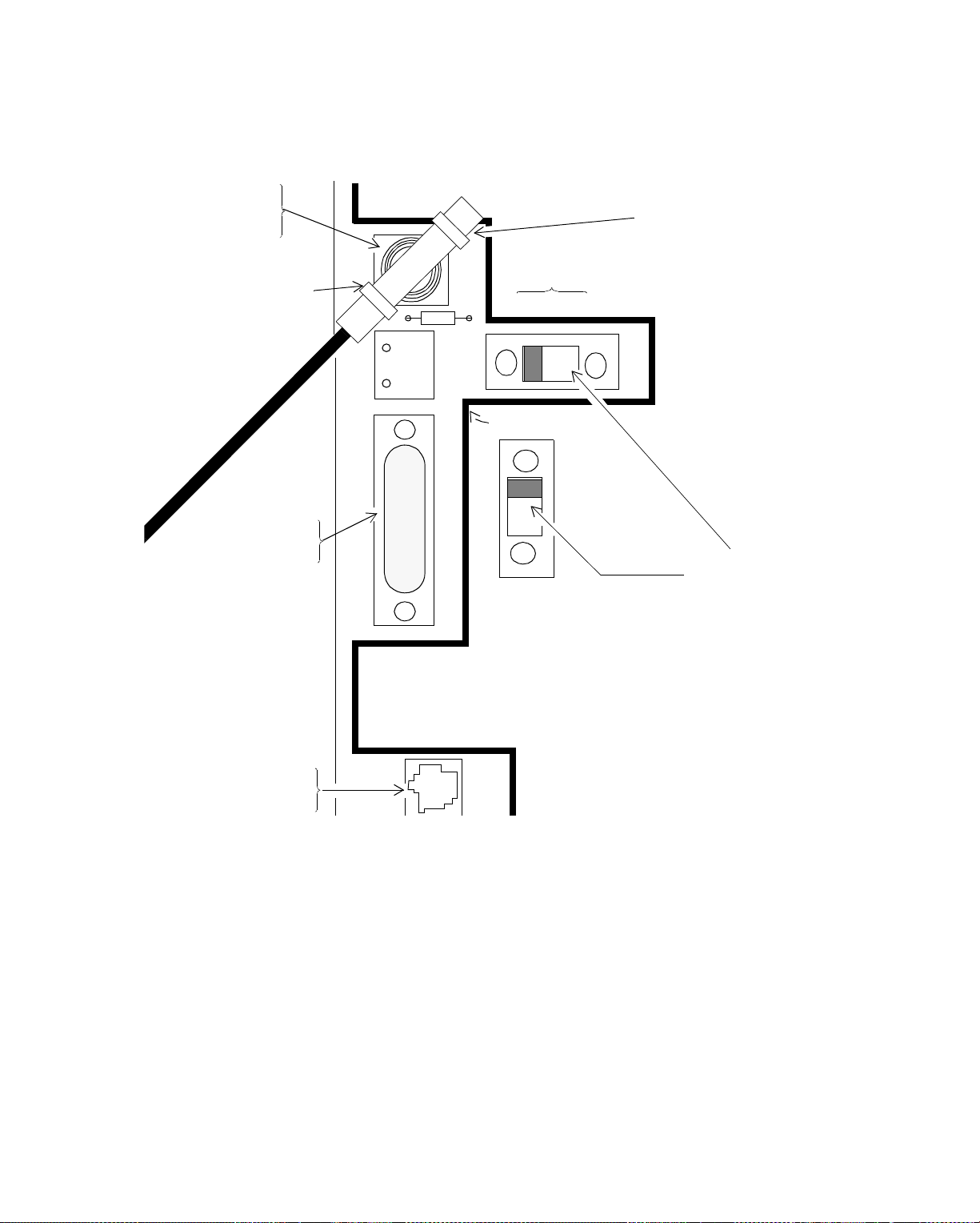
Cabling Co nf ig uration for Ethern e t
Figure 5-14. Location on 9200 Controller of Coaxial Connector Used in Thin Coaxial Bus
Configuration with Built-in Transceivers
10BASE-2
Coaxial
50 Ω
Terminator
Coaxial T
Connector
10BASE-5
AUI
10BASE
2 5T
ENL PWR
10BASE-2
10BASE-5
10BASE-T
Ethernet
Switches
10BASE-5
(AUI)
10BASE-T
RJ 45
On a workstation, the T connector screws onto the network interface card (01-4004016 for AT computers and 01-4004-020 for PS/2 computers). And on an
EnergyLink 2500, the T connector screws onto a coaxial port.
Now, connect the premade thin coaxial cables to open sides of the T connector on
each node.
Figure 5-15.shows how the thin coaxial Ethernet-EnergyNet cable connects to the
T connector.
5-18 Andover Controls Corporation
10BASE-T
Page 81
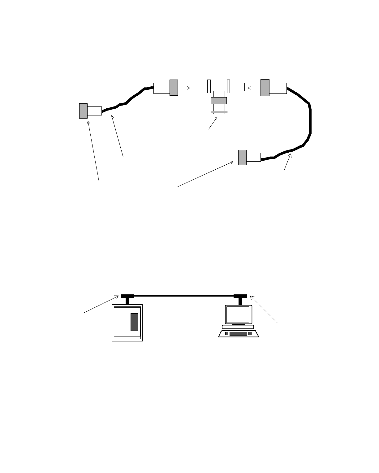
Cabling Configuration for Ethernet
Figure 5-15. Ethernet-EnergyNet Thin Coaxial Cable Connecting to T Connector
Male BNC
Connector
BNC T
Connector
Male BNC
Connector
Connects to Controller
or Workstation
Premade Cable
Premade Cable
Connect to Another
Node’s T Connector
Figure 5-16.shows the resulting simple point-to-point connection in a bus t opology
with no hub. In this situation, since each node is at an end of the network, each node
must be terminated.
Figure 5-16 . Two-No de Point-to- Point B us Topol ogy
Thin Coaxial Ethernet-EnergyNet with T Connectors
Controller T Connector
Is on Printed Circuit Board
Terminator
Screws
on Here
9200
Controller
Controller and Workstation
Works tation T Connector
Is on Network Interface
Card
Min 8.2 ft. (2.5 m)
Max 606 ft. (185 m)
Terminator
Screws
on Here
8000
Workstation
Are Both Terminated
Infinity Network Configuration Guide 5-19
Page 82

Cabling Co nf ig uration for Ethern e t
Expanding the Simple Bus w ith Thin Coaxial Cable Using T Connectors
To add more controllers/workstations to the two-node bus formed with T
connectors, you first screw a T connector to each new node.
Then return to the two-node bus you developed earlier and remove the terminator
from the end you want to extend. Connect a piece of premade cable to the open side
of the T connector. Then connect the other end of the premade cable to the T
connector on another node.
Repeat this process until you reach the last node. Then be sure to screw the 50 Ω
terminator onto the last node. You can connect 30 nodes like this on up to 606 ft
(185 m) of thin coaxial cable.
Figure 5-17.shows an expanded bus topology formed with thin coaxial cable and T
connectors.
Figure 5-17. Expanded Bus Topology Thin Coaxial Ethernet-EnergyNet with T Connectors
Max Segment without Repeater 3,033 ft. (925 m) w/ Up to 30 Controllers
Min 8.2 ft. (2.5 m)
Max 606 ft. (185 m)
The Two End Nodes
Are Terminated
5-20 Andover Controls Corporation
Page 83

Cabling Configuration for Ethernet
Lengthening the Thin Coaxial Cable Bus
Now that you have extended the thin coaxial Ethernet-EnergyNet as far as possible,
how do you have more than 606 ft (185 m) of cable on the network and make a
network the total network length of 3,033 ft
(925 m)? How do you add more than 30 nodes?
The answer to both of these questions is that you use the EnergyLink 2500 as a
repeater to build a longer network and the longer network then allows you to add
more nodes, since every other 606 ft (185 m) segment allows up to 30 nodes.
Why every other segment? Because once you have at least three EnergyLink 2500s,
you must have inter-repeater links (IRLs). An inter-repeater link is cable that
connects two repeaters, but has no controllers or workstations on it.
Figure 5-18.shows where the inter-repeater links would be if you used the
maximum of four EnergyLink 2500s with five segments of cable. Notice that the
EnergyLink 2500s are connected to each other. This arrangement is called
“cascading” hubs.
1
You can also form inter-repeater links on a 10Base-2 Ethernet-EnergyNet using
twisted pair or fiber optic cable. Be sure, however, that the segment length is not
longer than allowed for that cable type.
1. Remember, how ever, that s in ce
stations on th e segme nt of cabl e may be onl y 29, since the
EnergyLink 2500
is also a node, the number of controllers/work-
Infinity Network Configuration Guide 5-21
EnergyLink 2500
becomes the 30th node .
Page 84

2
0
5
Max 606 ft. (185 m)
& 29 Controllers
or Workstations
nk
i
L
gy
Max 606 ft.
(185 m)
& No
Controllers
or
er
Workstations
n
E
(each housed in
a 9200 controller)
Inter-Repeater Links
Max 606 ft. (185 m)
& 29 Controllers
or Workstations
s
Li
gy
Max 606 ft.
(185 m)
r
& No
Controllers
or
Workstations
e
n
E
(each housed in
a 9200 controller)
nk 250
Max 606 ft.
(185 m)
& 29 Controllers
or Workstations
s
Total Network Length Cannot Exceed 3,033 ft. (925 m)
Cabling Co nf ig uration for Ethern e t
Figure 5-18. Inter-Repeater Links on Thin Coaxial Ethernet-EnergyNet Bus
5-22 Andover Controls Corporation
Page 85
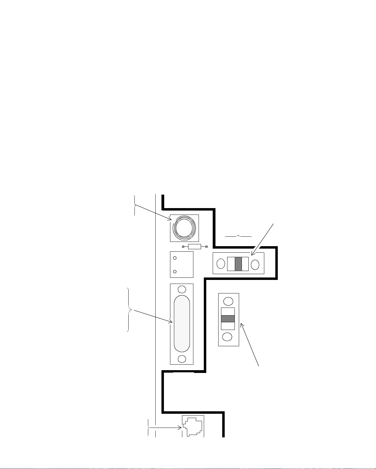
Cabling Configuration for Ethernet
Forming a Simple Bus with Thin Coaxial Cable Using Cable Taps
Another way of forming a bus with thin coaxial cable is to attach up to 164 ft (50
m) of a special cable called AUI cable to the Attachment Unit Interface (AUI) port
on each 9200 controller or workstation network interface card.
Figure 5-19.shows the location of the AUI port in the upper left corner of the printed
circuit board on the 9200 controller.
After you connect the AUI cable to the AUI port, look to the right and up. You see
two Ethernet switches. Be sure you set both of them to 10Base-5. Why 10Base-5
for a 10Base-2 network? Because whenever you use the AUI port, you must
always set the Ethernet switch to 10Base-5.
Figure 5-19. Location of AUI Port on 9200 Controller and Settings of Ethernet Switches
When Using AUI Cable to Connect to a Thin Coaxial Cable Network
10BASE-2
Coaxial
Set This Ethernet
Switch to 1 0Base-5
10Base-5
AUI Port
to Connect
AUI Cable
10BASE-5
(AUI)
10BASE
2 5T
10BASE-2
10BASE-5
10BASE-T
Set This Ethernet
Switch to 10Base-5
10BASE-T
RJ 45
10BASE-T
Infinity Network Configuration Guide 5-23
Page 86
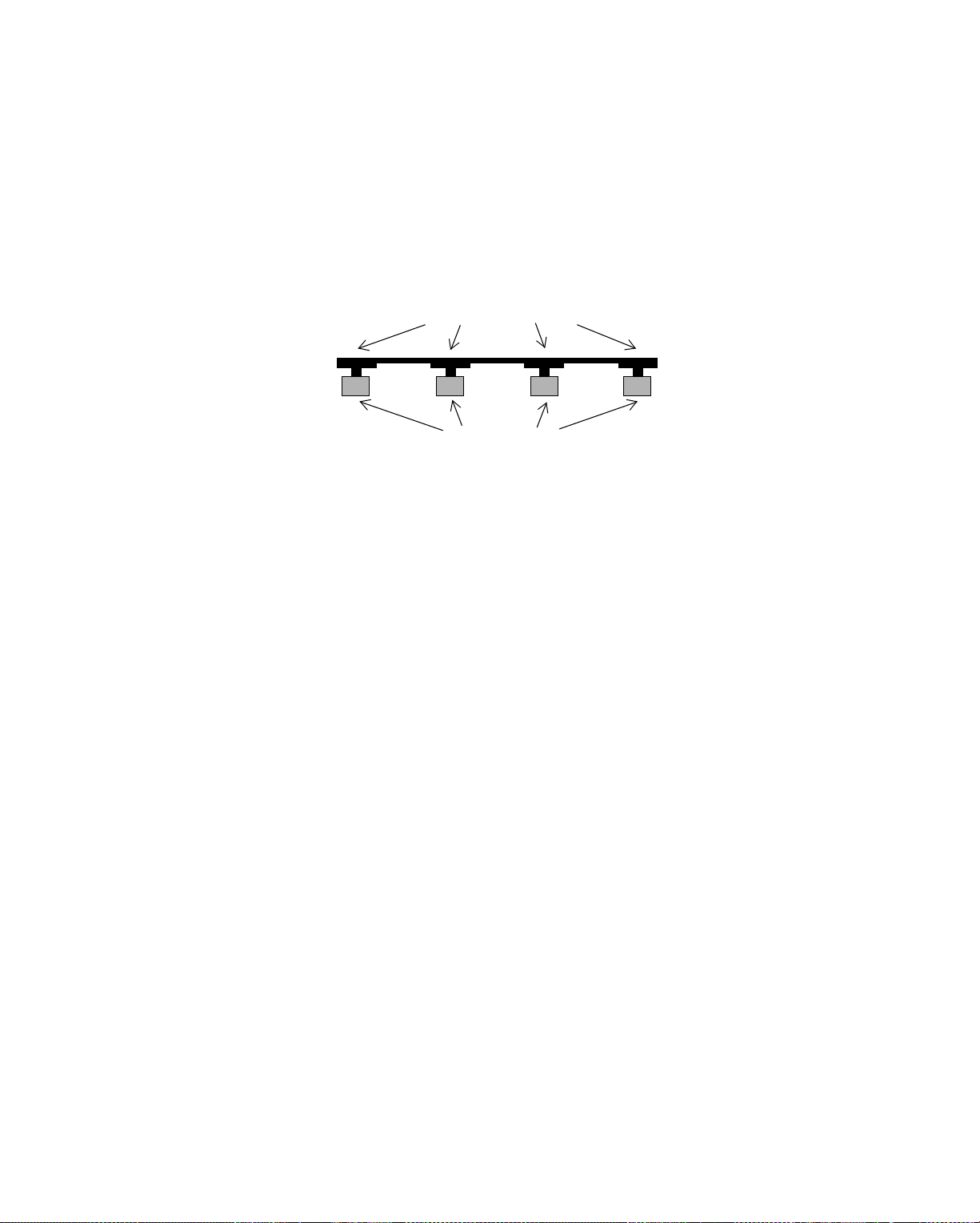
Cabling Co nf ig uration for Ethern e t
You then connect the pieces of thin coaxial cable to special transceivers (also called
“taps”), so that a series of taps are lined up on the bus. The taps you can purchase
to use with thin coaxial cable each have a built-in T connector (01-4006-002) so the
male BNC connectors on the ends of the coaxial cable screw directly onto the taps.
Figure 5-20.shows the taps along a thin coaxial bus.
Figure 5-20. Transceivers (Taps) on a Thin Coaxial Bus
T Connec tor s
Transceiver
{
MAU Ports
Each tap has a built-in T connector on one side and a Medium-Attachment Unit
(MAU) port on the other. This port is where you plug in the AUI cable.
Figure 5-21.shows the AUI cable connecting to the 9200 controller AUI port on one
end and to the MAU port on the transceiver at the other end.
5-24 Andover Controls Corporation
Page 87

Cabling Configuration for Ethernet
Figure 5-21. AUI Cable Connecting 9200 Controller to Thin Coaxial Cable Transceiver
Female AUI Port
on
9200
Controller
Male Connector
on Transceiver
Cable
AUI Cable
Minimum of 20 in. (0.5 m)
Maximum of 164 ft. (50 m)
Male
Connecto r
on MAU
of Transceiver
Female Connector
on Transceiver
Cable
Thin Coaxial Cable
Transceiver
Figure 5-22.shows the thin coaxial bus with cable taps.
Figure 5-22. Controllers Connected to Transceivers on Thin Coaxial Bus via AUI
Cable
Thin Coaxial Cable
Max 606 ft. (185 m) with up to 30 Taps
Transceiver
}
AUI
Cables
(Between
20 in. (0.5 m)
and 164 ft.
Each Controller Has Built-in AUI Port
The tap transforms the signal it receives from the AUI cable so that the signal can
be sent down the coaxial cable.
(50 m))
Infinity Network Configuration Guide 5-25
Page 88

Cabling Co nf ig uration for Ethern e t
You can have as many as 30 ta ps on a 606 ft (185 m) segment of th in coaxial
cable. The distance between each tap must be a minimum of 20 in. (0.5 m).
The AUI cable to the transceiver from the controller or workstation can be up to 164
ft (50 m).
Why would you use this type of bus? Because it allows you to drop a cable from a
tap on the bus to the controller or workstation. If you use T connectors instead, you
cannot drop any cable from, for instance, a T connector in the ceiling to the
controller or workstation. With T connectors, you must run the bus directly to the T
connector and have the T connector directly on the controller board or workstation
network card. With AUI cable, however, you can run the bus through the ceiling
and then drop down from it. This alternative, often ref erred to as a “cable drop,” can
be extremely convenient in many installations.
However, using AUI cable does add to the amount of total delay on the network
and, thereby, does influence the total length of the network. You learn more about
how delays influence the total length of the network later, when you attempt to use
a variety of cable types in one network.
5-26 Andover Controls Corporation
Page 89
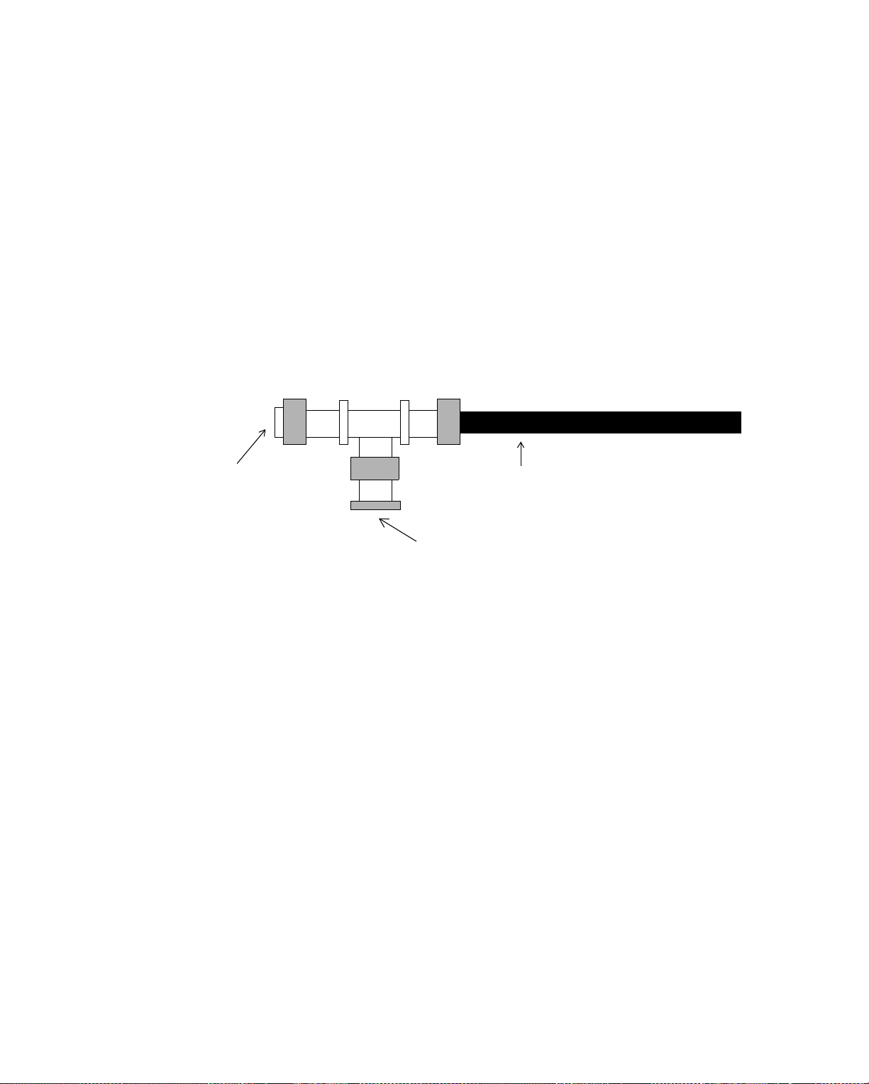
Cabling Configuration for Ethernet
Forming a Star or Distributed Star Configuration with Thin Coaxial Cable Using EnergyLink 2500
To put more than 30 nodes on a thin coaxial Ethernet-EnergyNet, you can form
stars. The way to form stars is to mount the EnergyLink 2500 inside the 9200
controller. The EnergyLink 2500 hub becomes the center of a star with a maximum
of six additional thin coaxial arms.
As shown in Figure 5-23, when you connect thin coaxial cable directly to the hub
ports, you should screw the bottom of a T connector to the hub, terminate one side
of the T connector with a 50 Ω terminator, and connect coaxial cable to the other
side of the T connector.
Figure 5-23. Ethernet-EnergyNet Coaxial T Connector
50 Ω Terminator
Coaxial Cable
Screws onto Coaxial
Port of
Figure 5-24.shows a thin coaxial star with an EnergyLink 2500 hub at the center.
This particular network has only a single controller or workstation on each arm of
the star. In this configuration, you would terminate each node and terminate the
other end of each two-node bus at the EnergyLink 2500.
Note that in this configuration, because you have more than two coaxial cables
connecting to the hub, you must have an external power supply wired to the hub.
EnergyLink 2500
Infinity Network Configuration Guide 5-27
Page 90
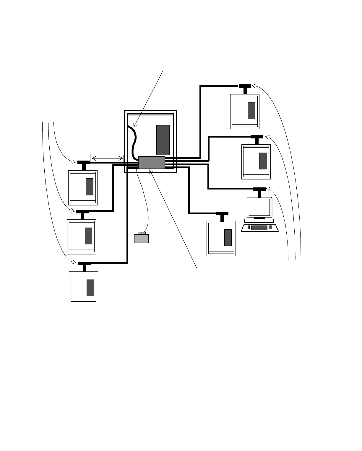
Cabling Co nf ig uration for Ethern e t
Figure 5-24. Thin Coaxial Star Topology Network
Thin Coaxial Cable
can fo rm a star
configuration with
EnergyLink 2500
Terminated
Nodes
Max 606 ft.
(185 m)
Coaxial or Twisted Pair Cable
can connect
9200
to hub
External
Power Supply
required for
more than
two Coaxial
EnergyLink
2500
Hub
Terminated
Nodes
Cables on hub
You can connect the central 9200 of the star to the hub using one of two alternate
types of cable:
• Thin coaxial cable, running from the coaxial 10Base-2 connector inside the
9200 to a coaxial port on the EnergyLink 2500.
• Twisted pair cable, running from the RJ 45 10Base-T connector inside the 9200
to a twisted pair port on the EnergyLink 2500.
To further expand this star, you can add nodes onto each arm, so each one forms a
bus.
Figure 5-25.shows a thin coaxial star with an EnergyLink 2500 hub at the center.
This particular network has a bus with up to 29 controllers/workstations on each
arm of the star.
5-28 Andover Controls Corporation
Page 91
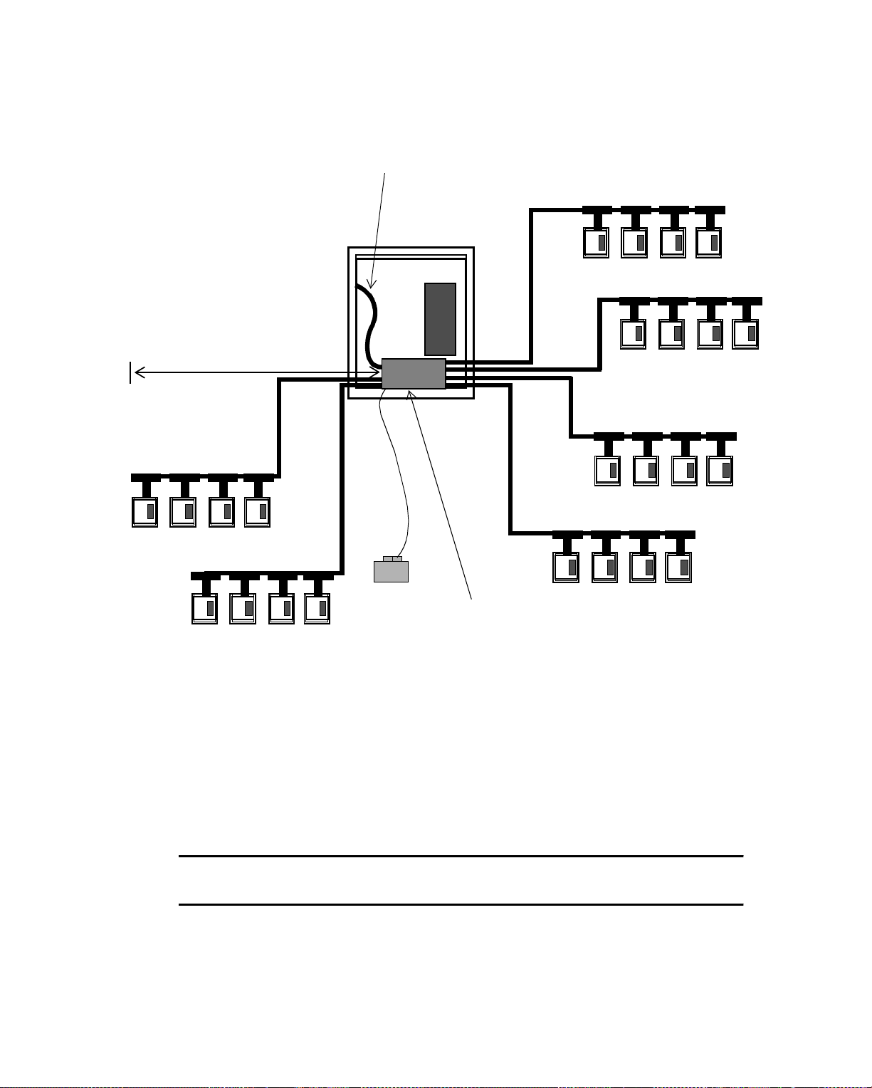
Cabling Configuration for Ethernet
Figure 5-25. Thin Coaxial Distributed Star Topology Network with a Single Hub
Thin Coaxial or Twisted Pair Cable
Can Connect
9200
to Hub
Each Thin Coaxial
Arm of a Star Can
Be a Bus with
up to 30 Nodes
Max 606 ft. (185 m)
Up to 30 Nodes
EnergyLink
2500
You terminate the node at the end of each bus and terminate the coaxial port on the
EnergyLink 2500. Remember, you can also lengthen some buses with EnergyLink
2500s, as long as you never use more than four EnergyLink 2500s per network and
you observe the rules concerning inter-repeater links (IRLs).
Figure 5-26.shows a distributed star topology with two cascaded hubs. Using this
kind of configuration, you can have up to 150 nodes on a single star. You can have
up to four cascaded hubs, but should never exceed the Ethernet-EnergyNet
maximum of 50 nodes.
Caution
Never cascade more than four hubs.
Hub
Infinity Network Configuration Guide 5-29
Page 92

Cabling Co nf ig uration for Ethern e t
Figure 5-26. Thin Coaxial Distributed Star Topology Network with Two Cascaded Hubs
Thin Coaxial or Twisted Pair Cable
Can Connect
9200
to Hub
You Can Cascade
Together Multiple
EnergyLink 2500
s
to Connect Multiple
Thin Coaxial Stars
Max 606 ft.
Max 606 ft. (185 m)
Up to 30 Nodes
If you want to put a node on the thin coaxial network with twisted pair cable, you
can use a twisted-pair-to-coax adaptor (01-3004-001). The adaptor has a RJ 45
connector on one side and a male BNC connector on the other side.
The adaptor is effective for up to 327 ft (100 m) of twisted pair and
327 ft (100 m) of coaxial cable.
You can employ this kind of adaptor in situations where you want to connect a
single node to the bus rather than forming a star. Since you can have a maximum of
four EnergyLink 2500s , by using the adaptor you can save the hubs for situations
where you really need them.
(185 m) Up to 30 Nodes
5-30 Andover Controls Corporation
Page 93
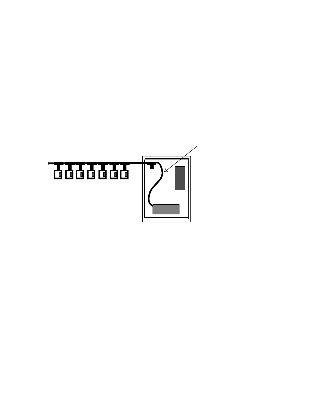
Cabling Configuration for Ethernet
EnergyLink 2500 as a Node on Each Bus
On an arm of a star, you can actually have 30 nodes—29 of them controllers or
workstations and one the EnergyLink 2500. When the center of the star joins
multiple buses, which bus is the EnergyLink 2500 on? It is a node on each bus that
terminates at the hub.
The next three figures each illustrate a way of putting together buses with the
EnergyLink 2500.
Figure 5-27.shows the 9200 housing the EnergyLink 2500 and both units on the
same coaxial bus.
Figure 5-27. Both 9200 and Hub on Same Thin Coaxial Bus
Both
9200
and
hub on same
Bus with Up to 28 Other Nodes
Thin Coaxial bus
(This cable is part
of the bus)
In this arrangement, since both the EnergyLink and the 9200 are on the sa me coa xial
bus, that bus can have only 28 other nodes, because the 9200 and the hub are the
other two nodes.
As shown in Figure 5-28, another way to connect the EnergyLink 2500 to a bus is
to connect the bus directly to a coaxial por t on the hub so that the 9200 that houses
the hub is on another coaxial bus. This way, because the bus does not include the
9200 housing the hub, it can have 29 other nodes. (Although not shown, you can
have up to four coaxial buses on the hub.)
Infinity Network Configuration Guide 5-31
Page 94
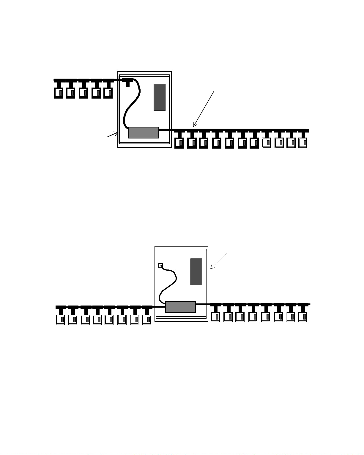
Cabling Co nf ig uration for Ethern e t
Figure 5-28. 9200 and Hub on Different Thin Coaxial Buses
Bus with Up to
28 Other Nodes
29th node on
bus to left
Figure 5-29.shows yet another alternative. This alternative is a way to join two coaxial buses that each have 29 controllers or workstations. The configuration
connects each bus to an EnergyLink 2500 and has the 9200 that hous es the hub con-
nect to the hub using twisted pair cable.
Hub is on this Thin Coaxial
Bus, and the
9200
that houses
the Hub is on another bus
(shown to the left)
Bus with up to 29 other nodes
Figure 5-29. 9200 Not on a Bus and EnergyLink 2500 Central Hub for Two Thin Coaxial
Buses
Single Central
9200
Connected to Hub with
Twisted Pair Cable
Other Buses
Connected Directly
to Hub Ports
Bus with up to 29 other nodes
Remember, whenever you use twisted pair cable, you connect only two nodes; in
this case those nodes are the 9200 and the EnergyLink 2500.
Bus with up to 29 other nodes
Rules for Thin Coaxial Cable Distributed Star Topol ogy Networks
You must adhere to the following when creating a thin coaxial cable bus topology
Ethernet-EnergyNet:
• To use T connectors:
5-32 Andover Controls Corporation
Page 95

Cabling Configuration for Ethernet
— Terminate the controllers at both ends of an arm by screwing
a 50 Ω terminator into the T connector on each controller. To terminate a
workstation, refer to the instructions included with the network interface
card.
— Use Andover Controls T connectors (Andover Controls Model
# 2070) to connect controllers or workstations directly to the bus.
• To use cable taps:
— Use Andover Controls thin coaxial cable taps to tap directly into the thin
coaxial cable and then run AUI cable from the tap to the controller or
workstation AUI port.
— Connect each controller/workstation to the cable tap with up to 164 ft (50
m) of AUI cable.
•Use an EnergyLink 2500 as the cent er of the star .
• Keep the length of an arm or cable segment at a maximum of 606 ft (185 m).
• Keep the maximum number of nodes per arm to 30, including the EnergyLink
2500. This means the following:
You can have up to 29 controllers and/or workstations on a bus that
connects directly to the
On a bus that includes both the hub and the
EnergyLink 2500
.
9200
controller that
houses it, you can have up to 28 additional controllers and/or
workstations.
• Remember, the EnergyLink 2500 is a node on every bus that connects to it.
• Be sure each piece of cable from node to node or cable tap to cable tap is a
minimum of 20 in (0.5 m) long.
• Connect the EnergyLink 2500 to the controller that houses it using twisted pair
cable to maximize the number of nodes on the thin coaxial bus.
• You can add segments to the network using EnergyLink 2500.
• Keep the total network length at a maximum of 3,033 ft (925 m).
Infinity Network Configuration Guide 5-33
Page 96

Cabling Co nf ig uration for Ethern e t
Forming a Two-Node Bus Configuration with Fiber Optic Cable
Andover Controls recommends you use glass fiber optic cable for running EthernetEnergyNet cable between buildings or through a high-noise environment. You may
choose to form an entire bus of fiber optic cable or merely extend another type of
network between buildings with fiber optic cable.
Suppose you want to connect a 9200 controller to another 9200 controller using
fiber optic cable.
How do you connect fiber optic cable to a controller when it has connectors for
coaxial cable, twisted pair, and AUI cable, but no connector for fiber optic cable?
You run either thin coaxial or twisted pair cable from the controller to an
EnergyLink 2500. The EnergyLink 2500 should have at least one module for either
twisted pair or thin coaxial cable. The other modules ca n all be for fiber optic ca ble.
You then run fiber optic cable from one EnergyLink 2500 to another, cascading
them together.
Figure 5-30.shows a two-controller fiber optic bus topology network with
EnergyLink 2500s (you can have the same arrangement with workstations or a
controller and a workstation). You cannot have any nodes along the bus between
these two controllers, because you can never have more than two nodes on a single
segment of fiber optic cable.
Figure 5-30. Tw o-C on t rol l er Fi ber Optic Bus Top ol ogy
Ethernet-EnergyNet
Since Thin Coaxial Cable
Can Be Thin Coaxial
or Twisted Pair
Cable Connecting
Buses Must Be Terminated at Both
Ends of the Coaxial Connector,
This Port on the Hub Is Terminated
Controller to Hub
Fiber Optic Cable
Max 6,561 ft. (2000 m)
5-34 Andover Controls Corporation
EnergyLink
2500
s
Page 97

Cabling Configuration for Ethernet
You can also put workstations on the fiber optic bus by connecting cable to the fiber
optic port on the network interface card of the workstation (01-4004-017 for an AT
computer, 01-4004-021 for a PS/2 computer).
Infinity Network Configuration Guide 5-35
Page 98
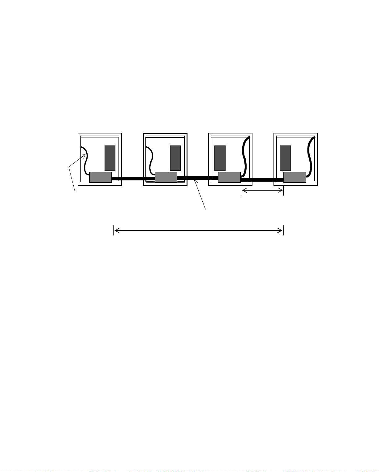
Cabling Co nf ig uration for Ethern e t
Lengthening the Fiber Optic Bus
To lengthen the fiber optic bus, you add another node the same way you put the first
two controllers onto the bus. You can have up to four repeaters, so you can add a
maximum of four controllers onto the bus.
Figure 5-31.shows a four-controller fiber optic bus topology with EnergyLink
2500s. (This bus actually has eight nodes, including the EnergyLinks.)
Figure 5-31. Fo ur- C o nt ro lle r Fi ber Optic Bus Top ology
Coaxial or Twisted
Pair Cable
Max 6,561 ft.
(2000 m)
Fiber Optic Cable
Total Network Cannot Exceed 19,683 ft. (6000 m)
5-36 Andover Controls Corporation
Page 99

Forming a Star Configuration with Fiber Optic Cable
You can also use the EnergyLink 2500 to form a fiber optic star.
The EnergyLink 2500 can have up to seven fiber optic ports. You need, however, to
have at least one port on each hub be either a twisted pair or coaxial cable port so
that you can connect the 9200 controller to the hub.
Figure 5-32.shows a four-arm fiber optic star topology with EnergyLin k 2500s.
Notice that this star does not require an external power supply for the hub. The hub
requires external power when you have more than four fiber optic cables connected
to it.
Figure 5-32. Four- A r m Fib er Opt i c Star Topology
Cabling Configuration for Ethernet
Max 6,561 ft.
(2000 m)
Total Network (including All Arms)
Cannot Exceed 19,683 ft. (6000 m)
As you can imagine, you would soon run out of hubs this way. So how can you have
a star with more controllers or workstations? One way is to connect single
controllers to a fiber optic bus using thin coaxial cable and a coax-to-fiber adaptor
(01-3004-002). You insert the adaptor where you have the EnergyLink 2500 on
each arm of the star.
The adaptor has a male BNC connector (for coaxial cable) on one side and an ST
connector (for fiber optic cable) on the other side.
The adaptor is effective for up to 327 ft (100 m) of coaxial cable and 3,270 ft (100
m) of fiber optic cable.
Infinity Network Configuration Guide 5-37
Page 100
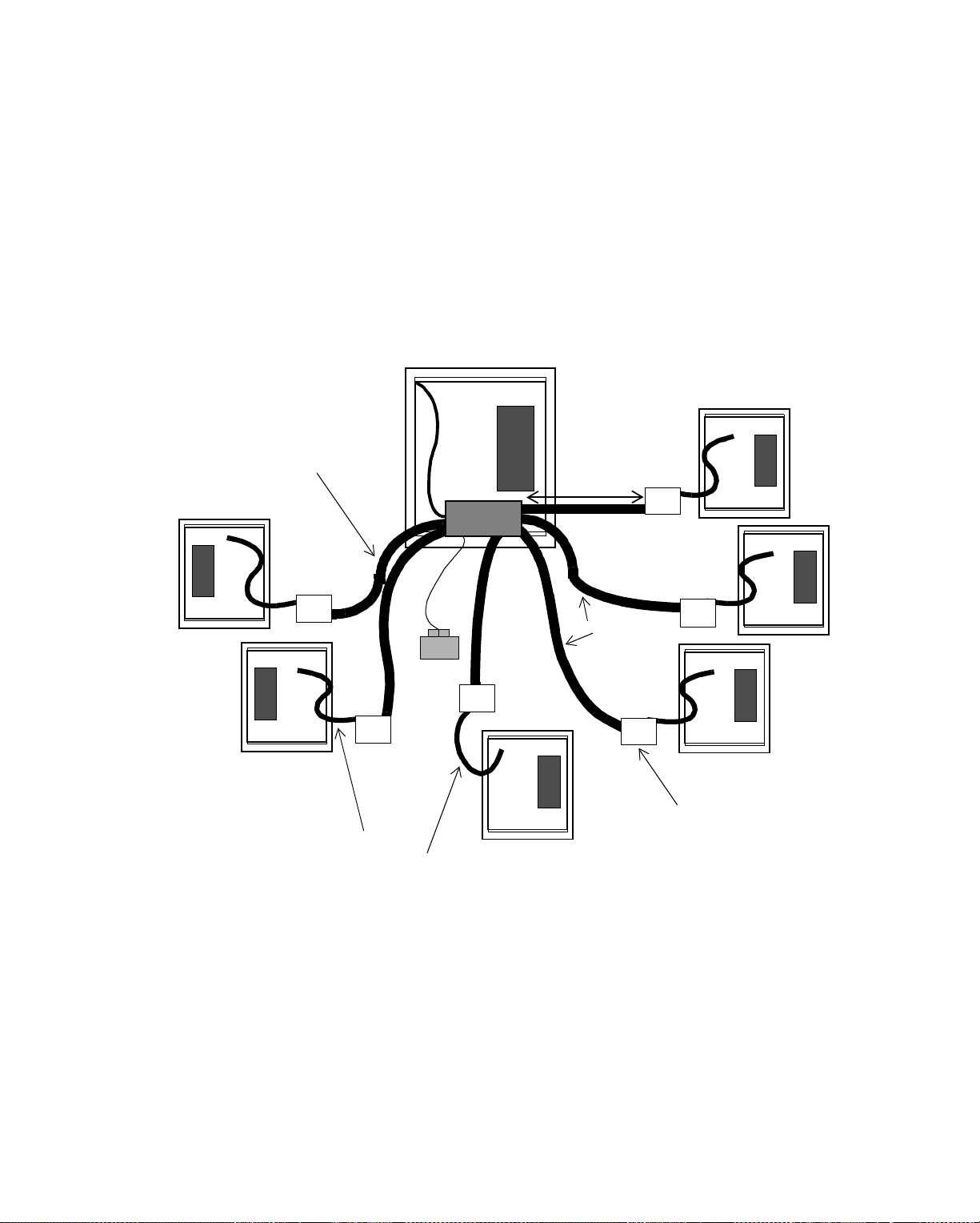
Cabling Co nf ig uration for Ethern e t
Since you can have more adaptors than hubs, you can have up to six nodes on the
star by using the adaptor and still have the option of using three more hubs
somewhere else.
Figure 5-33.shows a six-arm fiber optic star topology with one EnergyLink 2500
and several coax-to-fiber adaptor cards. In this arrangement, you have more than
four fiber optic cable ports on the hub, so you must have an external power supply
for it. (The star actually has seven arms, but the seventh is formed with coaxial
cable.)
Figure 5-33. Six-Arm Fiber Optic Star Topology Employing Coax-to-Fiber Adaptors
Fiber Optic Cable
Connecting from
EnergyLink 2500
to Adaptors
Max 6,561 ft.
(2000 m)
Fiber
Optic
Cable
Coax-to-Fiber
Coaxial Cable
Adaptor
Connecting Controllers
to Coax-to-Fiber Adaptors
To expand a small star, you could have stars on the end of each arm of the star.
How?
5-38 Andover Controls Corporation
 Loading...