

Page 1

Controlling Tomorrow’s World
EnergyLink 2000
Installation Guide
Electronic Version
Andover Controls Corporation i
Downloaded from - http://www.guardianalarms.net
Page 2

Version A
Reproduction or distribution forbidden.
Copyrigh t 1992–1996 by Andover Controls.
Subject to change without notice.
Order No. 30-3001-179
Copyright
1992–1996
Andover Controls Corporation
300 Brickstone Square
Andover, Massachusetts 01810
All Rights Reserved.
Published by the Engineering Departm ent at Andover Controls Corporation.
IMPORTANT NOTIC E
This product is subject to change without notice. This document does not constitute any warranty, express or implied. Andover Controls Corpor ation reserves the right to alte r cap ab ilities, performance , and pres en tation of this
product at any time.
ii EnergyLink 2000 Installation Guide
Page 3

Preface
EnergyLink 2000 Installatio n Guide
The
installing the EnergyLink 2000, 2100, and 2101 on EnergyNet. It first
presents how to prepare the site, including facts about proper grounding, then how to install the various EnergyLinks.
For basic information on local area networks (LANs), refer to the
presents instructions for
EnergyNet and Infinet Configuration Guide
.
Andover Controls Corporation iii
Page 4

iv EnergyLink 2000 Installation Guide
Page 5

Installing the EnergyLink 2000
EnergyNet
This manual covers installi ng the
have not planned out your network yet, read the
Configuration Guide
EnergyLink
s for your installation.
first. It contains details on how to select the best
EnergyL i nks
EnergyNet
on
EnergyNet and Infinet
. If you
Warranty Registration
Your warranty is effective for 18 months star ting on the date the
equipment is shipped.
Warning
All wiring must comply with all local , stat e, and nationa l ele ctrical
codes.
EnergyLink 2000 Installation Guide 1
Page 6

Preparing to Install EnergyLinks
Without
Acting as central active hubs, the
tributed star topology networks.
In addition,
cable length for all buses, but also increase the number of controllers allowed on a single bus. You can use
and to diagnose network problems. The
flexible and diverse.
Before you begin, you determine the exact kinds of links you require,
and the number of central hubs, cable switching links, and repeaters. If
you are not sure what you need or how to order it, read the
and Infinet Configuration Guide
Before you can install the
know some basic information about them: the types, their modu les,
their dimensions and enclosures, power requirements, grounding re-
EnergyLink
EnergyLinks
s, you can have only a bus topology
EnergyL ink
allow you to not only extend the maximum
EnergyLinks
.
EnergyLink 2000, 2100
s let you form star and dis-
to switch cable types
EnergyLink
, or
EnergyNet
family of links is
EnergyNet
2101
, you need to
.
quirements, and environmental requirem en ts .
Note
This equipment has been tested and found to comply with the limits for
a Class A digital device, pursuant to Part 15 of the FCC Rules. These
limits are designed to provide reasonable protection against harmful
interference when the equipment is operated in a commercial
environment. This equipment generates, uses, and can radiate radio
frequency energy and, if not installed and used in accordance with the
instructions in this manual, may cause harmful interference to radio
communications. Operation of this equipment in a residential area is
likely to cause harmful interference in which case the user will be
required to correct the interference at his own expense.
2 EnergyLink 2000 Insta llation Gu ide
Page 7

EnergyLink Dimensions
Each
side a hinged aluminum enclosure that meets UL standards.
The modules that you ordered with the
for either all coaxial cable, or mixed coaxial and fiber optic cable, or all
fiber optic. Each module is approximately 5.25H × 1W × 7D in.
Modules with coaxial cable ports have four ports. Modules with mixed
coaxial and fiber optic cable ports have two coaxial and two fiber optic
cable ports.
Each
are in sealed aluminum enclosures that meet UL standards.
EnergyLink 2000
EnergyLink 2100
is 5.75H × 10.43W × 8.66D in. The unit is in-
or
Power Requirements
Warning
EnergyLink 2000
2101
is 9.625H × 6.375W × 1.75D. The units
can have ports
Be sure your installation complies with local, state, and national
electrical codes.
Caution
EnergyLink 2000
The
unswitched circuit. Other
EnergyLink 2000
should receive power from its own independent,
EnergyLink
and do not require their own power source.
s are attached to a controller or
EnergyLink 2000 Installation Guide 3
Page 8
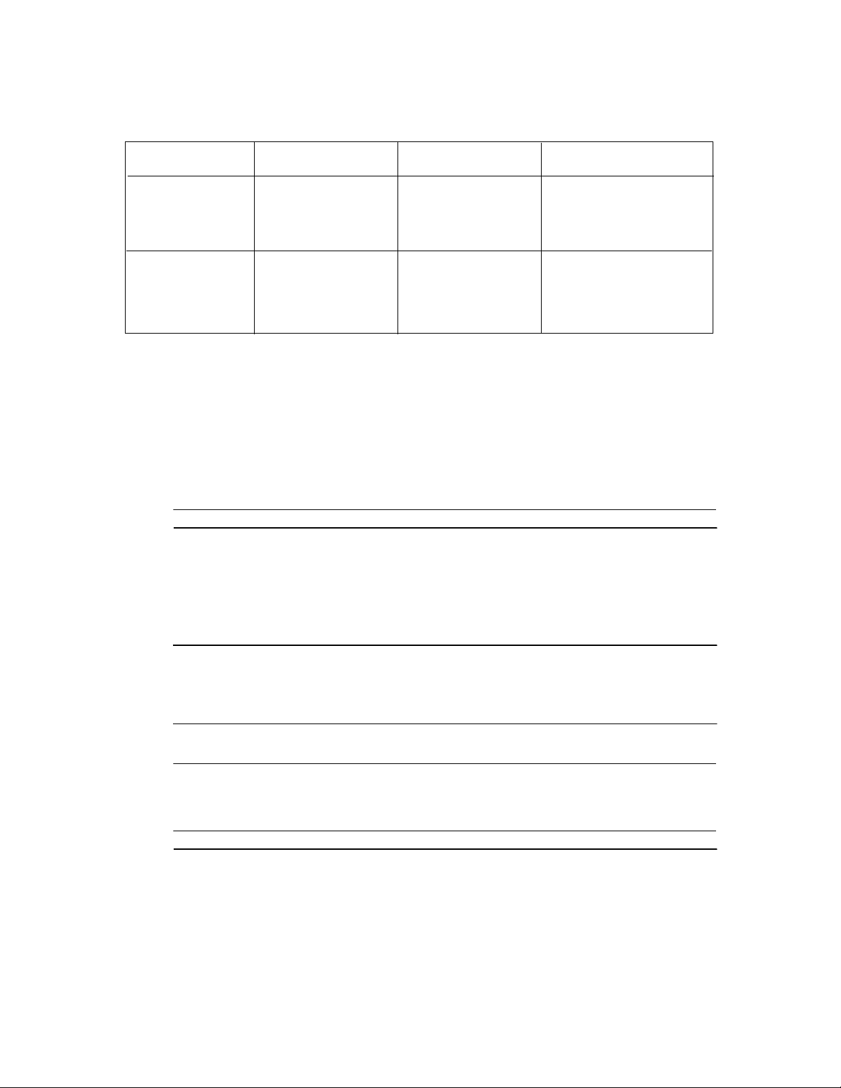
Table 1. Electrical Specifications
Location Input Power
United States 115 V +/–15%
@ 1/2 A
50-60 Hz
Europe 230 V +/–15%
@ 1/4 A
50-60Hz
Output Power Fuse Size/Rating
+5 V +/–5%
@ 3 A
50-60 Hz
+5 V +/–5%
@ 1/2 A
50-60 Hz
We ship it set to the correct setting with the correct fuse. If you want to
change the setting, follow the ins truc ti ons incl uded in the inst alla tion
information.
Building Ground Requirements
Warning
5 × 20 mm Fuse/
115 V 1 A slow
blow
5 × 20 mm Fuse/
230 V 1/2 A slow
blow
Be sure that all products from Andover Controls Corporation is
grounded to true earth ground. This kind of ground protects the
equipment from lightning strikes and other power surges in the area.
We cannot guarantee that the controller system will operate as
documented unless you properly grou nd all control lers .
Warning
Be sure to have your grounds inspected before you begin the
installation process to be sure your municipality follows the National
4 EnergyLink 2000 Insta llation Gu ide
Page 9

Electrical Code.
substandard electrical grounds.
An example of a substandard ground is a galvanized steel cold water
pipe. As the pipe corrodes, it does not act as a true ground. The corrosion acts as an insulator, raising the potential of the pipe with respect to
the ground.
When lightning strikes in the area of the ins talla tion, it drastically
changes the potential of the earth.
Surges of much lower potential also impact the reliability of Andover
Controls equipment.
Since properly grounded Andover Controls units respond to changes in
Many muni cipa lities do not an d often have
potential more rapidly than poorly grounded electrical systems, a poorly grounded building tries to reach ground through the Andover
Controls system. The surge of current can destroy electronic components on the controller board.
Inspecting the Ground
You can check your ground as follows:
1. Check your ground by first inspecting the building power
distribution panel for earth ground termination. If the ground
termination is any of the following, it is not adequate and must be
corrected:
• Does not exist.
• Is connected to a corroded or galvanized pipe.
• Is connected using a small gauge wire (smaller than 14 AWG).
2. If your
be sure your
conductor that terminates at the distribution panel.
EnergyLink 2000 Installation Guide 5
EnergyLink
EnergyLink
will not be mounted inside an
is connected to the ground with a copper
9000
controller,
Page 10

Environmental Requirements
EnergyLinks
The
to 140° F and with humidity between 10 and 95%, non-condens ing.
operate in rooms with temperatures ranging from 32
6 EnergyLink 2000 Insta llation Gu ide
Page 11

Preparing Coaxial Cables
Each length of coaxial cable connecting to a controller, workstation,
EnergyLink 2000, EnergyLink 2100
BNC male connector at both ends. If the cables are not already prepared, you prepare them by attaching the male connectors.
Figure 1 shows a single piece of prepared coaxial
Each piece of coaxial cable from male connector to male connector
must be at least 6 ft long.
EnergyLink 2101
, or
must have a
EnergyNet
cable.
Figure 1. EnergyNet Coaxial Cable
6 ft minimum
Male Connectors
on either end of Coaxial Cable
—One end connects to the
the other to a controller or workstation
EnergyLink
,
Figure 2 shows the
Model # 2070). Do not use T connectors on the
EnergyNet
coaxial T connector (Andover Controls
EnergyLink 2000
ports.
Figure 2. EnergyNet Coaxial T Connector
Coaxial Cable
Never
EnergyLink 2000 Installation Guide 7
connects to an EnergyLink
Coaxial Cable
Page 12

Installing the EnergyLink 2000
Unpacking
Be careful when unpacking the unit to not damage the packaging
material—you must reuse it if you ship the produ ct back for repair.
Parts Required
•
1 or 2
• Modules
(Andover Controls Model No. 2001 has 4 coaxial ports,
Model No. 2002 has 2 coaxial and 2 fiber optic, Model No. 2003 has
4 fiber optic ports)
• Prepared Coaxial Cables
• Coaxial Cable
• BNC Connectors for Coaxial Cable
• Fiber Optic Cable with ST Connectors (Bayonet Style) (optional)
EnergyLink 2000
s
Setting the Input Voltage
Usually your
voltage (115 V or 230 V). If the input voltage is not correct, you can
switch it from one to the other by changing the position of a jumper
inside the hub. To change the jumper position, proceed as follows:
EnergyLink 2000
is shipped preset to the correct input
Warning
Be sure you disconnect the
before you remove the input voltage jumper.
1. Disconnect the
8 EnergyLink 2000 Insta llation Gu ide
EnergyLink 2000
EnergyLink 2000
from the AC power source.
from the AC power source
Page 13

2. Look at the sides of the
EnergyLink 2000
. Notice that three scr ews
are on each side. Remove all six screws.
3. Slide the top of the enclosure up and off the unit.
4. Position the
EnergyLi nk 2000
on its left side so the front is facing you.
5. Inside, find the jumper wire to the right of the heat sink. It is labeled
P3 on the printed circuit board.
Figure 3 shows the jumper positions for 115 V and 230 V with the
EnergyLink 2000
front facing you.
Figure 3. Setting of the EnergyLink 2000 Input Voltage Jumper for
115 V or 230 V, Front Top View
115 V Position
115
230
P3
230 V Position
115
230
P3
Exposed Pin
Below Jumper
Pins When
Jumper
Exposed Pin
Above Jumper
Removed
6. To switch from 115 V to 230 V, remove the jumper and move it
down one pin. Placing the jumper in the 230 V position effectively
disconnects it, but keeps it in a safe pl ace if you ever want to switch
back.
To switch from 230 V to 115 V, remove the jumper and move it up
one pin.
7. Check to be sure you have the correct fuse. The fuse is on the far
right side of the printed circuit board in approximately the verti cal
center.
EnergyLink 2000 Installation Guide 9
Page 14

Figure 4 shows the location of the input power fuse.
Figure 4. Location of EnergyLink 2000 Input Power Fu se, Front
Right Side View of Printed Circuit Board
Heat
Sink
Input
Jumper
Power
Fuse
8. If switching from 115 V to 230 V, replace the fuse with a 5 × 20 mm
230 V 1/2 A slow blow fuse.
If switching from 230 V to 115 V, replace the fuse with a 5 × 20 mm
115 V 1 A slow blow fuse.
10 EnergyLink 2000 Installation Guide
Page 15

Installing the Modules
Before you proceed, you must install the modules in the
2000.
metal front piece. The four ports are on the metal front.
The modul es each sli de into one of th e four slot s on the
Figure 5 shows the module slots on the
and bottom of each slot is a groove, shown in the close-up on the slot.
Each module is a printed circuit board “card” attached to a flat
EnergyLink 2000.
Figure 5. Module Slots on EnergyLink 2000
Grooves
EnergyLink
EnergyLin k 2000
Along the top
.
Openings (Slots) Wh ere
You Insert Modules
EnergyLink 2000 Installation Guide 11
Page 16

Figure 6 shows a module.
Figure 6. An EnergyLink 2000 Module
Permanently
Attached
Screws
Each module has permanently attached screws at the top and bottom.
To insert a module, carry out the following steps:
1. Insert the module printed circuit board “card” in the groove of the
module opening.
2. Slide the card all the way in.
3. Tighten the top and bottom screws by hand.
4. If you want the module held more tightly, use a flathead screwdriver
to more firmly tighten the module’s screws.
12 EnergyLink 2000 Installation Guide
Page 17

Mounting
You can choose to mount a single
one on top the other. Proceed as follows:
EnergyLink 2000
or several of them,
Warning
Never drill holes in the
A metal shaving could easily short circuit the electronics.
1. Insert four screws in the wall in positions for the two eyelets and two
screw holes in the side tab of the
Figure 7 shows the location of the four
2. Hang the unit on the screws and screw the unit dir ec tly to the wal l.
EnergyLink 2000
EnergyLink 2000
cabinet or any of the modules.
.
EnergyLink
four eyelets.
3. If you are installing multiple hubs, cascaded, one on top the other,
place the second on top of the first and screw it to the wall.
4. Repeat step 3 until you have cascaded the number of hubs you need.
(You can stack up to eight hubs.) See the section called Cascading
EnergyLinks
for information on how to run the cables.
EnergyLink 2000 Installation Guide 13
Page 18

Figure 7. Locations of Screw Holes to Mount EnergyLink 2000
Back of
EnergyLink 2000
.5 in. holes, 4 places
(see Detail)
Enclosure
10.43 in.
9.53 in.
.34
2.08 in.
5.75 in.
3.0 in.
.84 in.
.22
.50
Detail
(4 places)
.86 in.
14 EnergyLink 2000 Installation Guide
Page 19

Connecting Controllers and Workstations to EnergyLink 2000
To connect the controllers and workstations to the
proceed as follows:
1. Connect the coaxial
workstations.
2. Run the unconnected ends of the cables up to the hub.
Coaxial Cable
Fasten the open end of the cable to the coaxial cable port on the front
panel of the
1. Attach a straight BNC connector to the cable.
2. Insert the end of the connector into the port.
EnergyLink 2000
Fiber Optic Cable
EnergyNet
as follows:
EnergyLink 2000
cables to the controlle rs an d
,
Notice that the open end of the fiber optic cable has two ST connectors.
You connect them to a fiber optic port on the front panel of the
EnergyLink 2000
1. Unscrew the plastic caps from the first pair of ports.
2. Insert the bayonet-style ends into each port.
On a fiber optic cable module or a mixed module, you must use the
first two adjacent fiber optic ports for the first cable and the second
two adjacent ports for the next cable.
as fol low s:
EnergyLink 2000 Installation Guide 15
Page 20

Installing the Energy Link 2100 or 2101
Unpacking
Be careful when unpacking the unit to not damage the packaging
material—you must reuse it if you ship the produ ct back for repair.
Parts Required
• EnergyLink 2100
• One Metal Plate (included with
• Four No. 6 Screws (included with
• 1-ft coaxial cabl e wit h att enu ator (included with
• Prepared Coaxial Cables
• BNC Connectors for Coaxial Cable Ports
• Fiber Optic Cable with ST Connectors (Bayonet-Style) (optional)
or
2101
s
EnergyLink
EnergyLink
Mounting EnergyLink 2100 or 2101 Inside a 9000 Controller
You can install an
controller.
Figure 8 shows the positioning of the modem and
inside of the
mount the plate that comes with
9000
EnergyLink 2100
controller’s door. (If you have no modem, you must
EnergyLink
or
2101
inside the door of a
and then mount the
)
)
EnergyLink
EnergyLink
)
9000
on the
EnergyLink
16 EnergyLink 2000 Installation Guide
on it.)
Page 21

Figure 8. Position of EnergyLink 2100 (or 2101) Mounted Insi de
9000 Controller Front Door, Side View
9000
Door
EnergyLink 2100
Mounting Plate
Modem (Optional)
Is Here
EnergyLink 2000 Installation Guide 17
Page 22

To mount the link on the door, proceed as follows:
1. Open the
9000
controller cabinet and look on the inside front door
to the lower right. Notice the three st an doff s. Posi tion the me tal
plate so the screw holes in it align with those on the standoffs.
2. Screw the metal plate secur ely to the stand offs using three No. 6
Phillips screws.
3. Notice that the metal plate has three metal studs only about 1/8 in.
high.
Figure 9 shows the studs.
Figure 9. EnergyLink 2100 (or 2101), Back View
EYELET
EYELET
SCREW HOLE
4. Look at the back side of the
EnergyLink
EYELET
. In three corners you see
eyelets. In the fourth, you see a screw hole.
5. Put the
EnergyLink
on the plate so the largest ends of the three
eyelets each go over one of the metal studs.
18 EnergyLink 2000 Installation Guide
Page 23

6. Gently pull the
EnergyLink
down as far as it can move. Now the
screw hole on the lower right front should line up with the hole in
the metal plate.
7. Insert the No. 6 Phillips screw in the hole and tighten it.
8. Look at the 1-ft coaxial cable. Notice that one end has the usual
BNC connector and the other end has a longer piece. This longer
piece is an attenuator to make up for the cable being less than the
minimum length required (3 ft).
9. Connect the end of the 1-ft coaxial cable with the attenuator to the
coaxial port on the
to the ENL PWR coaxial connector on the
Figure 10 shows the
EnergyLink
and the end with the BNC connector
EnergyLink 2101
9000
controller.
completely ins talled.
Figure 10. Installed EnergyLink 2100 (or 2101), Front View
Fiber Optic Port
Coaxial Port
14
2 3
ENERGYLINK
ACTIVITY 4
ACTIVITY 3
ACTIVITY 2
ACTIVITY 1
RECONFIG
TIMING
Mounting Plate
Screw To Tighten
EnergyLink 2000 Installation Guide 19
Page 24

EnergyLink 2100
The
power supply so you need not connect it to a power supply.
or
2101
uses power from the
9000
controller
Now connect the various cables to the ports on the
Cascading EnergyLinks
You can cascade
to an open port on each one.
Figure 11 shows three cascaded
Figure 11. Stacked EnergyLink 2000 Hubs Cascaded with
Coaxial Cable
EnergyLink
s by connecting a prepared coaxial cable
EnergyLink 2000
EnergyLink
hubs.
.
Coaxial
Cable
Stacking
you can have connected in one area.
You can also cascade and stack other members of the
family, but when you do, you reduce their already limited number of
ports, so they are not as practical a choice for connecting multiple stars.
EnergyLink 2000
s dramatically increases the number of nodes
EnergyLink 2000
20 EnergyLink 2000 Installation Guide
Page 25

Extending a Bus with an EnergyLink
To increase the number of feet of coaxial cable between two controllers,
you use an
EnergyLink 2100
or
2101
, as follows:
Caution
Remember that every
Each one reduces the total number of workstations and controllers you
can have on the network.
1. Disconnect one male end of a connected coaxial cable from the last
controller and connect it to the first open port of the
2. Connect the end of a new prepared coaxial cable to a second open
port of the
EnergyLink
EnergyLink
.
counts as a node on the network.
EnergyLink
.
Figure 12 shows how the
EnergyLink
connection looks.
EnergyLink 2000 Installation Guide 21
Page 26

Figure 12. Connecting an EnergyLink 2100 to Extend a Bus
EnergyLink 2100
First
Coaxial
Cable
Second
T Connector for
Workstation with
Coaxial
Cable
PS/2 Card
Connect to the
Next Controller
on the N etwork
3. Connect the new coaxial cable to the next controller or workstation
on the network.
4. Be sure that workstation is properly terminated if it is at the end of
the bus.
22 EnergyLink 2000 Installation Guide
Page 27

Powering Up the EnergyLink 2000
Turn on the power to the
switch located on the lower right corner of the front panel. The unit
starts operating immediately.
Once the
are installing or removing modules from it. You may connect and disconnect cables at ports without any damage to the
without affecting
EnergyLink 2000
EnergyNet
EnergyLink 2000
is on, we recommend it be left on unless you
operation.
Understanding the LEDs
EnergyLink 2000
to each port. The LEDs to the right of the rightmost module are for timing and re-configuration. Here’s how each LED responds:
TIMING—The timing light blinks to indicate
and transmitting signals.
RECON—The reconfiguration light turns on briefly when you start up
EnergyLink 2000
the
also has LED lights on its front panel that correspond
. It indicates that the network is being configured.
by depressing the power
EnergyLink 2000
EnergyNet
is receiving
and
Other than at power up, the network re-configures itself only when you
remove a node, so this light should remain off most of the time.
+PWR and –PWR—These lights indicate power is being supplied to the
EnergyLink 2000
are on.
All modules have activity li ghts, one associ ated with each port. Her e’s
how each LED responds:
ACTIVITY—Each activity LED blinks to indicate that its port is re-
ceiving and transmitting data. The LED blinks in a pulsing fashion as
long as the unit is operating properly.
If you run into problems with the network after powering up the
EnergyLink 2000,
Guide
.
. As long as the unit is operating properly, these lights
refer to the
EnergyNet and Infinet Configuration
EnergyLink 2000 Installation Guide 23
Page 28

Powering Up the EnergyLink 2100 or 2101
EnergyLink 2100
The
troller’s power supply.
Once you connect the power to the
installation guide, the
immediately.
2101
and
EnergyLink 2100 or 2101
Understanding the LEDs
Below is how the
9000
ACTIVITY—The activity LEDs blink to indicate that the corresponding port (ports are numbered left to right, 1 through 4) is receiving and
transmitting data. So they blink in a pulsing fashion as long as the unit
is operating properly.
TIMING—The timing light blinks to indicate
and transmitting signals.
controller is powered up:
EnergyLink 2100 or 2101
both receive power from a
9000
controller as instructed in the
starts operating
LEDs respond once the
EnergyNet
is receiving
9000
con-
RECONFIG—The reconfiguration light turns on briefly after you power up. It indicates that the network is being configured. Other than at
power up, the network reconfigures itself only when you remove a
node, so this light should remain off mo st of the time.
If you run into problems with the network after powering up a unit with
EnergyLink 2100
an
Configuration Guide
or
.
2101,
refer to the
EnergyNet and Infinet
24 EnergyLink 2000 Installation Guide
 Loading...