

Page 1

Controlling Tomorrow’s World
EMX34/CK34 Cardkey Interface
Board Installation Guide
The EMX34/CK34 Cardkey Interface B oard is designed t o convert the signals fr om up to
Cardkey Model # L47 readers (o r
Wiegand format , which can be read by the AC X 700/780 famil y of controllers .
Warran ty R egist ratio n
Your warranty is effective for 18 months starting on the date the system is shipped.
two
Model #L40- 6 readers, which dr aw more cur rent) into
four
Site/System Setup Requirem ents
Before yo u ins t all the contr oller, you sho uld map out w here you pla n t o install each int erface. Whe n planning th e s it es , be aware of dim ensions , power requ irements, and
environm ental requ irements.
Dime nsions
The EMX 34 printed circ uit board is app rox imately 6. 125 × 3.625” (160 × 92 m m ).
Power Requirements
The EMX 34 receives power from an ACX 700/780 to supply the Cardkey reader. The EMX
34 requires an additional 24 VAC (1 amp) which powers the Cardkey reader incandescent
lamps (LE D s ). Th e EMX 34 boa rd converts t he power t o 9 VD C output for th e lam ps.
Environmental Requirements
The EMX 34 operates in the same environment as any Infinet controller.
Downloaded from - http://www.guardianalarms.net
EMX 34 Installation Guide 1
Page 2

Version A
Reproduction or distribution forbidd en.
Copyrigh t 1992–1996 by Andover Controls.
Subject to change without notice.
Order No. 30-3001-494
Copyright
1992–1996
Andover Controls Corporation
300 Brickstone Square
Andover, Massachusetts 01810 USA
All Rights Reserved.
Published by the Engineering Departm ent at Andover Controls Corporation.
IMPORTANT NOTICE
This product is subject to change without notice. This document does not
constitute any warranty, express or implied. Andover Controls C orpor ation
reserves the right to alter capabilities, performance, and presentation of this
product at any time.
EMX 34 Installation Guide 2
Page 3

Parts Included and Required
Unpacking
When unpacking the unit, do not damage the packaging material—you must reuse it if you
ship the pro duct back fo r repair.
Parts Included with the EMX 34
• EMX 34 Printed Circu it Board
• Two Plastic PCB Mounting Brackets
• Two Plastic DIN Rail Mounting Brackets
• Hardware Installation Guide (this manual)
Additional Items Required
• An ACX 700 or 780 Family Contro ller
• Cardkey Readers
• An Extra Cable and Female Molex Connector per Reader
• AC Powe r C able
• Output Wires
• Two End Clamps
• DIN Rail
• Enclosure
EMX 34 Installation Guide 3
Page 4
Mechanical Installation
The EMX 34 is designed to be mounted to a DIN rail within an enclosure.
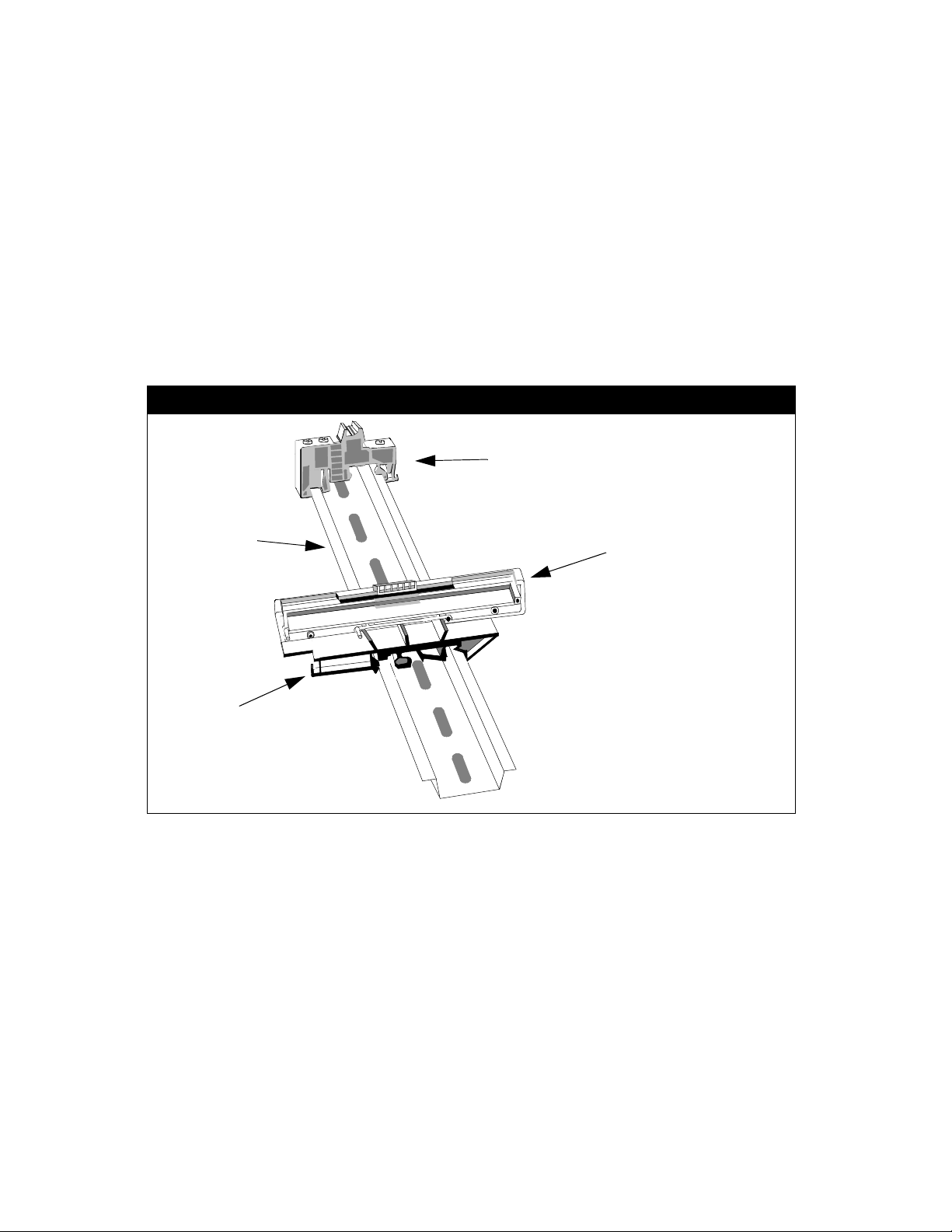
Mounting the EMX 34 to a DIN Rail
Refer to the illustrations for more details on the parts involved in the mounting procedure.
1. Slide an e nd clamp ont o t he DIN Rail. Tighten the screws when the clamp is in the
position des ired.
Assembling M ounting Bracke ts to DIN Rail
End Clamp
DIN Rail
DIN Rail
Mounting Bracket
PCB Mounting Bracket
2. Slide a DIN Rail mounting bracket under the PCB bracket until flush on the back side.
3. Slide the DIN Rail mounting bracket with PCB bracket (b ack/flat side fi rst) onto the DIN
Rail. Position the flat side up against the end clamp.
EMX 34 Installation Guide 4
Page 5

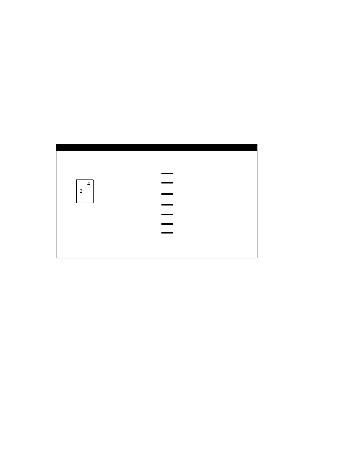
4. Insert the top of th e printed circ uit board into the PCB brac k et.
Attaching the PCB to B rackets
DIN
DIN Rail
End Clamp
Top of PCB
P1
–
+
5VDC
F1
LED
LED
PWR
DATA
RED
LED
GREEN
P2
GND
5VDC
LED
LED
PWR
DATA
RED
LED
GREEN
P4
GND
5VDC
LED
LED
PWR
RED
LED
GREEN
P6
DATA
GND
5VDC
PWR
RED
LED
P8
C 1993
5VDC
P3
1
LED
P5
∅
LED
GND
5VDC
P7
1
∅
LED
GND
5VDC
P9
1
∅
LED
GND
5VDC
DIN Rail Mounting Bracket
PCB Mounting Bracket
LED
LED
GND
DATA
GREEN
MADE IN USA BY ANDOVER CONTROLS 05-1000-793 EMX34 REV A
1
∅
GND
5. Slide the ot her DIN Rail m ounting bra c k et ont o the rem aining PCB brac k et.
6. Slide th e DIN Rail b r ack et and PCB bra cket o nto the DIN Rail, flat side last. Carefully
slide the ass embled br ac k et s onto the bot to m of th e printed ci rc uit board until tight.
7. Slide another end clamp onto the DIN Rail. Position it up against the flat side of the
brackets.
8. Tighten the end clamp screws to se c ure.
EMX 34 Installation Guide 5
Page 6

Wiring the EMX 34
The EMX 34 m us t be connect ed to an ACX 700/780 f am ily control ler, t o an AC power
source, and to a Cardk ey reader.
The schematic to th e right repre se nt s th e data
conversion action of the EMX 34. Data flows
from the Cardkey reader to the ACX 700/780,
and is con v erted into W iegand format. The C ardkey
reader ’s lam ps are switc hed ON or OF F as a f unction
of the sta tu s of the AC X controller’s LEDs.
The same wiring sc hematic app lies to each of the
four channels.
Note: In this schematic, data conversion is
represented from lef t to right, which is not
the same direction as t he physica l board.
Data Conversion
Cardkey Reader ACX 700/780
Channel 1
Data
DATA
LED
LED
(same as above)
(same as above)
(same as above)
Converter
Lamp
Driver
Channel 2
Data
Converter
DATA
LED
LED
Lamp
Driver
Channe l 3
Data
Converter
DATA
LED
LED
Lamp
Driver
Channel 4
Data
Converter
DATA
LED
LED
Lamp
Driver
LED
LED
∅
1
∅
1
LED
∅
1
∅
1
LED
Warning
Be sure that all equipment is not receiving electrical power while you are wiring the controller, or
you could receive an electrical shock that is life-threatening.
Warning
Be sure that wiring and installations comply with local, state, and national electrical codes.
Refer to the fi gure of the print ed circuit bo ard.
The EMX 34 printed circ uit board has four inputs (P2, P4, P6, P 8) and four ou tp ut s (P3,
P5, P7, P9 ). Th e inputs from t he Cardkey reader are wi red on the righ t -hand side of t he
physical board, and th e outputs on the lef t -hand side.
EMX 34 Installation Guide 6
Page 7

EMX 34 Printed Circuit Board
24 VAC
Power
Connection
Outputs*
(to ACX)
+
–
P1
F1
P2
5VDC
LED
1
∅
GND
5VDC
LED
1
∅
GND
5VDC
LED
1
∅
GND
5VDC
LED
1
∅
GND
MADE IN USA BY ANDOVER CONTROLS 05-1000-793 EMX34 REV A
P3
P5
P7
P9
C 1993
P4
P6
P8
5VDC
LED
PWR
RED
LED
GREEN
LED
DATA
GND
5VDC
LED
PWR
RED
LED
GREEN
LED
DATA
GND
5VDC
LED
PWR
RED
LED
GREEN
LED
DATA
GND
5VDC
LED
PWR
RED
LED
GREEN
LED
DATA
GND
1 amp picofuse
P2/P3 = Channe l 1
P4/P5 = Channe l 2
Inputs
(from Cardkey readers)
P6/P7 = Channe l 3
P8/P9 = Channe l 4
*Please note that on the REV A board, ø and 1 outputs are incorrectly marked (switched).
This drawing refl ects the REV A board.
The EMX 34 conv erts the Cardk ey input data into W iegand format, which can be read by
the ACX 700/780 controllers. The dotted-line arrows in the EMX 34 PCB figure indicate the
flow of data fr om t he inputs to the outputs.
EMX 34 Installation Guide 7
Page 8

Wiring the EMX34 to an ACX Controller
1. Locate the Wiegand out puts, alon g t he left-han d s ide of the EM X 34 printed cir cu it
board (P3 , P 5, P7 P9). Each output inclu des five co nnections .
Note that o n t he R EV A board, t he 1 and Ø terminals are la beled incorrectly.
Wiring the EMX 34 to an ACX 700/780
ACX 700/780 EMX 34
+5V
LED
1/DATA
0/CLK
GND
5VDC
LED
(1 on rev A)
∅
1 (∅ on rev A)
GND
2. Strip the end of an 18 AWG wire. Insert it into the appropriate terminal block connector
accordin g t o t he diagram and tighten th e s c rew .
3. Repeat this procedur e f or t he remaining four wires.
Wiring AC Power to the EMX 34
1. Locate the terminal labeled P1 in the upper left-hand corner of the printed circuit board.
2. Connect t he stripped ends of a 24 VAC (±20% ) external power su pply to the
appropr iate terminals and tighte n th e s c rew s.
Should you need to re place the 1 am p s oc k et picofuse, it is located at F1 on th e printed
circuit board.
EMX 34 Installation Guide 8
Page 9

Wiring the Cardkey Reader to the EMX 34 Interface Board
Each Cardkey input on th e EMX34 takes 6 wi res. Ther e are four inp uts, locate d along th e
right-hand side of the printed circu it board (P2, P4 , P6, and P8).
1. Locate the existing g ray c able on the ba c k sid e of the Card ke y reader. Str ip t he end
of the cable t o ex pose the w ires.
2. Strip the ends of the black, white and red wires.
3. Followin g th e w iring diagram below, place the ap propriate wir es int o the correc t
terminals and tighten the screws. Insert the shield into the GND terminal.
Wiring the EMX 34 to the Ca rdkey Reader and LED s
EMX 34 PCB
(6)
(5)
P2
(4)
(3)
(2)
(1)
5VDC
LED
PWR
RED
LED
GREEN
LED
DATA
GND
5VDC
LED
PWR
extra cable (for LEDs)
Black
Red
White
Shield
Red
White
Black
Shield
existing ca ble (for read er)
Molex
Connector
Cardkey Reader
EMX 34 Installation Guide 9
Page 10
Wiring the LEDs to the EMX 34
1. Locate the plasti c Molex connector with the four white wires on the back of the Cardkey
reader.
One wire is connected to male pin 4 and one to pin 5, and two wires are connected to
pin 3. Pin num bers 3, 4, an d 5 power the LEDs.
2. O bta in a sup pl emen tar y C ard ke y c able , n umb er 9130 02/ A71 5 st y le 20 95 300V wit h a
female Molex connector attached.
If you need to wire the female Molex connector, follow the figure below.
Molex Connector Pinouts
Molex Connector
on Cardkey Reader
1
4
25
36
Note: The EMX 34 pin number s correspond to the screws on the EMX 34 printed circu it board.
EMX 34 Cardke y Unit
5VDC (pin6)
LED
PWR (pin 5)
RED
LED (pin 4)
GREEN
LED (pin 3)
DATA (pin 2)
GND (pin 1) BLACK (GND )
GND (pin 1)
RED (5 VDC)
Molex pin 3 (LED PWR)
Molex pi n 5 (RED LED)
Molex pi n 4 (G RN LE D)
WHITE (DATA)
SHIELD (GND)
Pins 3, 4, and 5 are the on ly pins required in the connector. From th e ex tra cable, the
black wire is c onnected to pin 3, the white w ire to pin 4 and the red to pin 5.
3. Plug the M olex connec t or into the one on the bac k of the C ardkey reader.
4. Strip the other end of the supplementary Ca rdk ey cable to ex pose the wir es .
5. Strip the ends of the black, white, and red wires.
6. Followin g th e t w o precedin g f igures, plac e t he appropriate wires into the corr ec t
terminal s a nd t ighten the s cr ew s .
EMX 34 Installation Guide 10
Page 11

Powering Up the EM X34
1. Be sure the 24 VAC power source is wi red proper ly ; b e s ure all three wires are
connected.
2. Turn on the AC power sourc e (or close th e c onnectio n) and the interface start s
automatically.
Troubleshooting
For information on how to assign point numbers and program the outputs, see the SX 8000
Programm er’s Guid e or t he Andove r C ontrols
If you have problems with the Infinet controller after installing the module, see the ACX 700
or 780 Installation Gu ide, and the
Infinity
Infinity
Network Co nf iguration Guide.
CX Programmer’s Guide.
EMX 34 Installation Guide 11
 Loading...