

Page 1

DCX 250
Installation Guide
Andover Controls Corporation i
Downloaded from - http://www.guardianalarms.net
Page 2

Version F
Reproduction or distribution forbidden .
Copyright 1997 by Andover Controls.
Subject to change without notice.
Order No. 30-3001-196
Copyright
1997
Andover Controls Corporation
300 Brickstone Square
Andover, Massachusetts 01810
All Rights Reserved.
Published by the Engineering Departm ent at Andover Controls Corporation.
IMPORTANT NOTICE
This product is subject to change without notice. This document does not constitute any warranty, express or implied. Andover Controls Corpor ation reserves the right to alte r cap ab ilities, performanc e, and pres e ntation of this
product at any time.
ii DCX 250 Installation Guide
Page 3

Preface
The DCX 250 Ins tallati on Guide pres ents instructions for installing
the DCX 250 on Infinet. It first presents site preparation information
and then step-by-step installation instructions.
This manual does not include programming infor mation. For how to
program the DCX 250, see the Andover Controls Infinity CX
Programmer’s Guide.
We recommend you read the Infinity Network Configuration Guide to
plan your entire network before installing a single controller.
Andover Controls Corporation iii
Page 4

iv DCX 250 Installation Guide
Page 5

Contents
Setting Up the DCX 250
Site/System Setup Requirements .............................................................2
Cabinet Dimensi o n s an d Weig ht .................. .......... ......... ......... .....3
Power Requirements ......................................................................3
Cable Limitations . ..... .... ... ..... .. ..... .... ... ...... . ..... .. ..... .... ... ...... . ....... .. .3
Lightning Protection ......................................................................4
Building Ground Requirements .....................................................4
Inspecting the Ground ....................................................................5
Environmental Requir em en ts ....... ................ ........................ .........5
Laying Out the Site Setup ..............................................................6
Installing the DCX 250 ............................................................................7
Unpacking ........... ......... ........................ ....................... ................. ..7
Parts Requir ed ........................ ....................... ........................ .........7
Mounting ............. ....................... ........................ ....................... .....7
Connecting the AC Power Cable to the Power Supply . ....... ....... .. 9
Connecting the Infinet .................................................................11
Wiring the Infinet to the Infinity CX 9000 .................................. 13
Powering U p/ Ad justing the Con tr o l ler .............. ........................ ............14
Connecting the Battery ................................................................14
Powering U p ....... ....................... ................. ....................... ..........14
Andover Controls Corporation v
Page 6

Checking That Controller Is Operating .......................................1 5
Reset Button ................... ........................ ........................ ..............16
Adjusting the LCD View Angle ..................................................1 6
Connecting the Andover Controls Service Tool .................. ....... .1 8
vi DCX 250 Installation Guide
Page 7

Figures
Figure 1. Tag That Identifies the Controller ...............................................6
Figure 2. Dimensions of DCX 250 Cabinet, Top View..............................7
Figure 3. Dimensions of DCX 250 Cabinet, Front View ........................8
Figure 4. Location of AC Power Connection, Inside DCX 250 Cabinet ...10
Figure 5. Metal Plate and Screw for Power Supply Wire .....................11
Figure 6. Location of Infinet Connection, Inside DCX 250 Cabinet .......12
Figure 7. Infinet Cable Wiring ..................................................................13
Figure 8. Locati on of Battery , Indicator Li gh ts , and Rese t B utton,
Inside, on Back of DCX 250 Display .......................................15
Figure 9. L ocation of L C D View Angle Adjustment, Inside ,
on Back of DCX 250 Display ...................................................17
Figure 10. Location of Service Port, Inside DCX 250 Cabinet .................18
Andover Controls Corporation vii
Page 8

viii DCX 250 Installation Guide
Page 9

Setting Up the DCX 250
This manual covers the following:
• Site/System Setup Requirement s
• Installing the DCX 250
• Powering Up/Adjusting the Contro ller
This manual does not include programming infor mation. For how to
program the DCX 250, see the Andover Controls Infinity Controller
Programmer’s Guide.
Warranty Registration
Your warranty is effective for 18 months starting on the date the system
is shipped.
Warning
Be sure wiring and installations comply with local, state, and national
electrical codes.
DCX 250 Installation Guide 1
Page 10

Hardware Instal lation
Site/System Setup Requirements
Before you proceed to install the system, you should map out where you
p l a n t o i n s ta l l e ac h c o n t r o l l e r , t e r m i n a l / w o r k s t a t i o n , a n d m o d e m . W h e n
planning the sites, be aware of any electrical interference that may occur. You also need to be aware of cabinet dimensions, power
requirements, cable limitations, an d environm ental requir e ments .
Warning
This equi pment ha s bee n tested and foun d to compl y with th e limi ts for a
Class A d igital de vice, purs uant to Par t 15 of the FC C Rules. T hese limits
are designed to provide reasonable protection against harmful
inter f erence when the equi pment is operated in a commercial
environme nt. This equipment ge nerates, us e s , a nd can radia te radio
frequency energy and, if not installed and used in accordance with the
instruc tions in this manual, may c ause harmful interference to radio
communications. Operatio n of this equipment in a residential area i s
likely to cause har mful interferen c e i n w hic h case the user will be
required to c o rre ct the interference a t his own expense.
Note
This digital apparatus does not exceed the Class A limits for radio noise
emissions from digital apparatus set out in the Radio Interference
Regulations of the Canadian Department of Communications.
Avis
Le présent appareil numérique n’émet pas de bruits radioélectriq ues
dépassant les limites applicables aux appareils numériques de la class A
prescrites dans le Règlement sur le brouillage radioélectrique édicté par
le ministère des Communications du Canada.
2 DCX 250 Installation Guide
Page 11

Hardware Installation
Cabinet Dimensions and Weight
Each DCX 250 cabinet (if it has a cabinet) is approximately 8.1 × 8.1 ×
3.5 in. and weighs 8.5 lbs.
Power Requirements
Caution
If the DCX 250 is in its own cabinet, it should receive power from its
own independent, unswitched circuit.
The DCX 250 operates on 24 VA C +/–20% 50 or 60 Hz (for smoke co n-
trol applications, 24 VAC +1 0/–15%, 60 Hz). The DCX 250 consumes
up to 18 VA of power.
Cabl e Limitations
The maximum cable length for Infinet is 4,000 ft at 19,200 baud (up to
32 Infinet controllers). You can extend Infinet beyond 4,000 ft or put
more than 32 Infinet contr ollers on less than 4,00 0 ft by using the In-
fiLink 200 amplification module.
Cables that form Infinet are 24-gauge, single-twis ted-pair , tin ned,
shielded copper wire. Use the following cables1 or their equivalents:
Note
You mu s t use s hie ld ed ca bl es f o r Infinet to ensure compliance with the
Class A FCC limits and to communicate reliably.
• Brand Rex # H 9002 (single-pair)
• Anixter # 9J2401021 (single-pair plenum cable)
The cable should have a nominal impedance of 100 Ohms and a
nominal velocity of propagation of 78%.
1. You can also use any cables you may already have in place for ACNET or LBUS.
DCX 250 Installation Guide 3
Page 12

Capacitance of Infinet cable should be nominal, below 12.5 pF/ft between conductors and below 22 pF/ft between the conductor connected
to ground and the next conductor.
Lightning Protection
Warning
When running cables between buildings you must install lightning
arreste rs for Infinet to prevent electromagnetic disturbances.
Use lightning arresters at each point where Infinet cable enters or exits
a building. Use the following arrester:
Two pair gas tube arrester, Andover Controls # 01-2100-299.
Hardware Instal lation
Building Ground Requirements
Warning
Be sure that all Infi nity hardware products fro m Andover Contr ols
Corporation are grounded to true earth ground. This kind of ground
protects the equipment from voltage transients and other power surges
in the area. We cannot guarantee that the controller system will operate
as documented unless you properly ground all controllers.
Warning
Be sure to have your grounds inspected before you begin the
installation process to be sure your municipality follows the National
Electrical Code. Many municipalities do not and may have substandard
electrical grounds.
An example of a substandard ground is a galvanized steel cold water
pipe. As the pipe corrodes, it does not act as a true ground. The corrosion acts as an insulator, raising the potential of the pipe with respect to
the ground.
4 DCX 250 Installation Guide
Page 13

Hardware Installation
When lightning strikes in the area of the ins talla tion, it drastically
changes the potential of the earth. Since properly grounded Andover
Controls units respond to changes in potential more rapidly than poorly
grounded electrical systems, a poorly grounded buildi ng tries to reach
ground through the Andover Controls system. The surge of current can
destroy electronic components on the controller board.
Surges of much lower potential than lightning also impact the reliability
of Andover Controls equipment.
Inspecting the Ground
You can check your ground as follows:
1. Check your ground by first inspecting the building power
distribution panel for earth ground termination. If the ground
termination is any of the following, it is not adequate and must be
corrected:
• Does not exist.
• Is connected to a corroded or galvanized pipe.
• Is connected using a small gauge wire (less than 14 AWG).
2. Be sure your Andover Controls cabinet is connected to the ground
with a copper conductor that terminates at the distribution panel.
Environmental Requirements
The DCX 250 operates in rooms with temperatures ranging from 40 to
104°F and with humidity of between 30 and 85%, noncondensing.
The controller is designed to withstand the dust normally present in an
equipment room, without any additional enclosur es or fil terin g.
The cabinet that Andover Controls Corporation encloses the DCX 250
in is an Underwriter Laboratories listed enclosure.
DCX 250 Installation Guide 5
Page 14

Laying Out the Site Setup
You may want to draw a map of where you plan to put each controller
and store it in a notebook.
Find the tag attached to each controller that gives the number of the controller. Before you remove any tags, be sure the tag has all of the
following information on it:
• Model number.
• Serial number.
• Location of the DCX 250 controller.
• Communications port the Infinet connects to on the Infinity CX 9000.
(The DCX 250 installed inside the Infinity CX 9000 cabinet is
automatically on COMM2. )
Hardware Instal lation
Figure 1 shows what the tag looks like.
Then collect the tags. You will need to know where your controll ers are
located when you later assign a name to each controller and each input
and output.
Figure 1. Tag That Identifies the Controlle r
ANDOVER CONTROLS
Model DCX 250
S/N 09878
Volts 24 VAC 50/60 Hz
Amps .55 A
Output Contacts
Volts XXXXX
Amps XXXXX Date XXX
Andover Controls Corp.
U
Andover, MA 01810 USA
L
Energy Management
Equipment
S/N 09878
You May
Add as
Reminders
6 DCX 250 Installation Guide
Location Room 10
DCX 250 Comm Port 2
Tear
Here
Page 15

Hardware Installation
Installing the DCX 250
Unpacking
Be careful when unpacking the unit to not damage the packaging
material—you must reuse it if you ship the produ ct back for repair.
Parts Required
To install a single controller you start with the following parts:
• DCX 250 Controller (in its own cabinet)
• AC Power Cable and Infinet Cable
• Infinity CX 9000 Controller
Mounting
Figure 2 gives dime ns io ns for mounting a DC X 250 any of these ways:
• Fitting entire cabinet in wall cutout so it is flush with wall
• Screwing backplate of cabinet to wall
Figure 2. Dimensions of DCX 250 Cabinet, Top View
3.70
2.40
DCX 250 Installation Guide 7
Page 16

Hardware Instal lation
Warning
Never drill holes in the DCX 250 cabinet or boards. A metal shaving
could easily short circuit the electronics.
Figure 3 shows more dimensions for mounting the DCX 250. You
should connect cables to the DCX 250 before you flush mount it.
Figure 3. Dimensions of DCX 250 Cabinet, Front View
Mounting Holes For #8 Screws
4 Places , (Optional)
3.081.00
8.08
Min
Opening
6.71
1.50
.08
Typ
1.50
Mounting Hardware Provided
for Conventional Wallboard
Mounting. Must Notch
Cutout for Hardware.
Mounting Holes
for #10 Screws
4 Places (Optional)
5.08
8.08
Min Opening
8 DCX 250 Installation Guide
Page 17

Hardware Installation
Connecting the AC Power Cable to the Power Supply
If you ordered the DCX 250 in its own cabinet (to be placed on the In-
finet outside the Infinity CX 9000), the DCX 250 has its own power
supply. So you need to connect the AC power cable.
Warning
Be sure the AC power cable is not connected to an electrical power
source while you are wiring the controller, or you could receive an
electrical shock that is life-threatening.
Note
If the installation requires the secondary of the 24 V transformer to be
grounded, always connect the "neutral" to ground and only ground it at
the transformer.
To connect the AC power cable, proceed as follows:
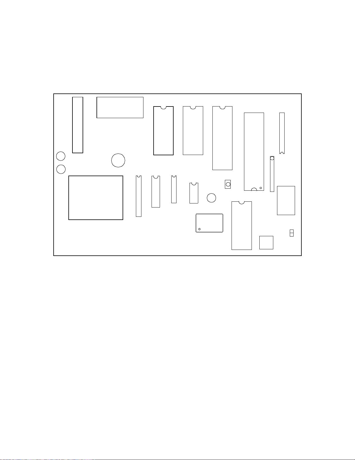
1. Lift off the front display panel on the DCX 250.
Figure 4 shows the inside of the DCX 250 controller.
Notice the board now directly in front of you is the power supply.
Look to the upper left corner for the AC power connection. You
must wire the AC power to the three screws on the upper left side of
the power supply.
2. Thread the AC power cable through the cutout in the top of the
DCX 250 cabinet.
Caution
Be sure to connect all three wires, HOT, NEUTRAL, and GROUND.
Otherwise, the controller could malfunction.
DCX 250 Installation Guide 9
Page 18
3. The three screws are labeled GND NEUT HOT. The three wires at
the end of your AC cable are black, white, and green.
4. Place the green wire under the metal plate behind the left screw,
labeled GND.
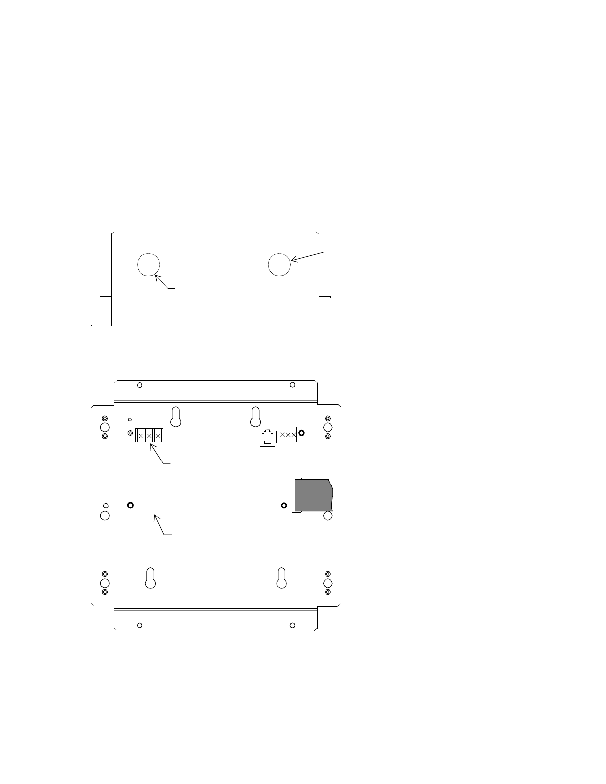
Figure 4. Location of AC Power Connection,
Inside DCX 250 Cabinet
SIDE, TOP VIEW
Hardware Instal lation
AC Power
Cable Enters
Here
FRONT VIEW, CABINET OPEN
GND
NEUT
HOT
AC Power
Connection
Power Supply
Infinet
Cable
Enters Here
10 DCX 250 Installation Guide
Page 19

Hardware Installation
5. Tighten the screw with a flathead screw driver.
Figure 5 shows the position of the plate, where to place the wire, and
how the screw fits on the plate. You can see how the screw holds
the plate in place once you tighten it.
Figure 5. Metal Plate and Screw for Power Supply Wire
6. Place the white wire under the metal plate behind the middle screw,
labeled NEUT.
Metal Plate
Insert Wire Here
7. Tighten the screw with a flathead screw driver.
8. Place the black wire under the metal plate behind the right screw,
labeled HOT.
9. Tighten the screw with a flathead screw driver.
Connecting the Infinet
You wire the Infinet to the controller using the following procedure:
1. Lift off the front display panel on the DCX 250 controller cabinet.
Look at the board now directly in front of you.
Figure 6 shows the Infinet connection, a block terminal connector in
the upper right corner. You must wire Infine t to that connector.
2. Thread the Infinet cable through the cutout in the top of the
controller.
DCX 250 Installation Guide 11
Page 20

Figure 6. Location of Infinet Connection,
Inside DCX 250 Cabinet
SIDE, TOP VIEW
Hardware Instal lation
AC Power
Cable Enters
Here
FRONT VIEW, CABINET OPEN
GND
NEUT
HOT
Infinet
Connection
Power Supply
Infinet
Cable
Enters Here
12 DCX 250 Installation Guide
Page 21

Hardware Installation
Figure 7 illustrates how to w ire the Infinet cable to the block term inal
connector.
Figure 7. Infinet Cable Wiring
Infinet Connection
WHITE
+
–
WHITE
BLACK
BLACK
SHLD
3. Trim back the shield over the wires.
4. Slip the first wire from the incoming Infinet cable and the first wire
from the outgoing Infin et cable into the hole beneath the screw
labeled with a plus sign.
5. Tighten the screw down on it until the screw holds the wires in place.
6. Slip the second (usually black) wire from each Infinet cable under
the screw labeled with a minus sign (middle) and tighten the screw
down on them.
7. Slip the shields from the incoming and outgoing Infinet cables under
the screw labeled SHLD and tighten the screw down on them.
Wiring the Infinet to the Infinity CX 9000
You connect the last piece of Infinet cabling to the Infinity CX 9000 as
explained in the Andover Controls Infinity CX 9000 Hardware
Installation Guide.
DCX 250 Installation Guide 13
Page 22

Hardware Instal lation
Powering Up/Adjusting the Controller
Both the DCX 250 inside the Infinity CX 9000 and the DCX 250 in its
own cabinet have a battery you need to connect.
Connecting the Battery
Lift off the front display panel on the DCX 250. Inside, on the back of
1
the display screen, find the AA battery on the upper left of the board.
Figure 8 shows the location of the battery. Remove the plastic tab
below the clip on the battery to activate the ba ttery.
The battery is a 850 mA-hr 3.6 V primary lithium battery that maintains
RAM when AC power goes out.
-- 2
Powering Up
The DCX 250 inside t he Infinity CX 9000 runs off the power supply of
the Infinity CX and begins operating when you connect AC power to the
Infinity CX 9000.
For the DCX 250 in its own cabinet, you must check to be sure the following are correct:
1. Be sure the AC power is wired properly. Check to be sure all three
wires have been connected.
2. Be sure the controller has a true earth ground.
3. Be sure you have used the proper cables and correct lengths.
4. Be sure the battery is connected.
If you have completed all appropriate sections in this manual and instal l ed al l Infin et controllers , you are now ready to power up the
controller.
14 DCX 250 Installation Guide
Page 23
Hardware Installation
To start the controller, turn on the AC power source (or close the power
connection) and the controller starts automatically.
Figur e 8. L ocati on of Ba tte ry, Ind ica tor Li ghts , and R eset B utt on,
Inside, on Back of DCX 250 Display
RD Light
TD Light
3.6 V Lithium
-
Battery
+
Reset
Button
CPU Light
LCD View
Angle ADJ
Test
Pins
Checking That Controller Is Operating
Lift off the front display panel on the DCX 250. Inside, on the back of
the display, are the indicator lights.
The illustration above shows the RD (green) and TD (yellow) lights to
the far left middle and the green CPU light near the center. The small
red square to the upper right of the CPU light is the RESET button.
Once the controller starts, the following occurs (and also occurs if you
press RESET):
1. The CPU light begins flashing and flashes every .2 sec.
2. The TD light immediately starts flashing after you let go of the
button to show data is being transmitted.
DCX 250 Installation Guide 15
Page 24

3. The RD light begins flashing only if data is being received from
other controllers on the network. This may not happen immediately.
4. If the CPU light flashes every . 1 sec, the CPU has failed an internal
test.
For help with troubleshooting, contact the Andover Controls Technical
Services Department.
Reset Button
The RESET button is the red square button to the upper right of the CPU
light on the controller board (s ee Fi gure 8). Y ou pres s it to init iate a
warm start. The same process that occurs when you power up AC power
occurs when you press RESET.
Hardware Instal lation
Adjusting the LCD View Angle
The LCD view angle adjustment knob is about 1 in. to the left of the
lower right corner of the board.
Figure 9 shows the location of the knob. You turn the knob to adjust the
angle of the display.
The contrast changes at different viewing angles. Adjust it to your
needs.
16 DCX 250 Installation Guide
Page 25

Hardware Installation
Figure 9. Location of LCD View Angle Adjustment, Inside, on
Back of DCX 250 Display
RD Light
TD Light
3.6 V Lithium
-
Battery
+
Reset
Button
CPU Light
LCD View
Angle ADJ
Test
Pins
DCX 250 Installation Guide 17
Page 26

Hardware Instal lation
Connecting the Andover Controls Service Tool
The SERVICE PORT is an RJ 11 (phone) connector on the upper right
side of the power supply, left of the Infinet connection (see Figure 10).
You connect the Andover Controls Service Tool to the DCX 250. The
service tool accesses all DCX 250s and other Infinet controllers on the
same network. For information on availability of the Andover Controls
Service Tool, contact your Andover Controls representative.
Figure 10. Location of Service Port, Inside DCX 250 Cabinet
SIDE, TOP VIEW
AC Power
Cable Enters
Here
FRONT VIEW, CABINET OPEN
GND
NEUT
HOT
Service Port
Power Supply
Infinet
Enters Here
Cable
18 DCX 250 Installation Guide
Page 27

Index
A
AC power
wiring 9
B
battery
location of 14
C
cabinet
dimensions 3
cable
for Infinet 3
for lightning protection 4
circuit requirements for power 3
D
dimensions
cabinet 3
for mounting 7, 8
G
ground
correcting 5
inspecting 5
requirements 4
I
indicator lights
understanding 15
Infinet
connecting 11
lightning arrester for 4
Infinet cable numbers 3
M
mounting
dimensions for 7, 8
P
parts
requirements 7
power requirements
circuit 3
power surges
preventing 4
powering up
procedure to prepare for 14
R
repair
packaging required to ship for 7
requirements
parts 7
power 3
RESET button
location of 16
S
service port
purpose of 18
Service Tool
where to connect 18
T
temperatures
for operating 5
L
LCD knob
location of 16
lightning arrester
for Infinet 4
DCX 250 Installation Guide Index-1
W
wiring
AC power 9
correct wire gauge for ground 5
Infinet connection 11
Page 28

Index-2 DCX 250 Installation Guide
Page 29

30-3001-196 DCX 250 Installation Guide Rev F
 Loading...