

Page 1
UN-RELEASED
REVIEW COPY
2/20/98
Technical Manuals Online! - http://www.tech-man.com
Page 2

1998, Andover Controls Corporation
All Rights Reser ve d
No part of this publication may be reproduced, read or stored in a retrieval
system, or tr ansmitted, in an y for m or by any means, electron ic, mechan ical,
photocopying, re cord i ng, or otherwise, without prior written permission of
Andover Controls Corporation.
Produced in th e United States of America.
Infinity is a trademark of Andover Controls Corporation. All other trademarks
are the proper ty of their respective owners.
Continuum I/O R eference, Version: REVIEW February, 1998
Andover Controls part number: 30-3001-499
Th e i nforma tion in this book is furn ish ed for informat ion a l pur poses onl y, is
subject to change without notice, and should not be construed as a commitment
by Andover Controls Corporation. Andover Controls Corporation, assumes no
liability for any errors or inaccuracies that may appear in this document.
Related Do cumen t s
Continuum Power Supply Reference, 30-3001-702
Continuum CPU Reference, 30-3001-701
Continuum Display Module Reference, 30-3001-711
Andover Controls Corporation
300 Brickstone Square
Andover, MA 01810
(978) 470-0555
fax: (978) 470-0946
Andover Controls Corporation
Technical Manuals Online! - http://www.tech-man.com
Page 3

Radio Interference
This equipment has been tested and found to comply with the limits for a Class A digital device,
pursuant to Part 15 of the FCC Rules. These limits are designed to provide reasonable protection
against harmful interference when the equipment is operated in a commercial environment. This
equipment generates, uses, and can radiate radio frequency energy and, if not installed and used in
accordance with the instructions in this manual, may cause harmful interference to radio
communications. Operation of this equipment in a residential area is likely to cause harmful
interference in which case the user will be required to correct the interference at his own expense.
Note
This digital apparatus does not exceed the Class A limits for radio noise emissions from digital
apparatus set out in the Radio Interference Regulations of the Canadian Department of
Communications.
Avis
Le pr ésent app areil nu mériqu e n ’é met pas de bruit s radioél e ctriq ue s dé passan t les limi tes
applicables aux appareils numériques de la class A prescrites dans le Règlement sur le brouillage
radioélectrique édicté par le ministère des Communications du Canada.
Technical Manuals Online! - http://www.tech-man.com
Continuum I/O System Reference
Page 4

Andover Controls Corporation
Technical Manuals Online! - http://www.tech-man.com
Page 5

Contents
Introduction......................................................................1
Mechanical Installation....................................................4
Overall Dimensions....................................................................7
Door-Mounted Modules..............................................................8
Power-CPU Connections...............................................10
Conne c tion of I/O Mo du le s.......................................................11
Maxim um N um be r of I/O Module s............................................12
Maximum Length of I/O Bus.....................................................12
Connecting Remote I/O Modules with RS-485.........................12
Termina t i on Guidel ine s............................................................13
Individual Module Characteristics................................17
General Wiring Concerns.........................................................17
INPUT Modules
UI-8-10 / UI-8-10-10V.................................................................19
DI-6-AC / DI-6-AC-HV................................................................35
DI-8............................................................................................43
MI-6............................................................................................53
OUTPUT Modules
DM-20........................................................................................61
AO-4-8 / AO-4-8-O.....................................................................73
DO-4-R / DO-4-R-O....................................................................83
DO-6-TR.................................................................................... 91
LO-2 / LO-2-O............................................................................99
MIXED Modules
AC-1 .........................................................................................113
Technical Manuals Online! - http://www.tech-man.com
Continuum I/O System Reference
Page 6

Andover Controls Corporation
Technical Manuals Online! - http://www.tech-man.com
Page 7

TCX 865
ÈNTINUUM
I/O Systems
This manual describes the installat ion, care and use of all Continuum I/O modules.
The
Continuum
various combinat ions of DIN rail-mounted moduleshigh density I/O, CPU and power
supply, and your c hoic e of several user interf ac e modulesin a
to meet your building’s control and monitoring needs. With the
your network gr ows , sim ply add or replace I /O m odules as needed.
Ethernet-based intelligent building system allows you to mix and match
single
Continuum
controller location
system, as
Continuum
The
convection cooling, and a 3-position fr ont cover for easy, hands-free ac c es s. B uilt-in
quick-release fasteners at the back of each I/O module are provided for DIN rail
mountingno tools r equir ed. These fasteners als o s nap into a locked position for panel
mounting. I nput and output connectors ar e located at the bottom of each I/O module and
are removable for eas y field acc es s and m aintenance. All
designed for mounting in an optional NEMA 1-style
The
Continuum
module. Like all
connectors on either side so network expansion is quic k and eas y . Both power
transmiss ion and c om m unic ation signals between the
NetController CP U m odule, and all I/O modules feed thr ough this connection. For added
convenience in cert ain applic ations, such as door c ontrol or lighting control, a s ingle
module or groups of I/ O modules c an be r em otely loc ated and connected using approv ed
cable and powered from a loc al 24 V DC power s upply . Eac h I/ O module features its own
push-button for quick and easy network commis s ioning.
This document covers the standard Input and Output modules. Fo r in format io n
regarding the speci al Continuum enclosure door- mount ed display modules
consult the Andover Con t rol s
I/O modules featur e a sleek, lightweight casing designed f or natural
I/O modules communicate with the
Continuum
modules, the I/ O modules s nap together directly via built-in
Continuum Display Modul e Ref erence
Continuum
Continuum
Continuum
Continuum
enclosure.
NetController CP U
modules are
power supply module,
.
Technical Manuals Online! - http://www.tech-man.com
Continuum I/O System Reference
1
Page 8
I/O System Introduction
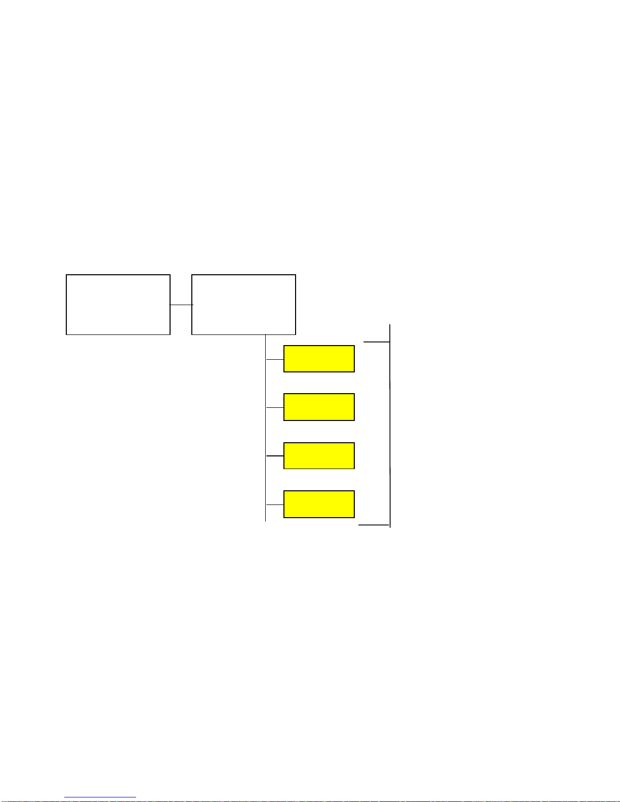
The Continuum I/O system is comprised of a series of modules separated by function
that connect via a common electrical communic ations bus. Each functional com ponent is
enclosed in a plastic c as e c ontaining all of its connections to the outside world. Modules
are connected t o a centr al c ontroller via a standard fiv e c onduc tor connector.
The Continuum sy stem inc ludes at least one power supply and a single cont r oller
module. I/O m odules pr ov ide the controller with the ability to interface with t he outside
world. They c onnec t direc tly and communicate with the CPU. T he following is a typical
architecture drawing of a Cont inuum System:
Power Supply
Controller
I/O Modules
Continuum I/ O modules ar e av ailable in INPUT, OUTPUT, MIXED and DISPLAY
varieties.
2
Andover Controls
Technical Manuals Online! - http://www.tech-man.com
Page 9

The INPUT modules av ailable ar e:
UI-8-10; Univ er s al Input Module
•
UI-8-10-10V; Universal Input Module
•
DI-6 AC; AC Digital Input Module
•
DI-6 AC HV; AC Digital Input Module
•
DI-8; Digit al Input Module
•
DM-20; Digital Input/Output Module (for DIO-20)
•
MI-6; MilliAmp Input Module
•
The OUTPUT modules available ar e:
AO-4-8-O; Analog Output Module (with override)
•
AO-4-8; Analog O utput Module
•
DO-4-R-O; Relay Out put Module (with override)
•
DO-4-R; Relay Out put Module
•
DO-6-TR; Triac Output Module
•
LO-2-O; Light ing Output Module (with over r ide)
•
LO-2; Light ing Output Module
•
The MIXED modules av ailable ar e:
AC-1; Door, Access Control, Wiegand Module
•
AC-1-ABA; Door, Access Control, ABA Module
•
The DISPLAY modules av ailable ar e:
LB-8; 8-Channel LED B ar Dis play / 8 Push Button Module
•
LS-8; 8-Channel, 3 Digit 7-Segment LED Display/ 16 Push Butt on M odule
•
LC-1; 2-Line LCD Display/ 12 Push Button Module
•
VM-1; Voice Record and Playback Module
•
GA-40; Graphic A nnunc iator Panel
•
Technical Manuals Online! - http://www.tech-man.com
Continuum I/O System Reference
3
Page 10
Mechanical Installation
q
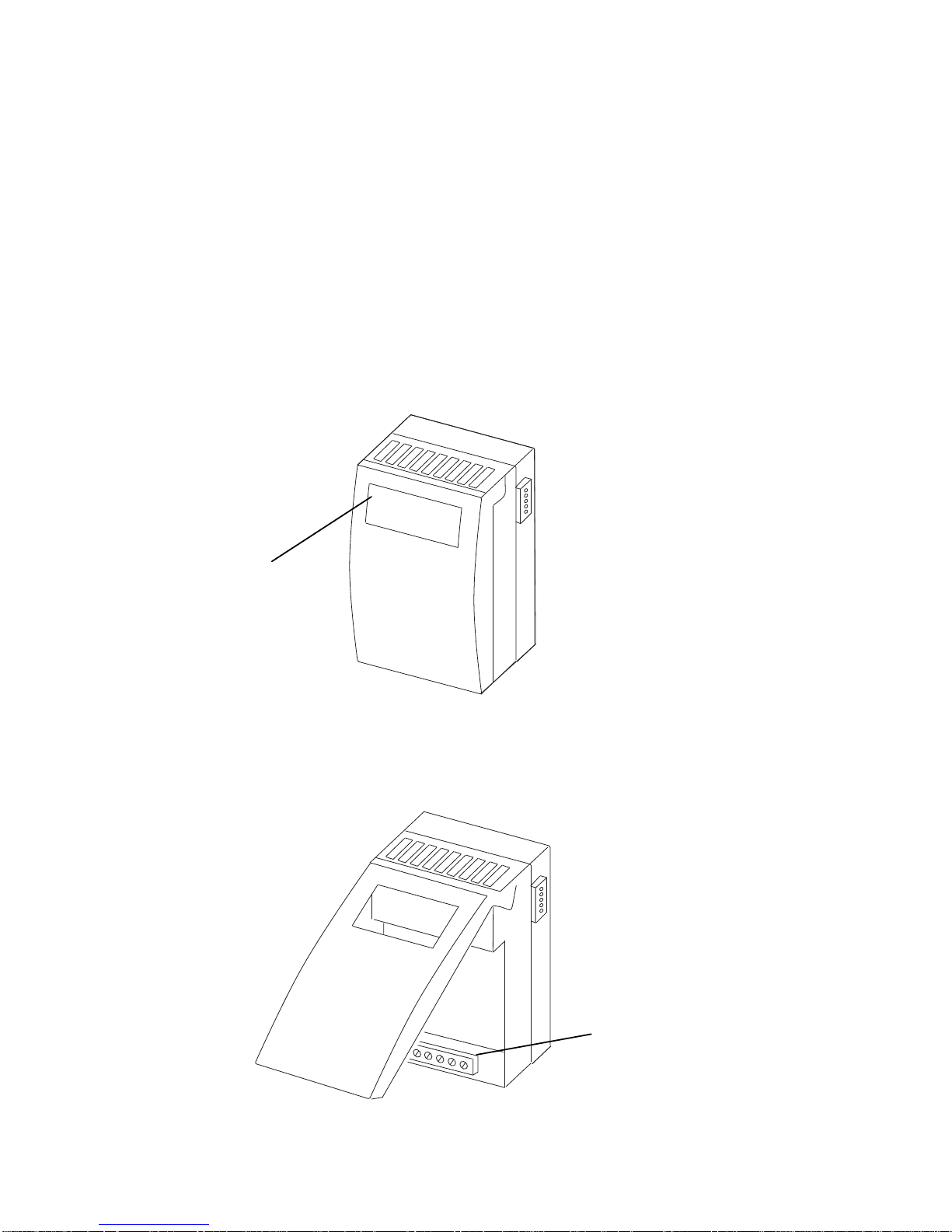
Each I/O module, exc ept the Display variety, is enc los ed in the same standard plastic
case that is designed t o be m ounted on a standard DIN rail or fastened to a panel.
Note: In order to meet agency requirements, it is necessary that t he modules along
with the power supply and controller be housed in another metal enclosure i.e., a
NEMA box or the new Andover Controls Con t in uu m enclosure.
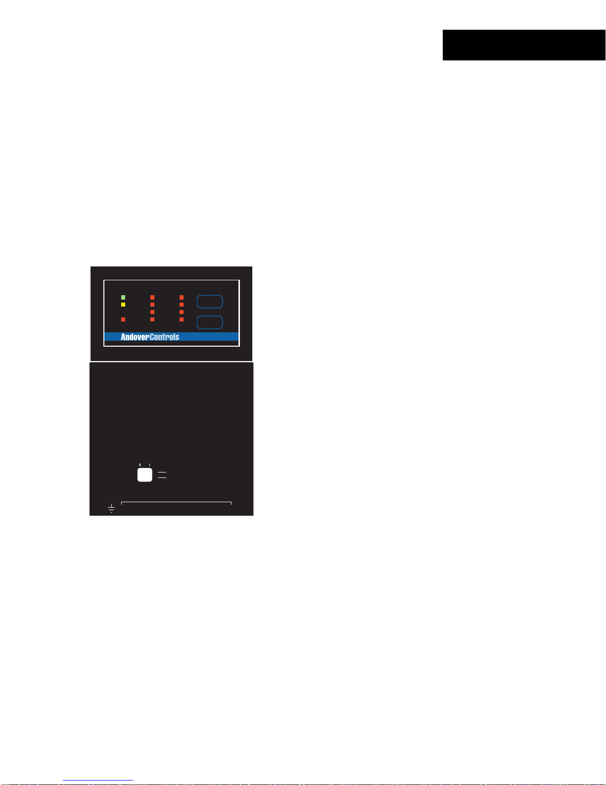
The standard I/ O module plas tic case is illustrat ed below:
Status Indicators
& some switches
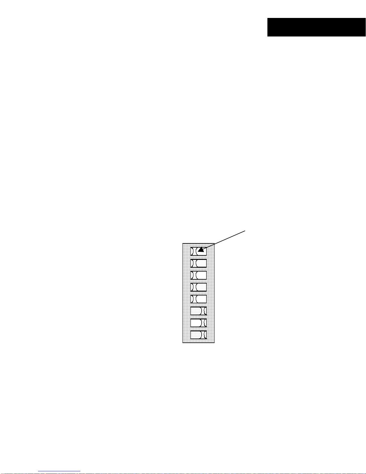
Status indic ators and operator switc hes ar e located on the indicator panel. Ot her
switches available for module configuration may be accessed by lifting the hinged door to
the module as shown.
Connections to
controlled/sensed
uipment
e
4
Andover Controls
Technical Manuals Online! - http://www.tech-man.com
Page 11
Wiring to controlled points or sensors is accomplished via a standard removable screw
terminal block loc ated at the bottom of the module behind t he door . An open area at the
bottom of the c as e allows wires to exit in an appropriate manner.
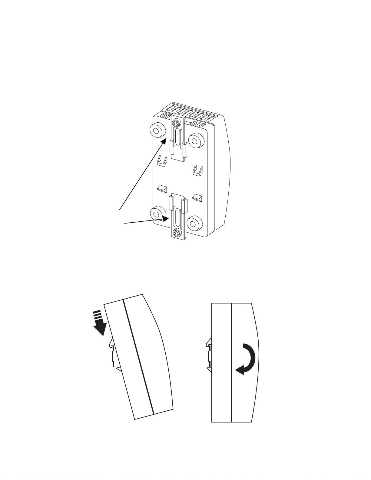
On the back of each module are molded DIN rail guide fingers. The design allows the
module to easily hook onto and slide along a standard DI N rail.
Locking Fingers
With the mounting br ac k ets extended outward, hook the module onto the DIN rail as
shown below:
Technical Manuals Online! - http://www.tech-man.com
Continuum I/O System Reference
5
Page 12
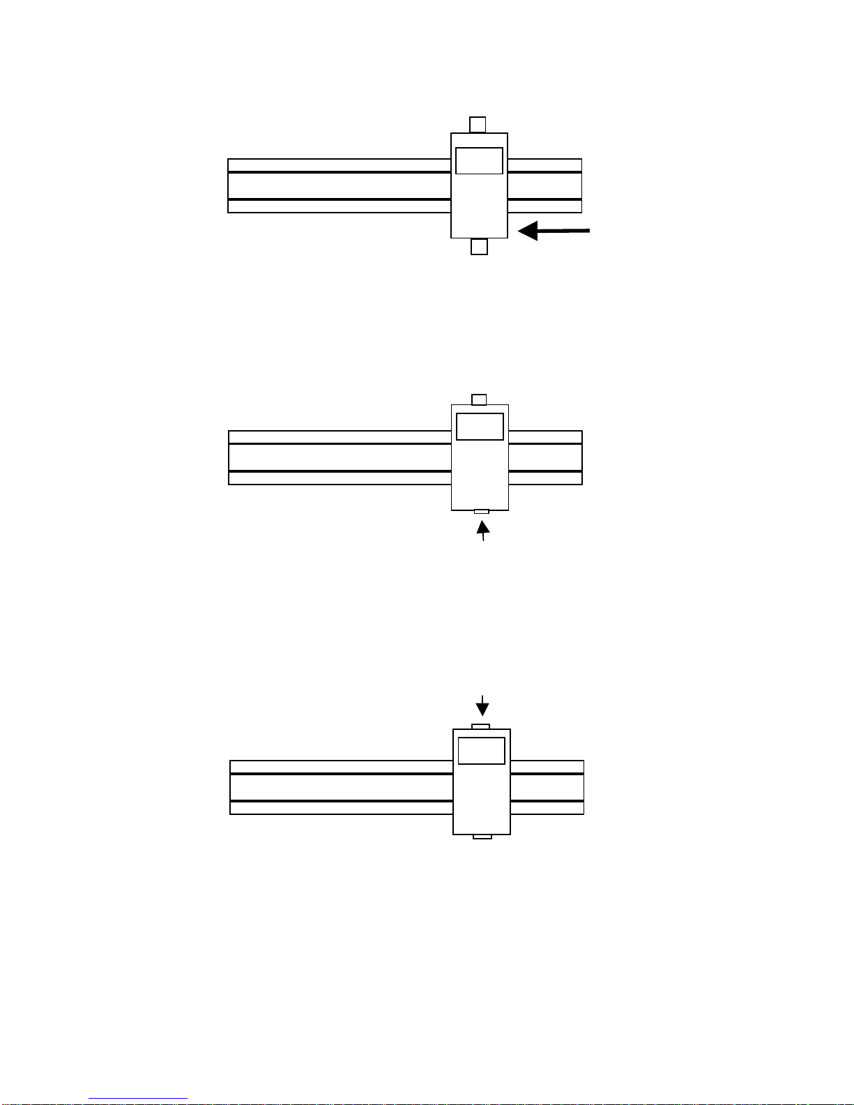
Slide the module into pos ition.
Press the lower mounting bracket inward until it locks the module in place.
Press the upper br ac k et int o its loc k ed pos ition as well.
Once the module is in the des ir ed pos ition, it is locked to the rail by pushing t he bottom
clamps inward. A ft er the bottom is secure, press the top clamp inward to complete the
operation.
6
Andover Controls
Technical Manuals Online! - http://www.tech-man.com
Page 13
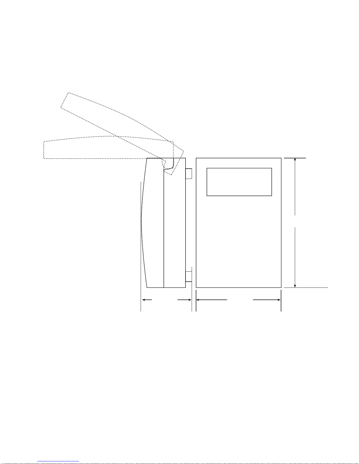
Overall Dimensions
The overall dimensions of the standard I/O case are as shown:
6.70''
(170.2 mm)
2.50 ''
(63.5 mm)
Technical Manuals Online! - http://www.tech-man.com
3.50 ''
(88.5 mm)
Continuum I/O System Reference
7
Page 14
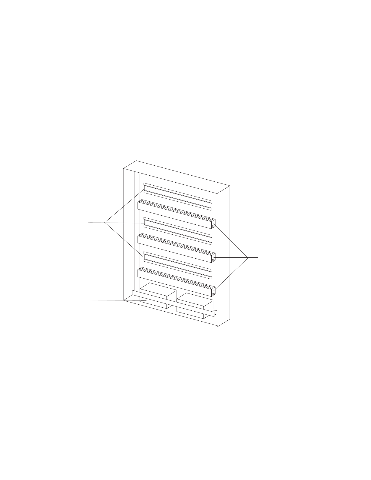
Enclosure-Mounted Modules
The modules that are des igned to be mounted to the new Andover Contr ols Continuum
enclosure fit into openings left by removing panels in the front door.
The new enclosure prov ides a plac e to mount a power supply, CPU and up to ten DIN rail
mounted I/O m odules . Sev er al dis play m odules c an be aff ix ed to the front panel.
The enclosure is a 6” deep NEMA box with integral display panels, DIN rails, cable
troughs and a battery storage compartment.
DIN Rail
Cable Trough
Battery
Storage
The enclosure f eatures three DIN rails and cable management accessories. Use of t he
new enclosure is not r equir ed, however, it provides a c onv enient method of construct ing
small local systems.
8
Andover Controls
Technical Manuals Online! - http://www.tech-man.com
Page 15
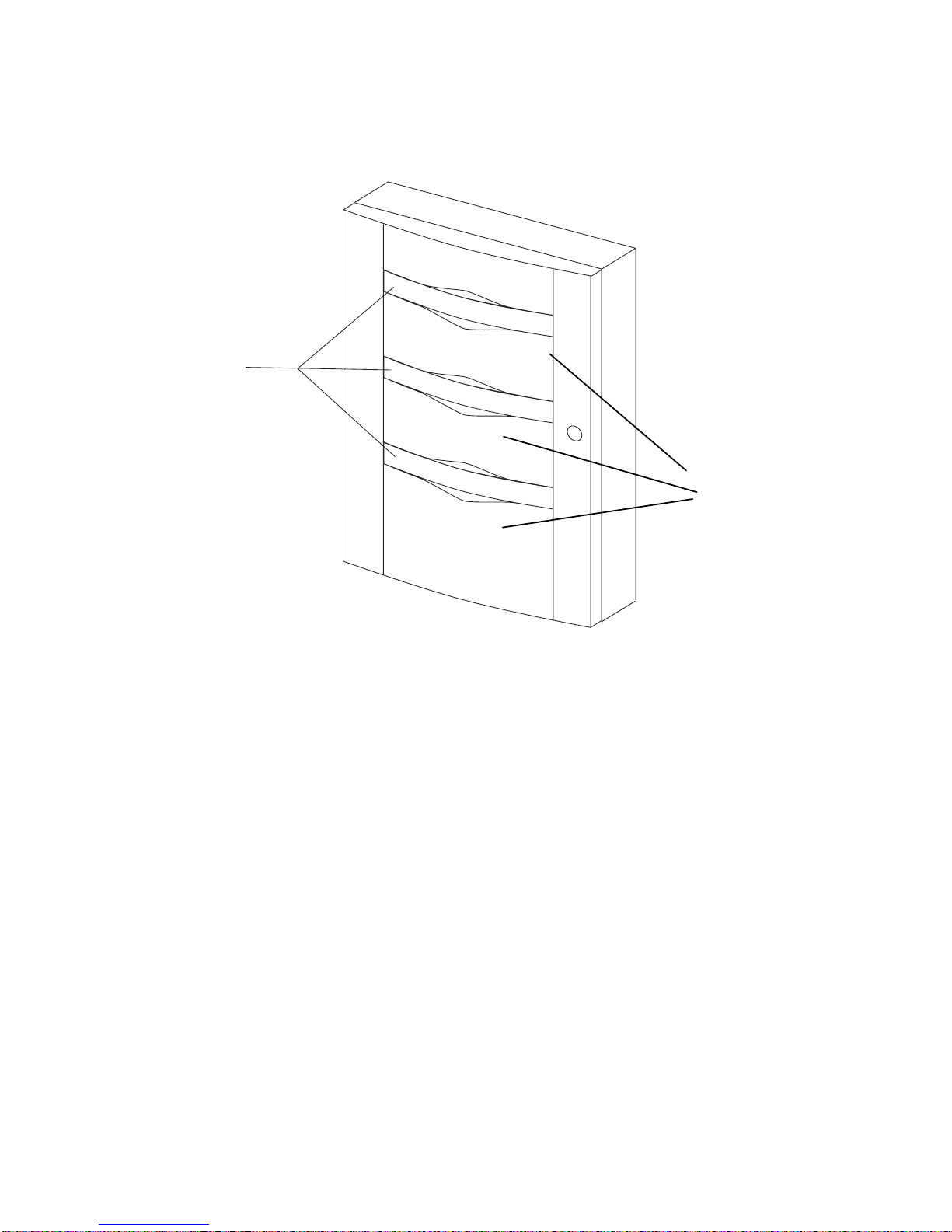
The front door of the enclos ur e c ontains removable sections into which special operator
display and control m odules m ay be m ounted. Alternately, Plex iglas panels m ay be us ed
to view the stat us lights of all internal modules when t he door is closed.
Removable
Display Panels
Spacers for
Additional Displays
Technical Manuals Online! - http://www.tech-man.com
Continuum I/O System Reference
9
Page 16

Power-CPU Connections
The Continuum Net Controller CPU module includes a c onnec tor on the upper right
side of its case f or fur ther distribution of the 24 VDC input power and s pec ial I/O
communications s ignals to all I/O modules. Continuum I/ O modules us e these signals
for power and comm unic ations as well.
The power-I/O c onnec tor is a five pin male assembly that is designed to eas ily ins er t
directly int o the left side (input) connect or of any I/ O module. The signals within that
connector are as follows:
PIN Function
5 +24 VDC
4 24 VDC Return
3 Ground
2 Comm B
1 Comm A
The system power s upply gener ates a +24 VDC source for all modules in the syst em.
This power sourc e is received through the input power c onnec tor on the left side of
the CPU module and sent through to pins 4 and 5 of this connector. Pin 3 (Ground) is
intended as a signal ground connec tion.
Communications between the CPU and I/O modules is through a two-signal serial
interface that can be internally conf igur ed as either RS 485 or Echelon LON FTT-10.
Pins 1 and 2 (Comm B and Comm A) provide the electrical connection for this
interface.
5
10
Andover Controls
Technical Manuals Online! - http://www.tech-man.com
Page 17
Connecti on of I/O Modul es
y
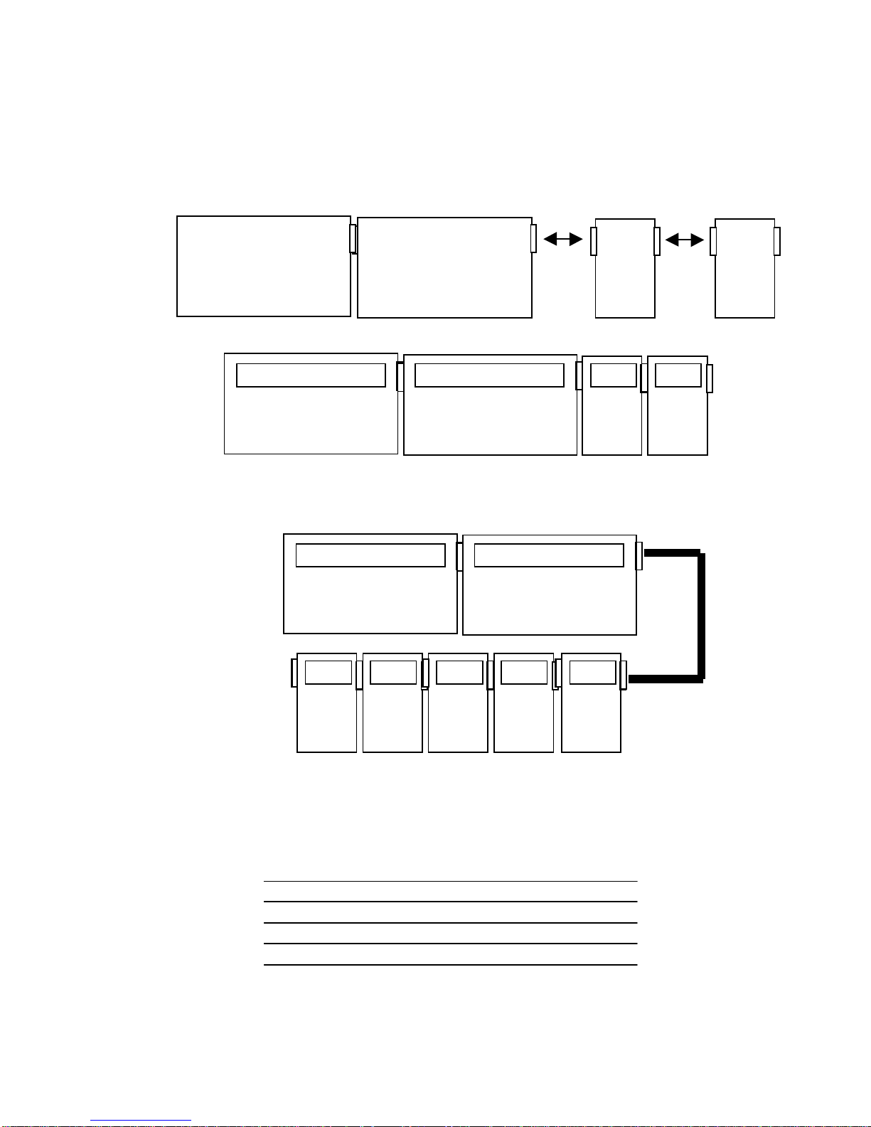
The CPU can directly c onnec t to I/O without the use of cables thr ough a system of
built-in plugs and jacks. All I/O modules include two complementary module interconnectors.
Creating a system is as simple as physically plugging the modules together.
Power Suppl
CPU
I/O
I/O
In vertical extended systems, I/O modules may be located above or below other
modules. In this c as e, cable as s em blies br idge the I/O modules together .
The cable necessar y to connect the CPU and external I/O modules is f iv e c onduc tor
and would be attached using a plug-in screw terminal connector. Connect ion
between the modules is one- to-one straightfor war d wir ing as s hown below:
5
4
3
2
This connect or is available f r om A ndov er Controls under part number 01-2050- 283;
Wieland manufactures it under part number 25.340.0553.0.
Technical Manuals Online! - http://www.tech-man.com
5
4
3
2
Continuum I/O System Reference
11
Page 18

Maximum Number of I/O Modules
There is no operat ional lim it to the number of I/O modules connected to the CPU except
the capacity of t he power s upply . It is pos s ible to insert auxiliary power supplies into the
I/O bus to increase the number of modules support ed.
To determine the maximum number of I/O modules your system can support, subtract the
power requirements for each module from the maximum available f r om y our power
supply.
PS 120/240 AC 50 U, UPS power supply pr ov ides 35 Watts of power
•
PS 120/240 AC 50, non-UPS power s upply pr ov ides 50 Watts of power
•
PS –48 DC 50, Battery operated power supply provides 50 Wat ts of power
•
NetController r equir es 15 Watts of power
•
Start by subt r acting the NetController from the power av ailable from your power supply .
PS 120/240 AC 50 U
35 – 15 = 20 Watts of available power f or I/ O
PS 120/240 AC 50
50 – 15 = 35 Watts of available power f or I/ O
PS –48 DC 50
50 – 15 = 35 Watts of available power f or I/ O
The power requirements for each I/O module is list ed in the
Reference Guide
ACC # 30-3001-499 and can be found on indiv idual data sheets.
Continuum I/O System
Maximum Length of I/O Bus
A repeater is nec es s ar y if the cable lengths get too long. The following are
recommendations r egar ding c able lengths for both RS - 485 and FTT- 10 interfaces:
RS-485 Repeater required if length is >2000 ft. (610 m) or after 32 m odules .
FTT-10 Repeater required if length is >8858 ft. (2700 m) bus topology
>1640 ft. (500 m) free topology
Connecting Remote I/ O Modules with RS-485
The Continuum sy stem allows I/ O modules to be placed in a remote location from the
CPU (NetContr oller ) . However, long cable lengths can c aus e s ignal c om m unic ations
problems on the Power /I - O bus.
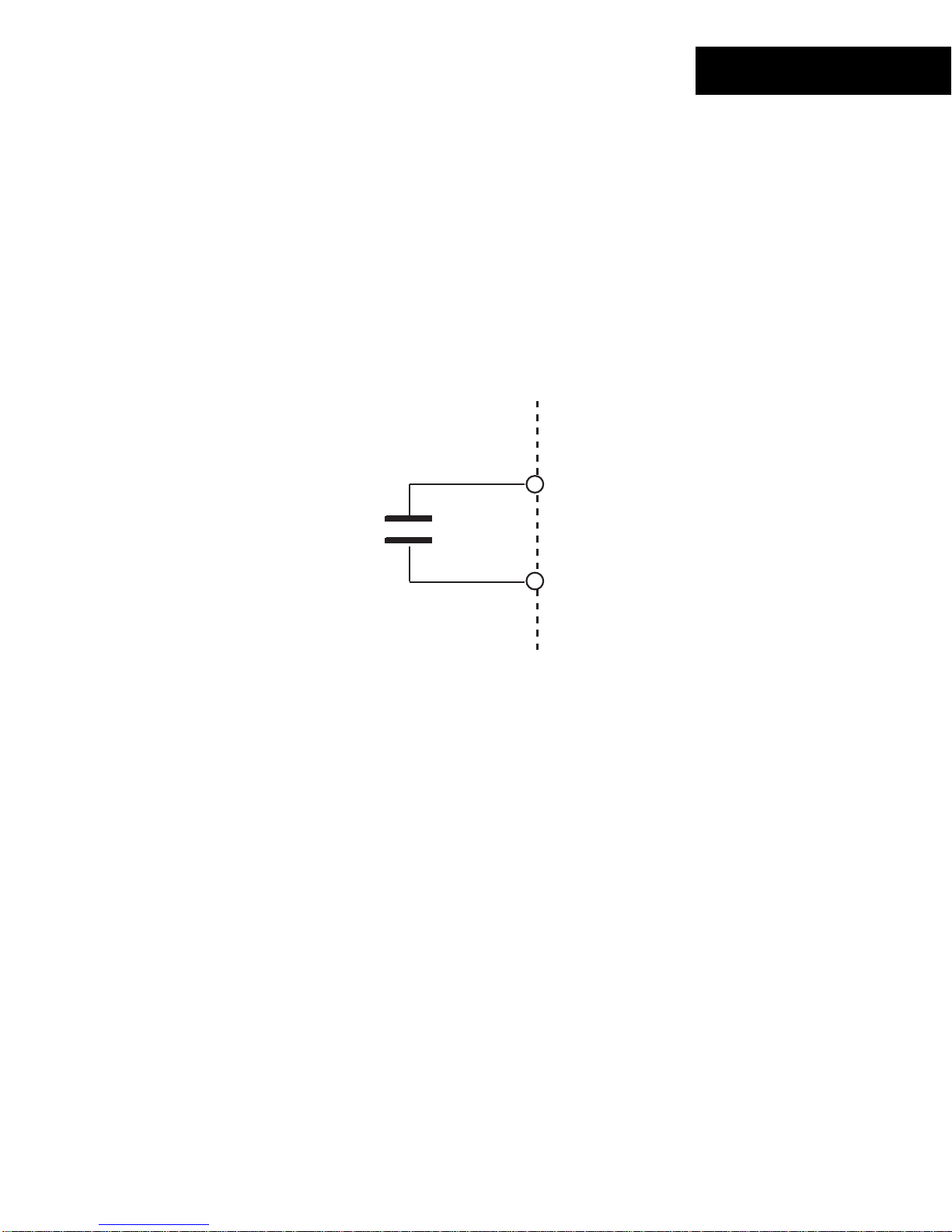
When locating an I /O module remotely it is necessary to add a 120
terminator to the
Ω
bus to compensate for the distance. The terminat or m ust be c onnec ted at both ends of
the bus for proper operation.
12
Andover Controls
Technical Manuals Online! - http://www.tech-man.com
Page 19
Termina t i on Guidel ine s
The following are t y pic al ins tallations that indic ate the placement of the terminat or :
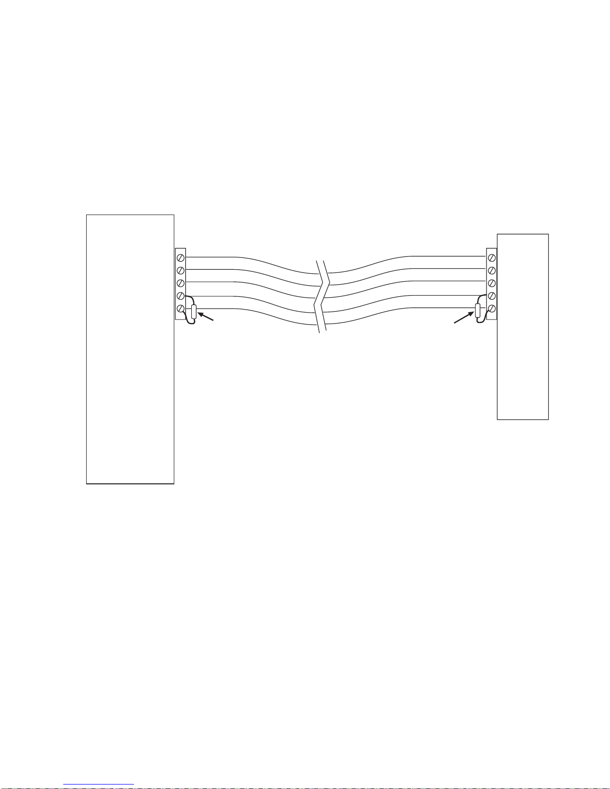
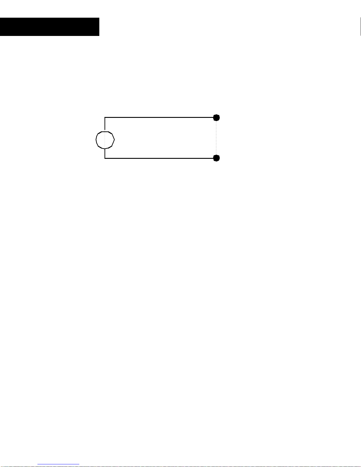
Simple CPU and 1 remot e I/O Module:
The I/O Bus that needs to be terminated is the one formed by the cable at taching the
remote module t o the CPU. I n this c as e, a t erminat or r es is tor is connected across the
communications lines ( pins 1 & 2) directly at the NetController and again at the remote
I/O module.
CPU
5
4
3
2
1
120 Ω
Resistor
120 Ω
Resistor
5
4
3
2
1
Remote
I/O
Module
Technical Manuals Online! - http://www.tech-man.com
Continuum I/O System Reference
13
Page 20
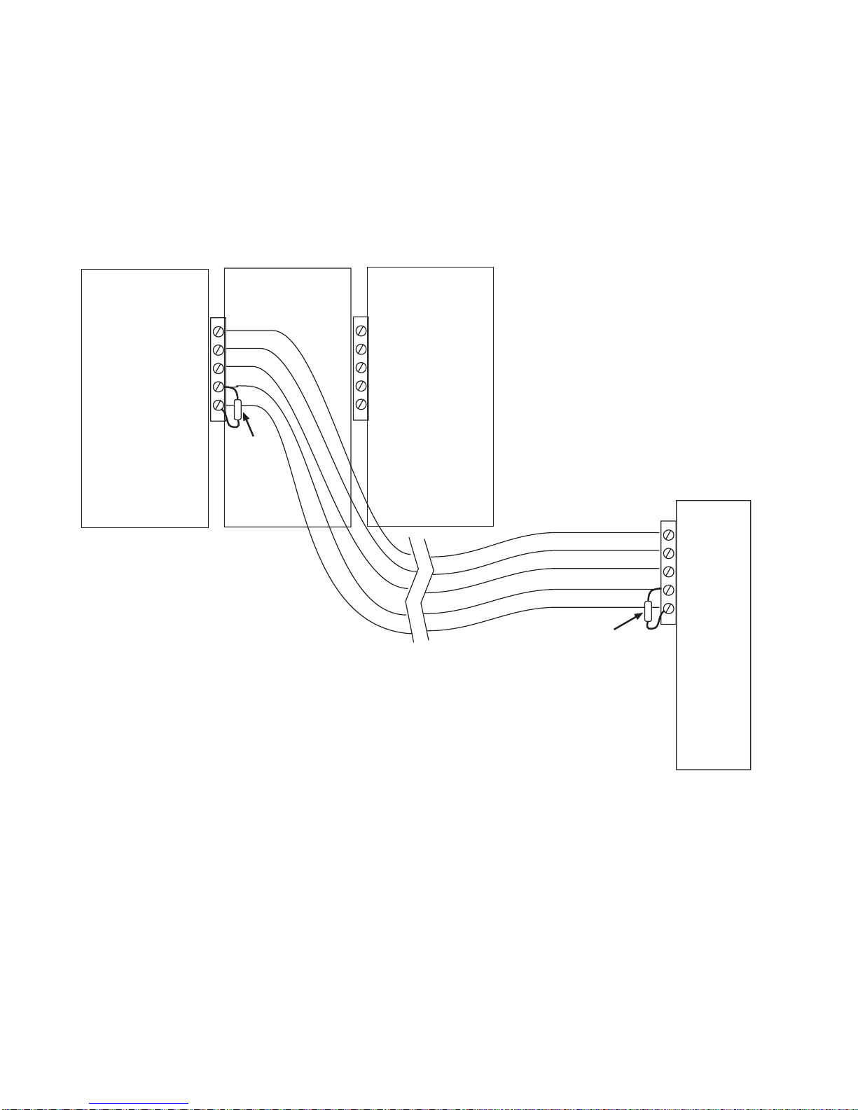
CPU with local and 1 remote I/O Module:
The I/O Bus that needs to be terminated is the one formed by the cable t hat starts at
the NetContr oller and ends at the remote module. The bus that ext ends from the
NetController through the local I/O stac k does not need termination. In this cas e, t he
terminator r es is tor is connected direct ly acros s the c om m unic ations lines ( pins 1 & 2) at
the NetContr oller and again at the remote I/O module.
CPU
120 Ω
Resistor
Local
I/O
5
4
3
2
1
5
4
3
2
1
Local
I/O
120 Ω
Resistor
5
4
3
2
1
Remote
I/O
Module
14
Andover Controls
Technical Manuals Online! - http://www.tech-man.com
Page 21
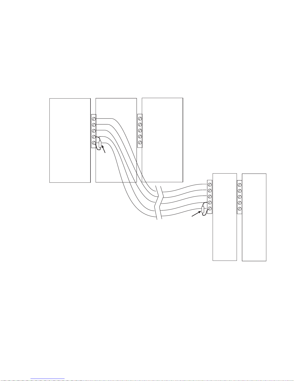
CPU with local and sever al r em ote I/O Modules:
The I/O Bus that needs to be terminated is the one formed by the cable t hat starts at
the NetContr oller and ends at the first remote module. The bus that extends from the
NetController through the local I/O stac k and the one that starts at the first remote
module and extends t hr ough s ubs equent modules do not need terminat ion. In this
case, the term inator resistor is connected dir ec tly across the communicat ions lines
(pins 1 & 2) at the NetContr oller and again at the first remote I/O module.
CPU
120 Ω
Resistor
Local
I/O
5
4
3
2
1
5
4
3
2
1
Local
I/O
120 Ω
Resistor
5
4
3
2
1
Remote
I/O
Module
5
4
3
2
1
Remote
I/O
Module
Technical Manuals Online! - http://www.tech-man.com
Continuum I/O System Reference
15
Page 22
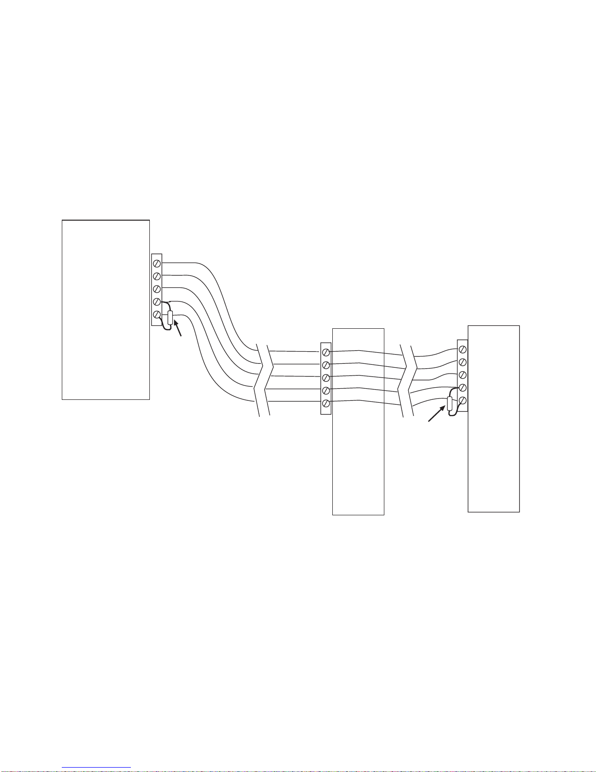
CPU with two remote m odules s epar ated by distance:
The I/O Bus that needs to be terminated is the one formed by bot h cables on eit her
end of the first remot e I/O m odule. In this case, the bus begins at the Net Controller,
flows by the firs t rem ote module and ends at the second. The term inator resistor is
connected directly across the communicat ions lines ( pins 1 & 2) at the Net Controller
and again at the last r emote I/ O module. If the last module is actually a stac k of
directly connec ted I/O modules, the term inator is placed at the first module of the
stack as indicated in the scenario described on the previous page.
CPU
5
4
3
2
1
120 Ω
Resistor
5
4
3
2
1
Remote
I/O
Module
120 Ω
Resistor
5
4
3
2
1
Remote
I/O
Module
16
Andover Controls
Technical Manuals Online! - http://www.tech-man.com
Page 23

Individual Module Characteristics
This section of the document describes the various I/O modules and presents interfacing
information. Each module is presented in it s own mini-sec tion. The part number
designator for the module being described is printed on the outer edge of each page.
General Wiring Concerns for All Modules
Do not remotely gr ound any part of t he input sensor wiring. Remote gr ounds c onnec ted
to the return t er m inal c ould m ak e the syst em oper ate incorrectly or damage the
equipment. T he s ignal r eturn is not true earth ground. It is an elect r onic r eferenc e point
necessary t o interpret the sensor properly.
It is recommended that you run input wiring in a conduit s epar ate from AC power or
output wiring and avoid long wir ing r uns .
For reliable input oper ation, follow thes e input wiring guidelines:
Never lay wires acr os s the surfac e of a printed circuit board.
•
Wires should never be within 1 in. or 25 mm of any component on a printed
•
circuit board.
Use shielded input wire.
•
Terminate the shield of the input wires at one end of the r un only—preferably at
•
the end where your I/O module is loc ated.
Be careful when stripping wire not to drop small piec es of wire ins ide the cabinet.
•
Don’t run your input wir ing in the same conduit with AC power.
•
Don’t run your input wir ing in the same conduit with your output wir ing.
•
Grounding the Modules
Each module includes a screw terminal connection for Earth ground. It is important that
this connect ion be m ade as c los e to the module as pos s ible.
Caution
Do not externally ground any input signal connected to the modul e. This may
damage the unit. Sign al return terminals are not connected to Eart h G round.
Technical Manuals Online! - http://www.tech-man.com
Continuum I/O System Reference
17
Page 24

18
Andover Controls
Technical Manuals Online! - http://www.tech-man.com
Page 25
UI-8-10
The UI-8-10,
Continuum
’s universal input m odule, provides 8 universal inputs, software
configurable as voltage, thermis tor, digital, or counter point types. Each point can also be
configured as a super v is ed input for security monitor ing, providing separate indic ation of
alarm and trouble conditions. This module is a perfect choice for any mix of temperat ur e,
pressure, flow, status points, and similar inputs in a cont rol system, with a 0-5 volt input
range and 10 bit A/D c onv er s ion.
The UI-8-10- 10V m odel is available f or 0- 10V applic ations. It provides the identical point
type select ion; but is equipped with individual voltage div ider DIP switches on each input,
allowing each to be configur ed for a 0-10 volt range.
FEATURES
POWER
COMM
STATUS
USE COPPER CONDUCTORS ONLY
USE COPPER CONDUCTORS ONLY
INPUT TYPE REFERENCE RANGE
TEMPERATURE ON 5 V
5V RANGE OFF 5 V
10V RANGE OFF 10 V
READER
POWER
+
V
IN1
123456789101112
12
SWITCH SETTINGS
REFERENCE
RESISTOR
OFF ON
+ 5V, 100mA
+ 12V, 180mA
READER
G
DC
A
N
T
D
A
/
1
3
IN1
IN2
IN3
IN4
SUPERVISED
IN5
INPUTS(0-5V)
IN6
IN7
1
23
L
E
D
IN8
L
A
O
D
K
U
O
ANALOG INPUTS
X
R
/
0
IN3 IN4 RETIN2 RET IN5 IN6 RET IN7 IN8 RET
4
56
7
ON
OFF
AUTO
R
E
X
8
1-DOOR
VOLTAGE
RANGE
5V 10V
CONTACT RATING:
DIGITAL OUTPUTS
1-DOOR
R
E
T
10 11 12
9
COMMISSION
RESET
UI-8
ON
OFF
AUTO
13 14 15
OUT 2
OUT2
•
•
•
•
8 Universal Input s
10 bit Resolution
0-5V or 0-10V Input Range
Supports Voltage, Thermistor, Digital,
Counter and Supervis ed E lec trical
Types
•
Pull-up Resistor Dis able S witches
Technical Manuals Online! - http://www.tech-man.com
Continuum I/O System Reference
19
Page 26

UI-8-10
SPECIFICATIONS
ELECTRICAL
Power Consumption:
0.7 Watt at 24VDC max.; normally provided by
supply module.
Continuum
power
Overload Protection:
INPUTS
Number of Inputs:
Input Types:
Input Protection:
Input Impedance:
Input Connections:
Voltage: UI-8-1 0 (0-5V) UI-8-1 0-10V (0-10V mo d e)
Range: 0-5 volts 0-10 volts
Resolution: 5 mV 10 mV
Accuracy: ±15 mV (± 0.3% FSR) ±40 mV (±0.4% FSR)
Filtering: Corner Frequency at 15 Hz, –20 db/decade
Calibration: Permanent (factory)
Thermistor:
Type: 10 KΩ, Type III Thermistor
Range: -30 to 230°F
0.5A resettable fuse with transient voltage suppressor (TVS) and
reverse polarity protection.
8 Universal inputs; 10 bit resolution
Voltage, Thermistor, Digital, Counter, and Supervised
24V AC/DC allowed to any single input
(40V transient voltage suppressor on each input – UI-8-10-10V)
5 MΩ w/pull-up disabled; 10 KΩ w/pull-up enabled – UI-8-10
(4.4 KΩ w/pull-up enabled in 0-10V mode UI-8-10-10V)
Two-piece, 13-position removable terminal block
(-34 to 110°C)
Resolution: 40 to 100°F range 0.20°F typical
(4 to 38°C) (0.11°C typical)
Accuracy: 40 to 100°F range ± 1.0°F (includes 0.36° error for thermistor)
(4 to 38°C) (±0.55°C)
Digital & Counter:
Input Type: Contact Closure
Frequency: 4 Hz max.
Pulse Width: 125 ms min.
Supervised:
Input Type: Single or Double Resistor Supervision, Parallel or Series Circuit
20
Andover Controls
Technical Manuals Online! - http://www.tech-man.com
Page 27
UI-8-10
I/O Connections
The actual input connect ions are located on a twelve-position removable screw terminal
connector located at the bottom of the module. Input wir es s hould enter from either the
top or bott om wiring t r oughs , and should c om e from the left side of the rack (by
convention).
The inputs are labeled IN1, IN2, IN3, and so fort h. Eac h pair of inputs is followed by a
connection labeled RET for the input signal retur n, resulting in a sequence of I N1, I N2,
RET, IN3, IN4, RET, and s o on. F or any given input, you should use the closest r eturn
terminal either before or after that input —the nex t return terminal goes with t he next two
inputs, and so on.
The twelve-pos ition connector allows for eight inputs and four signal ret ur ns .
The diagram below indicat es wher e eac h input number is located in the terminal block.
Shield/Eart h Ground
1.
2.
3.
4.
5.
6.
7.
8.
9.
IN 1
IN 2
RETURN
IN 3
IN 4
RETURN
IN 5
IN 6
RETURN
10. IN 7
11. IN 8
12. RETURN
READER
POWER
Technical Manuals Online! - http://www.tech-man.com
POWER
COMM
STATUS
COMMISSION
RESET
UI-8
USE COPPER CONDUCTORS ONLY
USE COPPER CONDUCTORS ONLY
ON
OFF
AUTO
IN1
IN2
IN3
IN4
SUPERVISED
IN5
INPUTS(0-5V)
IN6
IN7
23
D
IN8
R
O
E
O
X
R
7
8
1-DOOR
VOLTAGE
RANGE
5V 10V
CONTACT RATING:
DIGITAL OUTPUTS
1-DOOR
R
E
T
10 11 12
9
SWITCH SETTINGS
INPUT TYPE REFERENCE RANGE
TEMPERATURE ON 5 V
5V RANGE OFF 5 V
10V RANGE OFF 10 V
REFERENCE
RESISTOR
OFF ON
+ 5V, 100mA
+ 12V, 180mA
READER
+
G
DC
A
N
V
T
D
A
/
1
IN1
Continuum I/O System Reference
123456789101112
12
3
1
L
E
L
A
D
K
U
ANALOG INPUTS
X
/
0
IN3 IN4 RETIN2 RET IN5 IN6 RET IN7 IN8 RET
4
56
OUT 2
ON
OFF
AUTO
OUT2
13 14 15
21
Page 28
UI-8-10
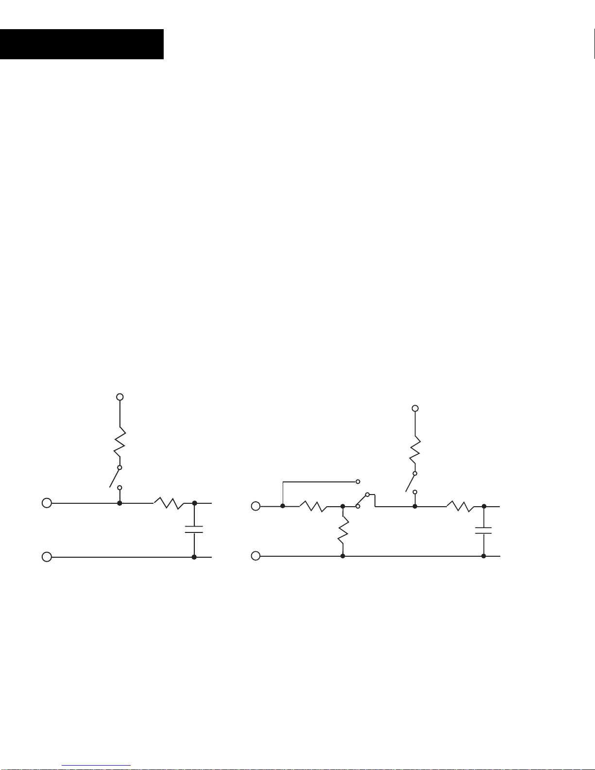
Input Circuitry
UI-8-10 Inputs are essentially volt m eters. Universal inputs can be conf igur ed through
software to become one of five different input c ir c uits:
Temperature
♦
Voltage
♦
Digital
♦
Counter
♦
During configurat ion, the value of the Electrical Type attribute y ou s elec t t ells the
controller how t o interpret the reading fr om each input . Each Universal input is read ev er y
100 milliseconds. This reading is independent of the controller sc an time.
The following is a sim plified schematic of bot h the UI - 8- 10 and the UI - 8- 10- 10V Univ er s al
inputs:
Vref
Vref
IN x
RET
Rref
Swdis
UI-8-10
IN x
RET
2.21K
0-5V
Range
0-10V
2.21K
UI-8-10-10V
Rref
Swdis
The main diff er enc e between the two is the UI-8-10-10V circ uit includes a switch
selectable fr ont-end voltage divider that effectiv ely divides the 10V input signal by two.
22
Andover Controls
Technical Manuals Online! - http://www.tech-man.com
Page 29
UI-8-10
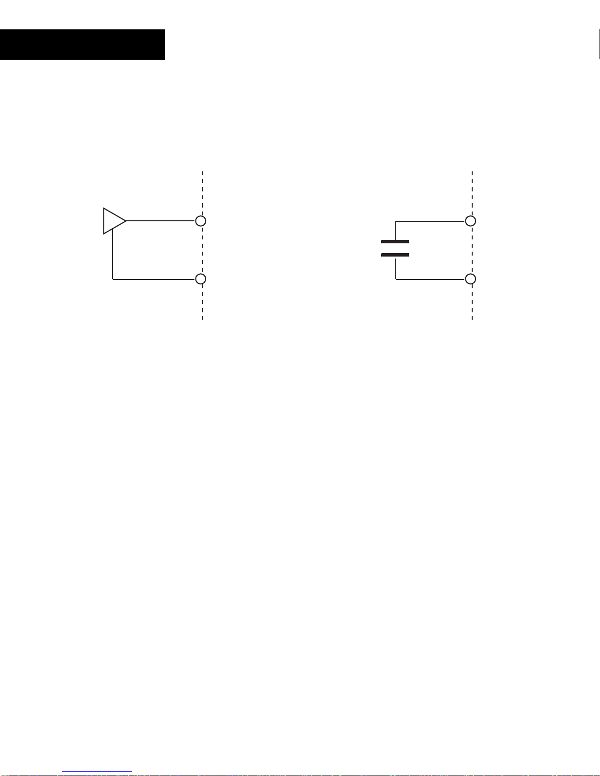
Each input includes a low- pas s filter after the pull-up f or m ed by a series r es is tor and a
parallel capacitor. The resist or is utiliz ed for over-voltage prot ec tion in limiting current t o
two protection diodes (not shown). Not e als o that all input returns are combined and must
be directly connec ted to earth ground. It is possible to have more than one input share a
single return wire. Keep in mind that the current through eac h input is approximately
0.3mA, so volt age dr ops oc c ur with long r uns of sm all gauge wir e.
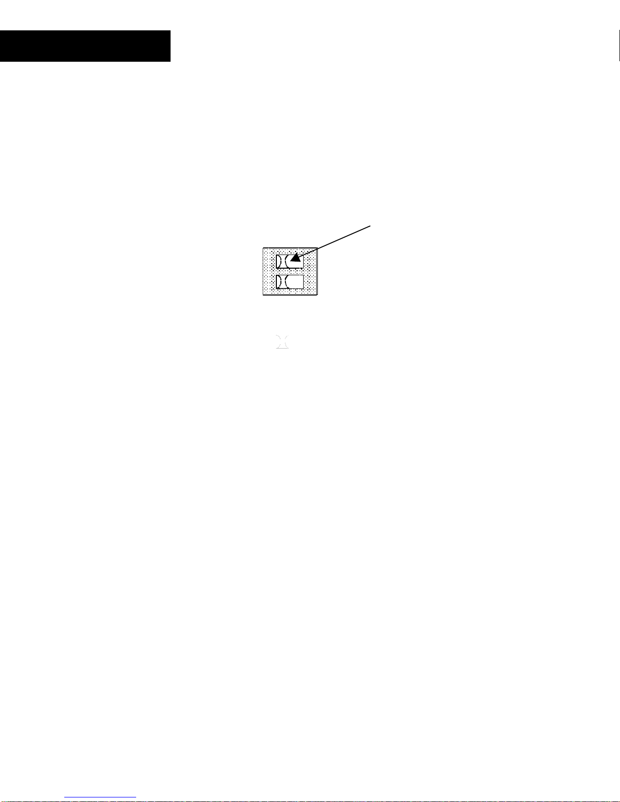
Pull-up Ref erence Resistor Selection Switches
In some measuring inst anc es it is desirable that ther e be no pull-up resis tor. Instead of
physically remov ing or c utting the resistor off the pr inted circuit board, the input m odule
includes a pull-up resistor selection switch (labeled Swdis in the diagr am ) for each input
position. T his s witch allows you to select whether or not y ou want a pull-up r es is tor in the
circuit. A small 8- pos ition switch module is access ible from the front of the module when
the door is opened.
Slide marker
moves left and right
12345678
O N
These switc h modules are c om m only c alled “ DIP Switches” and require a small object
such as the tip of a pen or a small screwdriver to operate them. Each switch position acts
as a “slide switc h” . Pr es s ing the rais ed s lide m ar k er to t he side mark ed “ on” closes or
enables the switc h. To open or disable the switch posit ion, press the slide marker over to
the “off ” side.
Technical Manuals Online! - http://www.tech-man.com
Continuum I/O System Reference
23
Page 30

UI-8-10
Input Voltage Range Selection Switches (UI-8-10-10V Only)
The UI-8-10- 10V m odule allows y ou to choose from two input voltage ranges. Selection
is accomplished by us ing a s witch arrangement that is sim ilar to the operation of the pullup resistor s witches. The Voltage Range switc hes allow y ou to select a range (0-5 V) or
(0-10 V) for each input .
The 0-5V range allows c onnec tions to signals that do not exc eed 5.00V. The 0-10V range
allows connection t o s ignals up to 10.00V. In this mode the circ uit actually uses the same
input measuring cir c uit as the 0-5V range, however , it div ides the voltage present by two
thereby limit ing the internal circuitry to 0-5V. When you read a 0-10V input the actual
reading will be 0-5V. You m us t adjust your readings for the higher r ange v ia formula.
Switching to 10V inputs dramatically low ers the imp edance of the input to
4.4 KΩ.
This small 8-pos ition switch module is located to the right of the pull-up selector s witch
and is accessible f r om the f r ont of the m odule when the door is opened.
24
Andover Controls
Technical Manuals Online! - http://www.tech-man.com
Page 31

Measuring Tem per at ur e
UI-8-10 inputs m ay be conf igur ed to sense temperature by conf igur ing one of the
module’s inputs appropr iately. This is done by s ett ing the Electrical Type to eit her
or
Temp (DEG F)
ACC Temp (DEG C)
input terminal. The following is a schemat ic r epr es entation of the connection:
Thermistor
. Connect a resistive t her m istor s ens or to that
IN x
RET
UI-8-10
ACC
One lead connects to a numbered input terminal, the other to a return terminal.
To use the input for temper ature sensing, the pull-up reference resist or must be
connected into the circuit, ther efore,
be placed in the ‘on’ position
the reference resistor switch for this input must
. When the input point is configured as a temperature
input, the c ontroller utilizes a look-up t able to convert from a voltage reading to a
temperatur e r eading in degr ees Fahrenheit or Celsius.
Caution
Never apply a voltage to a thermistor—doing so alter s the t her m istor ’s ac c ur ac y and
reliability . In fact, it’s a good idea to replac e any therm is tor that has had any sort of
voltage applied to it .
Maximum Wire Run s for Thermist ors
To keep therm istor er r or s minimal, limit the length of wire runs to t he maximum for the
gauge wire you select.
The following two pages inc lude three tables that indicate the maximum length runs for
wires of various gauges to keep errors within certain t em per ature limits when using
thermist or elem ents.
Technical Manuals Online! - http://www.tech-man.com
Continuum I/O System Reference
25
Page 32

UI-8-10
Wire Gauges and Corresponding Maximum Runs for
Sensing Temperatures Up to 70 °F (21 °C)
Gauge
°F (.28 °C) Error 1/4
1/2
°F (.14 °C) Error 1/10
°F (.06 °C) Error
#14 26,700 ft. 13,300 ft. 5,300 ft.
2.5 mm
2
8150 m 4000 m 1600 m
#16 16,700 ft. 8,300 ft. 3,300 ft.
1.5 mm
2
5120 m 2500 m 1000 m
#18 10,500 ft. 5,200 ft. 2,100 ft.
1.0 mm
2
3200 m 1600 m 640 m
#20 6600 ft. 3,300 ft. 1,300 ft.
0.5 mm
2
2000 m 1000 m 400 m
#22 4,100 ft. 2,000 ft. 800 ft.
0.35 mm
2
1250 m 600 m 250 m
Wire Gauges and Corresponding Maximum Runs for
Sensing Temperatures Up to 100 °F (38 °C)
Gauge
°F (.28 °C) Error 1/4
1/2
°F (.14 °C) Error 1/10
°F (.06 °C) Error
#14 12,600 ft. 6,300 ft. 2,500 ft.
2.5 mm
2
3800 m 1900 m 760 m
#16 7,900 ft. 3,900 ft. 1,500 ft.
1.5 mm
2
2400 m 1200 m 450 m
#18 5,000 ft. 2,500 ft. 1,000 ft.
1.0 mm
2
1500 m 760 m 300 m
#20 3,100 ft. 1,500 ft. 600 ft.
0.5 mm
2
950 m 450 m 180 m
#22 1,900 ft. 900 ft. 300 ft.
0.35 mm
2
580 m 275 m 90 m
26
Andover Controls
Technical Manuals Online! - http://www.tech-man.com
Page 33

Wire Gauges and Corresponding Maximum Runs for
Sensing Temperatures Up to 150 °F (65 °C)
UI-8-10
Gauge
°F (.28 °C) Error 1/4
1/2
°F (.14 °C) Error 1/10
°F (.06 °C) Error
#14 4,100 ft. 2,000 ft. 800 ft.
2.5 mm
2
1250 m 600 m 240 m
#16 2,600 ft. 1,300 ft. 500 ft.
1.5 mm
2
800 m 400 m 150 m
#18 1,600 ft. 800 ft. 300 ft.
1.0 mm
2
500 m 240 m 90 m
#20 1,000 ft. 500 ft. 200 ft.
0.5 mm
2
300 m 150 m 60 m
#22 600 ft. 300 ft. 100 ft.
0.35 mm
2
180 m 90 m 30 m
Technical Manuals Online! - http://www.tech-man.com
Continuum I/O System Reference
27
Page 34
(
)
UI-8-10
Measuring DC Voltages
The UI-8-10 inputs may be configured to sense DC voltage by s ett ing the Electrical Type
to
Voltage
the module’s input s pec ifications. The f ollowing is a s c hem atic representation of the
connection:
One lead connects to the numbered input terminal, the other to a return terminal.
When interf ac ing to a voltage output sensor, s pec ific information on the trans duc er may
and connecting the input terminals to a DC voltage sourc e within the range of
INx
+
V
-
RET
return
be required. The pull- up r es is tor of the input circuit will affect the output of the trans duc er .
It is suggested that you disable (set to OFF) the pull-up reference resist or on volt age
•
inputs.
10V Input Notes
It should be not ed that although the 10V input configuration allows you to measure a
higher voltage, y ou s till read a value of 0-5V. You have to convert the reading in your
program.
28
Andover Controls
Technical Manuals Online! - http://www.tech-man.com
Page 35

UI-8-10
Voltage Di vid ers
There are inst anc es when it is nec es s ar y to interface to a voltage source that is higher
than the input r ange of t he m odule. In these cases a voltage divider is neces s ar y .
DC input Voltage Divider
Two resist or values s et up a ratio of voltage drop. These res istor s m ust be sized
appropriately (v alue and wattage) for the source being monitored. The higher the
resistance v alues , the less loading effect t her e will be on the source.
Vref
Rref
Swdis
R1
Vsource
R2
IN x
RET
The circuit s hown abov e is a simple two-resistor volt age div ider c onnec ted to one of the
UI-8-10 module’s inputs. The input circ uitry of the module can measure a maximum of
either 5 Volts or 10 Volt s (UI - 8- 10- 10V only ) . T her efore, the voltage measured acr os s
Rinput must not exc eed this maximum.
In this cas e, be sur e to switch the pull-up resistor out of t he circuit.
Technical Manuals Online! - http://www.tech-man.com
Continuum I/O System Reference
29
Page 36

UI-8-10
Assuming you know the maximum voltage reading you are trying to measure (
source
V
),
perform t he following steps to determine the r es istanc e v alues nec es s ar y to condition the
input for t he module.
1. First, det er m ine the current that will flow through t he div ider . Pick a value that your
source can supply. Let’s say 20 mA. This value will be repres ented by the variable
total
in the following equ ations.
I
2. Determine the total resistance value r equir ed of the entire divider (R1 + R2) to create
20mA given the sour c e voltage by s olv ing the following:
total
R
I
= V
source
total
Example, if you are meas ur ing a s our c e that can supply 0- 30 V:
total
R
= 30 V
20 mA
total
R
= 30 V
.02 A
total
R
= 1500
Ω
The current is constant through the two resistors. Knowing this and the fact that our
input can’t exc eed 5V ( or 10V) c an determine the value of the resistor labeled
3. Determine the v alue of
R
I
R2 = 5 V
2
by solving the following:
R
2
input
= V
total
(assuming you are solving f or 0-5V input)
.02 A
2
R
= 250
Ω
Through subtr ac tion, you can determine the remaining r es is tor value:
total
= R1 + R
R
R1 = 1500 Ω - 250
2
Ω
R
2
.
30
Andover Controls
R1 = 1250
Ω
Technical Manuals Online! - http://www.tech-man.com
Page 37
UI-8-10
Sensing Digital Inputs or Contact Closures
Digital input points ar e des igned to allow the monitoring of logic level signals or contact
closures acros s an input (contact wired bet ween the input and r eturn).
When monitoring a digital logic level signal, t he pull- up r es is tor must be disabled (set
•
to OFF).
To sense a contact closure, the pull-up resistor m us t be enabled (s et to ON).
•
IN x
Contact
Closure
RET
To sense a digital input or contact closure, c onfigure an input point with an Electrical
Type of
Digital
.
A digital input is c ons ider ed “ ON” whenever the voltage acr os s its input meets or exceeds
the ON Threshold. For a c ontact closure, this is 0 (zero) volt s. S im ilar ly , an OFF condition
meets, or is lower than, the Off Threshold. With a contact closure, this is the value of
Vref.
: When configuring a Digital point, ther e is a ‘Polarity’ attribute. If this att r ibute is
Note
enabled, readings are rev er s ed: ‘On’ will occur when t he input is at Vref because the
contact is open, and ‘O ff ’ oc c ur s when the input is at 0 volts because the contact is
closed.
Technical Manuals Online! - http://www.tech-man.com
Continuum I/O System Reference
31
Page 38

UI-8-10
Counting Pulsing Signals or Contact Closures
Counter inputs ar e des igned to allow the monitoring of digital pulse trains or cont act
closures acros s an input just like digital inputs, but they accumulate a total of those
closures and act lik e a c ounter.
Interf ac ing is s im ilar to a digit al input, however, you set the Elect r ic al Type attribute to
Counter
When using an input as a counter , you must take into account the fr equenc y of t he input
signal being counted. Univ er s al inputs do not allow for v er y high s peed c ontact counting.
This module allows counting up to a maximum of 4 Hz or 4 contact closur es or digit al
pulses per second.
instead.
Counter Dut y Cycle
To achieve the m ax imum counter frequency, the amount of time t he signal is O N as
opposed to being OF F must be at least 125 milliseconds.
32
Andover Controls
Technical Manuals Online! - http://www.tech-man.com
Page 39

Status/Control P a nel
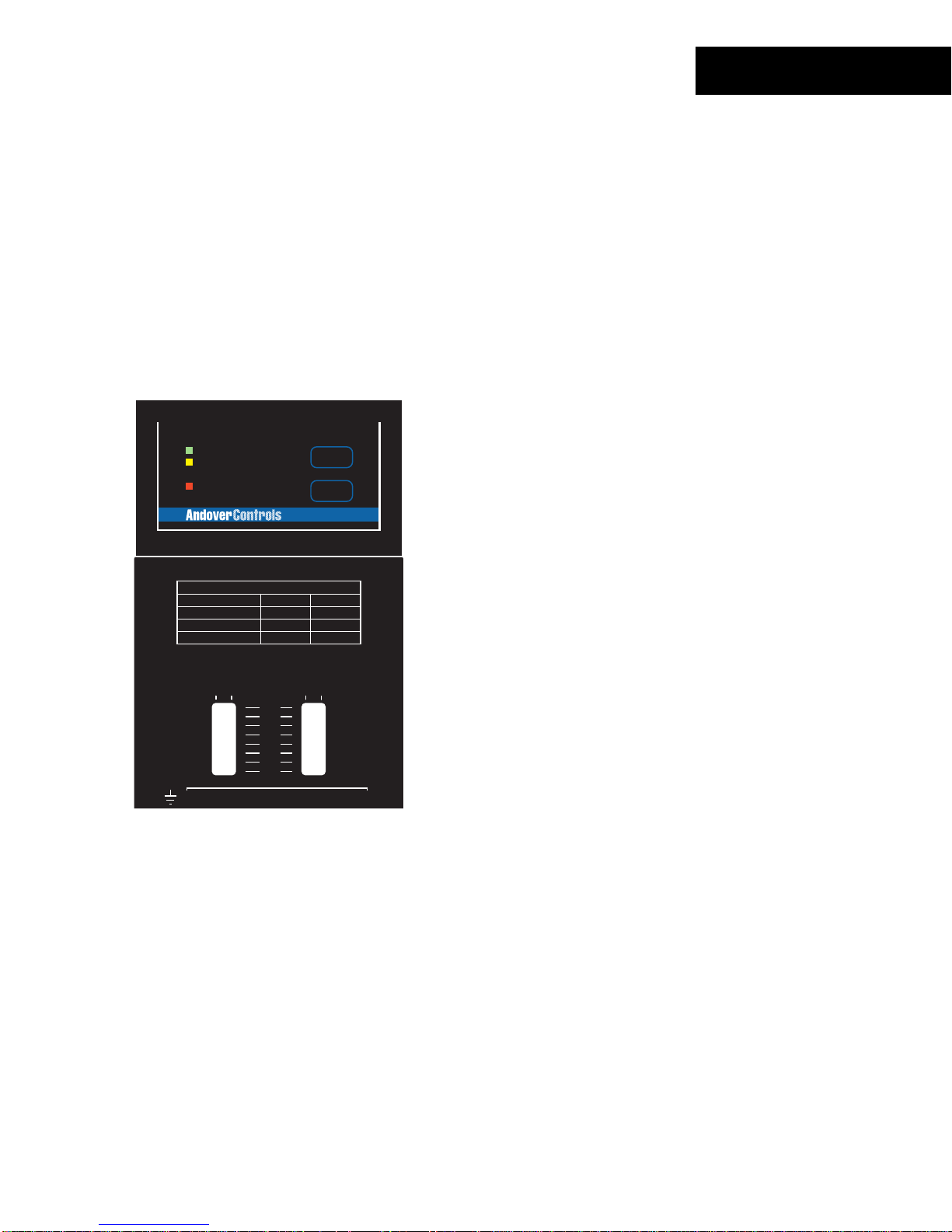
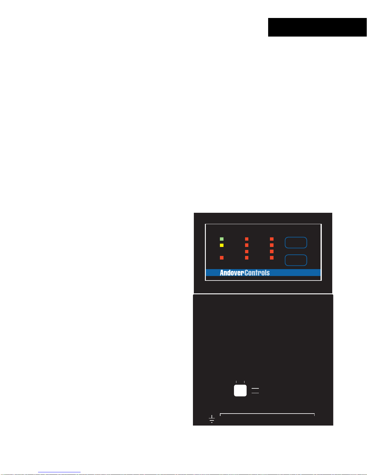
Status In dic a t or s
The UI-8-10 m odule inc ludes a c om plete indicator status panel on the front of the
module.
UI-8-10
POWER
COMM
STATUS
COMMISSION
RESET
UI-8
This panel includes indicators reporting on the status of the following:
POWER
COMM
STATUS
This green indicat or illum inates when DC power is applied through the
Power/IO Bus .
This yellow indicat or illum inates when data is tr ans m itt ed from the
module to the Net Controller. In normal operation, data is only transmit ted
when an input value changes.
This indicator will als o flash periodically as t he NetController check s the
I/O bus periodically .
This red indicat or is nor m ally off . If it is alway s on or flas hing at a fast
rate there is a problem wit h the module.
This indicator c an be m anually illum inated from the Continuum
workstation and used as a troubleshooting aid when locat ing a particular
module. More inf or m ation on using this indicator may be found in t he
Troubleshooting
section of this manual.
This panel also includes two operator swit c hes that perfor m the f ollowing:
COMMISSION
After phy s ic al installation and during configurat ion through the
Continuum workstation, pressing this button registers the module’s
address with t he s yst em. For m or e information, refer to the section on
RESET
Configuring I/ O
Should the module become inoper able, pressing this button resets the
found earlier in this manual.
module. It does not er as e its m emory.
Technical Manuals Online! - http://www.tech-man.com
Continuum I/O System Reference
33
Page 40

34
Andover Controls
Technical Manuals Online! - http://www.tech-man.com
Page 41

DI-6-AC
The DI-6-A C, Cont inuum ’s digital AC input module, has six digital (“wet”) AC inputs for
cost-ef fective ON-OFF status indicat ion of fan motor starters, solenoid valv es , control
relays, or exter nal power s upplies , and similar applications that require a quick and eas y
way to detect voltage. The DI-6-AC monitor s the abs enc e or presenc e of AC voltage
levels directly , with no interposing r elay s needed.
The DI-6-A C can monit or voltages from 24-120V. A DI-6-AC-HV model is als o av ailable
for sensing higher v oltages120-240V. Bot h models can als o ac c ept DC voltages. All
inputs are optic ally c oupled with 2500V isolation on each input for noise-free oper ation.
FEATURES
POWER
COMM
STATUS
INPUT
INPUT
1
2
3
4
5
6
COMMISSION
RESET
6 optically-coupled, digital AC input
•
channels
DI-6
USE COPPER CONDUCTORS ONLY
USE COPPER CONDUCTORS ONLY
WARNING:
HIGH VOLTAGE INSIDE-DANGEROUS TO
UNQUALIFIED PERSONS.
AVERTISSEMENT:
CAUTION:
READER
POWER
MORE THAN ONE DISCONNECT MAY BE
REQUIRED TO DE-ENERGIZE THIS EQUIPMENT.
+ 5V, 100mA
VOLTAGE RANGE(VAC) 50/60 HZ 20 - 132 90 - 280
INPUT CURRENT(mA) 0.4 - 9.0 0.4 - 3.0
+ 12V, 180mA
READER
+
G
DC
A
N
V
L
IN1
IN2 IN3 IN4 IN5 IN6
T
D
K
A
/
/
1
0
123456789101112
4
12
56
3
1-DOOR
ON
OFF
AUTO
HAUTE TENSION A L'INTERIEUR-DANGER
POUR LES PERSONNES NON-QUALIFIER.
DI-6-AC DI-6-AC-HV
CONTACT RATING:
23
D
O
O
R
7
R
E
X
8
24VAC/DC, 5A
DIGITAL OUTPUTS
1-DOOR
R
E
T
10 11 12
9
L
E
D
SUPERVISED
INPUTS(0-5V)
1
A
U
X
DIGITAL INPUTS
ON
OFF
AUTO
OUT 2
OUT2
13 14 15
Will accept A C or DC inputs
•
24-120V AC Input Range
•
120-240V AC Input Range ( DI-6-AC-HV)
Technical Manuals Online! - http://www.tech-man.com
Continuum I/O System Reference
35
Page 42

DI-6-AC
SPECIFICATIONS
ELECTRICAL
Power Consumption:
0.7 Watt at 24VDC max.; normally provided by
supply module.
Continuum
power
Overload Protection:
INPUTS
Number of Inputs:
Input Protection:
Input Connections:
Input Range:
Input Current:
AC Voltage “ON” Threshold:
(Above this voltage is considered “ON”)
AC Voltage “OFF” Threshold:
(Below this voltage is considered “OFF”)
Input Resistance
(±5%): 30KΩ 200KΩ
0.5A resettable fuse with transient voltage suppressor (TVS) and
reverse polarity protection.
6 Digital AC voltage inputs
2500V isolation on each input
Each input has a 270V MOV.
Two-piece, 13-position removable terminal block
DI-6-AC DI-6-AC-HV
20-132 Vrms 90-250 Vrms
5 mA max. 2 mA ma x.
DI-6-AC DI-6-AC-HV
16 Vrms 75 Vrms
8 Vrms 30 Vrms
Ma xim um Turn ON Time:
Maximum Turn OFF Time:
DC Input Voltage Range:
DC Input Current:
DC Voltage “ON” Threshold:
(Above this voltage is considered “ON”)
DC Voltage “OFF” Threshold:
(Below this voltage is considered “OFF”)
36
Andover Controls
20 mS 20 mS
60 mS 60 mS
20-132V 90-250V
5mA max. 2mA max.
20V 90V
12V 45V
Technical Manuals Online! - http://www.tech-man.com
Page 43

DI-6-AC
I/O Connections
The actual input connect ions are located on a twelve-position removable screw terminal
connector located at the bottom of the module. Input wir es s hould enter from either the
top or bott om wiring t r oughs , and should c om e from the left side of the rack (by
convention).
The inputs are labeled IN1, IN2, IN3, and so fort h. Eac h pair of term inals c or r es ponds to
one input. With both AC and DC signals there is no polarity to obs er v e dur ing c onnec tion.
The diagram below indicat es wher e eac h input number is located in the terminal block.
Shield/Eart h Ground
IN 1
1.
IN 1
2.
IN 2
3.
IN 2
4.
IN 3
5.
IN 3
6.
IN 4
7.
IN 4
8.
IN 5
9.
10. IN 5
11. IN 6
12. IN 6
POWER
COMM
STATUS
WARNING:
INPUT
USE COPPER CONDUCTORS ONLY
USE COPPER CONDUCTORS ONLY
HIGH VOLTAGE INSIDE-DANGEROUS TO
UNQUALIFIED PERSONS.
AVERTISSEMENT:
CAUTION:
MORE THAN ONE DISCONNECT MAY BE
REQUIRED TO DE-ENERGIZE THIS EQUIPMENT.
1
2
3
4
INPUT
5
COMMISSION
6
RESET
DI-6
1-DOOR
ON
OFF
AUTO
HAUTE TENSION A L'INTERIEUR-DANGER
POUR LES PERSONNES NON-QUALIFIER.
OUT 2
ON
OFF
AUTO
READER
POWER
Technical Manuals Online! - http://www.tech-man.com
+ 5V, 100mA
VOLTAGE RANGE(VAC) 50/60 HZ 20 - 132 90 - 280
INPUT CURRENT(mA) 0.4 - 9.0 0.4 - 3.0
+ 12V, 180mA
READER
+
G
N
V
IN1
D
123456789101112
12
L
DC
A
E
L
IN2 IN3 IN4 IN5 IN6
T
D
K
A
/
/
1
0
4
56
3
DI-6-AC DI-6-AC-HV
SUPERVISED
INPUTS(0-5V)
DIGITAL INPUTS
1
23
D
A
U
X
R
R
O
E
O
X
R
7
9
8
CONTACT RATING:
24VAC/DC, 5A
DIGITAL OUTPUTS
1-DOOR
E
T
10 11 12
OUT2
13 14 15
Continuum I/O System Reference
37
Page 44

DI-6-AC
Input Circuitry
The following is a sim plified schematic of bot h the DI - 6- A C and the DI-6-A C- HV Digital
Input module:
AC
IN x
15K
OptoCoupler
RET
IN x
RET
275V
MOV
15K
DI-6-AC
100K
275V
MOV
100K
DI-6-AC-HV
10V
40V
AC
OptoCoupler
AC to DC
Converter
AC to DC
Converter
II
II
The main diff er enc e between the two is the DI-6-AC-HV circuit inc ludes a front end that
supports t he higher v oltages.
38
Andover Controls
Technical Manuals Online! - http://www.tech-man.com
Page 45

DI-6-AC
Sensing AC or DC Digital Inputs
Digital input points ar e des igned to provide an ON or OFF reading of a signal ( wir ed
between the input and r eturn). Normally you would ass oc iate an AC or DC voltage input
with a value measurem ent, however, the DI-6 modules include a voltage level trigger t hat
senses the pres enc e of a range of voltages and converts thos e r eadings to ON and OFF
indications.
AC
Signal
IN x
Polarity
Independent
DC
Signal
IN x
To sense an AC or DC digital input , configure an input point wit h an Elect r ic al Type of
Digital
.
The determination of ON or OFF is based upon the following measurement thresholds:
DI-6-AC DI-6-AC- HV
AC Voltage “ON” Threshold:
(Above this voltage is considered “ON”)
AC Voltage “OFF” Threshold:
(Below this voltage is considered “OFF”)
DC Voltage “ON” Threshold:
(Above this voltage is considered “ON”)
16 Vrms 75 Vrms
8 Vrms 30 Vrms
20V 90V
DC Voltage “OFF” Threshold:
(Below this voltage is considered “OFF”)
: When configuring a Digital point, ther e is a ‘Polarity’ attribute. If this att r ibute is
Note
12V 45V
enabled, readings are rev er s ed: ‘ON’ will occur when t he input is at the normal OFF
threshold. OF F occ ur s at t he normal O N thres hold.
Technical Manuals Online! - http://www.tech-man.com
Continuum I/O System Reference
39
Page 46

DI-6-AC
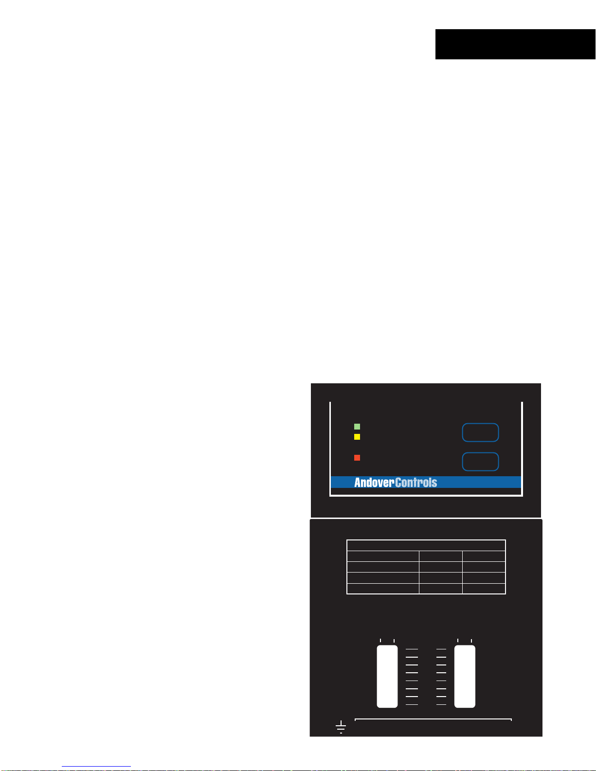
Status/Control P a nel
Status In dic a t or s
The DI-6-A C module includes a c om plete indicator st atus panel on the front of the
module.
POWER
COMM
STATUS
INPUT
1
2
3
4
INPUT
5
6
COMMISSION
RESET
DI-6
This panel includes indicators reporting on the status of the following:
POWER
COMM
STATUS
This green indicat or illum inates when DC power is applied through the
Power/IO Bus .
This yellow indicat or illum inates when data is tr ans m itt ed from the
module to the Net Controller. In normal operation, data is only transmit ted
when an input value changes.
This indicator will als o flash periodically as t he NetController check s the
I/O bus periodically .
This red indicat or is nor m ally off . If it is alway s on or flas hing at a fast
rate there is a problem wit h the module.
This indicator c an be m anually illum inated from the Continuum
workstation and used as a troubleshooting aid when locat ing a particular
module. More inf or m ation on using this indicator may be found in t he
INPUT
Troubleshooting
These red indicat or s ( one for eac h c hannel) illum inate when an ‘ON’
section of this manual.
condition is sensed.
40
Andover Controls
Technical Manuals Online! - http://www.tech-man.com
Page 47

This panel also includes two operator swit c hes that perfor m the f ollowing:
DI-6-AC
COMMISSION
RESET
After phy s ic al installation and during configurat ion through the
Continuum workstation, pressing this button registers the module’s
address with t he s yst em. For m or e information, refer to the section on
Configuring I/ O
found earlier in this manual.
Should the module become inoper able, pressing this button resets the
module. It does not er as e its m emory.
Technical Manuals Online! - http://www.tech-man.com
Continuum I/O System Reference
41
Page 48

42
Andover Controls
Technical Manuals Online! - http://www.tech-man.com
Page 49
The DI-8, Continuum ’s digital input module, is us ed for c os t-effective sensing of multiple
dry digital inputs in applic ations such as equipment s tatus monitoring or alarm point
monitoring. The DI-8 has eight digital input seach can be software configured to accept
a digital (contac t closure or 0-5 volt input ) or counter signal. Counter fr equenc y is 10Hz
on all eight inputs. In addition, high speed counting up to 10KHz max. is available (via a
DIP switc h) on Channels 1 and 2 f or high-speed m etering and industrial applications.
40V transient s uppr es s or s on all eight inputs protect against high v oltage short duration
transients ev ents. The DI-8 is designed to accept dry contact inputs or 0-5 volts and can
withstand up t o 24 VAC/ DC continuous v oltage on four channels.
FEATURES
POWER
COMM
STATUS
INPUT
INPUT
1
5
6
7
8
COMMISSION
RESET
Allows interf ac e to relay contact closures or 0- 5v
•
digital signals.
2
3
4
DI-8
DI-8
USE COPPER CONDUCTORS ONLY
USE COPPER CONDUCTORS ONLY
READER
HIGH SPEED
POWER
COUNTER
+ 5V, 100mA
OFF ON
+ 12V, 180mA
READER
+
INPUTS: 0-5V/DRY CONTACTS
G
DC
A
N
V
L
T
D
K
A
/
/
1
0
IN1
IN3 IN4 RETIN2 RET IN5 IN6 RET IN7 IN8 RET
123456789101112
4
12
3
1-DOOR
ON
OFF
AUTO
IN1
SUPERVISED
IN2
INPUTS(0-5V)
1
23
L
E
D
R
A
R
O
D
DIGITAL / COUNTER INPUTS
56
E
U
E
O
T
X
X
R
7
10 11 12
9
8
OUT 2
ON
OFF
AUTO
CONTACT RATING:
24VAC/DC, 5A
DIGITAL OUTPUTS
1-DOOR
13 14 15
OUT2
Allows high speed counting on c hannels 1 and 2.
•
Input prot ec tion allows accidental wiring of
•
24VAC to inputs .
Technical Manuals Online! - http://www.tech-man.com
Continuum I/O System Reference
43
Page 50

DI-8
SPECIFICATIONS
ELECTRICAL
Power Consumption:
0.8 Watt at 24VDC max.; normally provided by
supply module.
Continuum
power
Overload Protection:
INPUTS
Number of Inputs:
Input Types:
Input Protection:
Input Impedance:
Input Connections:
Digital:
Input Type:
Pulse Width:
Curren t:
Counter:
Input Type:
Channels 1 and 2 in HI-speed mode:
Frequency:
Pulse Width:
Current:
0.5A resettable fuse with transient voltage suppressor (TVS) and
reverse polarity protection.
8 Digital inputs
Digital or Cou nte r, software selectab le
24V AC/DC applied to 4 channels max.
(40V transient protection on each input)
10KΩ pull-up resistor referenced to +5 volts
Two-piece, 13-position removable terminal block
Contact closure or 0-5V input
50 ms min imum
0.5mA
Contact closure or 0-5V input
10KHz max.
50 µs min.
0.5mA
Channels 3 through 8; and Channel 1 and 2 in LO-speed mode:
Frequency:
Pulse Width:
Curren t:
44
Andover Controls
10Hz max.
50 ms min.
0.5mA
Technical Manuals Online! - http://www.tech-man.com
Page 51
I/O Connections
The actual input connect ions are located on a twelve-position removable screw terminal
connector located at the bottom of the module. Input wir es s hould enter from either the
top or bott om wiring t r oughs , and should c om e from the left side of the rack (by
convention).
The inputs are labeled IN1, IN2, IN3, and so fort h. Eac h pair of inputs is followed by a
connection labeled RET for the input signal retur n, resulting in a sequence of I N1, I N2,
RET, IN3, IN4, RET, and s o on. F or any given input, you should use the closest r eturn
terminal either before or after that input —the nex t return terminal goes with t he next two
inputs, and so on.
The twelve-pos ition connector allows for eight inputs and four signal ret ur ns .
The diagram below indicat es wher e eac h input number is located in the terminal block.
DI-8
Shield/Eart h Ground
1.
2.
3.
4.
5.
6.
7.
8.
9.
IN 1
IN 2
RETURN
IN 3
IN 4
RETURN
IN 5
IN 6
RETURN
10. IN 7
11. IN 8
12. RETURN
POWER
COMM
STATUS
INPUT
1
2
3
4
INPUT
5
6
7
8
COMMISSION
RESET
DI-8
USE COPPER CONDUCTORS ONLY
USE COPPER CONDUCTORS ONLY
1-DOOR
ON
OFF
AUTO
READER
POWER
HIGH SPEED
COUNTER
+ 5V, 100mA
OFF ON
+ 12V, 180mA
READER
+
V
IN1
123456789101112
12
INPUTS: 0-5V/DRY CONTACTS
G
DC
A
N
L
T
D
K
A
/
/
1
0
4
3
IN1
SUPERVISED
IN2
INPUTS(0-5V)
1
23
L
E
D
A
O
D
DIGITAL / COUNTER INPUTS
U
O
X
R
IN3 IN4 RETIN2 RET IN5 IN6 RET IN7 IN8 RET
56
7
R
R
E
E
T
X
9
8
CONTACT RATING:
24VAC/DC, 5A
DIGITAL OUTPUTS
1-DOOR
10 11 12
OUT 2
ON
OFF
AUTO
OUT2
13 14 15
Technical Manuals Online! - http://www.tech-man.com
Continuum I/O System Reference
45
Page 52
DI-8
High Speed Counter S election Switches
The DI-8 input module allows input c hannels 1 and 2 to be configured with the capability
of counting input puls es or c ontact closures at a rate of up to 10KHz. A select ion s witch is
included for each of these two input channels. This s witch allows you to select whether or
not you want the high speed input c onnec ted. A small 2-position s witch module is
accessible fr om the front of the module when the door is opened.
Slide marker
moves left and right
1
2
O
N
These switc h modules are c om m only c alled “ DIP Switches” and require a small object
such as the tip of a pen or a small screwdriver to operate them. Each switch position acts
as a “slide switc h” . Pr es s ing the rais ed s lide m ar k er to t he side mark ed “ ON” c los es or
enables the switc h thereby enabling high speed counting. To open or disable the s witch
position, pres s the slide marker over to the “OFF” side.
46
Andover Controls
Technical Manuals Online! - http://www.tech-man.com
Page 53

Input Circuitry
The following is a sim plified schematic of t he DI-8 Digital Input module:
5V
10K
5V
DI-8
IN x
RET
Channels 1 and 2 can be configured to allow high speed counting. The switches on the
front of the module substitute different value components for the low pass filt er formed by
the combination of R and C. These values support higher frequency inputs.
R
II
C
Technical Manuals Online! - http://www.tech-man.com
Continuum I/O System Reference
47
Page 54
DI-8
Sensing Digital Inputs or Contact Closures
Digital input points ar e des igned to provide an ON or OFF reading of a signal ( wir ed
between the input and r eturn).
Digital logic
Signal
IN x
RET
IN x
Contact
Closure
RET
To sense a digital input or contact closure, c onfigure an input point with an Electrical
Type of
Digital
.
A digital input is c ons ider ed “ ON” whenever the voltage acr os s its input meets or exceeds
the ON Threshold. For a c ontact closure, this is 0 (zero) volt s. S im ilar ly , an OFF condition
meets, or is lower than, the Off Threshold. With a contact closure, this is the value of
Vref.
: When configuring a Digital point, ther e is a ‘Polarity’ attribute. If this att r ibute is
Note
enabled, readings are rev er s ed: ‘On’ will occur when t he input is at Vref because the
contact is open, and ‘O ff ’ oc c ur s when the input is at 0 volts because the contact is
closed.
48
Andover Controls
Technical Manuals Online! - http://www.tech-man.com
Page 55

Counting Pulsing Signals or Contact Closures
Counter inputs ar e des igned to allow the monitoring of digital pulse trains or cont act
closures acros s an input just like digital inputs, but they accumulate a total of those
closures and act lik e a c ounter.
Interf ac ing is s im ilar to a digit al input, however, you set the Elect r ic al Type attribute to
DI-8
Counter
When using an input as a counter , you must take into account the fr equenc y of t he input
signal being counted. Inputs 3-8 do not allow for v er y high speed contact counting. T hes e
channels allow counting up t o a m ax im um of 10 Hz or 10 cont act c los ur es or digital
pulses per second.
In high-speed mode, c hannels 1 and 2 c an be c onfigured (via front panel switch) to count
to a maximum of 10Khz or 10, 000 c ontact closures or digital pulses per s ec ond.
instead.
Counter Dut y Cycle
To achieve the m ax imum counter frequency, the amount of time t he signal is O N as
opposed to being OF F must be at least 125 milliseconds.
Technical Manuals Online! - http://www.tech-man.com
Continuum I/O System Reference
49
Page 56
DI-8
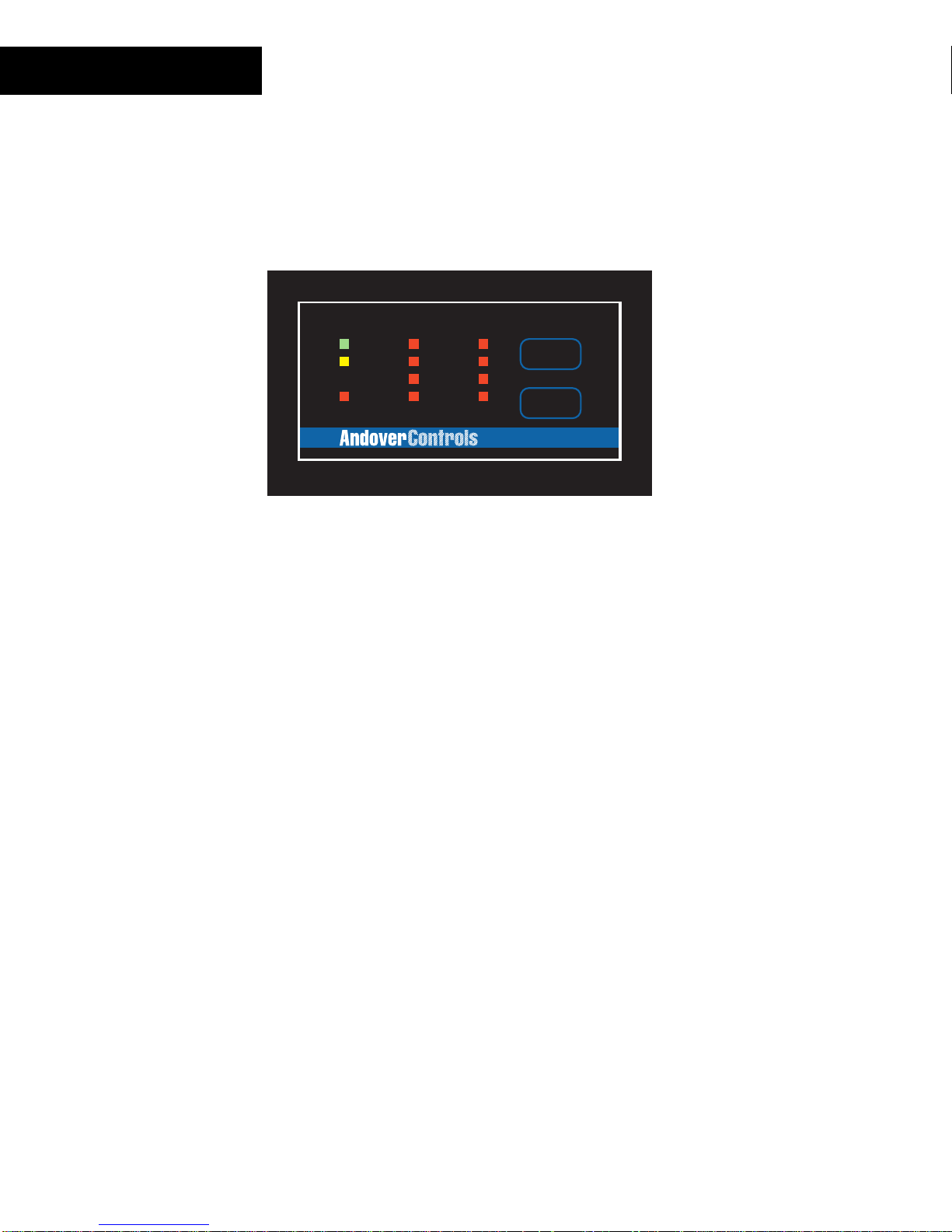
Status/Control P a nel
Status In dic a t or s
The DI-8 module includes a com plete indicator st atus panel on the front of the module.
POWER
COMM
STATUS
INPUT
1
2
3
4
INPUT
5
6
7
8
COMMISSION
RESET
DI-8
This panel includes indicators reporting on the status of the following:
POWER
This green indicat or illum inates when DC power is applied through the
Power/IO Bus .
COMM
This yellow indicat or illum inates when data is tr ans m itt ed from the
module to the Net Controller. In normal operation, data is only transmit ted
when an input value changes.
This indicator will als o flash periodically as t he NetController check s the
I/O bus periodically .
STATUS
This red indicat or is nor m ally off . If it is alway s on or flas hing at a fast
rate there is a problem wit h the module.
This indicator c an be m anually illum inated from the Continuum
workstation and used as a troubleshooting aid when locat ing a particular
module. More inf or m ation on using this indicator may be found in t he
INPUT
Troubleshooting
These red indicat or s ( one for eac h c hannel) illum inate when an ‘ON’
section of this manual.
condition is sensed.
50
Andover Controls
Technical Manuals Online! - http://www.tech-man.com
Page 57

This panel also includes two operator swit c hes that perfor m the f ollowing:
DI-8
COMMISSION
RESET
After phy s ic al installation and during configurat ion through the
Continuum workstation, pressing this button registers the module’s
address with t he s yst em. For m or e information, refer to the section on
Configuring I/ O
found earlier in this manual.
Should the module become inoper able, pressing this button resets the
module. It does not er as e its m emory.
Technical Manuals Online! - http://www.tech-man.com
Continuum I/O System Reference
51
Page 58

52
Andover Controls
Technical Manuals Online! - http://www.tech-man.com
Page 59

The MI-6, Cont inuum ’s m illiam p input module, allows for a direct connection of a 2-wire
0-20mA or 4-20mA sensor to any of the module’s six inputs. The need for an exter nal
resistor and an ex ternal power supply are eliminated. The MI-6 module is a perfect mat c h
for temper ature transmitters, humidity and pressure transduc er s , gas m onitors, and other
industry-standard sensors with either a 0-20mA or 4-20mA output. The six inputs on the
MI-6 module have a 0- 20m A range and 10 bit A/D c onv er s ion.
FEATURES
EXTERNAL
POWER
COMM
STATUS
USE COPPER CONDUCTORS ONLY
USE COPPER CONDUCTORS ONLY
ON
OFF
AUTO
1-DOOR
COMMISSION
RESET
MI-6
ON
OFF
AUTO
OUT 2
6 current meas ur ing Inputs
•
0-20mA Range
•
10 Bit A/D Convert er
•
MI-6
READER
POWER
+ 5V, 100mA
INPUT RANGE: 0 - 20mA
SENSOR VOLTAGE: 24VDC
+ 12V, 180mA
SUPERVISED
READER
+
G
N
V
D
IN1
+ -
123456789101112
12
INPUTS(0-5V)
MILLIAMP INPUTS
1
L
DC
A
E
L
A
T
D
IN2 IN3 IN4 IN5 IN6
K
A
U
X
/
/
+ -
+ -
1
0
4
56
3
23
D
O
O
R
7
R
R
E
E
T
X
+ -
9
8
CONTACT RATING:
24VAC/DC, 5A
DIGITAL OUTPUTS
1-DOOR
+ - + -
10 11 12
13 14 15
OUT2
Technical Manuals Online! - http://www.tech-man.com
Continuum I/O System Reference
53
Page 60

MI-6
SPECIFICATIONS
ELECTRICAL
Power Consumption:
3.8 Watts at 24VDC max.; normally provided by
power supply module (including up to 20mA senso r power
for each input).
Continuum
Overload Protection:
INPUTS
Number of Inputs:
Input Range:
Resolution:
Accuracy:
Drift:
Input Resistance:
Maximum Input Current:
Voltage Supply to Sensors:
Input Protection:
Input Connections:
0.5A resettable fuse with transient voltage suppressor
(TVS) and reverse polarity protection.
6 Milliamp inputs
0-20 mA
20 µA
±80 µA max.
±50ppm/DegC max.
249Ω, 0.1%
±30 mA
19.0 to 26.0V (varies with +24V DC input voltage)
Each input and the Sensor voltage output includes a
transient voltage suppressor (TVS) and a resettable fuse.
Two-piece, 13-position removable terminal block
54
Andover Controls
Technical Manuals Online! - http://www.tech-man.com
Page 61

I/O Connections
The actual input connect ions are located on a thirteen-position removable screw terminal
connector located at the bottom of the module. Input wir es s hould enter from either the
top or bott om wiring t r oughs , and should c om e from the left side of the rack (by
convention).
The inputs are labeled IN1, IN2, IN3, and so fort h. Eac h input occ upies a pair of
terminals, r es ulting in a sequence of IN1+, IN1-, IN2+, IN2-, and so on. For any given
input, observ e the polarity for that input , + connec ts to the Supply terminal of the input.
The minus terminal connec ts to the Signal input.
The diagram below indicat es wher e eac h input number is located in the terminal block.
Shield/Eart h Ground
IN 1 +
1.
IN 1 -
10.
11.
12.
2.
3.
4.
5.
6.
7.
8.
9.
IN 2 +
IN 2 IN 3 +
IN 3 IN 4 +
IN 4 IN 5 +
IN 5 IN 6 +
IN 6 -
POWER
COMM
STATUS
EXTERNAL
USE COPPER CONDUCTORS ONLY
USE COPPER CONDUCTORS ONLY
1-DOOR
ON
OFF
AUTO
COMMISSION
RESET
MI-6
OUT 2
ON
OFF
AUTO
MI-6
Technical Manuals Online! - http://www.tech-man.com
READER
POWER
+ 5V, 100mA
INPUT RANGE: 0 - 20mA
SENSOR VOLTAGE: 24VDC
+ 12V, 180mA
READER
+
G
DC
A
N
V
T
D
IN1
A
/
+ -
1
123456789101112
12
3
SUPERVISED
INPUTS(0-5V)
MILLIAMP INPUTS
1
23
L
E
A
D
U
X
+ -
56
D
O
O
R
7
L
IN2 IN3 IN4 IN5 IN6
K
/
+ -
0
4
R
E
X
8
R
E
T
+ -
9
CONTACT RATING:
24VAC/DC, 5A
DIGITAL OUTPUTS
1-DOOR
+ - + -
10 11 12
13 14 15
OUT2
Continuum I/O System Reference
55
Page 62

MI-6
Input Circuitry
The following is a sim plified schematic of t he MI- 6 Milliamp I nput module:
24V
300mA
Resettable
Fuse
5V
100mA
Resettable
Fuse
249
Ω
R
C
To
Analog/Digital
Converter
All six input pairs inc lude their own automatic ally r es ett able fuses. These devices are
designed to open when sensing an over-current. T hey reset when the current supplied is
within range.
Note: In some extreme inst ances, the fuses may require that you remove power to
the module tempo rarily to reset their state.
56
Andover Controls
Technical Manuals Online! - http://www.tech-man.com
Page 63

Sensing Current
The current supplying sens or is c onnec ted as indicated in the following illustration:
Supply
24V
Loop-Powered
Sensor
Signal
INx
MI-6
To measure cur r ent on an input , configure an input point wit h an Elect r ic al Type of
Current
.
Technical Manuals Online! - http://www.tech-man.com
Continuum I/O System Reference
57
Page 64

MI-6
Status/Control P a nel
Status In dic a t or s
The MI-6 module includes a c om plete indicator st atus panel on the front of the module.
POWER
COMM
STATUS
EXTERNAL
COMMISSION
RESET
MI-6
This panel includes indicators reporting on the status of the following:
POWER
This green indicat or illum inates when DC power is applied through the
Power/IO Bus .
COMM
This yellow indicat or illum inates when data is tr ans m itt ed from the
module to the Net Controller. In normal operation, data is only transmit ted
when an input value changes.
This indicator will als o flash periodically as t he NetController check s the
I/O bus periodically .
STATUS
This red indicat or is nor m ally off . If it is alway s on or flas hing at a fast
rate there is a problem wit h the module.
This indicator c an be m anually illum inated from the Continuum
workstation and used as a troubleshooting aid when locat ing a particular
module. More inf or m ation on using this indicator may be found in t he
EXTERNAL
Troubleshooting
This green indicat or illum inates when 24V DC power is available t o
section of this manual.
external sensor s .
58
Andover Controls
Technical Manuals Online! - http://www.tech-man.com
Page 65

This panel also includes two operator swit c hes that perfor m the f ollowing:
MI-6
COMMISSION
RESET
After phy s ic al installation and during configurat ion through the
Continuum workstation, pressing this button registers the module’s
address with t he s yst em. For m or e information, refer to the section on
Configuring I/ O
found earlier in this manual.
Should the module become inoper able, pressing this button resets the
module. It does not er as e its m emory.
Technical Manuals Online! - http://www.tech-man.com
Continuum I/O System Reference
59
Page 66

60
Andover Controls
Technical Manuals Online! - http://www.tech-man.com
Page 67

DM-20
The DM-20, Continuum’s Digital Input and Output m odule, provides high density,
versatile I /O for m any cont r ol applic ations. When coupled with t he optional DIO-20
Expansion Board, the DM-20 allows you to mix and match up to 20 digital inputs and
outputs. Us ing standar d off-the-shelf digital I/O blocks, the DIO-20 allows the system
designed to meet a wide r ange of applications, inc luding ON-OFF or pulse-width
modulation (PW M ) cont r ol of equipment and for switching induct iv e loads up to 240VAC.
The DM-20 provides 24 V DC power to the DIO- 20 v ia a separat e c able as s em bly .
When used without the DIO- 20 E x pans ion B oar d, the DM-20 can control any combination
of inputs and out puts, up to a total of 20 per module. The DM-20 can be used to
drive/sense up to 20 LEDs and/or switches on the Continuum enclosure’s door-mount ed
GA-40 or GA-80 Graphic Annunciator Panel via an easy-to-use 25-pin cable assembly
and built-in terminal blocks.
FEATURES
READER
POWER
24VDC @ .36 Amps
+
TO DI0-20
V
+
-
12
12
POWER
COMM
STATUS
USE COPPER CONDUCTORS ONLY
USE COPPER CONDUCTORS ONLY
ON
OFF
AUTO
+ 5V, 100mA
+ 12V, 180mA
READER
G
DC
A
N
T
D
A
/
1
3
L
K
/
0
4
D CONNECTOR
I/O I/O I/O I/O I/O
I/O
I/O
SUPERVISED
14
15 16 17 18 19 20
INPUTS(0-5V)
1
23
L
E
D
A
R
O
D
U
E
O
X
X
R
I/O I/O I/O I/O I/O I/O I/O I/O
I/O
I/O
1
2 3 4 5 6 7 8 9 10 11 12 13
56
7
8
1-DOOR
CONTACT RATING:
24VAC/DC, 5A
DIGITAL OUTPUTS
1-DOOR
R
E
T
10 11 12
9
COMMISSION
RESET
DM-20
ON
OFF
AUTO
G
G
G
N
N
N
D
D
D
OUT 2
G
N
D
I/O
I/O I/O
13 14 15
G
N
OUT2
20 General Purpose Digital Inputs/Outputs
•
Each point may be configur ed as an input or an
•
output
Direct connection to DIO-20 Expansion Module
•
Direct connection to GA-40/80 Graphic
•
Annunciator Panels .
D
Technical Manuals Online! - http://www.tech-man.com
Continuum I/O System Reference
61
Page 68

DM-20
SPECIFICATIONS
ELECTRICAL
Power Consumption:
0.5 watt at 24VDC max; provided by Continuum power
supply module.
Up to 9 watts at 24VDC when the DIO-20 is powered from
the DM-20 .
External Power Connector:
Overload Protection:
LED Power Supply:
INPUTS/OUTPUTS 20 total points; user-selectable channel-by-channel as
Inputs:
Input Type: w/DIO-20 w/o DIO-20
Pulse Width:
Outputs:
Output Type: w/DIO-20 w/o DIO-20
Three-position removable connector
0.5A resettable fuse with transient voltage suppressor
(TVS) and reverse polarity protection for both DM-20 power
and DIO-20 power.
Customer-provided external 5V power supply when using
the DM-20 to drive LEDs.
inputs or outputs
24 VDC logic voltage (DIO-20). 0-5 VDC
Input rating depends on input
module(s) selected.
125 ms min. 125 ms min.
5 VDC logic voltage. Open- collector Output
Range depends on output transistor with series
module selected. 330 ohm 1/8 W resistor;
5 VDC max., 15 mA
Output Resolution:
Output Protection:
I/O Connections:
62
Andover Controls
0.1 sec. For Pulse Width Modulation (PWM) control
Transient voltage suppressor (TVS) and current limiting
resistor on each channel.
25-position DB25 Female and one removable three-
terminal block.
Technical Manuals Online! - http://www.tech-man.com
Page 69
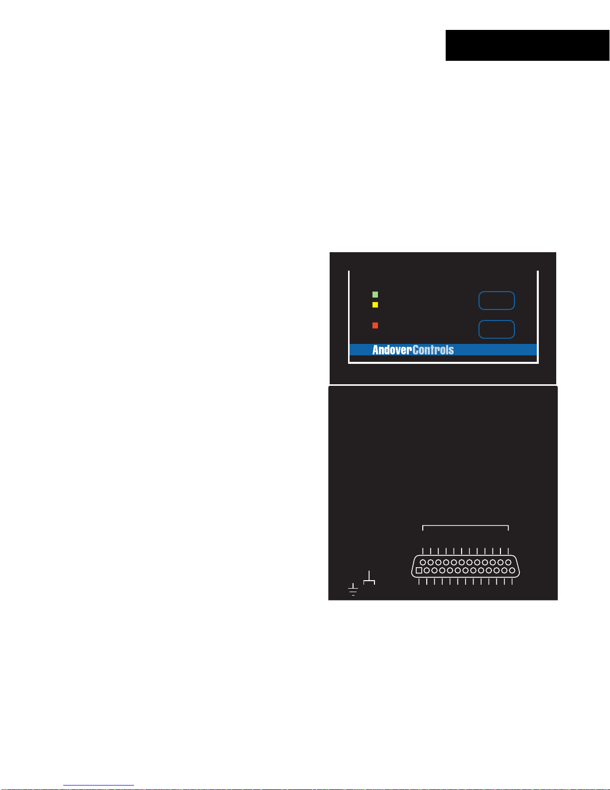
DM-20
I/O Connections
The actual I/O connec tions are located on a 25-position DB 25- type female connector
located at the bottom of the module. A separate three-conductor removable screw
connector prov ides 24V DC power to external devices.
The inputs are labeled I/O1, I/O2, I/O3, and so f orth. Each input/output occupies a s ingle
position of t he c onnec tor. Five signal ground pins are supplied as well.
The diagram below indicat es wher e eac h input number is located on the module.
1 Shield/Eart h Ground
2 + 24VDC @ .36 Amps
3 24 V Return
POWER
COMM
COMMISSION
25-Pin D Connector
I/O 1
1.
I/O 2
2.
I/O 3
3.
I/O 4
4.
I/O 5
5.
I/O 6
6.
I/O 7
7.
I/O 8
8.
I/O 9
9.
10. I/O 10
11. I/O 11
12. I/O 12
13. I/O 13
14. I/O 14
15. I/O 15
16. I/O 16
17. I/O 17
18. I/O 18
19. I/O 19
20. I/O 20
21. Ground
22. Ground
23. Ground
24. Ground
25. Ground
STATUS
READER
POWER
24VDC @ .36 Amps
+
TO DI0-20
V
+
-
12
12
USE COPPER CONDUCTORS ONLY
USE COPPER CONDUCTORS ONLY
1-DOOR
ON
OFF
AUTO
+ 5V, 100mA
+ 12V, 180mA
READER
G
DC
A
N
T
D
A
/
1
3
L
K
/
0
4
L
E
D
I/O
1
56
D CONNECTOR
I/O I/O I/O I/O I/O
I/O
I/O
SUPERVISED
14
15 16 17 18 19 20
INPUTS(0-5V)
1
23
D
A
R
O
U
E
O
X
X
R
I/O I/O I/O I/O I/O I/O I/O I/O
I/O
2 3 4 5 6 7 8 9 10 11 12 13
7
8
DM-20
CONTACT RATING:
G
G
24VAC/DC, 5A
N
N
D
D
DIGITAL OUTPUTS
1-DOOR
R
E
T
10 11 12
9
RESET
ON
OFF
AUTO
G
N
D
I/O
OUT 2
G
G
N
N
D
D
OUT2
I/O I/O
13 14 15
Technical Manuals Online! - http://www.tech-man.com
Continuum I/O System Reference
63
Page 70
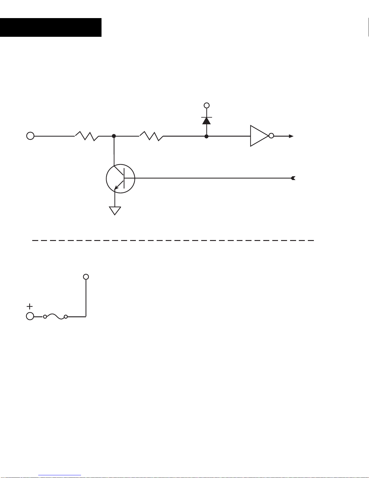
DM-20
Input/Ou tput Circuitry
The following is a sim plified schematic of each DM - 20 Input /O utput channel:
I/O x
330
II
I/O Channel (same for all 20 channels)
24V
500mA
Resettable
Fuse
All 20 I/O channels r es em ble the circuit shown above.
The 24VDC power available t o ex ternal devices includes an automatically res ett able
fuse. This f us e is designed t o open when an ex ternal device tries to extr ac t mor e c ur r ent
than is available. They reset when the curr ent draw is bac k within r ange.
Note: In some extreme inst ances, the fuses may require that you remove power to
the module tempo rarily to reset their state.
64
Andover Controls
Technical Manuals Online! - http://www.tech-man.com
Page 71
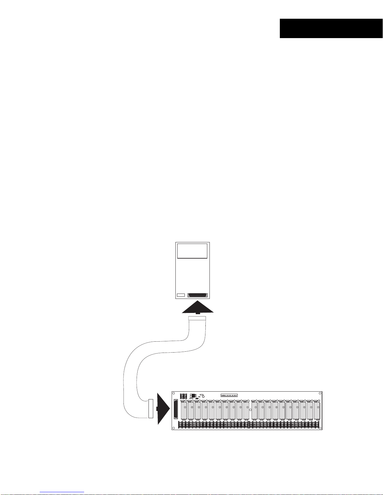
DM-20
Using the DM-20
The DM-20 is prim ar ily des igned to directly interf ac e with t he DIO-20 or the G A-40 / GA80 Graphic Annunciator Panels. However , it can also be used as a general purpose
digital I/O module containing 20 points .
DIO-20 Interface
The DIO-20 Expans ion M odule pr ov ides a c onnec tion for up to 20 solid state input or
output modules for the I/O channels of the DM-20. It includes indiv idually fused sockets
for modules f r om manuf actur er s s uc h as Opto 22, Gr ay hill, Gordos, Crydom and Potter &
Brumfield. Y ou c an mix input and output modules on the DIO-20 as needed.
The connection between the DM-20 and the DIO-20 cons is ts of a 25-pin r ibbon c able to
supply data between the modules and a two-conduc tor power cable.
Data connection between the two is accomplished v ia a 25- pin m ale- m ale DB 25 c able:
DM-20
DM-20 to DIO-20
Data Connection
DIO-20
Technical Manuals Online! - http://www.tech-man.com
Continuum I/O System Reference
65
Page 72
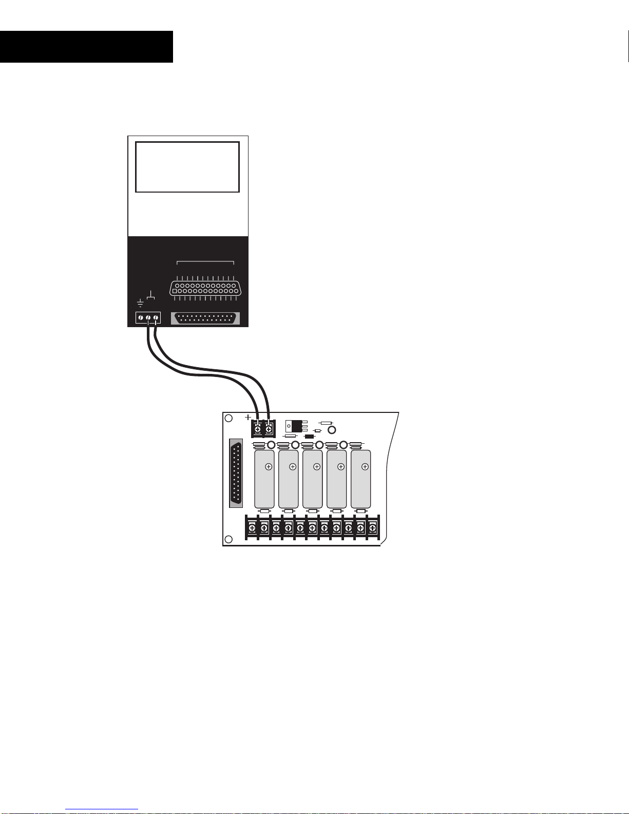
DM-20
The Power connection between the DIO-20 and the DM- 20 is via a two-conduc tor cable
assembly as shown:
DM-20
D CONNECTOR
G
G
G
G
G
N
N
N
N
N
D
D
D
D
D
I/O
I/O I/O
DM-20 to DIO-20
DC Power Connection
24VDC @ .36 Amps
TO DI0-20
+
-
12
I/O I/O I/O I/O I/O
I/O
I/O
14
15 16 17 18 19 20
I/O I/O I/O I/O I/O I/O I/O I/O
I/O
I/O
1
2 3 4 5 6 7 8 9 10 11 12 13
+24 V Return
+24 VDC
DIO-20
Using the DM-20/ DIO - 20 Combination
The DIO-20 provides the DM-20 with a real-world inter face to its I/O channels. Solid-s tate
input modules (on t he DIO - 20) pr ov ide interface circuitr y to a variet y of signals . These
modules convert their signals to digital levels for input to the DM-20.
Similarly, s olid- s tate output modules (on the DIO-20) allow the digital levels of the DM-20
to interf ac e to a var iety of signals .
In both cases, the I/O points are set up to have an Electric al Type of
what type of solid-s tate module is installed.
For more inf ormat ion on the DIO-20, refer to its User Manual.
66
Andover Controls
Technical Manuals Online! - http://www.tech-man.com
Digital
no matter
Page 73
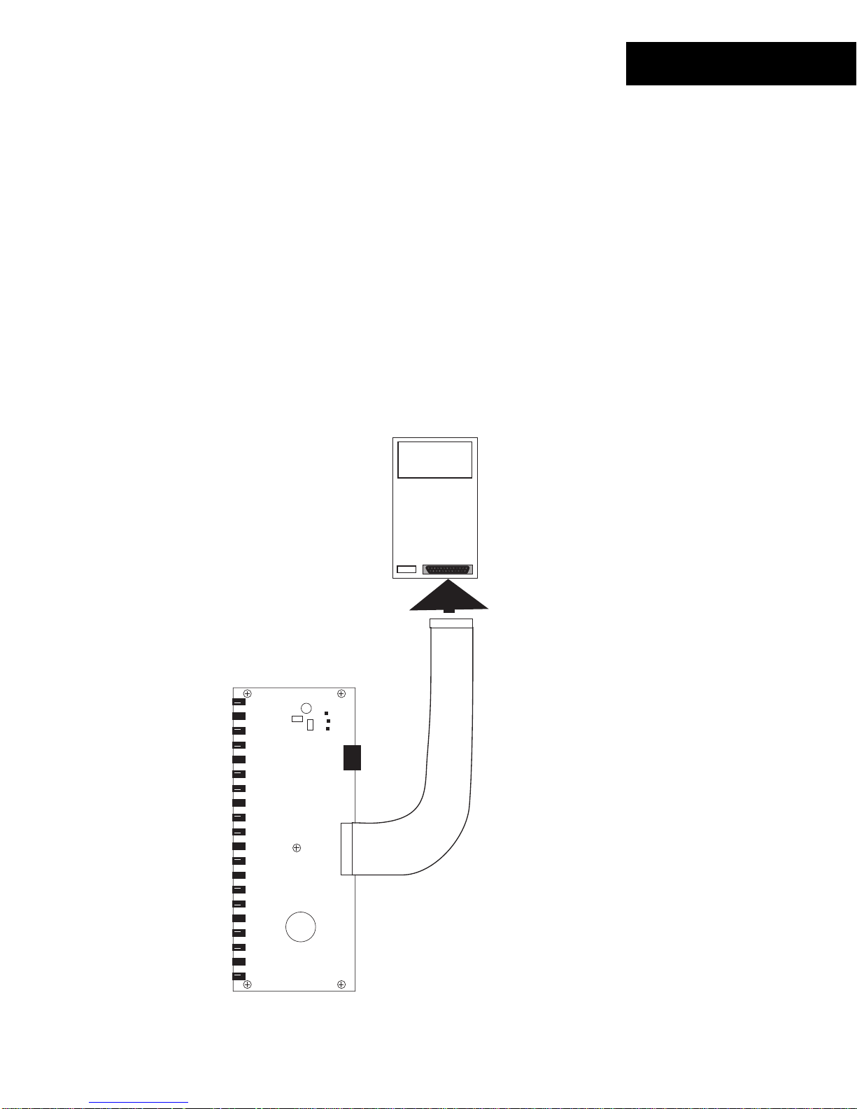
DM-20
GA-40/ GA-80 Int erf ace
The GA-40 and GA-80 Gr aphic A nnunc iator Panels provide the capabilit y of creating
custom display and c ontrol panels attached to the Cont inuum NE M A enclosur e or to an
auxiliary panel. T hes e panels pr ov ide a c onnec tion for up to 40 (GA-40) or 80 (GA - 80)
input switches or output LEDs. You can mix the number of switches and LE Ds as
needed.
The connection between the DM-20 and the GA-40 and GA-80 panels c ons is ts of a 25pin ribbon cable to supply data between the modules and a three-conductor power cable.
Data connection between the two is accomplished v ia a 25- pin m ale DB 25 c able that is
permanently at tached to the GA panels.
The GA-40 provides interfaces for 2 DM-20 modules. The GA-80 provides interfaces for
up to 4 DM-20 modules.
GA-40/80
DM-20
DM-20 to GA-40/80
Data Connection
Technical Manuals Online! - http://www.tech-man.com
Continuum I/O System Reference
67
Page 74

DM-20
The Power connection between the GA-40/ 80 modules and t he DM - 20 is via a threeconductor cable as s em bly as s hown:
DM-20
D CONNECTOR
G
G
G
G
G
N
N
N
N
N
D
D
D
D
D
I/O
I/O I/O
DM-20 to GA-40/80
DC Power Connection
24VDC @ .36 Amps
TO DI0-20
+
-
12
I/O I/O I/O I/O I/O
I/O
I/O
14
15 16 17 18 19 20
I/O I/O I/O I/O I/O I/O I/O I/O
I/O
I/O
1
2 3 4 5 6 7 8 9 10 11 12 13
+24 V Return
Chassis Gnd
Chassis Ground
+24 VDC
24 V Return
GA-40/80
Using the DM-20/GA- 40/80 Combination
The GA-40/80 ser ies of modules pr ov ide the DM-20 with an easy to configure panel
interface to its I/O channels. Switches ( c onnec ted to the GA-40/80) provide user inputs to
the DM-20.
Similarly, LE Ds ( c onnec ted to the GA-40/80) allow the digital lev els of the DM-20 to
display a variety of conditions.
In both cases, the I/O points are set up to have an Electric al Type of
what type of device is ins talled.
For more inf ormat ion on the GA-40/80, refer to its section found in the
Module Reference
68
Andover Controls
Manual.
Technical Manuals Online! - http://www.tech-man.com
Digital
no matter
Continuum Display
Page 75

DM-20
General Purpo se DM - 20 Digit al Int erf ace
The DM-20 can be used to prov ide 20 gener al pur pos e digital inputs and output s . I t is not
necessary t o interface the module with an exter nal ex pans ion pr oduc t to use its
capabilities. E ac h c hannel c an be us ed to output as digital signal or r ead a digital signal
or contact closure. Set the Electrical Type t o
Digital
The DM-20 can be configured as a gener al pur pos e digital input. With the addition of an
external ref er enc e pull- up r es is tor, it can be used for sensing c ontact closures as shown
below:
.
5V
10K
Digital logic
Signal
I/O x
GROUND
I/O x
Contact
Closure
GROUND
As a digital output, the DM-20 presents an open collec tor load directly on the out put
terminal. Connec t digital devices and LED indic ators as shown below:
Digital logic
Input
5V
Resistor value determined
according to the
current requirements
of the LED
10K
LED
Indicator
I/O x
+V
I/O x
GROUND
Technical Manuals Online! - http://www.tech-man.com
GROUND
Continuum I/O System Reference
69
Page 76

DM-20
Status/Control P a nel
Status In dic a t or s
The DM-20 module includes a c om plete indicator status panel on the front of the module.
POWER
COMM
STATUS
COMMISSION
RESET
DM-20
This panel includes indicators reporting on the status of the following:
POWER
This green indicat or illum inates when DC power is applied through the
Power/IO Bus .
COMM
This yellow indicat or illum inates when data is tr ans m itt ed from the
module to the Net Controller. In normal operation, data is only transmit ted
when an input value changes.
This indicator will als o flash periodically as t he NetController check s the
I/O bus periodically .
STATUS
This red indicat or is nor m ally off . If it is alway s on or flas hing at a fast
rate there is a problem wit h the module.
This indicator c an be m anually illum inated from the Continuum
workstation and used as a troubleshooting aid when locat ing a particular
module. More inf or m ation on using this indicator may be found in t he
70
Andover Controls
Troubleshooting
section of this manual.
Technical Manuals Online! - http://www.tech-man.com
Page 77

This panel also includes two operator swit c hes that perfor m the f ollowing:
DM-20
COMMISSION
RESET
After phy s ic al installation and during configurat ion through the
Continuum workstation, pressing this button registers the module’s
address with t he s yst em. For m or e information, refer to the section on
Configuring I/ O
found earlier in this manual.
Should the module become inoper able, pressing this button resets the
module. It does not er as e its m emory.
Technical Manuals Online! - http://www.tech-man.com
Continuum I/O System Reference
71
Page 78

72
Andover Controls
Technical Manuals Online! - http://www.tech-man.com
Page 79

AO-4-8
The AO-4-8, Continuum’s analog output m odule, has four analog outputs with eight-bit
resolution, whic h c an be c onfigured as either voltage (0-10VDC) or current (0-20m A )
outputs. The AO-4- 8 is the perfect choice for valves, dampers , variable speed drives, and
similar equipment that demand high contr ol ac c ur ac y.
An AO-4-8-O model with full override capabilities is als o av ailable. Each output c ontains
a three-posit ion m anual ov er r ide s witch and override potentiometer. In addit ion, the AO4-8-O provides s oft war e ov er r ide feedback to Andover’s
language for each output.
FEATURES
Plain English
programming
POWER
COMM
OVERRIDE
STATUS
USE COPPER CONDUCTORS ONLY
USE COPPER CONDUCTORS ONLY
MANUAL
AUTO
OFF
ADJUST
READER
POWER
OUT1
OUT2
MANUAL
OFF
AUTO
ADJUST ADJUST ADJUST
+ 5V, 100mA
CURRENT OUTPUT: 0 - 20mA, 650 OHMS MAX.
+ 12V, 180mA
VOLTAGE OUTPUT: 0 - 10V, 2K OHMS MIN.
READER
+
V
I
123456789101112
12
OUT1
L
G
DC
A
E
N
L
T
D
D
K
A
/
/
I
GND
V
1
0
4
56
3
1-DOOR
MANUAL
ON
OFF
OFF
AUTO
AUTO
MANUAL
SUPERVISED
INPUTS(0-5V)
ANALOG OUTPUTS
1
23
D
OUT2
A
R
O
U
E
O
X
X
R
GND
V
7
8
OUT3 OUT4
OUT3
R
E
T
I
V
10 11 12
9
COMMISSION
RESET
AO-4
OUT 2
MANUAL
ON
OFF
OFF
AUTO
AUTO
CONTACT RATING:
DIGITAL OUTPUTS
OUT2
1-DOOR
OUT4
I
GND
13 14 15
4 Analog Output s
•
8 bit Resolution
•
0-10V Voltage O utputs
•
0-20mA Current Out puts
•
AO-4-8-O Only:
Override T oggle S witches and Potentiomet er s
•
Override Det ec tion
•
GND
V
Technical Manuals Online! - http://www.tech-man.com
Continuum I/O System Reference
73
Page 80

AO-4-8
SPECIFICATIONS
ELECTRICAL
Power Consumption:
3.8 watts at 24VDC max; normally provided by Continuum
power supply module.
Overload Protection:
OUTPUTS
AO-4-8:
AO-4-8-O:
Output Protection:
Output Connections:
Output Types:
Voltage:
Range:
Resolution:
Accuracy:
Output Current:
0.5A resettable fuse with transient voltage suppressor
(TVS) and reverse polarity protection.
4 Analog outputs; 8 bit resolution
4 Analog outputs with overrides; 8 bit resolution
1/8 pico fuse per channel (40V TVS on each outputAO-4-
8-O model only)
Two-piece, 13-position removable terminal block
Voltage or current
0 to 10 V
0.05 V
±0.10V (1%FSR)
+5 mA (so urcing) -1 mA (sin k i n g)
2KΩ min.(sourcing)
0 to 20 mA
0.1 mA
±0.2 mA
650Ω max.
potentiometer on each output, with software feedback. LED
override status indicator.
Current:
Output Overrides: 3-position manual override switch and override
(AO-4-8-O only)
Output Connections: Two-piece, 13-position removable terminal block
74
Andover Controls
Load Resistance:
Range:
Resolution:
Accuracy:
Load Resistance:
Technical Manuals Online! - http://www.tech-man.com
Page 81

AO-4-8
I/O Connections
The actual output connections are locat ed on a thirt een-position removable screw
terminal connector located at the bottom of t he module. Output wires should enter from
either the t op or bottom wiring troughs, and should c om e from the r ight side of the rack
(by convention) .
The outputs ar e labeled OUT 1 I, OUT 1 V, OUT1 GND, and so forth. Each output
presents t wo way s of connect ing, resulting in a curr ent out put of OUT1 I and OUT1 GND,
and a voltage output between OUT1 V and OUT1 GND.
The diagram below indicat es wher e eac h output number is located in the terminal block.
Shield/Eart h Ground
OUT1 I
1.
OUT1 V
2.
OUT1 GND
3.
OUT2 I
4.
OUT2 V
5.
OUT2 GND
6.
OUT3 I
7.
OUT3 V
8.
OUT3 GND
9.
10. OUT4 I
11. OUT4 V
12. OUT4 GND
POWER
COMM
OVERRIDE
STATUS
USE COPPER CONDUCTORS ONLY
USE COPPER CONDUCTORS ONLY
OUT1
MANUAL
OFF
AUTO
ADJUST
READER
POWER
+
V
OUT1
I
123456789101112
12
OUT2
MANUAL
OFF
AUTO
ADJUST ADJUST ADJUST
+ 5V, 100mA
CURRENT OUTPUT: 0 - 20mA, 650 OHMS MAX.
+ 12V, 180mA
VOLTAGE OUTPUT: 0 - 10V, 2K OHMS MIN.
READER
G
DC
A
N
T
D
A
/
GND
V
1
3
ANALOG OUTPUTS
L
E
L
D
K
/
I
0
4
56
SUPERVISED
INPUTS(0-5V)
1
OUT2
A
U
X
V
MANUAL
ON
OFF
OFF
AUTO
AUTO
MANUAL
23
D
O
O
R
GND
7
R
E
X
8
1-DOOR
R
E
T
I
9
OUT3 OUT4
CONTACT RATING:
DIGITAL OUTPUTS
1-DOOR
OUT3
V
10 11 12
COMMISSION
RESET
AO-4
OUT 2
MANUAL
ON
OFF
OFF
AUTO
AUTO
I
GND
13 14 15
OUT2
OUT4
GND
V
Technical Manuals Online! - http://www.tech-man.com
Continuum I/O System Reference
75
Page 82
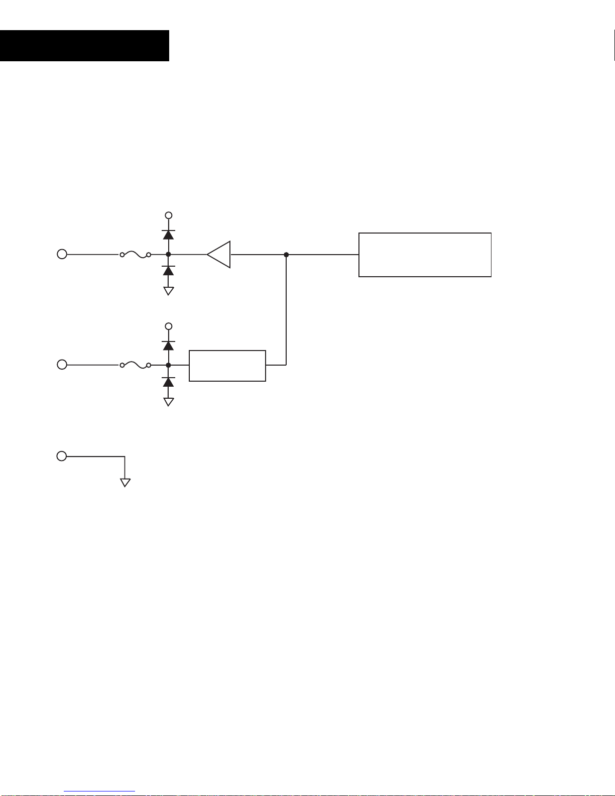
AO-4-8
Output Circuitry
The following is a sim plified schematic of each AO- 4- 8 Output c hannel:
24V
125mA
OUTx V
OUTx I
Resettable
Fuse
125mA
Resettable
Fuse
24V
Voltage to Current
Converter
Digital to Analog
Converter
GND
All 4 channels resemble the circuit shown above.
The outputs inc lude an automatically res ett able fuse. This fuse is designed to open when
an external device tries to extract mor e current than is available. They reset when the
current draw is bac k within r ange.
Note: In some extreme inst ances, the fuses may require that you remove power to
the module tempo rarily to reset their state.
76
Andover Controls
Technical Manuals Online! - http://www.tech-man.com
Page 83

Override Con t rol s
The AO-4-8-O model includes an output override switch and manual variable
voltage contr ol for each output.
MANUAL
OFF
AUTO
ADJUST
The output of t he module can be direc ted from program control t o manual
control. The output can be disabled complet ely as well.
AO-4-8
The following describes the act ions associated with each position of the override
controls:
MANUAL
The analog signal generated by the module is controlled
manually by adjusting the ADJUST potentiom eter below to the
manual override swit c h. Programs have no effect on the out put
when the switch is in this pos ition.
OFF
The output is disconnec ted. Programs and the s ett ing on the
ADJUST pot entiometer have no effect on the output Dev ic e
when the switch is in this pos ition.
AUTO
The analog signal is generat ed as a dir ec t result of program
control. The setting on the ADJUST potent iom eter has no eff ec t
on the output Dev ic e when the switch is in this position.
ADJUST
This is a variable c ontrol that allows you to manually adjust the
output of the analog signal when the override switc h is in the
MANUAL position. Insert the tip of a small screwdriver to use this
control. Turning to the right (clockwis e) inc r eas es the out put.
Turning left ( c ounterclockwise) decreases the output.
Technical Manuals Online! - http://www.tech-man.com
Continuum I/O System Reference
77
Page 84
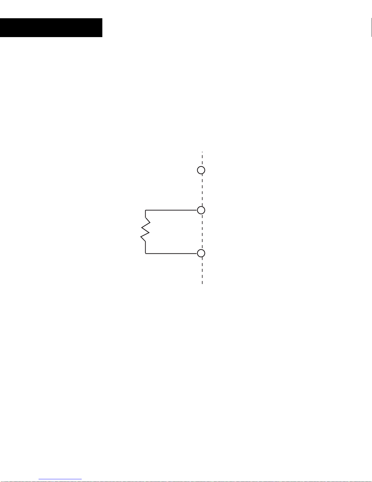
AO-4-8
Voltage Output
The voltage out put is a ground-referenced signal with a range of 0-10VDC. The
maximum output cur r ent is 5mA (2,000 ohms minimum resist anc e) . Ens ur e that the
device being connected is either floating or at the same ground potential as the c ontroller .
Configure the out put point with an Electric al Type of
Connect the devic e ac r os s the following terminals:
Device
≥ 2K
Load
Ω
Resistance
Voltage
OUTx I
OUTx V
GND
.
Note: The load r es istanc e ( of t he exter nal dev ic e) m us t be greater than or equal to 2 K
78
Andover Controls
Technical Manuals Online! - http://www.tech-man.com
.
Ω
Page 85
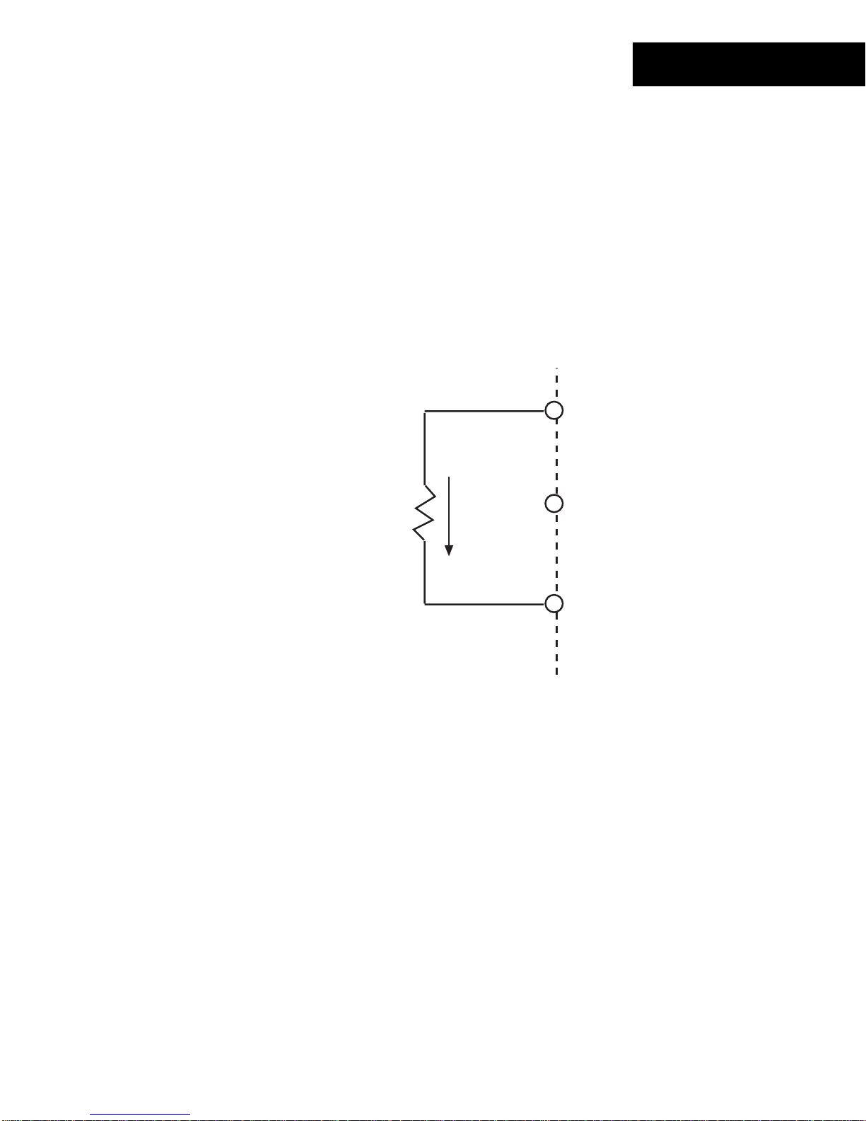
Current Output
The current output is a current-sourcing, ground ref er enc ed c ir c uit. This output can
source 0 - 20 mA with a maximum load impedance of 650 ohm s .
AO-4-8
Configure the out put point with an Electric al Type of
Connect the devic e ac r os s the following terminals:
Device
Load
Resistance
≤ 650
Ω
Current
OUTx I
OUTx V
GND
.
Note: The load r es istanc e ( of t he exter nal dev ic e) m us t be less than or equal to 650
Technical Manuals Online! - http://www.tech-man.com
.
Ω
Continuum I/O System Reference
79
Page 86

AO-4-8
Status/Control P a nel
Status In dic a t or s
The AO-4-8 module includes a c om plete indicator st atus panel on the front of the module.
POWER
COMM
OVERRIDE
STATUS
COMMISSION
RESET
AO-4
This panel includes indicators reporting on the status of the following:
POWER
This green indicat or illum inates when DC power is applied through the
Power/IO Bus .
COMM
This yellow indicat or illum inates when data is tr ans m itt ed from the
module to the Net Controller. In normal operation, data is only transmit ted
when an input value changes.
This indicator will als o flash periodically as t he NetController check s the
I/O bus periodically .
STATUS
This red indicat or is nor m ally off . If it is alway s on or flas hing at a fast
rate there is a problem wit h the module.
This indicator c an be m anually illum inated from the Continuum
workstation and used as a troubleshooting aid when locat ing a particular
module. More inf or m ation on using this indicator may be found in t he
OVERRIDE
Troubleshooting
This red indicat or illum inates whenever any of the over r ide s witches is in
section of this manual.
a position other than AUTO.
80
Andover Controls
Technical Manuals Online! - http://www.tech-man.com
Page 87

This panel also includes two operator swit c hes that perfor m the f ollowing:
AO-4-8
COMMISSION
RESET
After phy s ic al installation and during configurat ion through the
Continuum workstation, pressing this button registers the module’s
address with t he s yst em. For m or e information, refer to the section on
Configuring I/ O
found earlier in this manual.
Should the module become inoper able, pressing this button resets the
module. It does not er as e its m emory.
Technical Manuals Online! - http://www.tech-man.com
Continuum I/O System Reference
81
Page 88

82
Andover Controls
Technical Manuals Online! - http://www.tech-man.com
Page 89
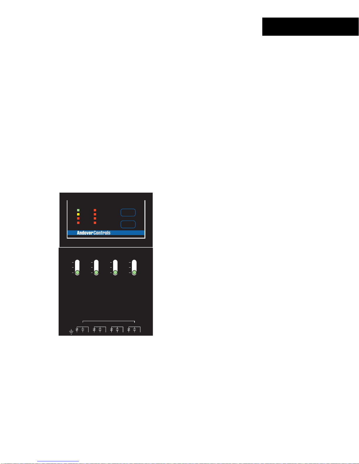
DO-4-R
The DO-4-R, Cont inuum ’s digital output module, has four Form C relay outputs, rated at
5 amps, 240 VAC. These ver s atile out puts make the DO-4-R an excellent c hoic e for
switching mot or star ters and other inductive loads up to 240 VAC, with either two position
(on/off ) or pulse-width modulation (PWM) c ontrol. The PWM feature permits the
modulation of valv es and dam per s to 0.1 second resolution. Two adjac ent Form C relay
outputs can be c om bined in s oft war e to provide a Tri-state out put, for bi- dir ec tional
control of v alv es and dam per s and other end dev ic es . Metal oxide varistors and 5000V
isolation on each output ensure reliable noise-f r ee oper ation.
A DO-4-R-O model with f ull ov er r ide c apabilities is also available. E ac h output has a local
hand-off-auto switch, which enables ser v ic e per s onnel to override the out put. The switch
also provides overr ide feedback of output values for use in troubleshooting or test
conditions. A loc al indic ator light for each output displays relay stat us. A nother LED
provides override s tatus.
FEATURES
POWER
COMM
OVERRIDE
STATUS
OUTPUT
1
2
3
4
COMMISSION
RESET
DO-4
4 Form C Relay Outputs
•
240 VAC @ 5A Contact Rating
•
Output Status LEDs
•
USE COPPER CONDUCTORS ONLY
USE COPPER CONDUCTORS ONLY
OUT1
ON
OFF
AUTO
WARNING:
AVERTISSEMENT:
READER
POWER
CAUTION:
OUT2
ON
OFF
AUTO
HIGH VOLTAGE INSIDE-DANGEROUS TO
UNQUALIFIED PERSONS.
MORE THAN ONE DISCONNECT MAY BE
REQUIRED TO DE-ENERGIZE THIS EQUIPMENT.
+ 5V, 100mA
CONTACT RATING: 240 VAC, 5A
+ 12V, 180mA
30 VDC, 5A
READER
+
G
DC
A
E
N
V
L
T
D
D
OUT1
K
A
/
/
1
0
123456789101112
4
12
56
3
OUT3
1-DOOR
ON
ON
OFF
OFF
AUTO
AUTO
HAUTE TENSION A L'INTERIEUR-DANGER
POUR LES PERSONNES NON-QUALIFIER.
CONTACT RATING:
23
D
O
O
R
7
R
E
X
8
24VAC/DC, 5A
DIGITAL OUTPUTS
1-DOOR
R
E
T
10 11 12
9
SUPERVISED
INPUTS(0-5V)
DIGITAL OUTPUTS
1
L
A
OUT2 OUT3
U
X
ON
ON
OFF
OFF
AUTO
AUTO
OUT4
OUT 2
OUT2
OUT4
13 14 15
DO-4-R-O Only:
Override T oggle S witches
•
Override Det ec tion
•
Technical Manuals Online! - http://www.tech-man.com
Continuum I/O System Reference
83
Page 90

DO-4-R
SPECIFICATIONS
ELECTRICAL
Power Consumption:
2.8 watts at 24VDC max; normally provided by Continuum
power supply module.
Overload Protection:
OUTPUTS
DO-4-R:
DO-4-R-O:
Output Rating:
Output Resolution:
Output Protection:
Output Overrides:
Override Feedback:
0.5A resettable fuse with transient voltage suppressor
(TVS) and reverse polarity protection.
4 Form C relay outputs
4 Form C relay outputs with overrides
240 VAC, 5 amps; 30 VDC, 5 amps
0.1 sec. For Pulse Width Modulation (PWM) control
270 Volt varistors across contacts.
5000 VRMS isolation @ 60 Hz between relay contacts and
relay coil.
3-position manual override switch on each output, with
software feedback.
LED override status indicator (DO-4-R-O only)
Override detection and feedback provided for each output.
Output Connections:
84
Andover Controls
Two-piece, 13-position removable terminal block
Technical Manuals Online! - http://www.tech-man.com
Page 91

DO-4-R
I/O Connections
The actual output connections are locat ed on a thirt een-position removable screw
terminal connector located at the bottom of t he module. Output wires should enter from
either the t op or bottom wiring troughs, and should c om e from the r ight side of the rack
(by convention) .
The outputs ar e labeled OUT 1 NC, OUT 1 NO, OUT 1 COM, and so forth. Each out put
presents a single pole double throw set of contac ts. OUT 1 NC is the normally closed
side of the contact. OUT 1 NO is the normally open contact. OUT 1 COM is the common
connection that represents the arm ature of the relay switch.
The diagram below indicat es wher e eac h output number is located in the terminal block.
Shield/Eart h Ground
1. OUT 1 NC
2. OUT 1 NO
3. OUT 1 COM
4. OUT 2 NC
5. OUT 2 NO
6. OUT 2 COM
7. OUT 3 NC
8. OUT 3 NO
9. OUT 3 COM
10. OUT 4 NC
11. OUT 4 NO
12. OUT 4 COM
OUTPUT
POWER
COMM
OVERRIDE
STATUS
OUT1
ON
OFF
AUTO
WARNING:
AVERTISSEMENT:
READER
POWER
CAUTION:
+ 5V, 100mA
+ 12V, 180mA
READER
+
G
N
V
D
OUT1
123456789101112
12
1
2
3
4
USE COPPER CONDUCTORS ONLY
USE COPPER CONDUCTORS ONLY
OUT2
ON
OFF
AUTO
HIGH VOLTAGE INSIDE-DANGEROUS TO
UNQUALIFIED PERSONS.
MORE THAN ONE DISCONNECT MAY BE
REQUIRED TO DE-ENERGIZE THIS EQUIPMENT.
CONTACT RATING: 240 VAC, 5A
SUPERVISED
30 VDC, 5A
INPUTS(0-5V)
DIGITAL OUTPUTS
1
L
DC
A
E
L
T
A
/
1
3
A
D
OUT2 OUT3
K
U
X
/
0
4
56
OUT3
1-DOOR
ON
ON
OFF
OFF
AUTO
AUTO
HAUTE TENSION A L'INTERIEUR-DANGER
POUR LES PERSONNES NON-QUALIFIER.
CONTACT RATING:
24VAC/DC, 5A
DIGITAL OUTPUTS
23
D
O
O
R
7
1-DOOR
R
R
E
E
T
X
10 11 12
9
8
COMMISSION
RESET
DO-4
OUT4
OUT 2
ON
ON
OFF
OFF
AUTO
AUTO
13 14 15
OUT2
OUT4
Technical Manuals Online! - http://www.tech-man.com
Continuum I/O System Reference
85
Page 92

DO-4-R
Output Circuitry
The following is a sim plified schematic of each DO-4- R Output channel:
OUT x NC
OUT x NO
OUT x COM
All 4 channels resemble the circuit shown above.
These output c ontacts operate as a standard relay. When t he output is set to an ‘ON’
state, the nor m ally open c ontacts (OUTx NO) close and the normally clos ed c ontacts
(OUTx NC) open.
To use the Form C output in your system, configure an output point with an Electrical
Type of
Digital
.
86
Andover Controls
Technical Manuals Online! - http://www.tech-man.com
Page 93

DO-4-R
Override Con t rol s
The DO-4-R-O model includes an output override switch for each output.
ON
OFF
AUTO
The output of t he module can be direc ted from program control t o manual
control. The output can be disabled complet ely as well.
The following describes the act ions associated with each position of the override
controls:
ON
OFF
AUTO
The output r elay is energized to an ‘ON’ state manually by
setting t he s witch to ON. Programs have no effect on the output
when the switch is in this pos ition.
The output r elay is de-energiz ed to an ‘OFF’ state manually by
setting t he s witch to OFF. Programs have no effect on the out put
when the switch is in this pos ition.
The action of the output relay is determined as a direct result of
program contr ol.
Technical Manuals Online! - http://www.tech-man.com
Continuum I/O System Reference
87
Page 94

DO-4-R
Tri-State Output
Although the module c ontains four separate form C relays, adjacent pairs (OUT 1 and
OUT2 or OUT3 and OUT4) of thes e can be combined to form a standard Tri-state out put.
Configure the out put point of the first point (OUT1 or OUT3) with an Electrical Type of
Tri-state
.
Connect the t wo outputs together as follows:
+ ON
Common
OUT 1 NC
OUT 1 NO
OUT 1 COM
OUT 2 NC
OUT 2 NO
OUT 2 COM
88
Andover Controls
OFF
ON
Technical Manuals Online! - http://www.tech-man.com
Page 95

Status/Control P a nel
Status In dic a t or s
The DO-4-R module includes a c om plete indicator st atus panel on the front of the
module.
OUTPUT
POWER
COMM
OVERRIDE
STATUS
1
2
3
4
COMMISSION
RESET
DO-4
DO-4-R
This panel includes indicators reporting on the status of the following:
POWER
This green indicat or illum inates when DC power is applied through the
Power/IO Bus .
COMM
This yellow indicat or illum inates when data is tr ans m itt ed from the
module to the Net Controller. In normal operation, data is only transmit ted
when an input value changes.
This indicator will als o flash periodically as t he NetController check s the
I/O bus periodically .
OVERRIDE
This red indicat or illum inates whenever any of the over r ide s witches is in
a position other than AUTO.
STATUS
This red indicat or is nor m ally off . If it is alway s on or flas hing at a fast
rate there is a problem wit h the module.
This indicator c an be m anually illum inated from the Continuum
workstation and used as a troubleshooting aid when locat ing a particular
module. More inf or m ation on using this indicator may be found in t he
Troubleshooting
section of this manual.
OUTPUT
These red indicat or s ( one for eac h c hannel) illum inate when an ‘ON’
condition is set .
Technical Manuals Online! - http://www.tech-man.com
Continuum I/O System Reference
89
Page 96

DO-4-R
This panel also includes two operator swit c hes that perfor m the f ollowing:
COMMISSION
RESET
After phy s ic al installation and during configurat ion through the
Continuum workstation, pressing this button registers the module’s
address with t he s yst em. For m or e information, refer to the section on
Configuring I/ O
found earlier in this manual.
Should the module become inoper able, pressing this button resets the
module. It does not er as e its m emory.
90
Andover Controls
Technical Manuals Online! - http://www.tech-man.com
Page 97
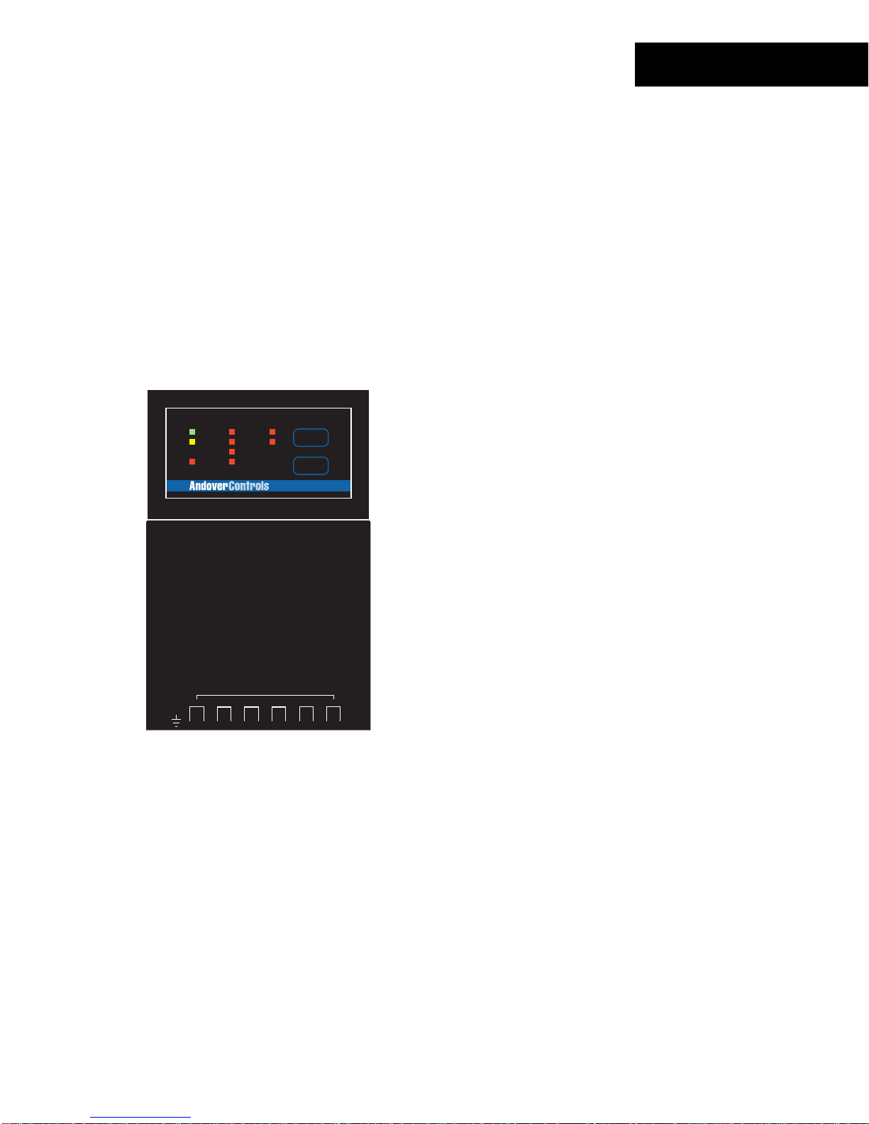
DO-6-TR
The DO-6-TR, Continuum ’s triac output module, has s ix Form A triac - bas ed outputs,
rated at 0. 5 amps, 24 VAC, f or cost-effective on/off or puls e- width modulation (PWM)
control of lighting, heat, and fan unit s. The PWM feat ur e per m its the modulation of valves
and dampers to 0. 1 second res olution. Adjacent outputs can also be configured in pairs
to provide up to three Form K, Tri-state outputs for bi- dir ec tional control of dampers and
valves.
Metal oxide varis tors and optocouplers on the DO-6-TR provide 2500V isolation on eac h
output, ens ur e nois e- free operation, and, in most c as es , eliminate the need to install
MOVs in the field.
FEATURES
OUTPUT
OUTPUT
1
POWER
COMM
STATUS
USE COPPER CONDUCTORS ONLY
USE COPPER CONDUCTORS ONLY
5
2
3
4
COMMISSION
6
RESET
DO-6
1-DOOR
ON
OFF
AUTO
OUT 2
ON
OFF
AUTO
Six (6) Triac-bas ed outputs
•
24 Vrms @ 5A Contact Rating
•
Output Status LEDs
•
READER
POWER
+ 5V, 100mA
OUTPUT RATING: 24 VAC, 0.5A
+ 12V, 180mA
SUPERVISED
DC
A
T
OUT2
A
/
1
3
L
K
/
0
4
INPUTS(0-5V)
DIGITAL OUTPUTS
1
L
E
A
D
OUT3
U
X
56
23
D
O
O
R
7
READER
+
G
N
V
D
OUT1
12345678
12
R
R
OUT4
E
E
T
X
9
8
CONTACT RATING:
DIGITAL OUTPUTS
1-DOOR
OUT5
910
13 14 15
10 11 12
OUT2
OUT6
11 12
Technical Manuals Online! - http://www.tech-man.com
Continuum I/O System Reference
91
Page 98

DO-6-T R
SPECIFICATIONS
ELECTRICAL
Power Consumption:
1.1 watts at 24VDC max; normally provided by Continuum
power supply module.
Overload Protection:
OUTPUTS
Output Type:
Output Rating:
Output Accuracy:
Output Protection:
Output Connections:
0.5A resettable fuse with transient voltage suppressor
(TVS) and reverse polarity protection.
6 Form A optically isolated triac outputs (can be configured
up to 3 Form K Tri-State outputs)
0.5A, 24 VAC, (Cannot switch DC loads)
0.1 sec. for Pulse Width Modulation (PWM) control
2500V optical isolation
Metal oxide varistor and snubber on each output
Two-piece, 13-position removable terminal block
92
Andover Controls
Technical Manuals Online! - http://www.tech-man.com
Page 99
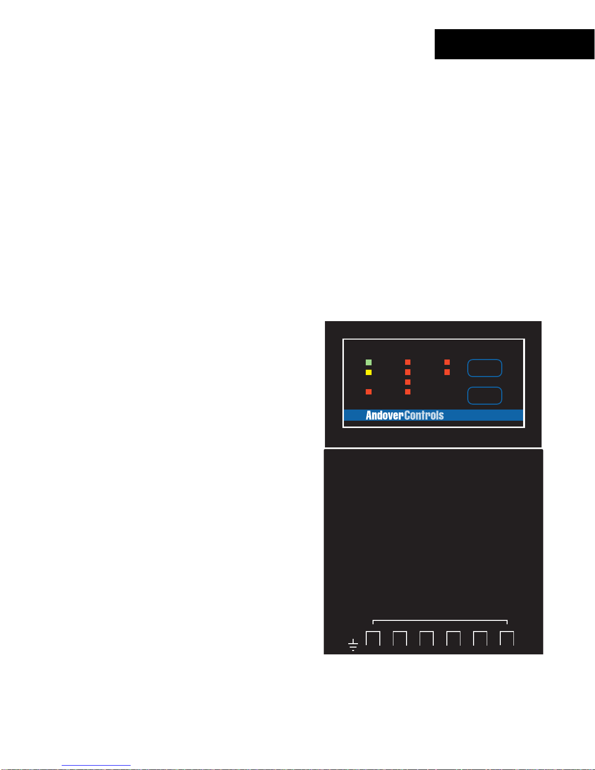
DO-6-TR
I/O Connections
The actual output connections are locat ed on a thirt een-position removable screw
terminal connector located at the bottom of t he module. Output wires should enter from
either the t op or bottom wiring troughs, and should c om e from the r ight side of the rack
(by convention) .
The outputs ar e grouped in pairs of two connector terminals per c hannel. Each output
presents a norm ally open s ingle pole s et of contacts.
The diagram below indicat es wher e eac h output number is located in the terminal block.
Shield/Eart h Ground
1. OUT 1
ON
OFF
AUTO
OUTPUT
5
6
1-DOOR
COMMISSION
RESET
DO-6
OUT 2
ON
OFF
AUTO
2. OUT 1
3. OUT 2
4. OUT 2
5. OUT 3
6. OUT 3
7. OUT 4
8. OUT 4
9. OUT 5
10. OUT 5
11. OUT 6
12. OUT 6
OUTPUT
POWER
COMM
STATUS
1
2
3
4
USE COPPER CONDUCTORS ONLY
USE COPPER CONDUCTORS ONLY
Technical Manuals Online! - http://www.tech-man.com
READER
POWER
+ 5V, 100mA
OUTPUT RATING: 24 VAC, 0.5A
+ 12V, 180mA
READER
+
G
DC
A
N
V
T
D
OUT1
A
/
1
12345678
12
3
L
OUT2
K
/
0
4
SUPERVISED
INPUTS(0-5V)
DIGITAL OUTPUTS
1
23
L
E
D
A
O
D
OUT3
U
O
X
R
56
7
R
R
OUT4
E
E
T
X
9
8
CONTACT RATING:
DIGITAL OUTPUTS
1-DOOR
OUT5
910
10 11 12
13 14 15
OUT2
OUT6
11 12
Continuum I/O System Reference
93
Page 100

DO-6-TR
Output Circuitry
The following is a sim plified schematic of each DO-6- TR Output channel:
OUT x
OUT x
All 6 channels resemble the circuit shown above.
These output c ontacts operate as a solid state relay . W hen the out put is s et t o an ‘ON’
state, the c ontacts close allowing current t o flow between the output terminals .
To use the Form A output in your system, configure an output point with an Electrical
Type of
Digital
.
94
Andover Controls
Technical Manuals Online! - http://www.tech-man.com
 Loading...