

Page 1

ACX 780/781
Installation Guide
Downloaded from - http://www.guardianalarms.net
ACX 780/781 Installation Guide i
Page 2

© 1998, Andover Controls Corporation
All Rights Reserved
No part of this publication may be reproduced, read or stored in a retrieval system, or transmitted, in any form or by any means, electronic, mechanical, photocopying, recording, or
otherwise, without prior written permission of Andover Controls Corporation.
Produced in the United States of America.
Infinity is a trademark of Andover Controls Corporation. All other trademarks are the prop-
erty of their respective owners.
ACX 780/781 Installation & User's Guide, Version: F, February 1998
Andover Controls part number: 30-3001-392
The information in this book is furnished for informational purposes only, is subject to
change without notice, and should n ot be construed as a commitment by Andover Controls
Corporation. Andover Controls Corporation, assumes no liability for any errors or inaccuracies that may appear in this document.
Related Documents
Infinity CX Programmer’s Guide, 30-3001-166
SX 8000 Programmer’s Guide, 30-3001-174
Andover Controls Corporation
300 Brickstone Square
Andover, MA 01810
(978) 470-0555
fax: (978) 470-0946
ii Andover Controls Corporation
Page 3

Preface
The ACX 780/781 Installation Guide presents instructions for installing the ACX
780 and ACX 781 access controllers on an Infinet network. It first presents site prep-
aration information and then step-by-step installation instructions.
ACX 780/781 Installation Guide iii
Page 4

iv Andover Controls Corporation
Page 5

Contents
Setting Up the ACX 780/781 Controller and Infinet
Site/System Setup Requirements....................................................................................................... 2
Controller Dimensions and Weight............................................................................................ 3
Power Re q ui r ements ... .. ... .............. ... .. ...................... .. ... ...................... .. ... ..................... ... .. .. ..... 3
Cable Limitations ....................................................................................................................... 3
Lightning Protection................................................................................................................... 4
Building Ground Requirements ................................................................................................. 4
Inspecting the Ground ................................................................................................................ 5
Environ m e n tal Requ ir e men ts.. .. ............... .. ... ...................... .. ... ............................. .. ... ................ 6
Special Wire for Card Reader Inputs ......................................................................................... 6
Special Wire for Keypad Input s....... ................................. .................... .. .................... .. .......... .. .7
Outpu t R eq u irements..... ... ...................... .. .. ...................... ... .. ...................... .. ... ...................... .. .. 7
Input Requirements .................................................................................................................... 8
Laying Out the Site Setup .......................................................................................................... 9
Instal ling the
Parts Required .......................................................................................................................... 10
Mounting.................................................................................................................................. 10
Connecting the AC Power Cabl e to the Power Supply................. ........................... ................14
Wirin g th e In f i net to the
Wiring the
Wiring Inputs............................................................................................................................ 18
Supervisory Input Circuits ......... ........................... .............................................. ..................... 20
Wiring Door Switches.............................................................................................................. 22
Wiring Motion Sensors/Exit Push Buttons .............................................................................. 24
Wiring the Other Two-Wire Inputs............. .............................. .. .......... .. .................... .. .......... .26
Wiring the Card Reader Inputs................................................................................................. 26
Wiring the Keypad Inputs ...... ................... ................... ........................... .......... ................... ....33
Wiring Outputs ................................................................................................................................ 34
Wiring the Door Outputs.......................................................................................................... 34
Powering Up the
Reset Bu t to n .... .. ... .............. ... .. ...................... .. ... ...................... .. .. ...................... ... .. ....... ... .. ..... 3 9
Connecting Main Batteries.......................................................................................................40
Connecting the Andover Controls Service Tool............... .................. ........... ..........................41
ACX 780/781
Infinet
ACX 780/781
............................................................................................................. 10
ACX 780/781
to the
Infinity CX 9000
....................................................................................................... 37
.................................................................................... 15
or
.................................................................. 16
9200
Appendix —Underwriters Laboratories Requirements
ACX 780/781 Installation Guide v
Page 6

Figures
Figure 1. Dimensions/Location of Mounting Holes and Knockouts in
Cabinet, in inches (mm).......................................................................................11
Figure 2. Inside the ACX 780/781...............................................................................13
Figure 3. Metal Plate and Screw for Power Supply Wire...........................................14
Figure 4. Infinet Cable Wiring....................................................................................15
Figure 5. Attaching the Infinet Cable to Infinity CX 9000 or 9200 ............................16
Figure 6. Normally Closed Supervisory Inputs..........................................................20
Figure 7. Normally Open Supervisory Inputs............................................................. 21
Figure 8. Wiring Ordinary Switch to DoorSwitch Input ............................................22
Figure 9. Wiring Switch with Built-in Resistor to DoorSwitch Input ........................23
Figure 10. Functioning of DoorSwitch Input Wired to
Supervisory Input.................................................................................................24
Figure 11. Functioning of Passive Infrared (PIR) Motion Detector Switch
Wired to Supervisory Input..................................................................................25
Figure 12. Wiring Diagram for Counter or Digital Input...........................................26
Figure 13. Connections Between Card Reader and Controller. ...... .......... .......... ........27
Figure 14. Wiring Wiegand Card Reader (Sensor En gineering) to
Controller........................................................................................................................28
Figure 15. Connections Between Card Reader and Controller. ...... .......... .......... ........29
Figure 16. Wiring Proximity Wiegand Card Reader to Controller,
with 12 VDC Power Supply ................................................................................30
Figure 17. Connections Between Card Reader and Controller. ...... .......... .......... ........31
Figure 18. Wiring Dorado ABA Card Reader to Controller.......................................32
Figure 19. Wiring Diagram for DOOR and AUX Form C Outputs
if Norma ll y O p en .. ...... ........................ ......................... ........................ ................3 5
Figure 20. Wiring Diagram for DOOR and AUX Form C Outputs
if Norma ll y Cl o sed.................. ......................... ........................ ........................ ....3 6
Figure 21. Power Supply Status Display ....................................................................38
Figure 22. Status Lights on Front Door of Cabinet Provided .....................................38
Figure 23. Location of Override and Status Lights ....................................................40
Tables
Table 1. Maximum Length Wire for Card Readers......................................................6
vi Andover Controls Corporation
Page 7

Setting Up the ACX 780/7 81
Controller and Infinet
The ACX 780/781 is a building access controller that can control access
to up to eight doors. For each door, you may control access with either
Wiegand or ABA card readers, which read access cards, or security
keypads, which accept access codes. You may also use both the card
reader and the security keypad together, for extra tight security.
The unit contains a microprocessor running at 2.4576 MHz with 1 MB
of RAM with battery backup, 512 KB of EPROM, and 4 KB of
EEPROM. In addition, it has a service port where you can connect an
LSX 280 laptop service tool.
This manual covers the following:
• Site/System Setup Requirement s
• Installing the ACX 780/781
• Powering Up the ACX 780/781
Warranty Registration
Your warranty is effective for 18 months starting on the date the system
is shipped.
Warning
All wiring and installations must comply with local, state, and national
electrical codes.
ACX 780/781 Installation Guide 1
Page 8

Site/System Setup Requirements
Before you proceed to install the system, you should map out where you
plan to install each controller, terminal/workstati on, and modem. When
planning the sites, be aware of any electrical interference that may occur. You also need to be aware of cabinet dimensions, power
requirements, cable limitations, an d environm ental requir e ments .
Note
This equipment has been tested and found to comply with the limits for
a Class A digital device, pursuant to Part 15 of the FCC Rules. These
limits are designed to provide reasonable protection against harmful
interference when the equipment is operated in a commercial
environment. This equipment generates, uses, and can radiate radio
frequency energy and, if not installed and used in accordance with the
Hardware Instal lation
instructions in this manual, may cause harmful interference to radio
communications. Opera tion of this equipment in a residential area is
likely to cause harmful interference in which case the user will be
required to correct the interference at his own expense.
Note
This digital apparatus does not exceed the Class A limits for radio noise
emissions from digital apparatus set out in the Radio Interference
Regulations of the Canadian Department of Communications.
Avis
Le présent appareil numérique n’émet pas de bruits radioélectriq ues
dépassant les limites applicables aux appareils numériques de la class A
prescrites dans le Règlement sur le brouillage radioélectrique édicté par
le ministère des Communications du Canada.
2 Andover Controls Corporation
Page 9

Hardware Installation
Controller Dimensions and Weight
Each ACX 780/781 is 26 × 19 × 6 in. (660 × 483 × 152 mm) and weighs
40 lbs (18.2 kg).
Power Requirements
Caution
The ACX 780/781 should receive power from its own independent,
unswitched circuit.
The internal power supply allows an AC supply voltage of 115 V to
230 V without requiring any manual switch or jumper setting.
The ACX 780/78 1 consumes 75 VA of power at 115/230 VAC.
Cable Li m i ta tions
The maximum cable length for all buses is 4,000 ft (1200 m) at
19,200 baud (up to 32 Infinet controllers). You can extend buses beyond
4,000 ft. or put more than 32 Infinet controllers on less than 4,000 ft. by
using the InfiLink 200 amplification module. Or you can use the In-
fiLink 210 amplification module to switch to fiber optic cable and form
more complex configurations.
Note
You mu s t use s hie ld ed ca bl es f o r Infinet to ensure compliance with the
Class A FCC limits and to provide reliable communications.
Cables that form Infinet are 24-gauge, single-twisted-pair, tinned,
shielded copper wire. Use the following cables1 or their equivalents:
• Brand Rex # H 9002 (single-pair)
• Anixter # 9J2401021 (single-pair plenum cable)
1. You can also use any cables you may already have in place for ACNET or LBUS.
ACX 780/781 Installation Guide 3
Page 10

The cable should have a nominal impedance of 100 Ohms and a nominal velocity of propagation of 78%.
Capacitance of Infinet cable should be nominal, below 12.5 pF/ft
(41pF/m) between conductors and below 22 pF/ft (72 pF/ m) between
the conductor connected to ground and the next conductor.
Lightning Protection
Lightning Arrestors are required at each point where an Infinet or other
wiring (such as for a card reader) enters or exits a building. Use the
following arrestor: Two pair combination gas tube/silicon avalanche arrestor, Andover Controls # 01-210 0-299.
Building Ground Requirements
Hardware Instal lation
Warning
Be sure that all Infi nity products from Ando ver Controls Corporation
are grounded to true earth ground. This kind of ground protects the
equipment from transients and other power surges in the area.
We cannot guarantee that the controller system will operate as
documented unless you properly grou nd all control lers .
Warning
Grounding should be in accordance with article 240 of the National
Electrical Code. Be sure to have your grounds inspected before you
begin the installation proc ess to be sure your municipality follows the
National Electrical Code. Many municipalities do not a nd often have
substandard electrical grounds.
An example of a substandard ground is a galvanized steel cold water
pipe. As the pipe corrodes, it does not act as a true ground. The corrosion acts as an insulator, raising the potential of the pipe with respect to
the ground.
4 Andover Controls Corporation
Page 11

Hardware Installation
When lightning strikes in the area of the ins talla tion, it drastically
changes the potential of the earth. Since properly grounded Andover
Controls units respond to changes in potential more rapidly than poorly
grounded electrical systems, a poorly grounded buildi ng tries to reach
ground through the Andover Controls system. The surge of current can
destroy electronic components on the controller board.
Surges of much lower potential than lightning also impact the reliability
of Andover Controls equipment.
Inspecting the Ground
You can check your ground as follows:
1. Check yo ur ground by firs t inspecti ng the buildi ng power distributi on
panel for ea rth ground ter mination. If the ground t ermination is any of
the following, it is not adequate and must be corrected:
• Does not exist.
• Is connected to a corroded or galvanized pipe.
• Is connected using a small gauge wire thinner than 14 AWG (16
or 18AWG, for example, or less than 2.5 mm2).
2. Be sure your Andover Controls cabinet is connected to the ground
with a copper conductor that terminates at the distribution panel.
Environmental Requirements
The ACX 780/781 operates in rooms with temperatures ranging from 32
to 120°F (0° to 49°C) and with humidity between 10 and 95%,
noncondensing.
Special Wire for Card Reader Inputs
We recommend fi ve- conductor, 22- gauge ( 0. 35 mm2) shielded wire for
wiring card reader inputs.
Table 1 shows the various card brands and the maximum length for #18
gauge wire (1.0 mm2), then for #22 gauge wire (0.35 mm2).
ACX 780/781 Installation Guide 5
Page 12

Hardware Instal lation
Table 1. Maximu m Length Wire for Card Readers
#18 Gauge
#22 Gauge
Card Reader Type
Sensor Engineering
(1.0 mm2)
*
500 ft (152 m) 200 ft (60 m)
(0.35 mm2)
Proximity (12V at ACX 780) 250 ft (76 m) 100 ft (30 m)
Proximity (12V at Reader) 500 ft (152 m) 350 ft (106 m)
Dorado ABA Card Reader 500 ft (152 m) 200 ft (76 m)
*Model number 30387 for UL listed systems.
6 Andover Controls Corporation
Page 13

Hardware Installation
Special Wiring for Keypad Inputs
We recommend eight-conductor, 18-gauge shielded wire for wiring keypad inputs except for the Essex unit, which requires two extra wires
bringing its total to ten conductors.
8-conductor, shielded
10-conductor, shielded for E ssex Touch Pads
You can extend the length of this cable up to 500 ft.
Output Requirements
Each ACX 780/781 has the following outputs:
• Eight door outputs that control a door through card reader or keypad
access. Each output is a Form C door latch relay rated at 120 VAC/
30 VDC, 5 A maximum. You wire these outputs just as you would a
digital/pulsed output.
Resolution of the output is 0.1 sec. You may choose to manually
override the output by setting the OVERRIDE switch to ON or OFF.
Or you can set it to AUTO to have the card reader or keypad and
control system control access through the door.
The OVERRIDE LED indicates at least one of the door outputs is on
manual control; the DOOR OPEN LED indicates the door is open.
• One auxiliary output, also a Form C relay rated at 120 VAC/30 VDC,
5 A maximum. You may want to use this output for a bell or other
audio alarm indicator.
• Eight card reader LED outputs, each rated at 4.3 V or 9 mA.
ACX 780/781 Installation Guide 7
Page 14

Input Requirements
Caution
Andover Controls inputs are designed to be used with the specified card
readers, two-wire door switches, two-wire motion sensors, and other
two-wire input devices; they do not provide sufficient power to operate
sensors requiring an external power supply of 12 or 24 VAC/DC .
Each ACX 780/781 controll er has the foll owing inputs:
• Eight card reader inputs that receive either the Wiegand format or the
standard ABA format. You set the fo rma t late r , in the softwa re.
(UL listed systems must use model 30387 Sensor Engineering card
readers.)
Hardware Instal lation
Maximum data rate for e ach car d r eader—1 ms between bits wi th a
50 µs bit width. Maximum number of bits per card is 256.
Maximum power available to each card reader is 35 mA at 5 VDC.
If the card reader requires 12 or 24 VCD, it requires an
2± 2±
external power supply.
• Eight keypad inputs. You can place keypads near the door as an
alternative to a card reader. The person punches in an access code that
the controller recognizes before allowing the person access. Each
keypad has up to 12 keys and eight wires.
• Thirty-two supervisory inputs (1 through 32) that you can use for any
of the following types of inputs:
— Door switch that indicates the status of the door—open or closed.
Must have a 10 KΩ res istor in ser ies if normall y closed or in
parallel if normally open. The resistor allows the input to detect
tampering. Refer to the Infinity CX Programmer’s Guide for
details. Required.
8 Andover Controls Corporation
Page 15

Hardware Installation
— An exit re quest input, usually a moti on s ensor th a t de termines
someone is a pproaching the door or a push button tha t you must
press to leave the area. Must have a 10 KΩ resistor in series if normally closed or in parallel if normally open. The resistor allows the
input to detect tampering. Refer to the Infinity CX Pr ogrammer’s
Guide for details. Option a l.
Each supervisory input reads the input voltage level and provides
switch position and tampering informat ion.
Each supervisory input can have up to 200 ft of #22 AWG (up to
60 m of 0.35 mm
• Two built-in tamper switches. The first switch reacts when someone
opens the cabinet door. The second switch reacts when the cabinet
has been removed from the wall. When the switch is open, the
2
) 100% shielded wire.
cabinet tamper alarm is ON.
Laying Out the Si te Setu p
You may want to draw a map of where you plan to put each controller
and store it in a notebook.
Find the tag attached to each controller that gives the number of the controller. Bef ore you remove any tags, be sure the tag has all of the
following information on it:
• Location of the controller.
• Serial number.
• Model name and number.
• Communications port the Infinet connects to on the ACX 780/781
controller.
Then collect the tags. You will need to know where your controllers are
located when you later assign a name to each controller and each input
and output.
ACX 780/781 Installation Guide 9
Page 16

Installing the ACX 780/781
Parts Required
To install a single controller you start with the following parts:
• ACX 780 or ACX 781 Controller
• AC Power Cable
• Input and Output Wires
• Up to Eight Card Readers and/or Eight Keypads
• Up to Eight Door Switches
• Up to 32 Motion Sensors, Exit Butto ns, or Other Security Sensors
Hardware Instal lation
• Two Cabinet Tamper Switches
• Infinet Cable (twisted pair)
• InfiLink 200s as Hubs, Repeaters, or Cable Switching Boxes as
required
Mounting
Caution
You must keep the ACX 780/781 in the UL listed enclosure provided.
1. Before you begin, open the front door of the ACX 780 cabinet.
Figure 1 shows the dimensions (in inches) of the UL listed cabinet
that Andover Controls provides and the location of the mounting
screw holes.
10 Andover Controls Corporation
Page 17
Hardware Installation
)
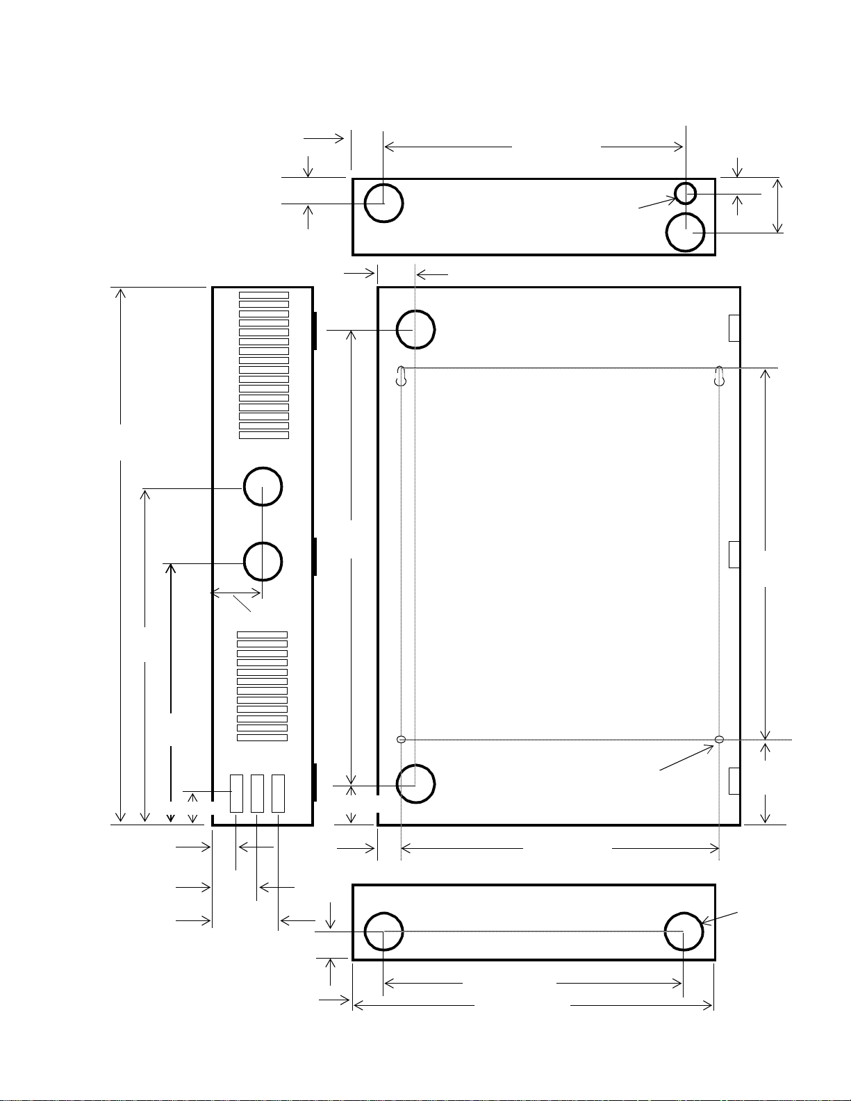
Figure 1. Dimensions/Location of Mounting Holes and Knockouts in Cabinet, in
inches (mm)
26.50
(673)
1.37 (34)
1.39 (35)
×
×
22.85
(580)
16.25 (412)
.75 (19)
×
1.57 (39)
.83 (21) diameter
for a 1/2 NPT
×
×
2.65
(67)
×
19.42
(493)
16.68
(42)
13.23
(336)
.64 (16)
2.30 (58)
2.40 (61)
2.25 (57)
1.52
(39)
1.37 (35)
1.82 (46)
1.00 (25)
1.39 (34)
×
Mounting Holes for
1/4 inch (~6 mm) dia. screws
17.00 (432)
× ×
16.25 (413)
19.00 (483
3.50
(89)
1.65 Dia
(412)
Knockout
9 Places
for a
1 1/4 NPT
ACX 780/781 Installation Guide 11
Page 18

Hardware Instal lation
Caution
Never drill holes in the ACX 780/781 cover or boards. A metal shaving
could easily short circuit the electronics.
2. Position two standard No. 8 screws for the precut eyelets in the
cabinet or backplate, and hang the cabinet or backplate on the
screws.
Figure 2 shows the loca tion of v ariou s pa rts i nsid e the ACX 780/ 78 1,
labeled on the cover plate. Note the parts of the controller labeled here.
You may wa n t to refer to this figure to locate pa rts during th e
installation process.
12 Andover Controls Corporation
Page 19

INFINET
+
—
SHLD
SERVICE
TD
RD
SCAN
ERROR
NO SRV
CPU
+5V
+24V
+15V
-15V
-5V
AC PWR
RESET
PORT
RET
RET
IN9
IN1
IN10
IN2
RET
RET
IN11
IN3
IN12
IN4
RET
RET
IN13
IN5
IN14
IN6
RET
RET
IN15
IN7
IN16
IN8
RET
RET
RET
RET
IN25
IN17
IN26
IN18
RET
RET
IN27
IN19
IN28
IN20
RET
RET
ACX 780/781 Installation Guide 13
IN21
IN22
RET
IN23
IN24
RET
IN29
IN30
RET
IN31
IN32
RET
SUPERVISORY
INPUTS
WARNING
HIGH VOLTAGE PRESENT DISCONNECT
POWER PRIOR TO SERVICING
FOR DETAILED INSTALLATION INSTRUCTIONS,
REVIEW DOCUMENT, 30-3001-392, DATED 1993
ACX78X
ON
OFF
AUTO
ON
OFF
AUTO
ON
OFF
AUTO
ON
OFF
AUTO
ON
OFF
AUTO
ON
OFF
AUTO
ON
OFF
AUTO
ON
OFF
AUTO
ON
OFF
AUTO
OVERRIDE
OUTPUT 1
OUTPUT 2
OUTPUT 3
OUTPUT 4
OUTPUT 5
OUTPUT 6
OUTPUT 7
OUTPUT 8
OUTPUT 9
OUTPUTS
NC
1
C
NO
NC
2
C
NO
NC
3
C
NO
NC
4
C
NO
NC
5
C
NO
NC
6
C
NO
NC
7
C
NO
NC
8
C
NO
NC
9
C
NO
Figure 2. Inside the ACX 780/781
Hardware Installation
D
I
S
P
L
A
Y
TAMPER
SWITCH
READER 1 — KEYPAD 1
1
/
0
D
/
+
L
A
C
5
V
G
E
T
L
NDRIR2R3R4C1C2C
D
A
K
READER 2 — KEYPAD 2
READER 3 — KEYPAD 3
1
/
0
D
/
+
R
L
A
C
E
5
3
T
V
G
E
T
L
NDRIR2R3R4C1C2C
D
A
K
R
E
3
T
READER 4 — KEYPAD 4
READER 5 — KEYPAD 5
1
/
0
D
/
+
L
A
C
5
V
G
E
T
L
NDRIR2R3R4C1C2C
D
A
K
READER 6 — KEYPAD 6
READER 7 — KEYPAD 7
1
/
0
D
/
+
R
L
A
C
E
5
3
T
V
G
E
T
L
NDRIR2R3R4C1C2C
D
A
K
R
E
3
T
READER 8 — KEYPAD 8
Page 20
Connecting the AC Power Cable to the Power Supply
Warning
Be sure the controller is not receiving AC power while you are wiring
it, or you could receive an electrical shock that is life-threatening.
The AC power connection is in the upper right corner of the controller.
You must wire the AC cable to the three scre ws on the far right.
Caution
Be sure to connect all three wires, HOT, NEUTRAL, and GROUND.
Otherwise, the controller could malfunction.
Hardware Instal lation
The three screws are labeled HOT NEU GND.
1. Place the hot wire under the metal plate behind the screw labeled
HOT.
2. Tighten the screw with a flathead screw driver.
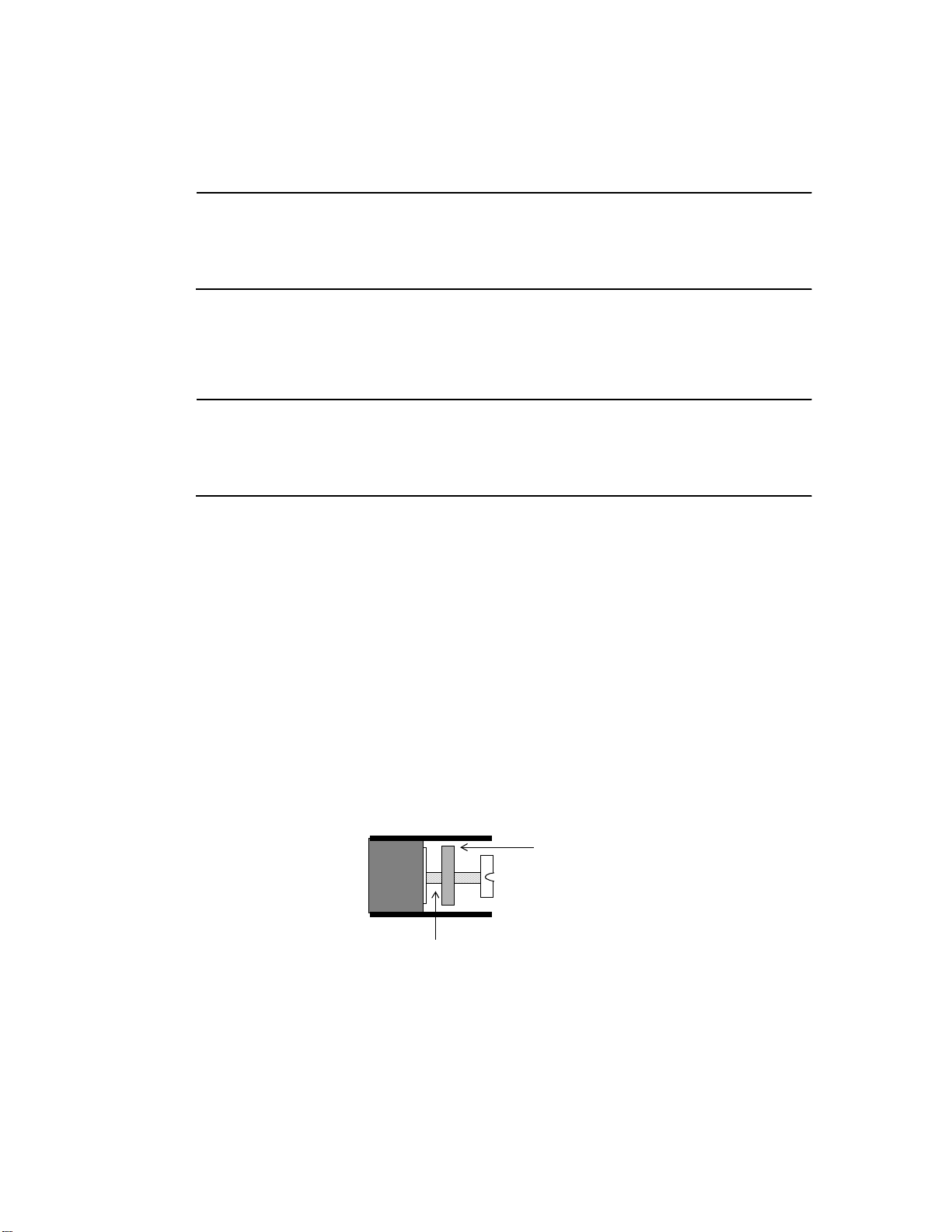
Figure 3 shows the position of the plate, where to place the wire, and
how the screw fits on the plate. You can see how the screw holds the
plate in place once you tighten it.
Figure 3. Metal Plate and Screw for Power Supply Wire
Metal Plate
Insert Wire Here
3. Place the neutral wire under the metal plate behind the screw labeled
NEU.
14 Andover Controls Corporation
Page 21
Hardware Installation
4. Tighten the screw with a flathead screw driver.
5. Place the ground wire under the metal plate behind the screw labeled
GND.
6. Tighten the screw with a flathead screw driver.
Wiring the Infinet to the ACX 780/781
Note
You mu s t use s hie ld ed ca bl es f o r Infinet to ensure compliance with the
Class A FCC limits and to ensure reliable communications.
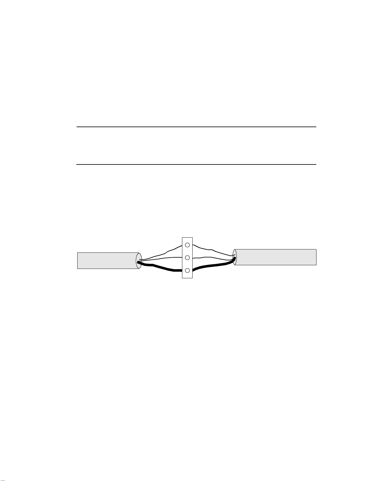
Figure 4 illustrates how to w ire the Infinet cable to the remov a ble
terminal block connector in the upper left corner of the ACX 780/781.
Figure 4. Infinet Cable Wiring
Infinet Connection
+
–
SHLD
1. Trim back the shield over the wires.
2. Take the first wire for the incoming Infinet and the first wire for the
outgoing Infinet and slip both in the hole beneath the screw labeled
with a plus sign.
3. Tighten the screw down on them until the scr ew holds the wir es in
place.
4. Slip the second wire from each Infinet cable under the screw labeled
with a minus sign and tighten the screw down on them.
5. Slip the shields from the incoming and outgoing Infinet cables under
the screw labeled SHLD and tighten the screw down on them.
ACX 780/781 Installation Guide 15
Page 22

Wiring the Infinet to the Infinity CX 9000 or 9200
You connect the last piece of Infinet cabling to the Infinity CX 9000 or
9200, as described below (refer to the illustration):
1. Open the front of the Infinity CX 9000 controller cabinet.
Notice that to the left are three ports labeled COMM1, COMM2, and
COMM3. Two RS-485 ports, one above the three comm ports and
one below, are in the same area.
Notice that the end of the Infinet cable has two wires and a shield.
You wire them to the terminal block connector on the RS-485 port.
Figure 5 illustrates how to w ire the Infinet cable to the Infinity C X
9000 or 9200.
Hardware Instal lation
Figure 5. Attaching the Infinet Cable to Infinity CX 9000 or 9200
2. Run the cable through the knockout on the left side of the controller.
3. Select the port to wire the cable to—on a 9000, either the RS-485
port just above the three RS-232 ports (COMM2) or the RS-485 port
just below the three RS-232 ports (COMM1). Once you use either of
these ports for COMM1 or COMM2, the RS-232 port for COMM1
or COMM2 is disabled. On a 9200, you can also select COMM4.
+IN
–IN
SHLD
+OUT
–OUT
4. Trim back the shield over the wires.
16 Andover Controls Corporation
Page 23

Hardware Installation
5. Slip the first wire through the hole under the screw labeled +IN and
jumper it to the screw labeled +OUT.
6. Tighten both screws to hold the wire there.
7. Slip the ground wire through the hole under the screw labeled
–IN and jumper it to the screw labeled –OUT.
8. Tighten both screws to hold the wire there.
9. Slip the shield in under the screw labeled SHLD and tighten the
screw to hold it there.
ACX 780/781 Installation Guide 17
Page 24

Wiring Inputs
Caution
Do not remotely ground any part of the sensor wiring. Remote grounds
connected to the ACX 780/781 return terminal could make the controller
operate incorrectly or damage the equipment. The signal return is not true
earth ground. It is a n electronic refer ence point necessary to interpret the
sensor properly. Do not externally ground sensor or switch terminals that
return to the ACX 780/ 781.
Caution
Card readers requ i re sh i e l ded wiring .
Although two-wire inputs us ually funct ion properly with unshielded
Hardware Instal lation
sensor wire, you may need shielded wire if you run the wire as follows:
• In the same conduit with other noise-generating conductors such as
50/60 Hz AC power.
• In long runs close to large power-consuming or power-generating
equipment that can produce 50/60 Hz noise.
We recommend you run input wiring in a conduit separate from AC
power or output wiring and avoid long wiring runs.
The “supervisory” in puts are on the left side of the A CX 780/781. Input
wires should enter from the left side. Notice that the inputs are labeled
RET, IN1, IN2, RET, IN3, IN4, RET, IN5, IN6, and so on, for up to 32
inputs. The first return terminal goes to the first two inputs, the second
to the next two inputs, and so on.
18 Andover Controls Corporation
Page 25

Hardware Installation
Caution
Follow the rules below when wiring inputs and outputs:
• Never lay wires across the surface of the printed circuit board. You should
bring input wires in from the left and output wires in from the bottom.
• High voltage AC Power wiring should be routed to the conduit
opening nearest the AC power terminals.
• Do not bundle or route AC Power wiring with low voltage input or
output wiring.
• Bundle excess wires toward the back of the cabinet to avoid any
contact with circuit boards.
• Wires should never be within 1 in. (25 mm) of any component on the
printed circuit board.
• Keep cabinet free of foreign materials (extra power supplies, relays,
and so on).
• Be careful when stripping wire not to drop small pieces of wire
inside the cabinet.
If you violate any of these rules, the controller could malfunction.
ACX 780/781 Installation Guide 19
Page 26
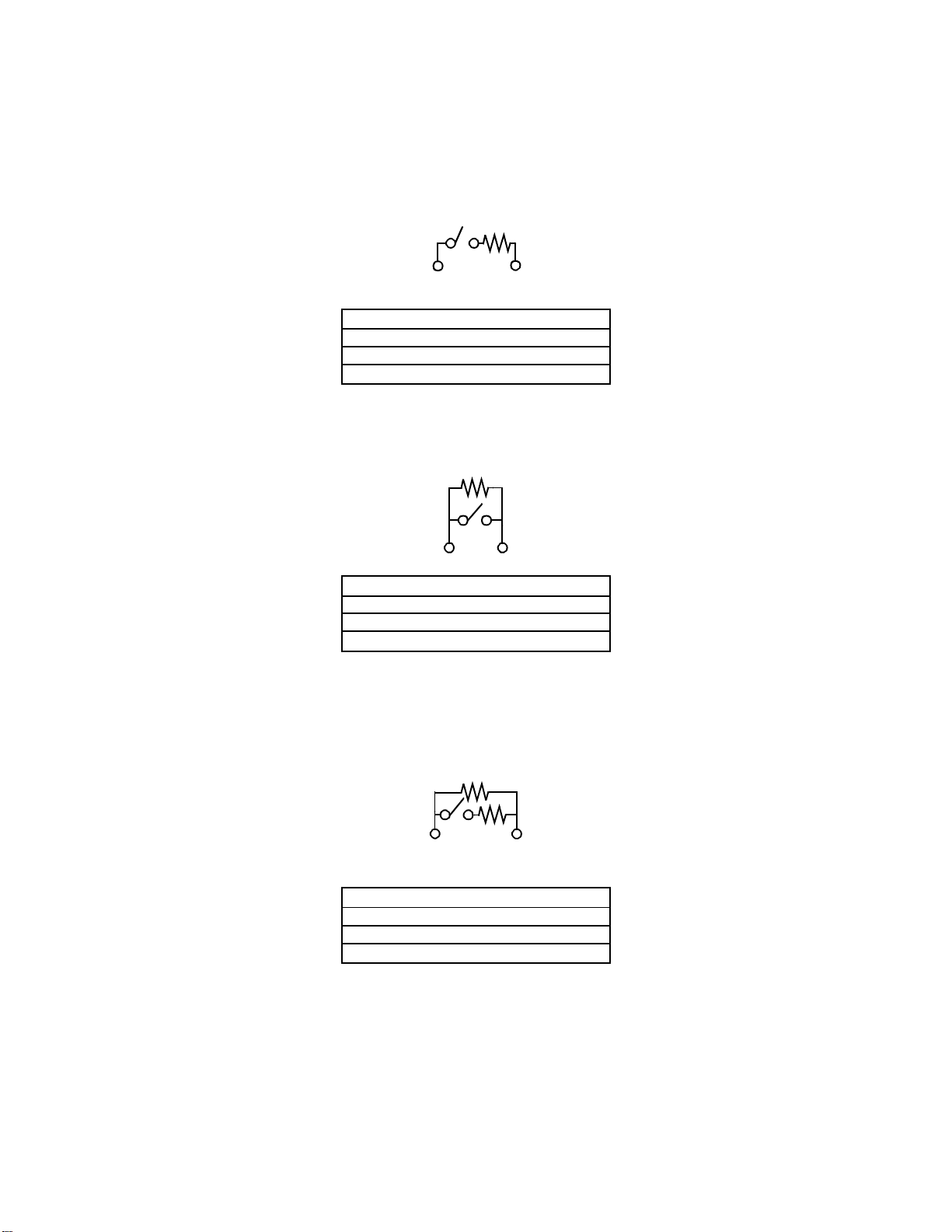
Supervisory Input Circuits
y
All 780/781 controller series inputs are supervisory inputs. The follow-
ing drawings depict the six types of supervisory inputs that exist—three
normally closed and three normally open types. After the drawings,
there is an explanation of which types are recommended for access control installations.
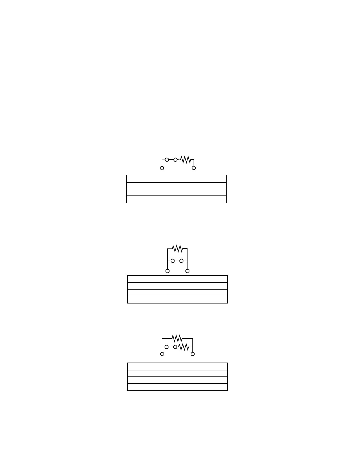
Figure 6 shows the three types of normally closed supervisory inputs.
Figure 6. Normally Closed Supervisory Inputs
NC Series
Door Closed SW Closed 10K
Door Open SW Open Infinite
Hardware Instal lation
SW Shorted Zero K
Wire Cut Infinite
Door Open and Wire Cut conditions both result in an infinite reading
If the door was sensed open without a valid card swipe, a Door Violation
should be triggered.
.
NC Parallel
Door Closed SW Closed Zero K
Door Open SW Open 10K
SW Shorted Zero K
Wire Cut Infinite
Not the best choice, the switch could be shorted and the door forced open,
and the system would still think the door was closed.
NC Series and Parallel
Door Closed SW Closed 5K
Door Open SW Open 10K
SW Shorted Zero K
Wire Cut Infinite
This configuration is the best choice; the parallel and series resistors
provide a redundant securit
20 Andover Controls Corporation
feature.
Page 27
Hardware Installation
Figure 7 shows the three types of normally open supervisory inputs.
Figure 7. Normally Open Supervisory Inputs
NO Series
Door Closed SW Open Infinite
Door Open SW Closed 10K
SW Shorted Zero K
Wire Cut Infinite
This configuration is not the best choice. If the wire is cut and
forced open,
and the system senses that the door is still closed.
the door
NO Parallel
Door Closed SW Open 10K
Door Open SW Closed Zero K
SW Shorted Zero K
Wire Cut Infinite
This configura ti o n is defea ted by shorti n g the switch . The systems senses this
condition as a normal door open situation. However if the wire is cut, that is a
unique resistance that can easily be identified as a tampering situation.
NO Series and Parallel
Door Closed SW Open 10K
Door Open SW Closed 5K
SW Shorted Zero K
Wire Cut Infinite
This configuration provides the most security. There are four unique resistance values
associated with the four possible conditions.
We recommend NO Parallel and NO Series and Pa ralle l types for
access control instal lations. The next sections explain how to wire these
types of inputs for door switches and motion detectors.
ACX 780/781 Installation Guide 21
Page 28

Wiring Door Switches
You may wire up to eight of the 32 supervisory inputs to door switches.
The maximum length wire you may use is 500 ft of #18 gauge wire (152
2
m of 1.0 mm
wire). You wire the door switch as follows (switches may be either normally open or normally closed):
1. Slip the appropriate wire under the IN screw and tighten the screw
down on it.
Figure 8 shows the wiring diagram for the input if the door switch is
an ordinary switch. This switch can detect either the switch position,
or tampering if the switch has an open fault. If the switch is shorted,
it appears closed.
wire) or 200 ft of #22 gauge wire (60 m of 0.35 mm2
Hardware Instal lation
Figure 8. Wiring Ordinary Switch to DoorSwitch Input
RET
Ω
10 K
IN1
Figure 9 shows the wiring diagram for the input if the door switch
has a built-in series resistor. This switch can detect either the switch
position, or tampering where the switch is shorted or grounded. We
recommend this switch for situations requiring the greatest security.
22 Andover Controls Corporation
Page 29
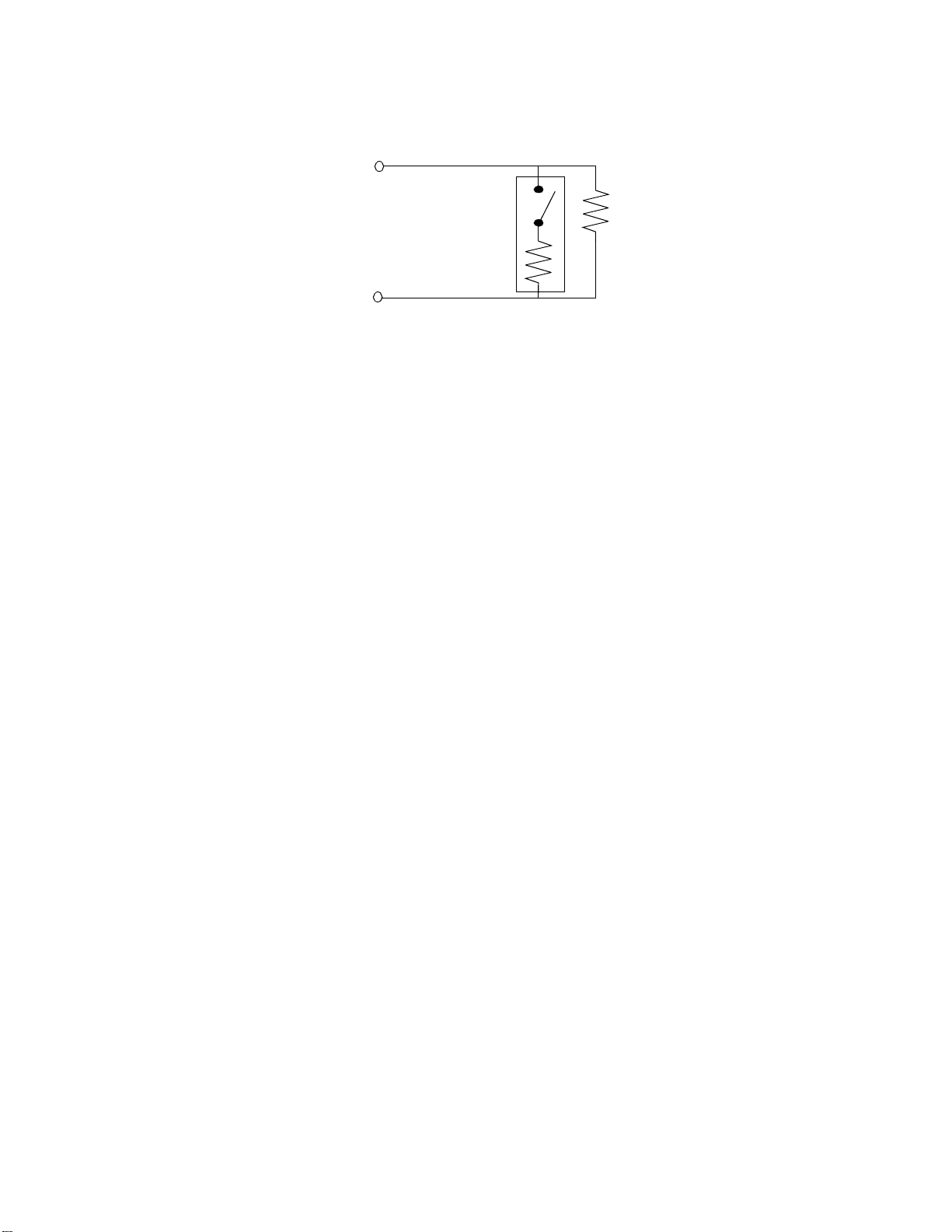
Hardware Installation
Figure 9. Wiring Switch with Built-in Resistor to DoorSwitch Input
Each switch requires a single parallel resistor to provide extra
security should an intruder attempt to break in through the door by
closing the contact.
2. Slip the ground wire under the RET screw that corresponds to the IN
number and tighten the screw down on it.
RET
IN1
10 K
Ω
3. Be sure you wire the 10 KΩ resistor in parallel as shown in each
diagram.
Figure 10 shows the how the door switch works if it is an ordinary
switch (normally open). The switch remains open while the door is in a
normal state (clo sed or not tampered with). If th e switch de te cts the
door is open or has been tampered with, it appears closed.
ACX 780/781 Installation Guide 23
Page 30
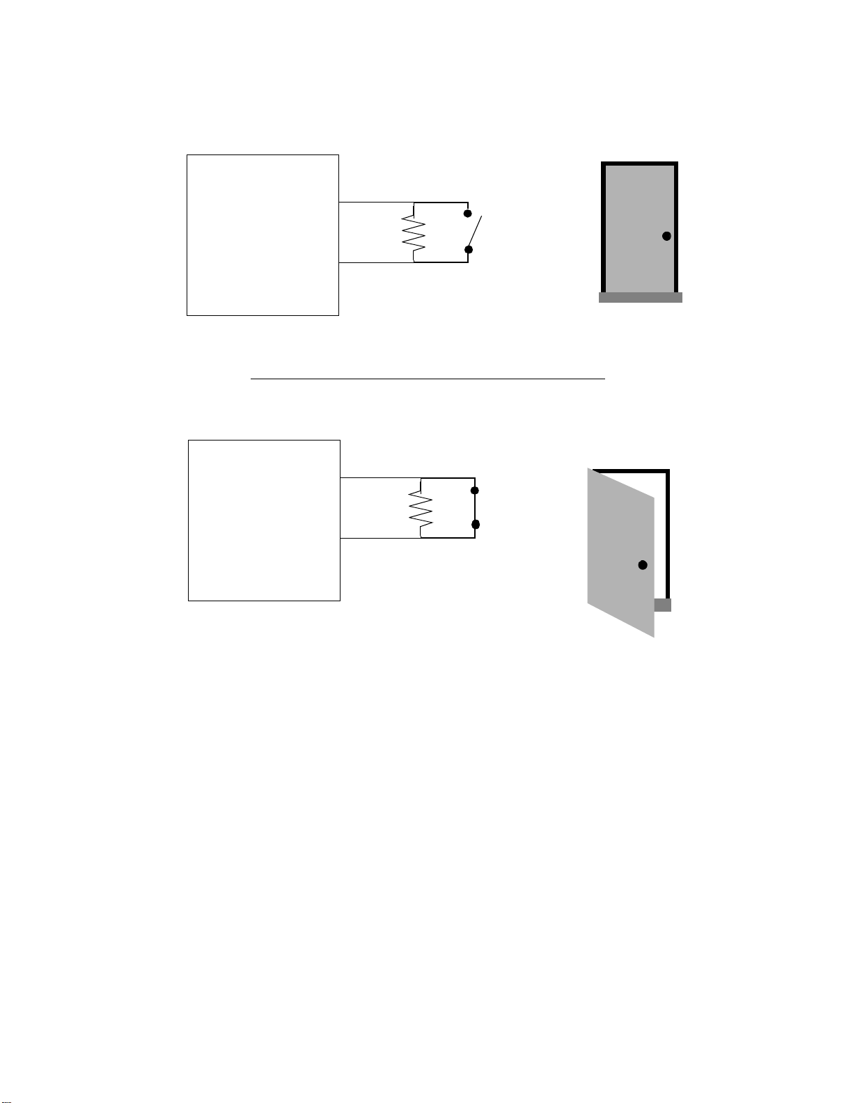
Hardware Instal lation
Figure 10. Functioning of DoorSwitch Input Wired to Supervisory Input
Normally Open DoorSwitch
Access
Controller
Ω
10 K
Door Closed
(Normal)
Normally Open DoorSwitch
Access
Controller
Ω
10 K
Detects
Door Open
Wiring Motion Sensors/Exit Push Buttons
You may wire up to eight of the 32 supervisory inputs to motion sensors
or exit buttons. You wire them the same way you wire DoorSwitch inputs, only the motion sensor requires an external power supply of 12
VDC or 24 VDC (UL listed under APHV). The maximum length
wire you may use is 500 ft of #18 gauge wire (152 m of 1.0 mm
or 200 ft of #22 gauge wire (60 m of 0.35 mm
2±
2
wire).
2
wire)
2±
24 Andover Controls Corporation
Page 31
Hardware Installation
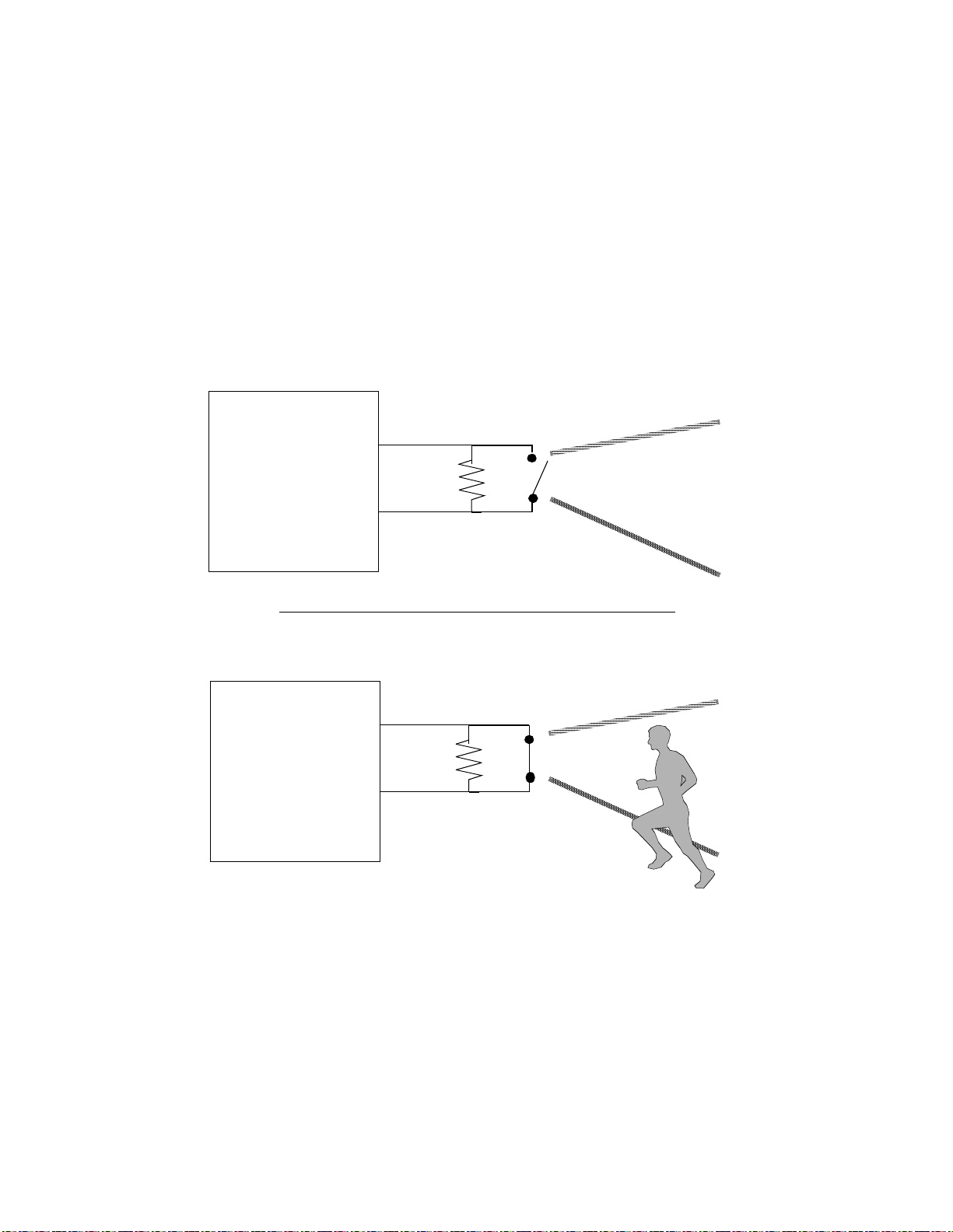
Be sure that when you wire the motion detector, it is correctly set up, as
illustrated in the next figure.
Figure 11 shows the how the motion detector works if it is an ordinary
Passive Infrar ed (PIR) Motion Detector. The switch (norma ll y o pen )
remains open while it detects no motion or tampering If the switch
detects motion, it appears closed.
Figure 11. Functioning of Passive Infrared (PIR) Motion Detector Switch
Wired to Supervisory Input
Access
Controller
Normally Open PIR Motion Detector
No Motion
Detected
Access
Controller
Ω
10 K
Normally Open PIR Motion Detector
Ω
10 K
Motion
Detected!!!
ACX 780/781 Installation Guide 25
Page 32

Wiring the Other Two-Wire Inputs
Follow these steps to wire two-wir e inputs :
1. Slip the first wire for the sensor under the screw labeled IN9 and
tighten the screw down on it.
2. Slip the ground wire under the RET9 screw and tighten the screw
down on them.
3. Repeat the steps for each pair of inputs.
Figure 12 shows a counter wired to an input point.
Figure 12. Wiring Diagram for Counter or Digital Input
Hardware Instal lation
1 (input point 1)
Wiring the Card Reader Inputs
Be sure you wire all card readers with shielded wiring.
The maximum length of wire you may use depends on the card reader
brand name and the type of wiring/cable you use. Refer to the earlier
sections in this manual.
In the case of Proximity card readers, you may connect the required
12 VDC power supply at the ACX 780/781 or at the card reader.
2±
RET (return)
26 Andover Controls Corporation
Page 33

Hardware Installation
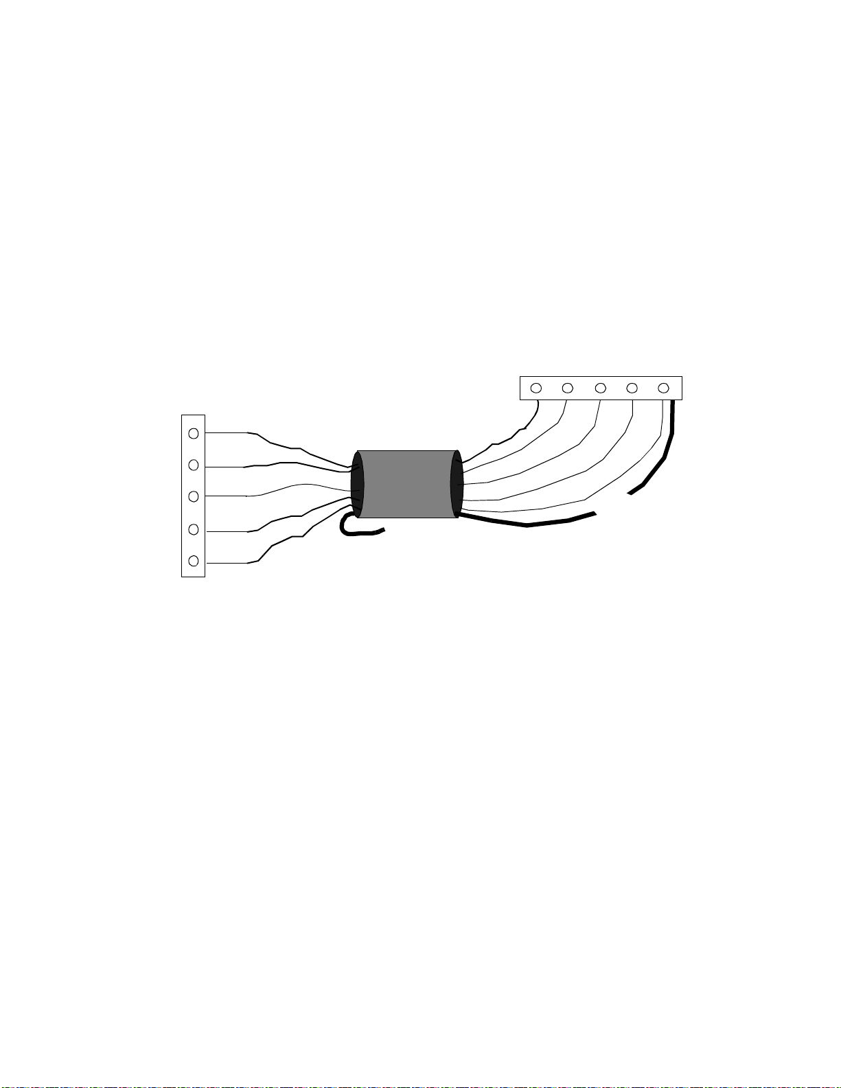
Wiring Wiegand Card Reader (Sensor Engineering)
Wire the Sensor Engineering Wiegand card reader to the READER 1
and READER 2 inputs on the lower left side of the ACX 780/781 as
follows:
1. Look at the wire connection on your Wiegand card reader. Notice
that you have five connection points:
•+ 5VDC
• DATA1
• DATA0
•LED
• GND
2. Wire the first end of each wire to the appropriate connection point
on the card reader.
Figure 13 shows where to connect the various wires on the card
reader and the ACX 780/781.
Figure 13. Connections Between Card Reader and Controller
Card Reader
+5VDC
DATA1
DATA0
LED
GND
ACX 780/781
+5V
LED
1/DATA
0/CLK
GND
Controller
3. Slip the other end of the +5VDC wire under the +5 V screw on the
controller and tighten the screw down on it.
4. Slip the other end of the DATA1 wire under the 1/DATA screw on
the controller and tighten the screw down on it.
5. Slip the other end of the DATA0 wire under the 0/CLK screw on the
controller and tighten the screw down on it.
ACX 780/781 Installation Guide 27
Page 34
Hardware Instal lation
6. Slip the other end of the brown wire under the LED screw and
tighten the screw down on it.
Figure 14 illustrates where you connect the various wires.
Figure 14. Wiring Wiegand Card Reader (Sensor Engineering) to Controller
ACX 780/781
1
/
O
D
/
+
L
A
C
G
5
E
T
L
N
V
D
A
K
Card Reader
+5VDC
D
DATA1
DATA0
LED
GND
Shield
7. Slip the GND wire and the shield under the GND screw and tighten
the screw down on it.
8. Tie back the shield at the card reader end and any wires you do not use.
28 Andover Controls Corporation
Page 35

Hardware Installation
Wiring Proximity PR-10/PR-12 Card Reader
The Proximity card reader requires a 12 VDC power supply. You
2±
wire the card reader inputs as follows:
1. Look at the wire connections on your Wiegand card reader:
•0
•1
•LED
•+12
• GND
2. Wire the first end of five wires to the appropriate connection point
Figure 15 shows where to connect the various wires on the card
reader and the ACX 780/781.
Figure 15. Connections Between Card Reader and Controller
Card Reader
ACX 780/781
Controller
0
1
LED
+12*
GND
* see next illust r ati on
+5V
LED
1/DATA
0/CLK
GND*
3. Tie back the shield at the card reader end.
4. Slip the other end of the 0 wire under the 0/CLK screw on the
controller and tighten the screw down on it.
5. Slip the other end of the 1 wire under the 1/DATA screw on the
controller and tighten the screw down on it.
6. If the controller has an LED, slip the other end of the LED wire
under the LED screw on the controller and tighten the screw down
on it.
ACX 780/781 Installation Guide 29
Page 36

Hardware Instal lation
Figure 16 illustrates where you connect the various wires, including
the shield and the 12 V power supply.
2±
Figure 16. Wiring Proximity Wiegand Card Reader to Controller, with 12 VDC
Power Supply
0
1
LED
+12
GND
Card Reader
+12 wire
from reader
+
+12 +/-2 VDC
Power Supply
SHIELD
ACX 780/781
extension wire
(Two wires and
shield go to GND)
GND
+5V
LED
1/DATA
0/CLK
GND
7. Wire the other end of the +12 wire to the positive terminal of a 12
2±
VDC power supply.
8. Attach an extension wire to the GND terminal of the 12 VDC
2±
power supply.
9. Take the other end of the extension wire from the 12V power supply,
the other end of the cable GND wire, and the end of the shield. Slip
all of them under the GND screw on the module; tighten the screw
down on them.
30 Andover Controls Corporation
Page 37

Hardware Installation
Caution
The power supply for the Proximity card reader must have the following specifications:
• Be nonswitching and fully regulated.
• Ripple must be less than 2 mV.
• Size the output for the amperage plus 25%. The PR-10 or PR-12
draws 150 mA, the PR-20 or PR-22 draws 250 mA.
We recommend you use a UL listed power supply.
Wiring the Dorado ABA Card Reader
You wire the Dorado ABA card reader inputs as follows:
1. Look at the wire connections on your ABA card reader:
•+5
•LED
• DATA
•CLK
•COMMON
2. Wire the first end of each wire to the appropriate connection point
on the card reader.
Figure 17 shows where to connect the various wires on the card
reader and the ACX 780/781.
Figure 17. Connections Between Card Reader and Controller
Card Reader
+5V
ACX 780/781
+5V
Controller
LED
DATA
CLK
COMMON
LED
1/DATA
0/CLK
GND
ACX 780/781 Installation Guide 31
Page 38

Hardware Instal lation
3. Slip the other end of the +5 wire under the +5 V screw on the
controller and tighten the screw down on it.
4. Slip the other end of the LED wire under the LED screw and tighten
the screw down on it.
5. Slip the other end of the DATA wire under the 1/DATA screw on
the controller and tighten the screw down on it.
6. Slip the other end of the CLK wire under the 0/CLK screw on the
controller and tighten the screw down on it.
7. Slip the other end of the COMMON wire under the GND screw and
tighten the screw down on it.
Figure 18 illustrates where you connect the various wires.
Figure 18. Wiring Dorado ABA Card Reader to Controller
+5V
LED
DATA
CLK
COMMON
Card Reader
8. Tie back the shield as well as any wires you do not use.
If you would like to connect a different card reader, contact your Andover Controls representative.
For information on how to assign and program the inputs and outputs,
see the Infinity CX or SX 8000 Programmer’s Guide.
+5V
LED
1/DATA
0/CLK
GND
ACX 780/781
32 Andover Controls Corporation
Page 39

Hardware Installation
Wiring the Keypad Inputs
You wire the keypads to the keypad inputs along the bottom of the controller. The maximum length of wire to the keypad is 500 ft of #18
gauge wire (152 m of 1.0 mm
of 0.35 mm
Wire the keypad inputs to the input terminals marked C1, C2, C3, R1,
R2, R3, R4 and RET as follows:
1. Slip the wire marked COL1 on the keypad under the screw marked
C1 and tighten the screw down on it.
2. Slip the wire marked COL2 on the keypad under the screw marked
C2 and tighten the screw down on it.
2
wire).
2
wire) or 200 ft of #22 gauge wire (60 m
3. Repeat the previous step for COL3, connecting them to C3.
4. Slip the wire marked ROW1 on the keypad under the screw marked
R1 and tighten the screw down on it.
5. Slip the wire marked ROW2 on the keypad under the screw marked
R2 and tighten the screw down on it.
6. Repeat the previous step for ROW3 and ROW4, connecting them to
R3 and R4.
7. Slip the shield under the screw marked RET and tighten the screw
down on it.
8. Repeat the entire process for the second keypad.
The remaining two wires for the Essex Keypad are connected as
follows:
1. Connect the wire labeled 5VDC POWER (red) to the appropriate
+5V Reader terminal.
2. Connect the wire labeled LED (white) to the appropriate LED Reader terminal.
ACX 780/781 Installation Guide 33
Page 40

Wiring Outputs
The outputs are on the right side of the ACX 780/781, labeled
OUTPUT1, OUTPUT2, OUTPUT3, OUTPUT4, OUTPUT5,
OUTPUT6, OUTPUT7, OUTPUT8, and OUTPUT9. All output wires
should enter from the right.
Wiring the Door Outputs
Wire the door and auxiliary outputs as follows:
You wire the door outputs like any other Form C output, as follows:
1. Slip the appropriate wire under the NC screw and tighten the screw
down on it.
2. Slip the appropriate wire under the C screw and tighten the screw
Hardware Instal lation
down on it.
3. Slip the appropriate wire under the NO screw and tighten the screw
down on it.
34 Andover Controls Corporation
Page 41
Hardware Installation
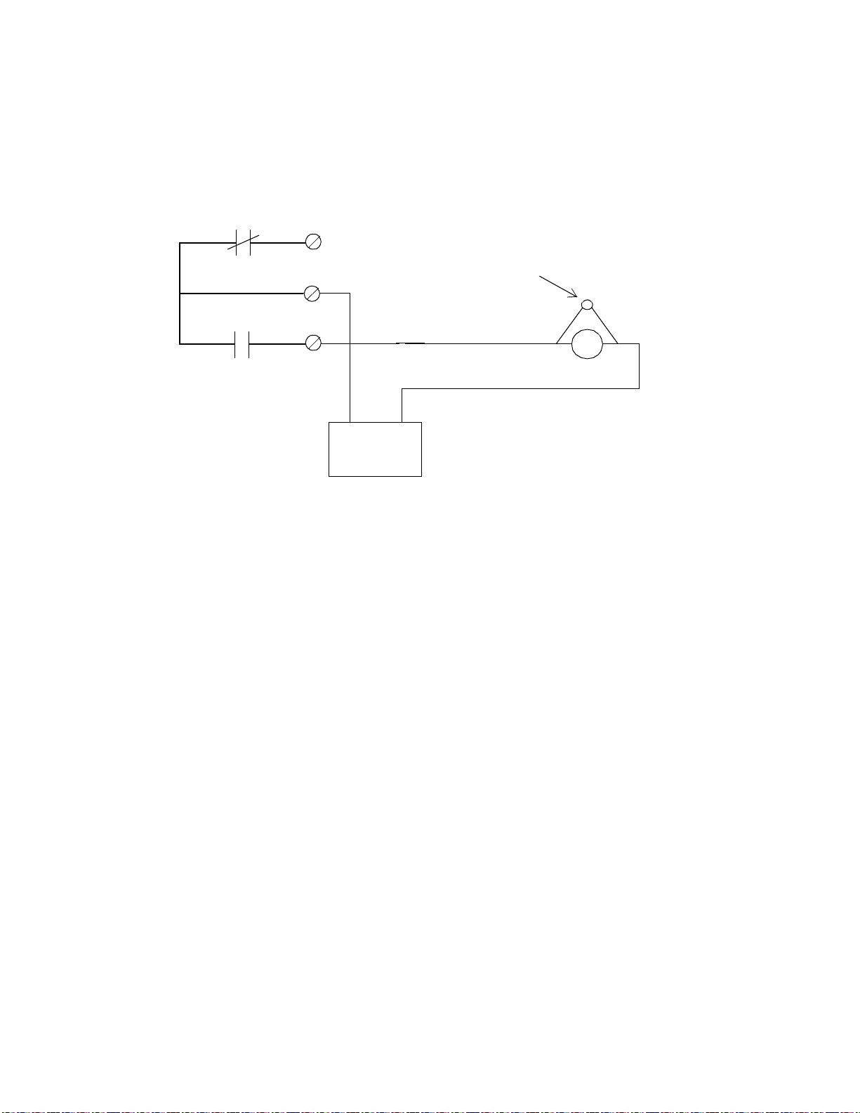
Figure 19 shows the schematic for wiring a DOOR or AUX output if the
circuit is normally open.
Figure 19. Wiring Diagram for DOOR a nd AUX Form C Outputs if N ormally
Open
NC
Oxide Metal
Varistor
(Andover #01-2020-095)
C
NO
C
+ –
Door Strike
(UL listed burglary-
12/24V
resistant electric
locking mechanism
Power Supply
(UL listed power
(CVXY) for
UL listed systems)
supply (APHV) for
UL listed systems)
This configuration shows a normally deenergized lock (when secured)
in a fail secure mode. Always be sure to use “panic” hardware that allows emergency exit from the secured area.
ACX 780/781 Installation Guide 35
Page 42

Hardware Instal lation
Figure 20 shows the schematic for wiring a DOOR or AUX output if the
circuit is normally closed.
Figure 20. Wiring Diagram for DOOR a nd AUX Form C Outputs if N ormally
Closed
NC
C
NO
Electromagnetic
C
Door Lock
(UL listed burglaryresistant electric
locking mechanism
12/24V
(CVXY) for
UL listed systems)
Power Supply
(UL listed power
supply (APHV) for
UL listed systems)
This configuration shows a normally deenergized lock (when secured)
in a fail secure mode. If power loss occurs, the lock circuit opens.
36 Andover Controls Corporation
Page 43

Hardware Installation
Powering Up the ACX 780/781
Warning
Before powering up the controller, be sure the board is jumpered for the
correct input voltage.
Before you proceed, be sure the following are correct:
1. Be sure the battery is conne cte d.
2. Be sure the AC power source is wired properly. Check to be sure all three
wires have been connected.
3. Be sure the controller has a true earth ground.
4. Be sure you have used the proper cables/wires and the correct lengths.
5. Be sure you have properly labeled the tag with the name of the
controller before removing the tag.
6. Be sure the Infinet cable has been properly wired.
7. Be sure the Infinet cable shields are properly connected.
If you have completed all previous sections in this manual, you are now
ready to power up the controller.
Turn on the AC power source (or close the power connection) and
switch AC power to ON. The controller starts automatically. The following occurs (also occurs when you press RESET):
1. If the controller has been off, relays remain off. If you have pressed
RESET, relays deenergize.
2. While you press RESET, all power LEDs on the Power Supply
Status Display light up.
ACX 780/781 Installation Guide 37
Page 44

Hardware Instal lation
Figure 21 shows the display. It is located in the upper left corner of the
unit, to the right of the Infinet connectio n.
Figure 21. Power Supply Status Display
SCAN
ERROR
NO SRV
CPU
+5V
+24V
+14V
-15V
-5V
AC PWR
3. The SCAN light on the front of the cabinet begins flashing at a rate
determined by the number of points and programs you have set up.
Figure 22 shows the status lights on the front door of the cabinet.
Figure 22. Status Lights on Front Door of Cabinet Provided
Status Lights on
Cabinet Door That
Correspond to
Doors Wired to
ACX780
Outputs 1 through 8
SCAN
ERROR
Status
NO SRV
AC ON
TD
RD
38 Andover Controls Corporation
OUTPUT9
Page 45

Hardware Installation
4. The CPU light on the Power Supply Status Display (inside cabinet)
begins flashing and flashes every .1 sec if all is normal. If the
controller fails a ROM test, the CPU light flashes every .2 sec. If the
controller fails a RAM test, the CPU light flashes every .025 sec. If
the controller fails any other software test, it flashes every .05 sec.
5. The AC_ON light on the front of the cabinet tur ns on and remains
on as long as the unit is receiving power.
6. The TD light (for Infinet) may not flash at this time. Once you have
set up the Infinet controller in the software and assigned the
controller an ID, the TD light imm e diate ly s tarts fla s hing to s how
data is being transmitted.
7. The RD light (for Infinet) begins flashing only if data is being
received from other controllers on the network. This may not happen
immediately.
8. If any of the nine door outputs is not set to AUTO, the OVERRIDE
light (inside cabinet) remains steadily on.
9. The status lights on the front door of the cabinet, labeled with output
numbers, turn on if the output value is ON (see Figure 24).
Figure 23 shows the status lights inside the cabinet, that also turn on
when the output value is ON.
Reset Button
The RESET button is the small button just to the left of the logo on the
board (near the top). You press it to res ta rt the c ontroller without era s ing memory. The same events occur as described above.
ACX 780/781 Installation Guide 39
Page 46

Figure 23. Location of Override and Status Lights
Override Light
Hardware Instal lation
ON
OFF
AUTO
ON
OFF
AUTO
ON
OFF
AUTO
ON
OFF
AUTO
ON
OFF
AUTO
ON
OFF
AUTO
ON
OFF
AUTO
ON
OFF
AUTO
ON
OFF
AUTO
OVERRIDE
OUTPUT 1
OUTPUT 2
OUTPUT 3
OUTPUT 4
OUTPUT 5
OUTPUT 6
OUTPUT 7
OUTPUT 8
OUTPUT 9
OUTPUTS
NC
1
C
NO
NC
2
C
NO
NC
3
C
NO
NC
4
C
NO
NC
1
C
NO
NC
6
C
NO
NC
7
C
NO
NC
8
C
NO
NC
9
C
NO
Status Lights on
if Output Is ON
Connecting Main Batteries
The two batteries at the base of the controller cabinet are 12-V 6.5 A-hr
batteries in series. The twisted pair wire to connect them runs from the
power supply to the batteries:
1. Connect the wire to the batte ry terminal. It is a solderle s s
connection.
2. Be sure to connect the red wire to the positive terminal, the black to
the negative.
40 Andover Controls Corporation
Page 47

Hardware Installation
Connecting the Andover Controls Service Tool
The SERVICE PORT is on the far left side of the controller just below
the Infinet connection. This port is to connect the Andover Controls
Service Tool to an ACX 780/781. The service tool accesses all ACX 780/
781s and other Infinet controllers on the same network. For information
on availability of the Andover Controls Service Tool, contact your Andover Controls representative.
ACX 780/781 Installation Guide 41
Page 48

Hardware Instal lation
42 Andover Controls Corporation
Page 49

Appendix
Underwriters Laboratories
Requirements
This appendix explains all requirements for installing the ACX 780/781
in a UL listed system.
ACX 780/781 Installation Guide A-1
Page 50

The ACX 780 is listed by Underwriters Laboratories , Inc. for standard
UL 294, Access Control System Uni ts, as a stand-alone unit. The ACX
780 must be kept in the UL listed enclosure provided.
You must install the controller and accessories in accordance with the
UL requirements stated in this manual to have a UL listed access control
system. Failure to install the access control system in accordance with
the UL requirements liste d in this manua l is a violation of the lis ting
mark of Underwriters Laboratories.
UL has examined th e ACX 780 controller with Sensor Engineering card
reader model 30387. For other accessories (door switches, door locks,
etc.) and specific two-wire inputs you should use in UL listed systems,
consult the UL listings. The exit push button and its wiring must be installed inside the secured area.
UL has not examined the operation of the door switch input, lightning
arrestors, keypad input, or the Andover Controls metal oxide varis tor
with the ACX 780. (For varistors you shou ld use in UL listed sys tems,
consult the UL listings.) UL has not examined connection and operation
with the Infinet.
This system does not provide for standby power in accordance with
UL294.
For UL listed systems, all wires connected to the panel should be in dedicated, grounded conduit.
For a UL listed system, when wiring a fail secure door strike, you
should use listed panic hardware to allow emergency exit from the secured area.
For information on how to program the controller and modules, refer to
the Infinity CX Programmer’s Guide, #30-3001-166 or the SX 8000
Programmer’s Guide # 30-3001-174. (P lease note that the keypad option is not intended for UL listed sy stem s. )
A-2 Andover Controls Corporation
Page 51

30-3001-392 ACX 780/781 Inst allation Guide Rev F
 Loading...