

Page 1
Order No. 30-3001-202
ACC EMX 190
Installation Guide
Your warranty is effective for 18 months starting on the
date the system is shipped.
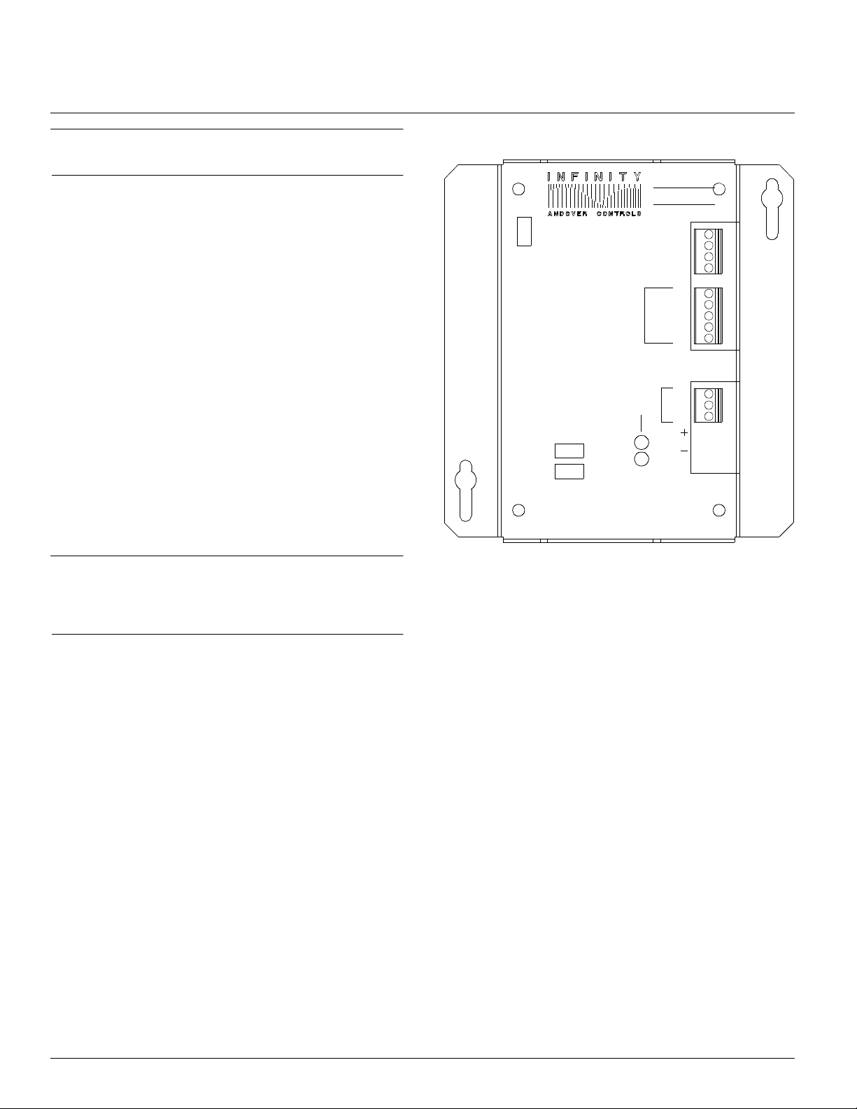
Figure 1 shows the EMX 190 module. This module is listed
by Underwriters Labora tories, Inc. for use with th e open
class ACX 700 controller. For information on UL require-
ments and enclosure si ze, see the ACX 700 Installation
Guide.
Before You Begin
You can connect one or more EMX modules to most Infinet
controllers that ha ve an expansion port. (UL listed systems
can have only two EMX 190 modules.) The particular controllers are cove red in the ACC EMX Modules Configurat ion
Guide (also enclosed with this product).The c onfiguration
guide also tells how many inputs and outputs are allowed for
any particular contr oller. Before you proceed, be sure the
controller allows m odules and the number and type of modules you plan t o use.
Figure 1. The
BOARD
WIEGAND
EMX 190
1
2
OVERRIDE
OFF
ON
CARD READER
Module
CARD
READER
INPUT
AUTO
ABA
EMX190
DOOR SWITCH
EXIT REQUEST
OVERRIDE
DOOR
OUTPUT
RTN
RTN
RTN
0-CLK
1/DATA
LED
+5V
NO
24VDC
CLASS
II
Version C
NC
C
Warning
Be sure wiring a nd installations c omply with local, state,
and national electric al codes.
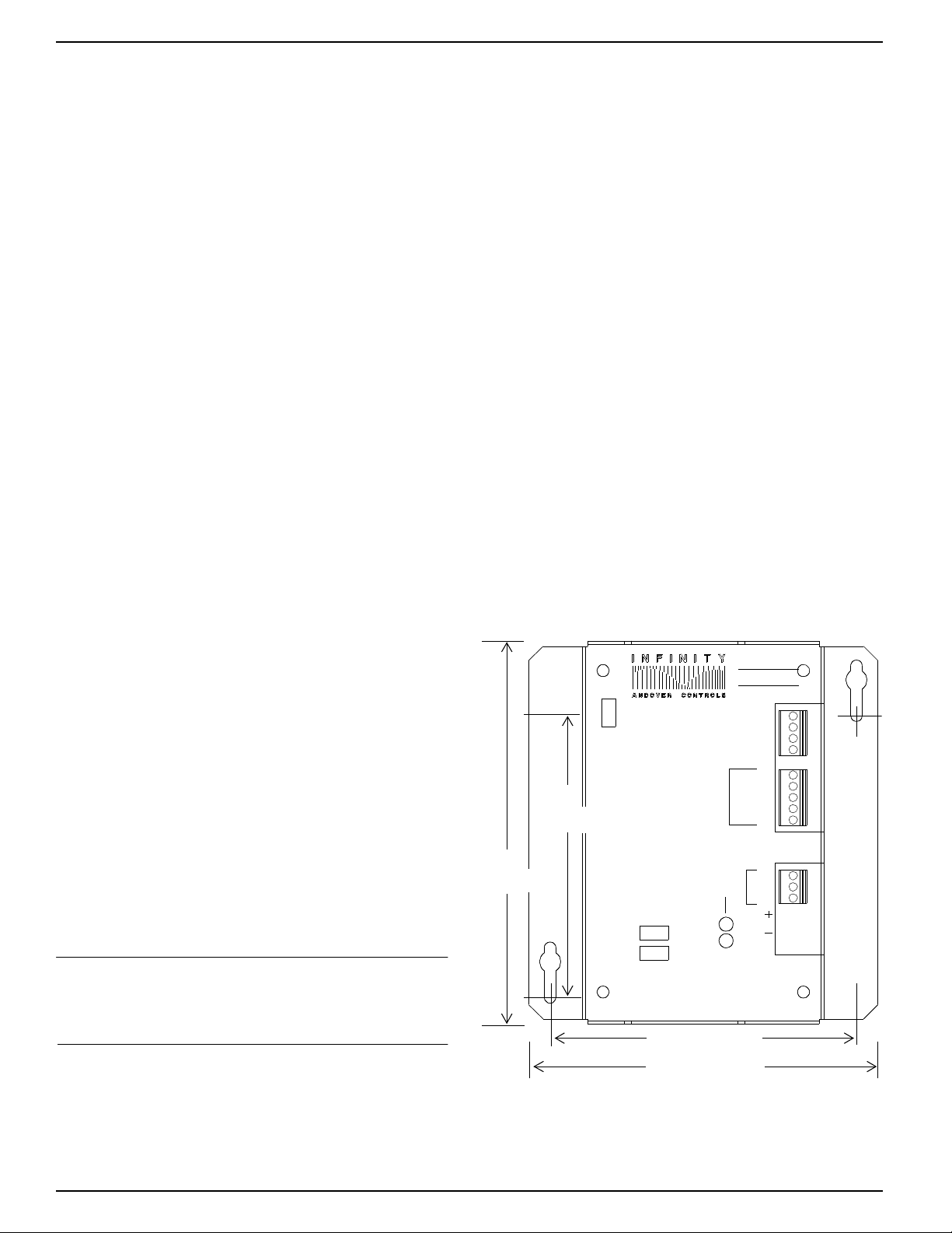
Dimens ions
Each EMX 19 0 module is approximately 6.72 × 6.13 × 1.82 in.
(171 × 156 × 46 mm).
Power Requirements
The first module receives power from the controller and op-
±
erates on 24
2 VDC. You can add an additional EMX 190 or
modules other than an EMX 190 if you have a n external pow-
±
er supply source of 24
2 VDC and properly c onnect the
modules to it. See the ACC EMX Modules Configuration
Guide for more infor mation.
The EMX 190 consumes up to 80 mA at 24 VDC.
Enviro nmental Requirements
The EMX 190 operates in the same environment that any
Infinet controll er operates in.
Input Requirements
Each module has the following three inputs:
• One door switch that indicates the status of the door—
open or closed. Must have a 10 KΩ resistor in series if
normally closed o r in parallel i f normally o pen. Required.
• One motion sensor tha t determines someone is
approaching the door or a push button that you must press
to leave the area. Must have a 10 KΩ resistor in series if
normally closed or in parallel if normally open. Optional.
• One card reader input that receives the Andover
standard Wiegand format.
You may also use a card re ader that receives the standard
ABA format if and only if you attach the Module EMX
190A to an ACX 700 controller. With all other co ntrollers,
you must use Andover’s sta ndard Wiegand format. The
card reader may have an LED, but does not have to.
The cards for the reader may be u p to 64 bits long f or a
EMX 190 or 256 bits long for an EMX 190A.The EMX
190 reads the standard Andover cards. The EMX 190A
reads only ABA-formats.
Copyright © 19 97 Andover Contro ls Corpo ration, 300 Brickstone Square, Andover, MA 01810 All Rights Reser v ed.
Downloaded from - http://www.guardianalarms.net
Page 2
Maximum data rate for the ca rd reader—1 ms between
bits with a 50 µs bit width.
Maximum power card reader should c onsume—35 mA
at 5 VDC.
The cable to the rea der can be up to 20 0 ft. (60 m) long
with five #22 gauge (0.35 mm2) wires and 100%
shielded. Or you may use up to 500 f t. (152 m) with five
#18 gauge (1.00 mm2) wires, also 100% shielded.
Your Andover Controls represe ntative can provide more
detail on specific inpu ts available.
(UL listed systems require tha t all wiring to t he unit be in
dedicated, grounded conduit.)
2. Look at the EMX 190 module. Notice that it has a
connector on the top and on the bottom. Plug the top
connector into the Infinet controller.
3.If you are connecting more than one EMX 1 90 module to
your Infinet controller, connec t the second one to the
bottom of the first. To use more than two modules
total, you must connect an external power source to t he
third module in the chai n.
4.Set the BOARD switch to 1 on the fir st EMX 190 on the
controller, and the BOARD switch to 2 on the second
EMX 190. If you do not plan to connect more than one
EMX 190, you should set the BOARD switch to 1.
Output Requirements
The output is a ReaderDoor or Door type that controls a
door through a card reade r. The output is a Form C relay,
which you wire like a digital/pu lsed output.
Resolution of the output is 0.1 sec. You may choose to
manually override the output by setting the OVERRIDE
switch to ON or OFF. Or you can set it to AUTO to have
the card reader control access through the door.
The OVERRIDE LED indicates the door output is on manual
contr ol ; th e DOOR OPEN L ED in dic ate s t he doo r is op en.
Install the EMX 190
1. Unpack
Be careful when unp acking the unit or units to not damage
the packaging material —you must reuse i t if yo u shi p the
product back for repair.
Never set two modules of the same model number to the
same board number.
3. Mount the Module
To mount the module along with the Infinet c ontroller inside a UL listed en closure, refer to the dimensi ons shown
in the next figure or in the ACX 700 Installation Guide.
Figure 2 shows the EMX 190 mounting dimensions.
Figure 2. The
4.95
(126 mm)
EMX 190
BOARD
1
2
Mountin g D im ensions
EMX190
DOOR SWITCH
EXIT REQUEST
CARD
READER
INPUT
RTN
RTN
RTN
0-CLK
1/DATA
LED
+5V
2. Connect to the Infinet Controller
Connect the module to the Infi net contr oller as ou tlined in
the steps that follow.
Caution
Be sure you disconne ct the In finet contr ol ler’s AC power
source before you connect any modules.
1.Look at the bottom panel of your Infinet contr oller. On
that panel is an expansion port in approximately the
center of the panel.
EMX 190 Installation Guide-2
6.72
(171 mm)
ON
WIEGAND
OVERRIDE
OFF
AUTO
ABA
CARD READER
5.38
6.13
DOOR
OUTPUT
24VDC
CLASS
OVERRIDE
(137 mm)
(156 mm)
NO
II
NC
C
Page 3

4. Connect the External Power Supply
(if necessary)
If you are installing multiple modules, you need an external
power supply. To determine exactly the groups of modules
you can attach, refer to the ACC EMX Modules Configura-
tion Guide.
Figure 4. Jumper Positi ons for In ternal an d External
Power Supplies
Jumper Position,
Internal Power
a
Supply
a
Indicates position for UL listed systems.
Jumper Position,
External Power
Supply
Figure 3 shows where you connect the external power
supply to the 2-pin Berg typ e connector on the EMX 190. It
also shows the location of the jumper you must reposition
if you use external power.
Figure 3. Lo c at ion of External P ow er Connection
and Jump er f or External Pow er
EMX190
BOARD
1
2
OVERRIDE
OFF
ON
WIEGAND
CARD READER
CARD
READER
INPUT
AUTO
ABA
DOOR SWITCH
EXIT REQUEST
OVERRIDE
DOOR
OUTPUT
RTN
RTN
RTN
0-CLK
1/DATA
LED
+5V
NO
24VDC
CLASS
II
NC
C
Connect
External
Power
Supply
Here
You change the jumper position only on the module or modules connected to the external power supply, not on an y o t her
modules .
Note
You need to change the jumper position only on the module(s) actually c onnect ed to an externa l power supply.
Never change the jumper position of other modules.
Wire the Inputs
Wire the Door Switch and Motion Sensor
Wire the door switch as follows:
1.Slip the appropri ate wire under the IN1 screw and
tighten the screw down on it.
Figure 5 shows the wiring diagram for the input if the
door switch is normally closed.
Figure 5. W iring Diagram fo r D oorSwitch In put f or
Norma lly C los ed Door Switch
Power
Supply
Jumper
Notice the locations of the inputs, the output and the override switch (you can set it to ON, OFF, or AUTO).
5. Reposition Jumper on One Module
The Berg type connector immedi ately belo w the external
power supply connection has a jumper t hat you r eposition
to indicate you are using external power.
Figure 4 shows the jumper in the two possible positions,
one for the internal power supply, the other for the extern al.
Each jumper is set to the internal positi on when you receive
it.
EMX 190 Installation Guide-3
RTN
IN1
Ω
10 K
Figure 6 shows the wiring diagram for the input if the
door switch is normally open.
Figure 6. W iring Diagram fo r D oorSwitch In put f or
Norma lly Open Door Swit c h
RTN
Ω
10 K
IN1
2.Slip the ground wire under the RTN1 screw and tigh ten
the screw down on it.
Page 4

Figure 7. Wiring Wiegand Ca rd Reader (Sensor Engine ering) to Modu le
Card Reader
+5VDC
DATA1
DATA0
LED
GND
3.Repeat the above steps for the moti on se nsor, only wire
it to the IN2 and RTN2 terminal.
Red
White
Green
Brown
Black Red
Wire Wiegand Card Reader (Sensor Engineering)
Wire the Sensor Engineering Wiegand card reader as follows:
1.Look at the wire connect ion on your Wiegand card
reader. Notice that you have five connec tion points:
• + 5VDC
• DATA1
• DATA0
• LED
• GND
2.Wire the first end of each wire to the appropr iate
connection point on the card reade r. The rec ommended
colors are as fo llows:
EMX 190
Black
Shield
Green
White
Brown
RTN
0/CLK
1/DATA
LED
+5V
7.Slip the black wir e and the shield unde r the RTN screw
and tighten the screw down on it.
8.Tie back the shie ld at t he card reader end and any wires
you do not use.
Wire Proximity ASR 110/112 Card Reader
The Proximity card reader requires a 12VDC power supply.
You wire the card r eader as follows:
1. Look at the wire connections on your Wiegand card
reader:
•0
•1
• LED
•+12
• GND
• +5 VDC—Red
• DATA1—White
• DATA0—Green
• LED—Brown
• GND—Black
3.Slip the other end of the red wire under the +5 V screw
on the module and tighten the screw down on it.
4.Slip the other end of the white wire under the 1/ DATA
screw on the module and tighten the screw down on it.
5.Slip the other end of the green wire under the 0/CLK
screw on the module and tighten the screw down on it.
6.Slip the other end of the brown wire under the LED
screw and tighten the screw down on it.
Figure 7 illustrates where you connect the various wires .
2.Wire the first end of five wires to the appropriate
connection point:
• 0—White
•1—Green
• LED—Brown
• + 12—Red
• GND—Black
3.Tie back the shield at the card reader end.
4.Slip the other e nd of the white wire under the 1/DATA
screw on the module and tighten the screw down on it.
5.Slip the other end of the green wire unde r the 0/CLK
screw on the module and tighten the screw down on it.
6.If the module has an LED, slip the other end of the brown
wire under the LED sc rew on the module and tighten the
screw down on it.
EMX 190 Installation Guide-4
Page 5

Figure 8. Pro x im it y W iegand Card Reader to Mod ule
0
1
LED
+12
GND
Green
White
Brown
Red
Black Red
Card Reader
Figure 9. Wiring ABA Card R eader to Modu le
SHIELD
Red
Black
+
–
+12VDC
Power Supply
Black
Green
White
Brown
EMX 190
(Three wi res
RTN
go to RTN)
0/CLK
1/DATA
LED
+5V
Card Reader
+5V
LED
DATA
CLK
COMMON
7.Wire the other end of the red wire to the positive
terminal of a 12 V power supply.
8.Wire an extensio n black wire to the negative terminal of
the 12 V power supply.
9.Take the other end of the extension black wire from the
12V pow er su pply , the oth er e nd of the cable black
wire, and the end of the shield. Slip all of them under
the RTN screw on the module; tighten the screw down
on them.
Red
Brown
White
Green
Black Red
EMX 190A
Black
RTN
Green
White
Brown
0/CLK
1/DATA
LED
+5V
2. Wire the first end of each wire to the appropriate
connection point on th e card re ader. Th e recommended
colors are as follows:
• +5—Red
• LED—Brown
• DATA—White
• CLK—Green
• GND—Black
Figure 9 illustrates where you connect the various wires.
Figure 8 illu str at es where you connect the various
wires.
Wire the ABA Card Reader (190A only)
You wire the ABA card reader as follows:
1.Look at the wire connecti ons on your ABA card reader:
•+5
• LED
• DATA
•CLK
• CO MMON
EMX 190 Installation Guide-5
3.Slip the othe r end of the red wire under the +5 V screw
on the module and tighten the screw down on it.
4.Slip the other end of the brown wire under the LED
screw and tighten the screw down on it.
5.Slip the other e nd of the white wire under the 1/DATA
screw on the module and tighten the screw down on it.
6.Slip the other end of the green wire unde r the 0/CLK
screw on the module and tighten the screw down on it.
7.Slip the other end of the black wire under the RTN
screw and tighten the screw down on it.
Page 6

8.Tie back the shield as well as any wires you do not use.
Troubleshoot
If you would like to connect a different card reader, contact your Andover Controls repr es entative.
For information on how to assign an output number and
program the output as a Door, see the Andover Controls
Infinity CX Programmer’s Guide or the SX 8000 Pro-
grammer’s Guide.
If you have problems with the Infinet controller after installing the module, see the Infinity Network
Configuration Guide.
Ref e r to th e Infinity Network Configurat ion Guide for
information on how to troubleshoot network and power
supply problems.
Warning
This equipment has been tested and found to comply
with the limits for a Class A digital device, pursuant to
Part 15 of the FCC Rules . The se limits are designe d to
provide reasonable protection against harmful interference when the equipment is operated in a commercial
environment. This equipment generates, uses, and can
radiate radio frequency energy and, if not installed and
used in accordance wit h the instruc tio ns in this manua l,
may cause harmful interferenc e to radi o communications. Operation of this equipment in a resident ial area
is likely to c ause harm ful int erfere nce in whi ch case th e
user will be required to correct the interference at his
own expense.
EMX 190 Installation Guide-6
Note
This digital ap paratus does not exceed the Class A limits
for radio noise emissions from digital apparatus set out
in the Radio Interference Regulations of the Canadian
Department of Communications.
Avis
Le présent appareil numérique n’émet pa s de bruits radioélectriques dé passant les limites applicables aux
appareils numériqu es de la cl ass A prescrit es dans le Règlement sur le brouillage radioélectrique édicté par le
ministère des Communications du Canada.
 Loading...