

Page 1

Copyright © 1992 Andover Controls Corporation, 300 Brickstone Square, Andover, MA 01810 All Rights Reserved.Subject to change without notice.
Click for EMX Menu
Order No. 30-3001-199
ACC EMX 160
Installation Guide
Your warranty is effective for 18 months starting on the
date the system is shipped.
Before You Begin
You can connect one or more EMX modules to most Infinet
controllers that have an expansion port. The particular controllers are covered in the ACC EMX Modules Configuration
Guide (also enclosed with this product).The configuration
guide also tells how many inputs and outputs are allowed for
any a particular controller. Before you proceed, be sure the
controller allows modules and the number and type of modules you plan to use.
Warning
Be sure wiring and installations comply with local, state,
and national electrical codes.
Version B
Power Requirements
The first two modules receive power from the Infinet controller on-board power supply and operate on 24 to 26 VDC.
You can add additional EMX modules other than an EMX
160. Usually, one or two more modules may operate on internal power; then you must add an external power supply
source of 24 VDC and properly connect the modules to it.
(See the ACC EMX Modules Configuration Guide.)
The EMX 160 consumes up to 11 mA at 24 VDC.
Environmental Requirements
The EMX 160 operates in the same environment that any
Infinet controller operates in.
Input Characteristics
Digital inputs have the following requirements:
Figure 1 shows the EMX 160 module.
Figure 1. The EMX 160 Module
EMX 160
EXTERNAL
POWER
RET
IN1
IN2
RET
IN3
IN4
RET
IN5
IN6
RET
IN7
IN8
BOARD
1
2
Dimensions
• Input Impedance—24K
Ω referenced to 5 V
Counter inputs have the following requirements:
• Input Impedance—24K
Ω referenced to 5 V
• Filtering—Corner Frequency at 106 Hz –20 db/decade
Install the EMX 160
1. Unpack
Be careful when unpacking the unit or units to not damage
the packaging material—you must reuse it if you ship the
product back for repair.
2. Connect to the Infinet Controller
Connect the module to the Infinet controller as outlined in
the steps that follow.
Caution
Each EMX 160 module is approximately 6.13 × 5.72 × 1.52 in.
Be sure you disconnect the Infinet controller’s AC power
source before you connect any modules.
Downloaded from - http://www.guardianalarms.net
Page 2
Click for EMX Menu
1.Look at the bottom panel of your Infinet controller. On
that panel is an expansion port in approximately the
center of the panel.
2.Look at the EMX 160 module. Notice that it has a
connector on the top and on the bottom. Plug the top
connector into the Infinet controller.
3.If you are connecting more than one module to your Infinet
controller, connect the second one to the bottom of the first.
4.Set the BOARD switch to 1 on the first EMX 160 on the
controller, and the BOARD switch to 2 on the second
EMX 160. If you do not plan to connect more than one
EMX 160 module, the BOARD switch can be set to
either 1 or 2.
Never set two modules of the same model number to the
same board number.
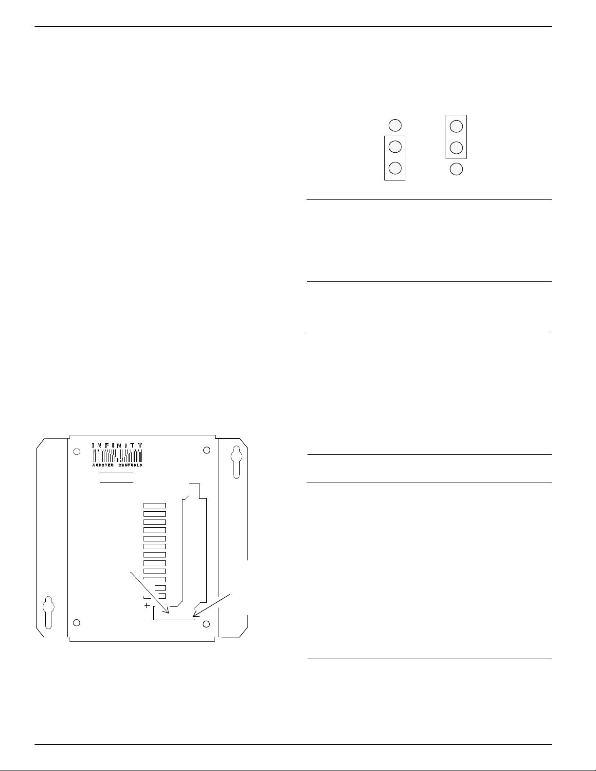
3. Connect the External Power Supply
Figure 3 shows the jumper in the two possible positions,
one for the internal power supply, the other for the external.
Each is set to the internal position when you receive it.
Figure 3. Jumper Positions for Internal and External
Power Supplies
Jumper Position,
Internal Power
Supply
Jumper Position,
External Power
Supply
Note
You need to change the jumper position only on the module(s) actually connected to an external power supply, not
on any other modules. Never change the jumper position of
other modules.
Wire the Inputs
If you are installing multiple modules, you may need an
external power supply. To determine what you need, refer
to the ACC EMX Modules Configuration Guide.
Figure 2 shows where you connect the external power
supply to the 2-pin Berg type connector on the EMX 160.
Figure 2. Location of External Power Connection
EMX160
Power
Supply
Jumper
EXTERNAL
POWER
RET
IN1
IN2
RET
IN3
IN4
RET
IN5
IN6
RET
IN7
IN8
BOARD
1
2
Connect
External
Power
Supply
Here
Caution
Do not remotely ground any part of the sensor wiring. Remote grounds connected to a return terminal could make
the controller operate incorrectly or damage the equipment. The signal return is not a true earth ground. It is an
electronic reference point necessary to interpret the sensor properly. Do not externally ground sensor or switch
terminals that return to the module or controller.
Caution
Although inputs usually function properly with unshielded sensor wire, you may need shielded wire if you run the
wire as follows:
• In the same conduit with other noise-generating
conductors such as 60 Hz AC power.
• In long runs close to large power-consuming or powergenerating equipment that can produce 60 Hz noise.
4. Reposition Jumper on One Module
The Berg type connector to the left of the external power
supply connection has a jumper that you reposition to indicate you are using external power.
We recommend you run input wiring in a conduit separate
from AC power or output wiring and avoid long wiring runs.
Page 3

Click for EMX Menu
Caution
Follow the rules below when wiring inputs:
• Bundle excess wires toward the back of the controller
cabinet to avoid any contact with circuit boards.
• Wires should never be within 1 in. of any component on
the printed circuit board.
• Be careful when stripping wire not to drop small pieces
of wire inside the module.
If you violate any of these rules, the controller could malfunction.
Notice that the inputs are to the right on the module. They
are labeled RET, 1, 2, RET, 3, 4, and so on. The RET
screw goes to the two input points that follow it.
You wire the inputs as follows:
1.Slip the first wire for the first sensor under the input
point screw for input 1 and tighten the screw down on it.
2.Slip the first wire for the second sensor under the input
point screw for input 2 and tighten the screw down on it.
3. Slip the ground wires from both the first and second
sensors under the RET screw above input point 1 and
tighten the screw down on them.
4. Slip the ground wires from both the first and second
sensors under the RET screw above input point 1 and
tighten the screw down on them.
5. Repeat the steps for each pair of inputs. Figure 4 shows
how a counter or digital input is wired.
Figure 4. Wiring Diagram for Counter/Digital Input
1 (input point 1)
RET (return)
Troubleshoot
If you have problems with Infinet controller after installing
the module, see the Andover Controls Infinet Controller
Troubleshooting Guide.This manual also contains information on how to test your inputs.Refer to the EnergyNet and
Infinet Configuration Guide to troubleshoot network and
power supply problems.
Warning
This equipment has been tested and found to comply with
the limits for a Class A digital device, pursuant to Part 15
of the FCC Rules. These limits are designed to provide
reasonable protection against harmful interference when
the equipment is operated in a commercial environment.
This equipment generates, uses, and can radiate radio frequency energy and, if not installed and used in accordance
with the instructions in this manual, may cause harmful
interference to radio communications. Operation of this
equipment in a residential area is likely to cause harmful
interference in which case the user will be required to correct the interference at his own expense.
Note
This digital apparatus does not exceed the Class A limits
for radio noise emissions from digital apparatus set out in
the Radio Interference Regulations of the Canadian Department of Communications.
Avis
Le présent appareil numérique n’émet pas de bruits radioélectriques dépassant les limites applicables aux
appareils numériques de la class A prescrites dans le Règlement sur le brouillage radioélectrique édicté par le
ministère des Communications du Canada.
Page 4

Click for EMX Menu
 Loading...