

Page 1
Copyright © 1992 Andover Controls Corporation, 300 Brickstone Square, Andover, MA 01810 All Rights Reserved.
Click for EMX Menu
Order No. 30-3001-278
ACC EMX 151
Installation Guide
Your warranty is effective for 18 months starting on the
date the system is shipped.
Before You Begin
You can connect one or more EMX modules to most Infinet
controllers that have an expansion port. The particular controllers are covered in the ACC EMX Modules Configuration
Guide (also enclosed with this product).The configuration
guide also tells how many inputs and outputs are allowed for
any a particular controller. Before you proceed, be sure the
controller allows modules and the number and type of modules you plan to use.
Warning
Be sure wiring and installations comply with local, state,
and national electrical codes.
Version 1.2
al EMX modules other than an EMX 151 if you have an
external power supply source of 24 VDC and properly
connect the modules to it. See the ACC EMX Modules
Configuration Guide for more information.
The EMX 151 consumes up to 70 mA at 24 VDC.
Environmental Requirements
The EMX 151 operates in the same environment that any
Infinet controller operates in.
Output Characteristics
You can wire the outputs as either voltage or current. The
voltage output has 2.5 mA maximum output over the
range of 0 to 10 VDC. The input impedance of the device
being controlled can be no less than 4000
Resolution of each voltage output is 2.44 mV.
Ω.
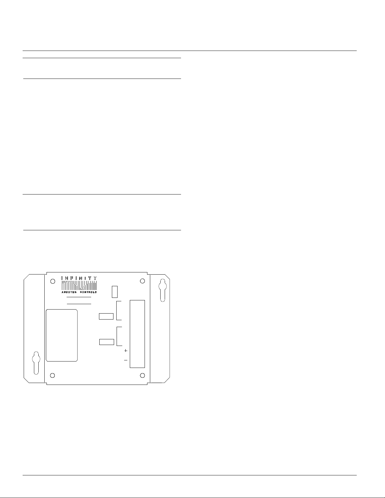
Figure 1 shows the EMX 151 module.
Figure 1. The EMX 151 Module
BOARD
1
EMX151
2
OUTPUT
A
OUTPUT
B
EXTERNAL
POWER
RET
RET
I
V
I
V
Dimensions
Each EMX 151 module is approximately 6.13 × 4.88 × 1.52 in.
The current output has a 0 to 20 mA control signal. The
input impedance of the device being controlled can be no
greater than 1000
Ω.
The circuitry that produces the 0 to 20 mA signal acts as a
“current sourcing device.” It sources the current to ground.
Resolution of each current output is 4.88
µA.
Accuracy of voltage and current is +/–0.1 % of the range
of the output.
1
Both outputs are fused at A.
--8
Install the EMX 151
1. Unpack
Be careful when unpacking the unit or units to not damage
the packaging material—you must reuse it if you ship the
product back for repair.
Power Requirements
The first module receives power from the controller and
operates on 24 VDC +/–15%/–5%. You can add addition-
Downloaded from - http://www.guardianalarms.net
2. Connect to the Infinet Controller
Connect the module to the Infinet controller as outlined in
the steps that follow.
Page 2
Click for EMX Menu
–
Caution
Be sure you disconnect the Infinet controller’s AC power
source before you connect any modules.
1.Look at the bottom panel of your Infinet controller. On
that panel is an expansion port in approximately the
center of the panel.
2.Look at the EMX 151 module. Notice that it has a
connector on the top and on the bottom. Plug the top
connector into the Infinet controller.
3.If you are connecting more than one EMX 151 module
to your Infinet controller, connect the second one to the
bottom of the first.
4.Set the BOARD switch to 1 on the first EMX 151 on the
controller, and the BOARD switch to 2 on the second
EMX 151. If you do not plan to connect more than one
EMX 151, you should set the BOARD switch to 1.
Never set two modules of the same model number to the
same board number.
4. Reposition Jumper on One Module
The Berg type connector immediately below the external
power supply connection has a jumper that you reposition
to indicate you are using external power.
You change the jumper position only on the module or modules connected to the external power supply, not on any other
modules.
Note
You need to change the jumper position only on the module(s) actually connected to an external power supply. Never
change the jumper position of other modules.
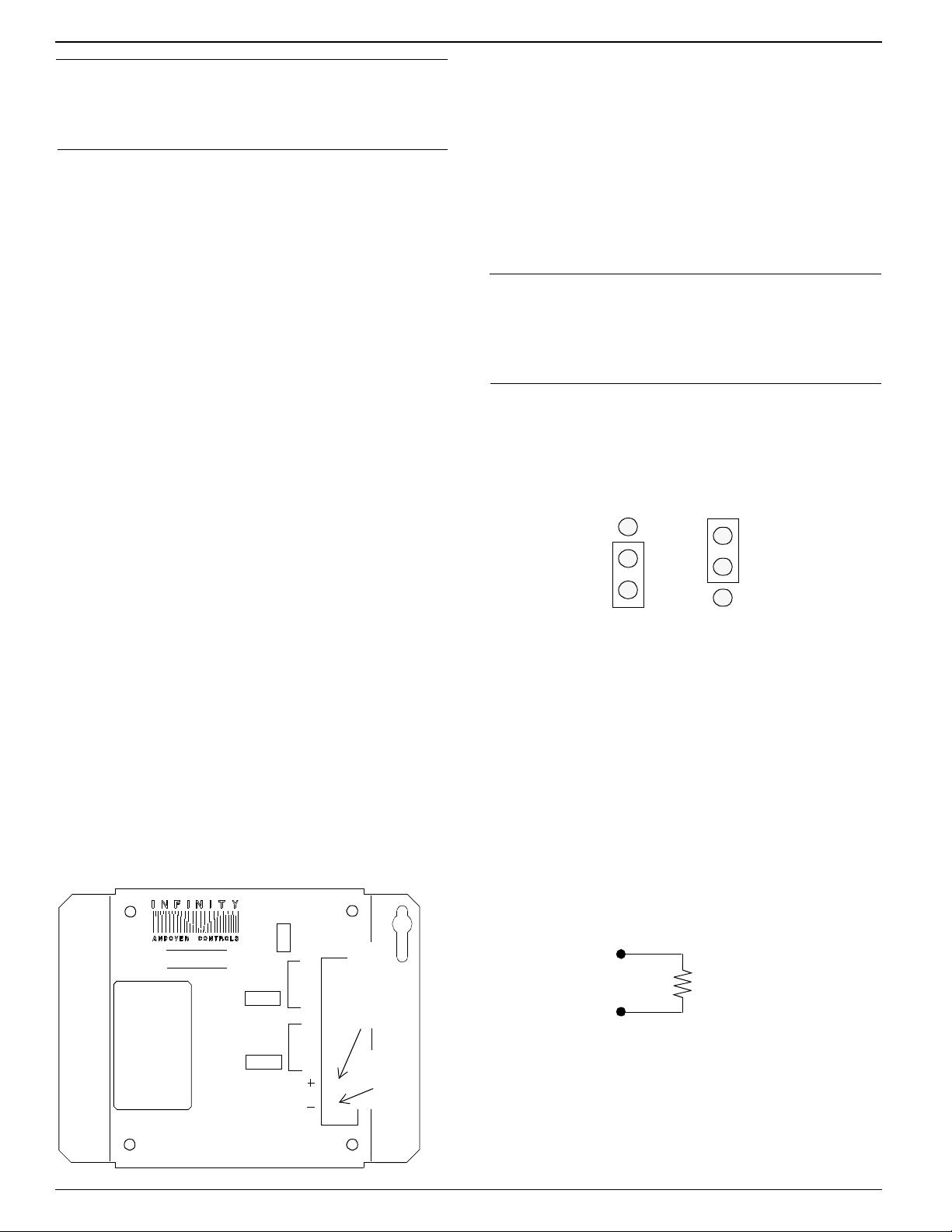
Figure 3 shows the jumper in the two possible positions,
one for the internal power supply, the other for the external.
Figure 3. Jumper Positions for Internal and External
Power Supplies
Jumper Position,
Internal Power
Supply
Jumper Position,
External Power
Supply
3. Connect the External Power Supply
(if necessary)
If you are installing multiple modules, you may need an
external power supply. To determine what you need, refer
to the ACC EMX Modules Configuration Guide.
Figure 2 shows where you connect the external power supply to
the 2-pin Berg type connector on the EMX 151.
Figure 2. Location of External Power Connection
and Jumper for External Power
BOARD
1
EMX151
2
OUTPUT
A
OUTPUT
B
EXTERNAL
POWER
RET
RET
Connect
External
Power
I
V
Supply
Here
I
V
Power
Supply
Jumper
Each is set to the internal position when you receive it.
Wire the Outputs
Wire Voltage Outputs
You wire the outputs for voltage as follows:
1. Slip the appropriate wire under the V screw and tighten
the screw down on it.
Figure 4 illustrates the wiring for voltage outputs.
Figure 4. Wiring Diagram for Voltage Outputs
V
+
RL > or = 4 KΩ
RET
2. Slip the ground wire under the RET screw and tighten
the screw down on it.
Wire Current Outputs
You wire the outputs for current as follows:
Page 3

Click for EMX Menu
Caution
Remember that the current sources to ground.
1.Slip the appropriate wire under the I screw and tighten
the screw down on it.
Figure 5 illustrates the wiring for current outputs.
2.Slip the ground wire under the RET screw and tighten
the screw down on it.
Figure 5. Wiring Diagram for Current Outputs
I
RL < or = 750 Ω
RET
Adjust the Outputs
and Troubleshoot
For information on how to assign output numbers, see the
Andover Controls Infinity CX Programmer’s Guide.
If you have problems with the Infinet controller after installing the module, see the Andover Controls Infinet
Controller Troubleshooting Guide.
Refer to the EnergyNet and Infinet Configuration Guide
for information on how to troubleshoot network and power supply problems.
Warning
This equipment has been tested and found to comply
with the limits for a Class A digital device, pursuant to
Part 15 of the FCC Rules. These limits are designed to
provide reasonable protection against harmful interference when the equipment is operated in a commercial
environment. This equipment generates, uses, and can
radiate radio frequency energy and, if not installed and
used in accordance with the instructions in this manual,
may cause harmful interference to radio communications. Operation of this equipment in a residential area
is likely to cause harmful interference in which case the
user will be required to correct the interference at his
own expense.
Note
This digital apparatus does not exceed the Class A limits
for radio noise emissions from digital apparatus set out
in the Radio Interference Regulations of the Canadian
Department of Communications.
Avis
Le présent appareil numérique n’émet pas de bruits radioélectriques dépassant les limites applicables aux
appareils numériques de la class A prescrites dans le Règlement sur le brouillage radioélectrique édicté par le
ministère des Communications du Canada.
Page 4

Click for EMX Menu
 Loading...