

Page 1

Engineer-to-Engineer Note EE-237
a
Technical notes on using Analog Devices DSPs, processors and development tools
Contact our technical support at dsp.support@analog.com and at dsptools.support@analog.com
Or vi sit our o n-li ne r esou rces htt p:/ /www.analog.com/ee-notes and http://www.analog.com/processors
Guide to Blackfin® Processor LDF Files
Contributed by Steve K Rev 1 – May 18, 2004
Introduction
This document describes the Linker Description Files (.LDF) supplied with VisualDSP++® 3.5. It is
intended for readers who are familiar with
processor
.LDF file by modifying an existing file or by writing one from scratch.
The document begins by explaining the intentions behind the various
3.5. Then it discusses concepts behind the elements of the Blackfin processor’s
the ADSP-BF533 Blackfin processor’s default
The document does not address the
.LDF files for the ADSP-BF561 Blackfin processor or those for use in
VDK applications.
.LDF files and are interested in customizing a Blackfin®
.LDF files included in VisualDSP++
.LDF files and examines
.LDF file in detail.
Default .LDF Files
For each of the following devices, VisualDSP++ provides four .LDF files:
• ADSP-BF531 Blackfin processors
• ADSP-BF532 Blackfin processors
• ADSP-BF533 Blackfin processors
• ADSP-BF535 Blackfin processors
• AD6532 processors
The name of each
optional suffix (e.g.,
If the
.LDF file name has no suffix, it is the “default .LDF file”. That is, when no .LDF file is explicitly
specified, the default file is used to link an application when building for that processor. For example,
ADSP-BF531.ldf is the default .LDF file for the ADSP-BF531 Blackfin processor. If no .LDF file is specified
explicitly via the
processor. The first of the following commands uses the default
specified file:
ccblkfn –proc ADSP-BF531 hello.c # uses default ADSP-BF531.ldf
ccblkfn –proc ADSP-BF531 hello.c –T ./my.ldf # uses ./my.ldf
.LDF file indicates the intended processor (e.g., ADSP-BF531.ldf) and may include an
ADSP-BF533_C.ldf).
–T command-line switch, the compiler driver selects the default .LDF file for the target
.LDF file, and the second uses a user-
Copyright 2004, Analog Devices, Inc. All rights reserved. Analog Devices assumes no responsibility for customer product design or the use or application of
customers’ products or for any infringements of patents or rights of others which may result from Analog Devices assistance. All trademarks and logos are property
of their respective holders. Information furnished by Analog Devices applications and development tools engineers is believed to be accurate and reliable, however
no responsibility is assumed by Analog Devices regarding technical accuracy and topicality of the content provided in Analog Devices’ Engineer-to-Engineer Notes.
Page 2

a
For each processor, there are three .LDF files with suffixes _C, _CPP, and _ASM (e.g., ADSP-BF533_C.ldf).
These
.LDF files are templates for the Expert Linker.
If you use the Expert Linker to create a custom
querying you for the kind of
.LDF file you want to create (Asm, C, or C++) and then copying one of the
above templates. The suffixes indicate the kind of
.LDF file for your project, the Expert Linker will do so by
.LDF files they support.
The CPP template is a superset of the C template, and the C template is a superset of the ASM template.
The differences are as follows:
• The CPP template links against C++ run-time libraries, C++ exception libraries, and the run-time
headers built to initialize C++ constructors. It maps data sections that contain information controlling
how thrown exceptions are caught.
• The C template is currently identical to the CPP template, since a C project may link against local or
system libraries that have been implemented in C++; there may be differences in a future release.
• The ASM template does not include a run-time header, and does not permit command-line arguments
to applications. The ASM template is not suitable for use with the compiler’s Profile-Guided
Optimization. Since the ASM template has no run-time header, it does not mandate a “start” symbol
resolved to the Reset address. It does not map the C++ exception sections into memory.
Blackfin Processor .LDF Concepts
The Blackfin processor’s .LDF files can be divided into five main areas:
• Preamble
• Library selection
• Run-time header selection
• Memory declaration
• Code/data-to-memory mapping
Each
.LDF file handles a variety of demands, allowing applications to be built in multiple configurations,
merely by supplying a few command-line options. This flexibility is achieved by extensive use of
preprocessor macros within the
variables within the
.LDF file to hold the name of a chosen file or other link-time parameter. This reliance
.LDF file. Macros serve as flags to indicate one choice or another, and as
on preprocessor operation can make the .LDF file seem an imposing sight.
Command-Line Options
In simple terms, different .LDF file configurations are selected by defining preprocessor macros on the
linker command line. This can be specified from the Link tab of the IDDE’s Project Options dialog box or
directly from the command line; for example:
ccblkfn –proc ADSP-BF533 prog.c –flags-link –MDUSE_CACHE
The command above defines the USE_CACHE macro during linking, and hence selects the .LDF file
configuration that allows for L1 code and data cache operation.
In contrast, leaving the macro undefined:
Guide to Blackfin® Processor LDF Files (EE-237) Page 2 of 12
Page 3

ccblkfn –proc ADSP-BF533 prog.c
a
specifies the default configuration, which assumes that code and data caches will not be enabled.
Macros may be defined in other ways. For example, under the Processor category of the Link tab (Project
Options dialog box), selection options include: use of various libraries, choice of floating-point library,
and what L1 memory is to be used. Ultimately, these selections define a macro during linking so that the
appropriate
The
L1 Memory Usage option provides two choices:
• Instruction and Data RAM
• Cache (sets USE_CACHE macro)
.LDF file option is selected.
As the name implies, the second choice sets the USE_CACHE macro, and the first choice leaves it unset, thus
achieving the same effect as the example above.
Other choices are more indirect, but operate in the same manner. The
Floating-point option also has two
choices:
• High performance
• Strict IEEE conformance
The second choice invokes the compiler driver with the -ieee-fp switch; the first choice invokes the
compiler without a floating-point switch, which selects the default behavior of
switches are effected by defining the
IEEEFP macro at link-time, or by leaving it undefined.
Other compiler switches are also implemented by passing macros to the linker to select
Build Variants and File Naming
-fast-fp. These compiler
.LDF file options.
The pre-built Blackfin processor libraries and run-time headers are available in numerous configurations,
and the various LDF options select between them. A naming scheme is used to append suffixes to the
libraries’ names, so that the
.LDF file can choose between them.
First, each file is built for a particular processor, or for a particular core. The majority of files are built for
a particular core, namely the ADSP-BF535 Blackfin processor or an ADSP-BF532 processor compatible
core. Such files have a suffix of
535 or 532. Some files (such as cplbtab531.doj) are built for particular
processors, which (as its name shows) was built for the ADSP-BF531 Blackfin processor.
In general, the processor/core naming does not count as one of the LDF options, because each
.LDF file is
dedicated to a particular processor already and refers to libraries using the appropriate processor/core
suffix.
Other suffixes do count as options, however, and the naming is slightly different between libraries and
run-time headers. The library suffixes are shown in Table 1.
Guide to Blackfin® Processor LDF Files (EE-237) Page 3 of 12
Page 4
a
d The library was built with symbolic information for debugging.
x The library was built with C++ exceptions enabled (that is, “-eh”).
y The library was built with all workarounds enabled (that is, with “-workaround all”).
mt The library was built with any multi-threading support present enabled (that is, with “-threads”).
Table 1. C Library File Suffixes
The only .LDF files to use the libraries built with multi-threading support (-threads) are the VDK .LDF
files, which are not covered in this document.
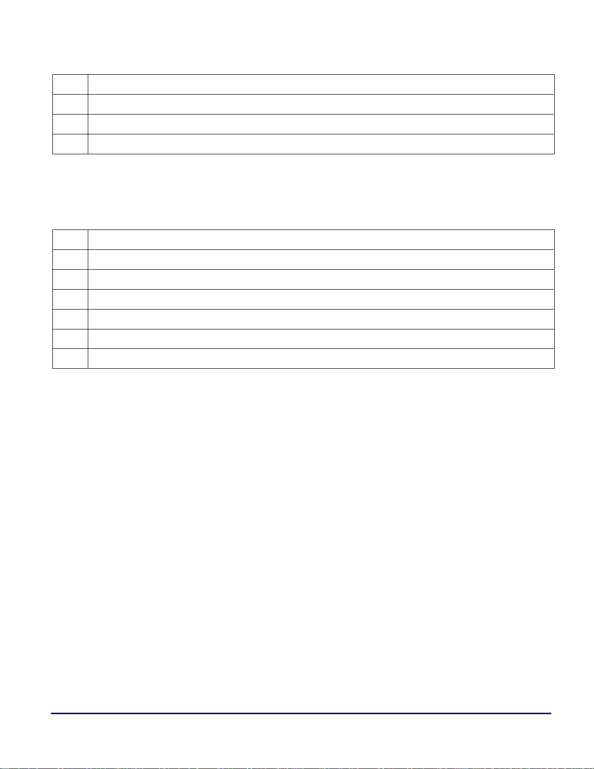
The run-time header file suffixes are shown in Table 2.
c The header will initialize C++ constructors
f File I/O support is included
mt Built with any multi-threading support enabled
n Not a run-time header; end-of-table marker for C++ constructor table
p Instrumented-code profiling included
s Leaves processor in Supervisor mode when calling main()
y Built with workarounds enabled.
Table 2. Run-Time Header File Suffixes
The .LDF file uses these suffixes in conjunction with command-line macros to determine which files to
link against. For example:
#ifdef __WORKAROUNDS_ENABLED /* { */
#define LIBSMALL libsmall532y.dlb,
#else
#define LIBSMALL libsmall532.dlb,
#endif /* } */
The __WORKAROUNDS_ENABLED macro is set by the compiler’s -workaround switch, and the LIBSMALL macro is
set to a value according to whether this switch is used. Later in the
.LDF file, LIBSMALL is used in the list of
libraries to link against.
C++ Constructor Table
C++ objects that exist at global scope must be constructed before main() is invoked, so their constructors
must be invoked from the run-time header.
For each compiled C++ module, the compiler creates a special data section, called
ctor. This data section
consists of pointers to the constructor functions for the global-scope objects.
The
.LDF files arrange for the list of objects to be:
Guide to Blackfin® Processor LDF Files (EE-237) Page 4 of 12
Page 5

run-time header, command-line objects, ctor-terminator
a
The run-time header places a label into ctor. Since the linker respects the ordering of objects, this label is
resolved to the start of the
follow, with the
ctor terminator (a NULL pointer) bringing up the rear. This means that the ctor section is
ctor section. Any ctor pointers to constructors from the command-line objects
assembled into a table of pointers-to-constructors that the run-time header walks through and processes.
Profile-Guided Optimization Support
Profile-Guided Optimization (PGO) is the process of gathering information about a running application
over many invocations of the executable with different input data, and then re-optimizing it using that
gathered information. The process relies upon the same application being run with different data sets,
which often means that the application acts upon sample data sets stored in files. More specifically, it
means that the application is instructed to process each file via command-line options passed to
The
.LDF files and the IDDE collaborate to provide support for command-line arguments. Under normal
main().
circumstances, a typical embedded program is not interested in command-line arguments, and receives
none. In these normal cases, the run-time header invokes a function to parse a global string
__argv_string[] and finds it empty.
To support PGO, the LDF option
__argv_string[] is mapped directly to the start of this section. The IDDE follows the convention that
IDDE_ARGS can be used to define a memory section called MEM_ARGV, and
command-line arguments can be passed to an application by writing the argument string into memory
starting at the beginning of
Memory Usage
MEM_ARGV.
The .LDF files define memory areas for all defined spaces on the processor.1 Not all of these memory areas
are used within the
.LDF files. Instead, the .LDF files provide two basic memory configurations:
• The default configuration specifies that only internal memory is available and caching is disabled.
Thus, no code or data is mapped to SDRAM unless explicitly placed there, and all of the available L1
space is used for code or data.
• The
USE_CACHE option selects the alternative configuration, where code and data caches are enabled
and external SDRAM is used. Code and data are mapped into L1 where possible, but the
Cache/SRAM areas are left empty; any spill-over goes into the lower 32 MB area of SDRAM.
If
USE_CACHE is used, caches may safely be turned on, because doing so will not corrupt code or data.
Selecting this option does not actually enable the caches — that must be done separately (for example,
through the
allows caches to be enabled later. Note that the SDRAM is not enabled automatically when
___cplb_ctrl configuration variable). Instead, this option ensures that the memory layout
USE_CACHE is
enabled.
A common user error is to enable cache despite not having specified
or data corruption as cache activity overwrites the contents of SRAM. Therefore, the
USE_CACHE, which would lead to code
.LDF files use the
following “guard symbols”:
1
With the exception of the core MMRs, which the linker considers “out of bounds”.
Guide to Blackfin® Processor LDF Files (EE-237) Page 5 of 12
Page 6

• ___l1_code_cache
• ___l1_data_cache_a
• ___l1_data_cache_b
a
These symbols are defined by the .LDF files and are given values (i.e., resolved to addresses 0 or 1),
depending on whether USE_CACHE is defined. The run-time library examines these symbols when cache
configuration is requested, and refuses to enable a cache if the corresponding guard symbol is zero,
indicating that valid information already occupies this space.
Input Sections
This section describes the content and intent of the various code and data sections generated by the
compiler and libraries, and mapped by the
The
.LDF files use the following code sections:
•
L1_code: by default, the compiler does not generate code here. The .LDF files map this section so that
.LDF files into memory areas.
the code that must go into L1 Instruction SRAM is placed there explicitly using the section directive.
This section is always the first section mapped into L1 Instruction SRAM.
•
cplb_code: the run-time library’s CPLB management routines are here. It is usually mapped into L1
Instruction SRAM. In particular, if CPLB-replacement is a possibility, this section must be mapped to
memory that is guaranteed to always available; this means that it must be addressed by a locked
CPLB.
•
program: the default code section generated by the compiler. If possible, code in this section will be
mapped into L1 Instruction memory; however, code will spill into slower memory if there is not
enough space.
The
.LDF files use the following data sections:
•
L1_data_a: by default, the compiler does not generate data here. This section is analogous to L1_code
in that it exists to allow data to be mapped explicitly into L1 Data A SRAM using the section
directive.
•
L1_data_b: similar to L1_data_a, except that it is used to map data into L1 Data B SRAM.
•
cplb_data: the run-time library’s CPLB management routines use CPLB configuration tables, which
are placed here. In particular, the
cplbtabx.doj files (where x indicates the target) mapped by the .LDF
files are placed into this section. It must be mapped to a data area that is always available. If CPLB
replacement is a possibility, this section must be mapped into memory that is covered by a locked
CPLB.
•
data1: the default section used for compiler-generated global data.
•
voldata: the compiler does not generate data for this section. It exists for data that may change due to
external influences (such as DMA), and should not be placed into cached data areas.
•
constdata: used for global data which is declared as constant, and for literal constants such as strings
and array initializers. The compiler’s default behavior is to assume that
constant, and therefore can be mapped into read-only memory (although the default
const data will remain
.LDF files do not
do this). The compiler’s behavior is different from the ANSI C Standard in this respect: under ANSI C
Guide to Blackfin® Processor LDF Files (EE-237) Page 6 of 12
Page 7

a
such const data could be altered by other means. For details, refer to the -const-read-write switch in
the VisualDSP++ 3.5 C/C++ Compiler and Library Manual for Blackfin Processors [1].
•
bsz: used for global uninitialized data, which is implicitly initialized to zeros, when the -bss switch is
specified. This section does not actually contain data; it is zero-filled upon loading via the IDDE, or
when processed by the loader. This section is not generated when the
-no-bss switch is used.
• bsz_init: holds a pointer to run-time initialization data generated by the Memory Initializer utility. It
is expected that this section will be mapped into read-only memory. When a
.DXE file has been
processed by the Memory Initializer utility and the program starts running, other data sections (such as
data1 and constdata) are initialized by data copied to from this section. If the Memory Initializer
utility is not being used, this section may be mapped to RAM.
The
.LDF files use the following generic sections:
• cplb: this section is historical, and is no longer used. It has been replaced with cplb_code and
cplb_data.
•
sdram0: this section allows code or data to be mapped explicitly into external memory by using the
section directive. This can be used to place large, infrequently used data or functions into external
memory to free up valuable internal memory.
The
.LDF files use the following “table” sections. In all cases, these sections may be mapped into read-
only memory. For a given section
mapped immediately after the section
s and its terminating section sl, the terminating section sl must be
s.
•
ctor: this section contains pointers to constructors for C++ objects. It is used to invoke the
constructors before
•
ctorl: this section contains the terminator for the ctor table section. It must be mapped immediately
after the
•
.gdt: Global Dispatch Table. Used by the C++ Exception Library to determine which area of code to
ctor section.
main() is called. It must be contiguous in memory.
which a particular address belongs. This section must be contiguous in memory.
•
.gdtl: this section contains the terminator for the .gdt table section. It must be mapped immediately
after the
•
.edt: Exception Dispatch Table. Used by the C++ Exception Library to map from try blocks to catch
.gdt section.
blocks.
• .
cht: Catch Handler Types table. This is used to map to the RTTI type information. The C++
Exception Library uses it to determine the types that correspond to catch entries for a
•
.frt: Function Range Table. This is used by the C++ Exception Library during exception processing
try block.
to unwind the stack of active functions.
•
.frtl: this section contains the terminator for the .frt table section. It must be mapped immediately
after the
.frt section.
Guide to Blackfin® Processor LDF Files (EE-237) Page 7 of 12
Page 8

a
ADSP-BF533.LDF in Detail
Preamble
The .LDF file begins with a brief comment that describes the options available within the .LDF file
(as determined by linker preprocessor macros). These options are explained in detail at the relevant stages
within the
The
the Blackfin processor
The
Blackfin\lib subdirectory of the VisualDSP++ installation directory. The linker sets $ADI_DSP to be the
VisualDSP++ installation directory.
The
linker will have no default place to search for run-time libraries. This option is selected by the
-no-std-lib compiler switch, which ensures that the application is being linked against user-supplied
libraries only.
Library Selection
.LDF file.
ARCHITECTURE directive specifies that this .LDF file is for the ADSP-BF533 Blackfin processor. All of
.LDF files are targeted specifically at a single processor.
SEARCH_DIR directive identifies the location of the standard run-time libraries as being the
SEARCH_DIR directive is not included if the __NO_STD_LIB option is selected, which means that the
This stage of the .LDF file builds up various macros and variables with the aim of producing the
$LIBRARIES list, a list of the library and object files searched to resolve references, in the required order.
Some of the options specify the selection of one library over another (e.g., the workarounds-enabled
version versus the normal version) and other options specify the selection of one library ordering over
another (e.g., the selection of fully-compliant IEEE floating-point support versus the higher-performance
version).
The
USE_FILEIO option is forcibly defined. This is necessary for printf() and other stdio-related
functions that are employed through much of the development cycle. Disabling the
disables all
stdio-related I/O operations.
USE_FILEIO option
A number of options relate to the instrumented-code profiler. The compiler has three switches for the
profiler:
-p, -p1, and –p2. For all three switches, the compiler instruments the code in the same way,
causing it to invoke the profiling library at the start and end of each instrumented function to gather
statistics. The three switches differ in how the resulting application reports its gathered data. The
switch writes the data to the
mon.out file; the –p2 switch writes it to the standard output stream; the -p
-p1
switch writes the data to both places. This difference in behavior is achieved by linking in different object
files, which is controlled by
.LDF file options.
The switches select the following LDF options:
•
-p selects USE_PROFILER
•
-p1 selects USE_PROFILER1
•
-p2 selects USE_PROFILER2
An additional option,
USE_PROFILER0, is set by the prelinker when it detects that an input object file has
been instrumented for profiling. This indicates that the profiling library must be linked against even if no
Guide to Blackfin® Processor LDF Files (EE-237) Page 8 of 12
Page 9

a
profiling switches were specified at link-time. USE_PROFILER is used to set USE_PROFILER0, interpreting the
lack of any link-time profiling switches as indicating that both output methods should be used.
The output method selection is determined by linking against a small object file that contains two global
variables. These variables indicate whether each output method has been selected. Several different object
files define the permutations of the two variables (see Table 2). Like other object files, several variants of
these files exist, such as the “normal” and “workarounds-enabled” variants. When an object is built with
workarounds enabled, different code is generated to work around known silicon anomalies. When the
object contains data only (no code), as in this particular case, the “workarounds-enabled” switches have
no effect and the “variants” are identical. These redundant multiple variants are still built to maintain the
naming conventions.
PROFFLAG is defined to be the name of one of these object files, should profiling be required. If it is not
required, PROFFLAG is left undefined.
OMEGA is the name of the file containing the idle routine. This routine is reached if the application
terminates voluntarily, such as by returning from
The
__WORKAROUNDS_ENABLED option is defined by the compiler driver whenever workarounds have been
main() or by calling exit().
requested at link-time; although there are options for selecting each available workaround individually
when compiling, it is infeasible to provide pre-built libraries for all combinations of workarounds.
Therefore, there is a single workarounds-enabled version of each library and object, built with all
workarounds selected.
MEMINIT holds the name of the object file that contains the pointer to any initialization data created by the
Memory Initializer utility. This pointer is a
NULL pointer unless the resulting application is processed by
the Memory Initializer. There are no variants of this file.
LIBSMALL is defined to be the name of the supervisor-mode library.
The
M3_RESERVED option is for the emulator. By default, the emulator uses the Blackfin processor’s stack
for workspace, but there is an option to use the
-reserve m3 switch to allow this, but there are a small number of routines that require additional handling.
For example, interrupt handlers may not save and restore
not. Therefore, two variants of some libraries are supplied to handle each case.
handlers,
performance when
setjmp() and longjmp(), while LIBDSP contains optimized DSP-related routines that lose some
M3 is reserved for the emulator.
M3 register instead. The run-time libraries are built with the
M3 if it is reserved, but they must do so if it is
LIBM3 contains exception
The floating-point libraries are selected by ordering. The fully-compliant library is a stand-alone library,
and the high-performance library is part of LIBDSP. The ordering of these two libraries is changed
according to the required floating-point library. The
IEEEFP option, set by the –ieee-fp compiler switch,
chooses the alternative ordering.
The libraries selected thus far are assembled into a
been built with C++ exceptions (the
–eh and –rtti switches) if __ADI_LIBEH__ is set (it is set by –eh at
link-time). The appropriate file I/O library is appended to this list, to complete the
LIBS list, optionally selecting C++ libraries that have
$LIBRARIES list.
Guide to Blackfin® Processor LDF Files (EE-237) Page 9 of 12
Page 10

CRT Selection
a
This stage selects the required pre-built version of the C run-time header (CRT), the startup code that
executes before
main() is invoked. This section chooses the CRT based on the values (defined or
otherwise) of four options:
• USE_PROFILER
• USE_FILEIO
• __cplusplus
• __WORKAROUNDS_ENABLED
The chosen object file is named with suffixes as described earlier in this document. For the latter three
options, a single object file is selected to be included in the
is also set to include the profiling library, and the
PROFFLAG file determined earlier.
$OBJECTS list. If USE_PROFILER is selected, CRT
For C++ builds (
__cplusplus option), ENDCRT is defined to be an object containing the end-of-table
terminator for the C++ constructor table. For other builds, it is left undefined.
The CRT and
ENDCRT are then included in the $OBJECTS list, along with $COMMAND_LINE_OBJECTS, which is
defined by the linker to be all the objects and libraries named on the linker’s command-line. The CPLB
definition-table object, used to configure cache settings, completes the
Between them,
items in
$OBJECTS.
Memory Declaration
$OBJECTS are linked into the application, and $LIBRARIES resolves symbols referenced from
$LIBRARIES and $OBJECTS name the sources used by the linker to resolve symbols. The
$OBJECTS list.
The Blackfin processor .LDF files define memories that correspond closely to the hardware memory map.
The
.LDF files have additional divisions so that memory can be suitably allocated to the different needs of
the run-time libraries, such as heap and stack.
The Core and System memory-mapped registers (MMRs) are at the top of the memory. The linker does
not allow a memory section to be defined for the Core MMRs; this memory declaration is commented out,
but left in for clarity.
The L1 Scratchpad is defined, but is not used by the
.LDF file. Note that statically-initialized data may not
be mapped into scratchpad.
L1 Instruction memory is divided into code and code-cache. Code-cache is selectable as cache or code
space.
L1 Data Bank B is divided into data and data-cache, with the former being further subdivided into space
for constant data and the stack. In general, the
.LDF files attempt to place the stack into fast L1 memory,
since the compiler often uses the stack for function parameters and temporary working-space.
L1 Data Bank A also has the cache/non-cache division. The non-cache area has an optional 256 bytes
reserved for command-line arguments. This
IDDE_ARGS option supports Profile-Guided Optimization, as
described previously.
Four banks of asynchronous memory are defined, along with a single bank of SDRAM. This latter bank is
the lowest bank of memory, a 32 MB space from which the lowest 16 KB has been claimed for the heap.
Guide to Blackfin® Processor LDF Files (EE-237) Page 10 of 12
Page 11

a
Note that the heap does not include address 0x0000 0000, which is reserved as the NULL pointer in C, and
may not be used to point to valid data.
Code/Data-to-Memory Mapping
The PROCESSOR directive writes the resulting .DXE file to $COMMAND_LINE_OUTPUT_FILE, which is defined by
the linker to be the output file name passed by the compiler driver.
The
start symbol (the first executable part of the CRT) is mapped directly to the processor’s Reset
address using the
RESOLVE directive. If Profile-Guided Optimization is used, the ___argv_string symbol is
mapped directly to the start of the arguments section by the same method.
The
_main and start symbols are explicitly named as being immune from linker elimination, in case that
option is enabled.
The remainder of the
The
.LDF file is general purpose and is intended to ensure that everything fits. Thus, sections like program
and
data1 are mapped to numerous output sections in different memory areas. When one memory section
.LDF file maps code or data from input sections to output sections via memory areas.
fills up, the remainder may go into other sections.
Some items are optionally mapped. C++ objects are mapped for C++ links only; code and data are
mapped into cache areas of L1 SRAM (or to external memory when the
The
BSZ sections are marked as ZERO_INIT, indicating to the (optional) Memory Initializer that the sections
should be emptied, and zero-filled at run-time. The
bsz_init section will contain the pointer to the start of
USE_CACHE option is specified).
the table produced by the Memory Initializer, and is ordinarily mapped into read-only memory; for
simplicity, it is mapped into a normal data section in the earlier stages of development.
The
.meminit section is handled differently by the linker. No code or data resides in .meminit during
linking. However, once linking is complete, the
in the memory area to which it is mapped. In this particular
MEM_L1_DATA_B, so that after linking, .meminit occupies the remaining portion of MEM_L1_DATA_B not used
by the
table. Like
.DXE file. This defines an empty space that the Memory Initializer can use to store the configuration
bsz_init, the .meminit section is ordinarily mapped into a read-only memory space.
.meminit section expands to consume all the unused space
.LDF file, .meminit is mapped to
The stack and heap spaces do not have data mapped into them by the .LDF file. Instead, they each define
global symbols that contain the addresses of their start, end, and length (for the heap). This allows the runtime library to determine the size and location of the stack and heap at runtime, so that either can be
modified easily within the
.LDF file. Note that the CRT requires these symbols.
Guide to Blackfin® Processor LDF Files (EE-237) Page 11 of 12
Page 12
References
[1] VisualDSP++ 3.5 C/C++ Compiler and Library Manual for Blackfin Processors. Rev 2.2. October 2003.
Analog Devices, Inc.
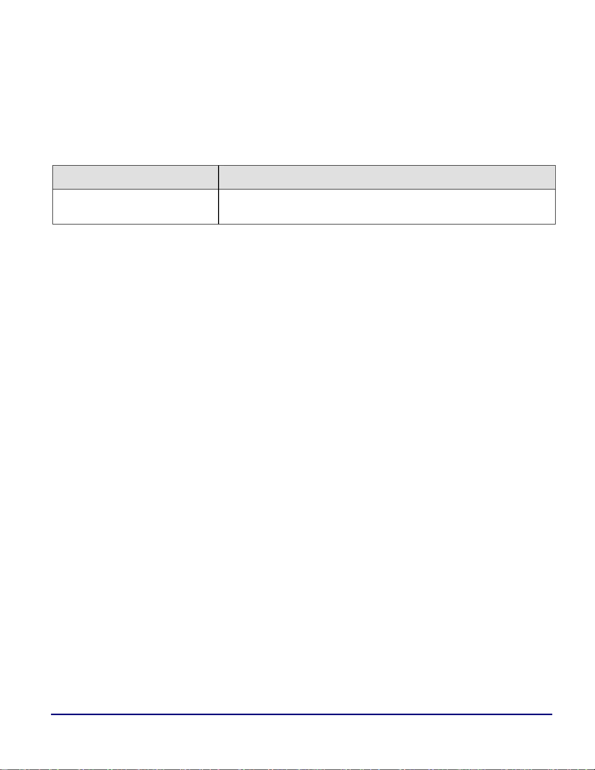
Document History
Revision Description
a
Rev 1 – May 18, 2004
by Steve K
Initial Release
Guide to Blackfin® Processor LDF Files (EE-237) Page 12 of 12
 Loading...