


PRM-4

PRM-4
Phase Sequence and
Motor Rotation Tester
Users Manual
Mode d’emploi•
Bedienungshandbuch•
Manuale d’Uso•
Manual de uso•

English
PRM-4
Phase Sequence and
Motor Rotation Tester
Users Manual
PRM4_Rev001
© 2007 Amprobe Test Tools.
All rights reserved.

2
Limited Warranty and Limitation of Liability
Your Amprobe product will be free from defects in material and workmanship for
1 year from the date of purchase. This warranty does not cover fuses, disposable
batteries or damage from accident, neglect, misuse, alteration, contamination,
or abnormal conditions of operation or handling. Resellers are not authorized
to extend any other warranty on Amprobe’s behalf. To obtain service during the
warranty period, return the product with proof of purchase to an authorized
Amprobe Test Tools Service Center or to an Amprobe dealer or distributor. See
Repair Section for details. THIS WARRANTY IS YOUR ONLY REMEDY. ALL OTHER
WARRANTIES - WHETHER EXPRESS, IMPLIED OR STAUTORY - INCLUDING IMPLIED
WARRANTIES OF FITNESS FOR A PARTICULAR PURPOSE OR MERCHANTABILITY, ARE
HEREBY DISCLAIMED. MANUFACTURER SHALL NOT BE LIABLE FOR ANY SPECIAL,
INDIRECT, INCIDENTAL OR CONSEQUENTIAL DAMAGES OR LOSSES, ARISING FROM
ANY CAUSE OR THEORY. Since some states or countries do not allow the exclusion
or limitation of an implied warranty or of incidental or consequential damages, this
limitation of liability may not apply to you.
Repair
All test tools returned for warranty or non-warranty repair or for calibration should
be accompanied by the following: your name, company’s name, address, telephone
number, and proof of purchase. Additionally, please include a brief description of
the problem or the service requested and include the test leads with the meter.
Non-warranty repair or replacement charges should be remitted in the form of a
check, a money order, credit card with expiration date, or a purchase order made
payable to Amprobe
®
Test Tools.
In-Warranty Repairs and Replacement – All Countries
Please read the warranty statement and check your battery before requesting
repair. During the warranty period any defective test tool can be returned to your
Amprobe
®
Test Tools distributor for an exchange for the same or like product.
Please check the “Where to Buy” section on www.amprobe.com for a list of
distributors near you. Additionally, in the United States and Canada In-Warranty
repair and replacement units can also be sent to a Amprobe
®
Test Tools Service
Center (see address below).
Non-Warranty Repairs and Replacement – US and Canada
Non-warranty repairs in the United States and Canada should be sent to a
Amprobe
®
Test Tools Service Center. Call Amprobe
®
Test Tools or inquire at your
point of purchase for current repair and replacement rates.
In USA In Canada
Amprobe Test Tools Amprobe Test Tools
Everett, WA 98203 Mississauga, ON L4Z 1X9
Tel: 877-AMPROBE (267-7623) Tel: 905-890-7600
Non-Warranty Repairs and Replacement – Europe
European non-warranty units can be replaced by your Amprobe
®
Test Tools
distributor for a nominal charge. Please check the “Where to Buy” section on www.
amprobe.com for a list of distributors near you.
European Correspondence Address*
Amprobe
®
Test Tools Europe
In den Engematten 14
79286 Glottertal, Germany
Tel.: +49 (0) 7684 8009 - 0
*(Correspondence only – no repair or replacement available from this address.
European customers please contact your distributor.)
3
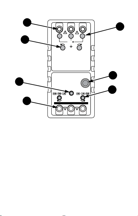
➊
Phase rotation input terminals
➋
Open phase indicators
➌
Phase rotation indicators
➍
Motor tester power switch
➎
Motor tester power indicator
➏
Motor rotation indicators
➐
Motor rotation input terminals
M1
M2
BATT
TEST
M3
L1
A B C
L2 L3
MOTOR ROTATION DETERMINED WHILE FACING MOTOR SHAFT
CAT
600V
MOTOR
ROTATION
TESTER
3-PHASE
TESTER
PRM-4
PRM-4
DO NOT CONNECT TO LIVE VOLTAGE!
1
4
6
3
5
2
7

4
PRM-4 Phase Sequence and
Motor Rotation Tester
CONTENTS
Safety Information ................................................................................... 5
Symbols Used in this Manual ...................................................................6
Introduction ..............................................................................................6
Making Measurements ............................................................................7
3-Phase Rotation Test ........................................................................ 7
Open Phase Test ..................................................................................7
Motor Rotation Test ...........................................................................8
Maintenance .............................................................................................9
Battery and Fuse Replacement ..........................................................9
Cleaning and Storage ......................................................................... 9
Specifications ............................................................................................9
General Specifications ........................................................................9
Electrical Specifications ....................................................................10

5
SAFETY INFORMATION
Warnings and Precautions
The PRM-4 Phase Sequence and Motor Rotation Tester conforms to
CSA 22.2-1010-1 and EN61010-1, CAT III 600 V.
To ensure safe operation and usage of this instrument, follow
instructions in this manual. Failure to observe Warnings may result in
SEVERE injury or death.
It is recommended for use in distribution level and fixed •
installations, as well as lesser installations, and not for primary
supply lines, overhead lines and cable systems.
Do not exceed the maximum overload limits per function (see •
specifications) nor the limits marked on the instrument itself.
Never apply more than 600 V ac rms between the test lead and
earth ground.
Inspect the tester, test leads and accessories before each use. Do •
not use any damaged part.
Never ground yourself when taking measurements. Do not touch •
exposed circuit elements or test probe tips.
Do not operate the tester in an explosive atmosphere.•
Exercise extreme caution when: measuring voltage >20 V // current •
>10 mA // AC power line with inductive loads // AC power line
during electrical storms // current, when the fuse blows in a circuit
with open circuit voltage >600 V.
Never replace a fuse with one of a different rating.•
Remove test leads before opening the case.•
Do not use in a manner not specified or the protection afforded •
by the instrument may be impaired.

6
SYMBOLS USED IN THIS MANUAL
Caution! Refer to the
explanation in this
Manual
AC – Alternating Current
Caution! Risk of electric
shock
DC – Direct Current
Earth (Ground)
Canadian Standards
Association
Double Insulation or
Reinforced insulation
Complies with European
Directives
Do not dispose of this
product as unsorted
municipal waste.
Conforms to relevant
Australian standards.
INTRODUCTION
The tester provides three functions in one unit, including open phase,
phase sequence and motor rotation indication. This tester is ideal for
installing conveyor lines, pump systems and interconnected drivers.
The PRM-4 is two measurement devices. One half measures the phase
sequence of a 3-wire system using the power of the system under
test. Using lamp indicators, it will indicate the 3-phase sequence or
it will indicate an open phase situation. The other half of the PRM-4
measures 3-phase motor rotation on an unpowered motor using the
PRM-4’s internal 9 volt battery. The unit will indicate whether the
motor shaft has clockwise or counter-clockwise rotation.
Features:
• Identifies 3-phase sequence and open phase check
• Motor shaft rotation
• Battery operated
• Meets EN61010 safety requirements
Caution
Read all Safety Information before using this tester.

7
MAKING MEASUREMENTS
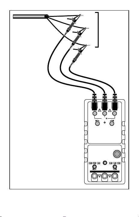
3-Phase Rotation Test
Caution
This instrument only indicates that voltage is present, not the
voltage level. Verify the actual voltage with a multimeter. Using the
wrong voltage can damage a motor.
Connect the three color coded test leads to the 3-phase input 1.
terminals, L1-L2-L3 also know as A-B-C or R-S-T. See Figure 1.
Connect the three color coded alligator clips to the terminals of 2.
a 3-phase power source. The connection order is optional. Use
extreme caution in this high voltage situation.
Confirm that all three lights below the test lead inputs on the 3.
PRM-4 are ON. If one or more of the three lights is OFF, there is an
open phase condition. Correct the power source problems before
proceeding (See Open Phase Test later in this manual). If the Open
Phase tests are good, the PRM-4 is defective. Repair or replace the
PRM-4 before proceeding.
If all three lamps are ON, check the phase rotation indication for 4.
the rotation direction, clockwise () or counter-clockwise ()
indicator.
If the counter clockwise lamp is ON, reverse the connections of any 5.
two of the three alligator clips for clockwise rotation. Use extreme
caution in this high voltage situation.
The phase sequence is correct for clockwise (6. ) rotation when
the clockwise lamp is ON and the power source terminals are
connected by the alligator clips to L1, L2, and L3. Remove power
and label the power source wires.
Open Phase Test
Caution
The multimeter used for this test should be properly rated for the
circuit under test.
Connect a multimeter (set to VAC and the voltage range expected) 1.
V input to the phase wire in question and the COM input to
neutral or ground to check the phase voltage. Use extreme
caution in this high voltage situation.
Verify that the two other phases are working properly and that 2.
the 3-phase to phase voltages are correct. If a problem is found,

8
correct the problem before returning to the 3-phase rotation test.
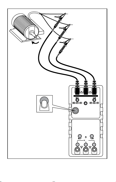
Motor Rotation Test
This test can be used to verify the shaft rotation and the M1-M2-M3
connections or to determine the M1-M2-M3 connections on a motor
that is not marked.
Warning
Make all connections with circuits unpowered. If the clockwise or
counterclockwise RED indicator is ON before rotating the motor
shaft, voltage is present. Stop measuring. Remove the test leads and
turn off the external power.
Use a multimeter to verify that no voltage is present on the motor 1.
windings.
Connect the color coded test leads to the three motor input 2.
terminals M1- M2-M3. Press the power button (See Figure 2). The
green indicator light will be ON.
Facing the motor shaft, hand rotate the motor shaft clockwise.3.
If the clockwise indicator (4. ) is ON, the M1-M2-M3 connections
are correct for clockwise rotation.
If the counterclockwise (5. ) indicator is ON, the M1-M2-M3
connections are correct for counterclockwise rotation.
If the motor rotation direction is wrong, reverse any two of the 6.
M1-M2-M3 connections and repeat the test.
After 3-phase rotation and motor phasing are verified:
Turn off power at the source.1.
Connect the previously identified power wire L1 to motor wire 2.
M1. Repeat the connections for L2 to M2 and L3 to M3. See Figure
3.
Inspect the connections for electrical safety.3.
The motor will rotate in the desired direction when power is
applied.
MAINTENANCE
If the PRM-4 appears to operate incorrectly, check the following
items:
Review the operating instructions to ensure the meter is being 1.

9
used correctly.
Inspect and test the continuity of the test leads.2.
Make sure the battery is in good condition. Replace a low battery 3.
immediately.
Check the condition of the fuses.4.
WARNING
To avoid electrical shock, remove the test leads from the PRM-4 and
the test circuit before accessing the battery or the fuse.
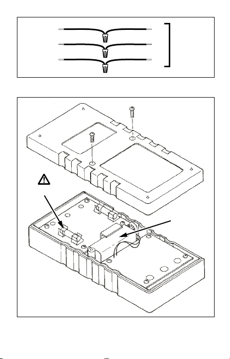
Battery and Fuse Replacement
To access these parts, you must first remove the rear cover of
the PRM-4. The rear cover is held in place with two screws. After
removing the screws, you can easily remove and replace the battery
or a fuse. To replace a fuse, pry it from the retaining clips using a
small screwdriver. See Figure 4.
Use the following replacement parts:
Battery: 9 V NEDA 1604, IEC 6F22
Phase Sequence Fuse: Fast Blow 200 mA/600 V (Amprobe FP900)
Motor Rotation Fuse: Fast Blow 100 mA/250 V (Littel Fuse 216.100)
Cleaning and Storage
Periodically wipe the case with a damp cloth and detergent. Do not
use abrasives or solvents. Remove the battery if the tester is not in use
for periods longer than 60 days.
SPECIFICATIONS
General Specifications
Operating Environment: 0 °C to 40 °C at <80 % R.H.
Power: Single standard 9 V battery, NEDA 1604, JIS 006P, IEC 6F22
Battery life: Approximately 200 hours typical with carbon-zinc battery
Low battery indication: The BATT LED does not come ON when TEST
button is pressed
Dimensions: 153(L) x 72(W) x 35(D) mm. (6.02 x 2.83 x 1.37 in)
Weight: Approximately 218 g (7 oz) including battery
Environment: Indoor use
Altitude: 2000 m (6561 ft.)

10
Overload protection: 600 V ac
Accessories: Test leads (TL-PRM-4) with alligator clips, two sets of
color coded clips, carrying case, Users Manual, battery
Agency Approvals
Safety: Conforms to EN61010-1:2001; CAT III 600V, Pollution degree 2,
Class 2; CSA 22.2 -1010-1, and EN61557-7
EMC: Conforms to EN61326-1. This product complies with
requirements of the following European Community Directives:
89/ 336/ EEC (Electromagnetic Compatibility) and 73/ 23/ EEC
(Low Voltage) as amended by 93/ 68/ EEC (CE Marking). However,
electrical noise or intense electromagnetic fields in the vicinity of
the equipment may disturb the measurement circuit. Measuring
instruments will also respond to unwanted signals that may be
present within the measurement circuit. Users should exercise care
and take appropriate precautions to avoid misleading results when
making measurements in the presence of electronic interference.
Electrical Specifications
Phase Sequence
Input Voltage: 3 phase to phase inputs - 100 V ac to 600 V ac max.
Frequency: 45 to 70 Hz
Operating time: 10 minutes ON maximum at 600 V ac. 10 minutes OFF
minimum at 600 V ac.
3-Phase load: Approx. 7 mA per phase of ac power source
Motor Rotation
Operating time: 10 minutes ON maximum. 10 minutes OFF minimum.
Motor Rotation tester field: 14 mA of 9 V battery
11
M1
M2
BATT
TEST
M3
L1
ABC
L2 L3
MOTOR ROTATION DETERMINED WHILE F ACING MOTOR SHAFT
CAT
600V
MOTOR
RO TATION
TESTER
3-PHASE
TESTER
PRM-4
PRM-4
DO NOT CONNECT TO LIVE VOLTAGE!
L1
3Ø
115 VAC to
600 VAC
L2
L3
Figure 1
12
M1
M2
BATT
TEST
M3
L1
A B C
L2 L3
MOTOR ROTATION DETERMINED WHILE FACING MOTOR SHAFT
CAT
600V
MOTOR
ROTATION
TESTER
3-PHASE
TESTER
PRM-4
PRM-4
DO NOT CONNECT TO LIVE VOLT AGE!
M1
M2
M3
Figure 2
13
Figure 4
M1
M2
M3
L1
L2
L3
3Ø
115 VAC to
600VAC
Figure 3
Fuse
9 V
Battery


15
Français
PRM-4
Contrôleur de rotation de
moteur et d’ordre de phases
Mode d’emploi
(French)

16
Limitation de garantie et de responsabilité
Amprobe garantit l’absence de vices de matériaux et de fabrication de ce produit dans des
conditions normales d’utilisation et d’entretien pendant une période d’un an prenant effet
à la date d’achat. Cette garantie ne s’applique pas aux fusibles, aux piles jetables ni à tout
produit mal utilisé, modifié, contaminé, négligé ou endommagé par accident ou soumis
à des conditions anormales d’utilisation et de manipulation. Les distributeurs agréés par
Amprobe ne sont pas autorisés à appliquer une garantie plus étendue au nom de Amprobe.
Pour bénéficier de la garantie, renvoyez le produit accompagné d’un justificatif d’achat
auprès d’un centre de services agréé par Amprobe Test ou du distributeur ou du revendeur
Amprobe. Voir la section Réparation ci-dessus pour tous les détails. LA PRESENTE GARANTIE
EST LE SEUL ET EXCLUSIF RECOURS TOUTES AUTRES GARANTIES, EXPLICITES, IMPLICITES OU
STATUTAIRES, NOTAMMENT LE CAS ECHEANT LES GARANTIES DE QUALITE MARCHANDE
OU D’ADAPTATION A UN OBJECTIF PARTICULIER SONT EXCLUES PAR LES PRESENTES. LE
FABRICANT NE SERA EN AUCUN CAS TENU RESPONSABLE DE DOMMAGES PARTICULIERS,
INDIRECTS, ACCIDENTELS OU CONSECUTIFS, NI D’AUCUNS DEGATS OU PERTES DE DONNEES,
SUR UNE BASE CONTRACTUELLE, EXTRA-CONTRACTUELLE OU AUTRE. Etant donné que
certains pays ou états n’admettent pas les limitations d’une condition de garantie implicite,
ou l’exclusion ou la limitation de dégâts accidentels ou consécutifs, les limitations et les
exclusions de cette garantie ne s’appliquent pas obligatoirement à chaque acheteur.
Réparation
Tous les appareils qui sont envoyés pour réparation ou calibrage dans le cadre de la garantie
ou en dehors de la garantie doivent être accompagnés de ce qui suit : Nom du client, nom
de la firme, adresse, numéro de téléphone et preuve d’achat. Prière de joindre en outre à
l’appareil de mesure une brève description du problème ou de la maintenance désirée ainsi
que les lignes de mesure. Les frais pour les réparations en dehors de la garantie ou pour
le remplacement d’instruments doivent être payés par chèque, virement bancaire, carte
de crédit (numéro de carte de crédit avec date d’expiration) ou une commande doit être
formulée au bénéfice de Amprobe Test Tools.
Réparations ou remplacement sous garantie — tous les pays. Veuillez lire la
déclaration de garantie subséquente et contrôler la pile avant de demander des réparations.
Pendant la période de garantie, tous les appareils défectueux peuvent être renvoyés à
un distributeur Amprobe Test Tools pour remplacement par un appareil identique ou un
produit similaire. Un répertoire des distributeurs agréés se trouve dans la section « Where to
Buy » (points de vente) sur le site web www.amprobe.com. De plus, aux USA et au Canada,
les appareils peuvent être envoyés à un centre de service après-vente Amprobe Test Tools
(adresse voir plus loin) pour réparation ou remplacement.
Réparations ou remplacement en dehors de la garantie - USA et Canada. Pour
les réparations en dehors de la garantie aux Etats-Unis et au Canada, les appareils sont
envoyés à un centre de service après-vente Amprobe Test Tools. Vous pouvez obtenir des
renseignements sur les prix de réparation et de remplacement actuellement en vigueur
auprès de Amprobe Test Tools ou du point de vente.
Aux USA : Au Canada :
Amprobe Test Tools Amprobe Test Tools
Everett, WA 98203 Mississauga, ON L4Z 1X9
Tél. : 877-993-5853 Tél. : 905-890-7600
Fax : 425-446-6390 Fax : 905-890-6866
Réparations ou remplacement en dehors de la garantie - Europe. Les appareils hors
garantie peuvent être remplacés contre paiement par le distributeur Amprobe Test Tools
compétent. Un répertoire des distributeurs agréés se trouve dans la section « Where to Buy »
(points de vente) sur le site web www.amprobe.com.
Adresse de correspondance pour l’Europe*
Amprobe Test Tools Europe
In den Engematten 14
79286 Glottertal, Germany
Tel.: +49 (0) 7684 8009 – 0
*(Uniquement correspondance — pas de réparations, pas de remplacement à cette adresse.
Les clients en Europe s’adressent au distributeur compétent.)

17
➊
Bornes d’entrée de rotation de phase
➋
Indicateurs de rupture de phase
➌
Indicateurs de rotation de phase
➍
Interrupteur marche/arrêt du vérificateur de moteur
➎
Témoin d’alimentation du vérificateur de moteur
➏
Indicateurs de rotation de moteur
➐
Bornes d’entrée de rotation de moteur
M1
M2
BATT
TEST
M3
L1
A B C
L2 L3
MOTOR ROTATION DETERMINED WHILE FACING MOTOR SHAFT
CAT
600V
MOTOR
ROTATION
TESTER
3-PHASE
TESTER
PRM-4
PRM-4
DO NOT CONNECT TO LIVE VOLTAGE!
1
4
6
3
5
2
7

18
PRM-4 Contrôleur de rotation de moteur et
d’ordre de phases
Consignes de sécurité .............................................................................19
Symboles utilisés dans ce mode d’emploi .............................................20
Introduction ............................................................................................20
Mesures ...................................................................................................21
Test de rotation triphasé .................................................................21
Test de rupture de phase .................................................................. 21
Test de rotation du moteur ..............................................................22
Entretien ................................................................................................. 23
Remplacement des fusibles et des piles ..........................................23
Nettoyage et stockage .....................................................................23
Caractéristiques ...................................................................................... 24
Caractéristiques générales ...............................................................24
Caractéristiques électriques .............................................................24

19
CONSIGNES DE SÉCURITÉ
Le contrôleur de rotation de moteur et de séquence de phase PRM-4
est conforme aux normes CSA 22.2-1010-1 et EN61010-1, CAT III 600 V.
Pour un fonctionnement et une utilisation sans danger de cet
appareil, suivez les instructions de ce mode d’emploi. Le non-respect
des mises en garde peut entraîner des blessures GRAVES, voire la
mort.
• Il est recommandé pour les installations fixes et au niveau
distribution, ainsi que pour les installations secondaires, mais non
pour les lignes d’alimentation primaires, les lignes aériennes et les
systèmes câblés.
• Ne pas dépasser les limites de surcharge maximum par fonction
(voir les caractéristiques techniques) ou les limites indiquées sur
l’appareil lui-même. Ne jamais appliquer plus de 600 V c.a. eff.
entre le cordon de mesure et la prise de terre.
• Inspecter le contrôleur, les cordons de mesure et les accessoires
avant chaque utilisation. Ne pas utiliser de pièce endommagée.
• Ne jamais se relier à la terre en prenant des mesures. Ne toucher ni
aux éléments de circuit exposés ni aux pointes des sondes de test.
• Ne pas utiliser l’appareil dans une atmosphère explosive.
• Faire preuve d’extrême prudence en : mesurant une tension >20
V // un courant >10 mA // les lignes d’alimentation secteur avec
charges inductives // les lignes d’alimentation secteur pendant les
orages électriques // un courant alors que le fusible a sauté dans
un circuit avec une tension en circuit ouvert > 600 V.
• Ne jamais installer un fusible de calibre différent.
• Retirer les cordons de mesure avant d’ouvrir le boîtier.
• Cet appareil doit être utilisé selon les conditions spécifiées afin de
ne pas entraver sa protection intrinsèque.

20
SYMBOLES UTILISÉS DANS CE MODE D’EMPLOI
Tension dangereuse
Courant alternatif
Se reporter au mode
d’emploi
Courant continu
Prise de terre
Association canadienne de
normalisation (CSA)
Double isolation
Conforme aux directives
de l’UE
INTRODUCTION
Le contrôleur propose trois fonctions dans un appareil compact,
notamment l’indication de rupture de phase, de succession des phases
et de rotation de moteur. Ce contrôleur est idéal pour l’installation
des tapis transporteurs, des systèmes de pompage et des commandes
interconnectées.
L’PRM-4 se compose de deux modules de mesure. L’un mesure l’ordre
des phases d’un système trifilaire en utilisant l’alimentation du
système testé. Il indique grâce à des témoins lumineux la séquence
triphasée ou une situation de rupture de phase. L’autre module de
l’PRM-4 mesure la rotation du moteur triphasé sur un moteur au
repos en utilisant la pile interne de 9 volts de l’PRM-4. L’appareil
indique alors si l’arbre moteur tourne dans le sens de rotation horaire
ou anti-horaire.
Fonctions :
Identifie la séquence triphasée et le contrôle de rupture de phase•
Rotation de l’arbre moteur•
Alimenté sur pile•
Conforme aux exigences EN61010 sur la sécurité•
Fourni avec trois grandes pinces crocodiles homologuées CAT III et •
des cordons de mesure repérés par couleur
Attention
Lire toutes les consignes de sécurité avant d’utiliser ce contrôleur.

21
MESURES
Test de rotation triphasé
Attention
Cet instrument indique uniquement la présence d’une tension, et
non pas son niveau. Vérifier la tension réelle à l’aide d’un multimètre.
L’utilisation d’une tension erronée peut endommager le moteur.
1. Branchez les trois cordons de mesure repérés par couleur aux
bornes d’entrées triphasées, L1 (rouge) - L2 (vert) - L3 (bleu) aussi
appelées A-B-C ou R-S-T. Voir Figure 1.
2. Branchez les trois pinces crocodiles repérées par couleur aux
bornes d’une source d’alimentation triphasée. L’ordre de
branchement est facultatif. Faire preuve d’extrême prudence dans
cette situation de tension élevée.
3. Confirmez que les trois témoins en dessous des entrées des
cordons de mesure sur l’PRM-4 sont allumés. L’extinction d’un
ou de plusieurs témoins signale une condition de rupture de
phase. Corrigez les problèmes de la source d’alimentation avant
de poursuivre (voir Test de rupture de phase dans la suite de ce
manuel). Si les tests de rupture de phase sont corrects, l’PRM-4 est
défectueux. Réparez ou remplacez l’PRM-4 avant de poursuivre.
4. Si les trois témoins sont allumés, vérifiez le sens de rotation en
consultant l’indicateur de rotation de phase : sens horaire ()
ou anti-horaire ().
5. Si le témoin de direction anti-horaire est allumé, inversez les
branchements de deux des trois pinces crocodiles pour obtenir une
rotation en sens horaire. Faire preuve d’extrême prudence dans
cette situation de tension élevée.
6. L’ordre des phases est correct en rotation horaire () lorsque
le témoin de rotation horaire est allumé et que les bornes de la
source d’alimentation sont connectées par les pinces crocodiles
ROUGE, VERT et BLEU en L1, L2 et L3. Coupez l’alimentation et
identifiez les fils de la source d’alimentation.
Test de rupture de phase
Attention
Le multimètre utilisé pour ce test doit être correctement homologué
pour le circuit testé.
1. Branchez l’entrée V d’un multimètre (réglé sur VAC et la gamme
de tension attendue) au fil de phase voulu, et l’entrée COM à
neutre ou à la terre pour vérifier la tension de phase. Faire preuve
d’extrême prudence dans cette situation de tension élevée.
2. Vérifiez si les deux autres phases fonctionnent correctement et si
les tensions triphasées à phase sont correctes. Si un problème est
 Loading...