


5XP-A
15XP-A
35XP-A
Compact
Digital
Multimeters
Users Manual
•Manual de uso
•Mode d'emploi
•Bedienungshandbuch
•Manuale d'Uso

RANGE  NON
NON
CONTACT
VOLTAGE
OFF
V V
|
|
A |
|
|
mA |
|
|
A |
HZ |
|
A |
|
|
mA |
400 |
|
A |
°C 1000 |
1832 °F |
400 |
|
auto-off |
1 |
2 |
5 |
3 |
4
6 |
35XP-A

5XP-A
15XP-A
35XP-A
Compact Digital Multimeters
Users Manual
•Manual de uso
•Mode d’emploi
•Bedienungshandbuch
•Manuale d’Uso
PN 2728995 July 2006
©2006, Amprobe Test Tools.
All rights reserved. Printed in Taiwan.

5XP-A
15XP-A
35XP-A
Compact Digital Multimeters
Users Manual
•Manual de uso
•Mode d’emploi
•Bedienungshandbuch
•Manuale d’Uso
English
PN 2728995 July 2006
©2006 Amprobe→ Test Tools.
All rights reserved. Printed in Taiwan.
Limited Warranty and Limitation of Liability
Your Amprobe→ product will be free from defects in material and workmanship for 1 year from the date of purchase. This warranty does not cover fuses, disposable batteries or damage from accident, neglect, misuse, alteration, contamination, or abnormal conditions of operation or handling. Resellers are not authorized to extend any other warranty on Amprobe→’s behalf. To obtain service during the warranty period, return the product with proof of purchase to an authorized Amprobe→ Test Tools Service Center or to a Amprobe→ dealer or distributor. See Repair Section above for details. THIS WARRANTY IS YOUR ONLY REMEDY. ALL OTHER WARRANTIES - WHETHER EXPRESS, IMPLIED OR STAUTORY - INCLUDING IMPLIED WARRANTIES OF FITNESS FOR A PARTICULAR PURPOSE OR MERCHANTABILITY, ARE HEREBY DISCLAIMED. MANUFACTURER SHALL NOT BE LIABLE FOR ANY SPECIAL, INDIRECT, INCIDENTAL OR CONSEQUENTIAL DAMAGES OR LOSSES, ARISING FROM ANY CAUSE OR THEORY. Since some states or countries do not allow the exclusion or limitation of an implied warranty or of incidental or consequential damages, this limitation of liability may not apply to you.

|
XP Series Digital Multimeters |
|||
Contents |
|
|
|
|
Safety Information .............................................................................................. |
|
|
|
2 |
Symbols Used in this Manual ............................................................................. |
|
|
|
3 |
Making Measurements........................................................................................ |
|
|
|
3 |
Verify Instrument Operation............................................................................. |
|
|
|
3 |
Range Selection ............................................................................................... |
|
|
|
3 |
Correcting an Overload (0o or -0o) Indication W............................................ |
3 |
|||
Measuring DC Voltage |
See Figure -1- ..................................................... |
3 |
||
Measuring AC Voltage |
See Figure -2- ..................................................... |
4 |
||
Preparing for Current Measurements............................................................... |
|
4 |
||
Measuring DC Current |
See Figure -3- ..................................................... |
4 |
||
Measuring AC Current |
See Figure -4- ..................................................... |
4 |
||
Measuring Resistance |
See Figure -5- ..................................................... |
5 |
||
Testing for Continuity |
See Figure -6- ..................................................... |
5 |
||
Testing Diodes |
See Figure -7- ..................................................... |
5 |
||
Measuring Capacitance (35XP-A only) |
See Figure -8- .................................. |
5 |
||
Measuring Temperature (35XP-A only) |
See Figure -9-................................. |
6 |
||
Measuring Frequency (35XP-A only) |
See Figure -10-................................... |
6 |
||
Measuring NCV (Non-Contact Voltage) |
See Figure -11- ........................... |
6 |
||
Testing Battery Voltage (5XP-A only) |
See Figure -12- .................................. |
6 |
||
Testing Logic Levels (15XP-A only) |
See Figure -13- .................................... |
7 |
||
Additional Features ............................................................................................. |
|
|
|
7 |
Input Test Lead Warning.................................................................................. |
|
|
|
7 |
MIN MAX Measurements (Model 5XP-A only)................................................. |
7 |
|||
Auto Power Off (Models 15XP-A and 35XP-A only)......................................... |
7 |
|||
HOLD Measurements....................................................................................... |
|
|
|
7 |
Product Maintenance .......................................................................................... |
|
|
|
8 |
Cleaning........................................................................................................... |
|
|
|
8 |
Troubleshooting............................................................................................... |
|
|
|
8 |
Battery and Fuse Replacement |
See Figure -14- ....................................... |
8 |
||
Repair ................................................................................................................. |
|
|
|
9 |
Specifications ................................................................................................... |
|
|
|
10 |
1
5XP-A |
15XP-A |
35XP-A |
|||||||
|
|
|
5XP-A |
|
|
15XP-A |
|
|
-A |
MIN MAX |
|
NON |
HOLD |
RANGE |
NON |
HOLD |
RANGE |
NON |
HOLD |
CONTACT |
CONTACT |
CONTACT |
|||||||
|
VOLTAGE |
|
|
VOLTAGE |
|
|
VOLTAGE |
|
|
|
750 |
OFF 1000 |
|
|
A |
|
|
OFF |
V |
200 |
|
200 |
|
|
|
mA |
|
V |
|
20 |
|
|
20 |
|
|
A |
|
|
A |
V 2 |
|
|
2 V |
|
|
|
|
|
mA |
200 |
|
|
200 |
|
|
A |
|
|
|
m |
|
|
m |
|
|
|
|
|
|
|
|
|
200 |
|
|
mA |
|
|
A |
|
|
|
|
|
|
|
|
||
20M |
|
|
2m |
|
|
|
|
|
|
2M |
|
|
20m |
V |
|
A |
HZ |
|
A |
200k |
|
|
200 |
|
|
|
|
|
|
|
|
m |
V |
|
|
|
|
mA |
|
20k |
|
|
200m |
|
|
|
|
|
|
2k |
|
9V 200 2m |
20m |
OFF |
|
|
400 |
|
A |
200 |
1.5V |
|
|
|
auto-off |
˚C |
1000 |
400 |
|
|
BATT |
A |
|
|
|
1832 ˚F |
auto-off |
||
Safety Information
•The XP Series Digital Multimeters conform to EN61010-1, Rev-2; CAT I 1000 V, CAT II 600 V, CAT III 300 V, class 2 and pollution deg.2; CSA 22.2 -1010-1.
•This instrument is EN61010-1 certified for Installation Category I (1000V). It may only be used to make measurements on energy limited circuits within equipment and not directly connected to mains.
•This instrument is EN61010-1 certified for Installation Category II (600 V). It is recommended for use with local level power distribution, appliances, portable equipment, etc, where only smaller transient overvoltages may occur, and not for primary supply lines, overhead lines and cable systems.
•This instrument is EN61010-1 certified for Installation Category III ( 300 V). It is recommended for use in distribution level and fixed installations, as well as lesser installations, and not for primary supply lines, overhead lines and cable systems.
•Do not exceed the maximum overload limits per function (see specifications) nor the limits marked on the instrument itself. Never apply more than 1000 V dc/750 V ac rms between the test lead and earth ground.
•Inspect the DMM, test leads and accessories before every use. Do not use any damaged part.
•Never ground yourself when taking measurements. Do not touch exposed circuit elements or test probe tips.
•Do not operate the instrument in an explosive atmosphere.
•Exercise extreme caution when: measuring voltage >20 V // current >10 mA // AC power line with inductive loads // AC power line during electrical storms // current, when the fuse blows in a circuit with open circuit voltage >1000 V // servicing CRT equipment.
•Always measure current in series with the load – NEVER ACROSS a voltage source. Check fuse first. Never replace a fuse with one of a different rating.
•Remove test leads before opening the case.
2

Symbols Used in this Manual
|
B |
Battery |
W |
Refer to the manual |
|
T |
Double insulated |
X |
Dangerous Voltage |
|
F |
Direct Current |
J |
Earth Ground |
|
B |
Alternating Current |
R |
Audible tone |
|
I |
Fuse |
) |
Canadian Standards Association |
|
|
|
|
|
|
P |
Complies with EU |
z |
Non-contact Voltage |
|
directives |
|
|
|
|
|
|
|
|
|
|
|
|
|
Making Measurements
Verify Instrument Operation
Before attempting to make a measurement, verify that the instrument is operational and the battery is good. If the instrument is not operational, have it repaired before attempting to make a measurement.
Range Selection
In addition to autoranging (Models 15XP-A and 35XP-A only) you can manually select and lock a range by pressing the RANGE button. RANGE appears on the display to indicate that manual ranging is active and the range is locked. When appropriate, each subsequent press of the range button steps the meter to the next higher range. When the highest range is reached the next press returns the meter to the lowest range. To return to autoranging press the RANGE button. If RANGE still shows on the display, autoranging is not available for the selected function. Use autorange for all initial measurements. Then, when appropriate, use the RANGE button to select and lock a range.
XWWarning
To avoid electrical shock while manual ranging, use the display annunciators to identify the actual range selected.
Correcting an Overload (0o or -0o) Indication W
An 0o or -0o indication may appear on the display to indicate that an overload condition exists. For voltage and current measurements, an overload should be immediately corrected by selecting a higher range. If the highest range setting does not eliminate the overload, interrupt the measurement until the problem is identified and eliminated. The 0o indication is normal for some functions; for example, resistance, continuity, and diode test.
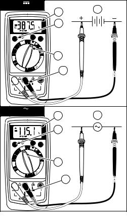
Measuring DC Voltage |
See Figure -1- |
1.Set the Function Switch to v.
2.Select the desired RANGE. The default DC voltage range is 2 V on the 15XP-A and 4 V on the 35XP-A.
3.Connect the test leads: Red to E, Black to COM.
4.Connect the test probes to the circuit test points.
5.Read the display, and, if necessary, correct any overload (0o) conditions.
3
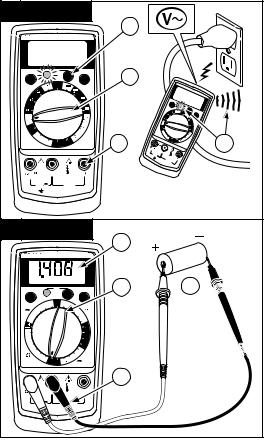
Measuring AC Voltage |
See Figure |
-2- |
1.Set the Function Switch to V.
2.Select the desired RANGE. The default AC voltage range is 2 V on the 15XP-A and 4 V on the 35XP-A.
3.Connect the test leads: Red to E, Black to COM.
4.Connect the test probes to the circuit test points.
5.Read the display, and, if necessary, correct any overload (0o) conditions.
Preparing for Current Measurements
•Turn off circuit power before connecting the test probes.
•Allow the meter to cool between measurements, if current measurements approach or exceeds 2 amps.
•A warning tone sounds if you connect a test lead to a current input while a current function is not selected.
•Open circuit voltage at the measurement point must not exceed 1000 V.
•Always measure current in series with the load. Never measure current across a voltage source.
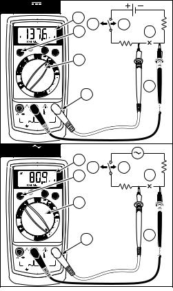
Measuring DC Current |
See Figure |
-3- |
1.Set the Function Switch to a current function, µA, mA, or A.
2.Select the desired RANGE (5XP-A only).
3.Connect the test leads: Red to mA or A, Black to COM.
4.Turn off power to the circuit being measured.
5.Open the test circuit (X) to establish measurement points.
6.Connect the test probes in series with the load (to the measurement points).
7.Turn on power to the circuit being measured.
8.Read the display, and, if necessary, correct any overload (0o or -0o) conditions.
Measuring AC Current |
See Figure |
-4- |
1.Set the Function Switch to a current function and range, µA, mA, or A.
2.Select the desired RANGE (5XP-A only).
3.Connect the test leads: Red to mA or A, Black to COM.
4.Turn off power to the circuit being measured.
5.Open the test circuit (X) to establish measurement points.
6.Connect the test probes in series with the load (to the measurement points).
7.Turn on power to the circuit being measured.
8.Read the display, and, if necessary, correct any overload (0o) conditions.
4
Measuring Resistance |
See Figure -5- |
1.Set the Function Switch to Ω.
2.Select the desired RANGE (5XP-A, 15XP-A).
3.Connect the test leads: Red to E, Black to COM.
4.Turn off power to the circuit being measured. Never measure resistance across a voltage source or on a powered circuit.
5.Discharge any capacitors that may influence the reading.
6.Connect the test probes across the resistance.
7.Read the display. If 0o appears on the highest range, the resistance is too large to be measured or the circuit is an open circuit.
8.(15XP-A) The 2000 MΩ range has a fixed 10-count offset in the reading. For example, when measuring 1100 MΩ, the display reads 1110. The 10 residual must be subtracted to obtain the actual value of 1100 MΩ
Testing for Continuity |
See Figure -6- |
1.Set the Function Switch to R.
2.Connect the test leads: Red to E, Black to COM.
3.Turn off power to the circuit being measured.
4.Discharge any capacitors that may influence the reading.
5.Connect the test probes across the resistance or the two points of test.
6.Listen for the tone that indicates continuity (< 40 Ω).
Testing Diodes |
See Figure |
-7- |
1.Set the Function Switch to G.
2.Connect the test leads: Red to E, Black to COM.
3.Turn off power to the circuit being measured.
4.Free at least one end of the diode from the circuit.
5.Connect the test probes across the diode.
6.Read the display. A good diode has a forward voltage drop of about 0.6 V. An open or reverse biased diode will read 0o.
Measuring Capacitance (35XP-A only) |
See Figure |
-8- |
1.Set the Function Switch to the P function.
2.Connect the test leads: Red to h, Black to COM.
4.Turn off power to the circuit being measured.
5.Discharge the capacitor using a 100 kΩ resistor.
6.Free at least one end of the capacitor from the circuit.
7.Connect the test probes across the capacitor.
8.Read the display.
5

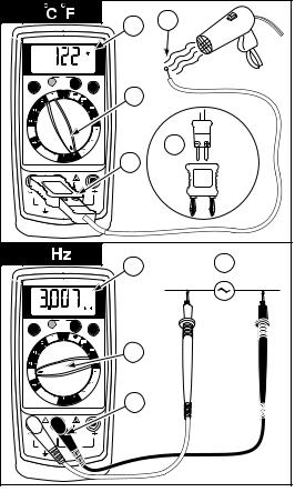
Measuring Temperature (35XP-A only) |
See Figure |
-9- |
1.Set the function switch to appropriate °C or °F range.
2.Connect the K-type thermocouple to a TEMP adapter (XR-TA). Match the polarity of the adapter to the polarity of the thermocouple.
3.Connect the TEMP adapter to the E and COM inputs.
Note: The 35XP-A is compatible with all K-type thermocouples. The K-type bead thermocouple supplied with the meter is not intended for contact with liquids or electrical circuits.
4.Expose the thermocouple to the temperature to be measured.
5.Read the display.
Measuring Frequency (35XP-A only) |
See Figure |
-10- |
1.Set the Function Switch to Hz.
2.Connect the test leads: Red to Hz, Black to COM.
3.Connect the test probes to the signal source.
4.Read the display.
Measuring NCV (Non-Contact Voltage) See Figure -11-
1.Range switch may be set to OFF or any function/range.
2.Test leads are not used for the NCV test.
3.Press the NCV button. The display goes blank, a tone sounds and the red LED next to the NCV button on the front panel lights up to verify that the instrument is operational. While pressing the button, hold the top-center of the meter z (sensor location) close to the conductor/circuit in question.
4.If a voltage in the range of 70 to 600 V ac is present, a tone sounds and the red LED next to the NCV button on the front panel lights up.
Testing Battery Voltage (5XP-A only) |
See Figure |
-12- |
1.Set the Function Switch to the appropriate BATT setting, 1.5 V or 9 V.
2.Connect the test leads: Red to BATT 1.5 V or BATT 9 V, Black to COM.
3.Connect the test probes across the battery. The meter applies an appropriate load to the battery.
4.Read the display. A good 1.5 volt battery should measure >1.2 V, and a good 9 volt battery should measure > 7.2 V.
6

Testing Logic Levels (15XP-A only) |
See Figure -13- |
The 15XP-A tests logic levels for TTL logic. The meter displays 0o plus a for a high-level (true) condition. The meter beeps and displays an 0o and a for a low-level (false) condition. See Specifications for the logic 1 and logic 0 voltage limits. Out-of-limits indications are displayed as 0o only, no , or beep occur.
1.Set the Function Switch to LOGIC.
2.Connect the test leads: Red to E, Black to COM.
3.Connect the black lead to logic common.
4.Connect the red lead to the logic test point.
5.Read the display.
Additional Features
Input Test Lead Warning
The meter emits a continuous tone when a test lead is placed in the mA or A input jack and the Function/Range Switch is not set to a correct current position. (If the meter is connected to a voltage source with leads connected for current, very high current could result). All current ranges are protected by fast acting fuses.
MIN MAX Measurements (Model 5XP-A only)
The MIN MAX feature reads and updates the display to show the maximum or minimum value measured after you press the MIN MAX button.
Pressing the MIN MAX button for less than 1 second will put the meter into a mode of displaying the maximum or minimum readings. Each time the button is pressed, the meter will cycle to the next display mode. Press the MIN MAX button for more than 1 second to disable this feature.
Auto Power Off (Models 15XP-A and 35XP-A only)
Auto Power Off is a battery saving feature that puts the meter into a sleep mode if the Function/Range Switch has not changed position in the last 10 minutes. To wake the meter turn the Function/Range Switch to another position.
The Auto Power Off feature can be disabled to keep the meter from going to sleep. To disable the Auto Power Off feature use the following procedure:
1.Set the Function Switch to OFF.
2.Press and hold the Range button while turning the Function Switch from OFF to the desired function.
3.Release the Range button. The Auto Power Off feature will remain disabled until the meter is turned off and then on.
HOLD Measurements
The HOLD button causes the meter to capture and continuously display a measurement reading. To use the HOLD feature make a measurement, and then, after the reading has stabilized, momentarily press the HOLD button. You can remove the test leads and the reading will remain on the display. Pressing the HOLD button again releases the display.
7

Product Maintenance
Cleaning
To clean the meter, use a soft cloth moistened with water. To avoid damage to the plastic components do not use benzene, alcohol, acetone, ether, paint thinner, lacquer thinner, ketone or other solvents to clean the meter.
Troubleshooting
If the meter appears to operate improperly, check the following items first.
1.Review the operating instructions to ensure the meter is being used properly.
2.Inspect and test the continuity of the test leads.
3.Make sure the battery is in good condition. The low battery symbol M appears when the battery falls below the level where accuracy is guaranteed. Replace a low-battery immediately.
4.Check the condition of the fuses if the current ranges operate incorrectly.
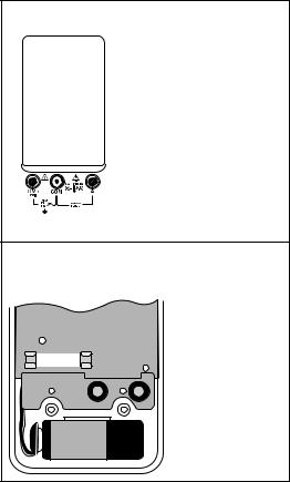
Battery and Fuse Replacement |
See Figure -14- |
XWWARNING
To avoid electrical, shock remove the test leads from both the meter and the test circuit before accessing the battery or the fuses.
To replace the fuse:
1.Remove the 2 rear-case screws.
2.Separate the case.
3.Remove and replace the 2 A fuse (15XP-A or 35XP-A) or 0.315 fuse (5XP-A).
4.Reassemble the meter.
Fuse:
Fast Blow 2 A/1000 V, minimum interrupt rating 30 kA (6 x 32 mm) (Amprobe→ FP200).
Fast Blow 0.315 A/1000 V minimum interrupt rating 30 kA (6.3 x 32 mm) (Amprobe→ FP300)
8

AC CURRENT (45 Hz to 500 Hz) Ranges: 200 µA, 2 mA, 20 mA, 200 mA,
± (2.0 % rdg + 5 dgts)
RESISTANCE
Ranges: 200 Ω, 2 kΩ, 20 kΩ, 200 kΩ, 2 MΩ, 20 MΩ
Accuracy: ± (1.0 % rdg + 4 dgts) on 200 to 200 kΩ ranges: ± (1.5 % rdg + 4 dgts) on 2 MΩ range: ± (3.0 % rdg + 5 dgts) on 20 MΩ range
CONTINUITY
Audible indication: 75 ± 25 Ω
DIODE TEST
Test current: 1.0 mA (approximate) Accuracy: ± (1.5 % rdg + 3 dgts) Open circuit volts: 3.0 dc typical
BATTERY TEST
Ranges: 1.5 V, 9 V
Accuracy: ± (3.5 % rdg + 2 dgts)
OVERLOAD PROTECTION
Voltage, Resistance, Diode, Continuity: 1000 VDC or 750 VAC rms
200 mV Range: 1000 VDC / 750 VAC rms (3 minutes)
Current: 0.315 A / 1000 V fast blow ceramic fuse 6.3 × 32 mm
mA JACK: Input warning detects wrong switch/input jack configuration
AUXILIARY FEATURES
DATA HOLD: Freeze the latest reading on the display.
MIN/MAX: Record the maximum and minimum reading in a measurement.
15XP-A Electrical Specifications
(at 23°C ± 5°C, < 75 % R.H.)
DC VOLTS
Ranges: 200 mV, 2 V, 20 V, 200 V, 1000 V
Accuracy: ±(0.5 % rdg + 1 dgt) AC VOLTS (45 Hz to 500 Hz)
Ranges: 200 mV, 2 V, 20 V, 200 V, 750 V
Accuracy: ±(1.5 % rdg + 5 dgts) 45 Hz to 100 Hz on 200 mV range ±(1.5 % rdg + 5 dgts) on 2 V to 750 V ranges
DC CURRENT
Ranges: 200 µA, 2000 µA, 20 mA, 200 mA, 2 A
Accuracy: ±(1.0 % rdg + 2 dgts) on 200 µA to 200 mA ranges: ±(2.0 % rdg + 3 dgts) on 2 A range
AC CURRENT (45 Hz to 500 Hz)
Ranges: 200 µA, 2000 µA, 20 mA, 200 mA, 2 A
Accuracy: ±(1.5 % rdg + 5 dgts) on 200 µA to 200 mA ranges: ±(2.5 % rdg + 5 dgts) on 2 A range
RESISTANCE
Ranges: 200 Ω, 2 kΩ, 20 kΩ, 200 kΩ, 2 MΩ, 20 MΩ, 2000 MΩ
Accuracy: ± (1.0 % rdg + 4 dgts) on 200 to 2 MΩ ranges: ± (3.0 % rdg + 5 dgts) on 20 MΩ range
± {5.0 % (rdg -10 dgt) + 20 dgt} on 2000 MΩ range
CONTINUITY
Audible indication: Less than 25 Ω
DIODE TEST
Test current: 1.2 mA (approximate) Accuracy: ±(1.5 % rdg + 3 dgts) Open circuit volts: 3.0 dc typical
LOGIC TEST
Thresholds Logic 1 (Hi): 2.8 V ± 0.8 V Thresholds Logic o (Lo): 0.8 V ± 0.5 V Test voltage: TTL 5 VDC
OVERLOAD PROTECTION
Voltage, Resistance, Diode, Continuity, Logic: 1000 VDC or 750 VAC rms
Current: 2 A / 1000 V fast blow ceramic fuse 6.3 × 32 mm
mA JACK: Input warning detects wrong switch / input jack configuration
AUXILIARY FEATURES
DATA HOLD: Freeze the latest reading on the display.
RANGE: Execute manual range mode.
AUTO Power off: After auto power off, press (RANGE) button to restart the meter, and the last reading of measurement will be returned to the display.
11

35XP-A Electrical Specifications
(at 23°C ± 5°C, < 75 % R.H.)
DC VOLTS
Ranges: 400 mV, 4 V, 40 V, 400 V, 1000 V
Accuracy: ± (0.5 % rdg + 1 dgt) AC VOLTS (45 Hz to 500 Hz)
Ranges:400 mV, 4 V, 40 V, 400 V, 750 V
Accuracy: ± (1.5 % rdg + 5 dgts) 45 Hz to 100 Hz on 400 mV range: ± (1.5 % rdg + 5 dgts) on 4 V to 750 V ranges
DC CURRENT
Ranges: 400 µA, 4000 µA, 40 mA, 400 mA, 2 A
Accuracy: ± (1.0 % rdg + 2 dgts) on 400 µA to 400 mA ranges: ± (2.0 % rdg + 3 dgts) on 2 A range
AC CURRENT (45 Hz to 500 Hz)
Ranges: 400 µA, 4000 µA, 40 mA, 400 mA, 2A
Accuracy: ± (1.5 % rdg + 5 dgts) on 400 µA to 400 mA ranges: ± (2.5 % rdg + 5 dgts) on 2 A range
RESISTANCE
Ranges: 400 Ω, 4 kΩ, 40 kΩ, 400 kΩ, 4 MΩ, 40 MΩ
Accuracy: ± (1.0 % rdg + 4 dgts) on 400 to 4 MΩ ranges: ± (3.0 % rdg + 5 dgts) on 40 MΩ range
CONTINUITY
Audible indication: Less than 25 Ω
DIODE TEST
Test current: 1.2 mA (approximate) Accuracy: ±(1.5 % rdg + 3 dgts) Open circuit volts: 3.0 dc typical
CAPACITANCE
Ranges: 4 nF, 40 nF, 400 nF, 4 µF, 40 µF, 400 µF, 4 mF
Accuracy: ± (5.0 % rdg + 30 dgts) on 4 nF range: ± (5.0 % rdg + 5 dgts) on 40 nF and 400 µF ranges: ± (5.0 % rdg + 15 dgts) on 4 mF range
TEMPERATURE
Ranges: -20°C to 1000°C, -4°F to 1832°F
Accuracy: ± (2.0 % rdg +4°C) -20°C to 10°C
±(1.0 % rdg + 3°C)10°C to 200°C
±(3.0 % rdg + 2°C) 200°C to 1000°C
±(2.0 % rdg + 8°F) -4°F to 50°F
±(1.0 % rdg + 6°F) 50°F to 400°F
±(3.0 % rdg + 4°F) 400°F to1832°F
FREQUENCY
Ranges: 4 k, 40 k, 400 k, 1 MHz Accuracy: ± (0.1 % rdg + 3 dgts) Sensitivity:
10 Hz to 1 MHz: >2.5 V rms
OVERLOAD PROTECTION
Voltage, Resistance, Diode, Continuity, Frequency, Temperature: 1000 VDC or 750 VAC rms
Current, Capacitance: 2 A / 1000 V fast blow ceramic fuse 6.3 × 32 mm
mA JACK: Input warning detects wrong switch/input jack configuration
AUXILIARY FEATURES
DATA HOLD: Freeze the latest reading on the display.
RANGE: Execute manual range mode.
AUTO Power off: After auto power off, press (RANGE) button to restart the meter, and the last reading of measurement will be returned to the display.
12
1 |
V |
5 |
4 |
|
|
|
|
|
|
35XP-A |
|
|
|
2 |
|
NON
RANGE CONTACT HOLD
VOLTAGE
OFF
V V
A
mA
A
HZ |
A |
1 |
|
|
|
|
|
mA |
|
˚C |
|
|
|
|
A |
3 |
1000 |
1832 |
˚F |
400 |
auto-off |
2 |
V |
5 |
4 |
|
|
||
|
|
35XP-A |
|
|
|
2 |
|
NON
RANGE CONTACT HOLD
VOLTAGE
V |
OFF |
|
V |
A |
|
|
|
|
|
|
mA |
|
|
A |
HZ |
|
A |
|
|
mA |
400 |
|
A |
˚C 1000 |
1832 ˚F 400 |
auto-off |
1 |
3 |
13
3 |
A |
35XP-A
8 |
|
4 |
7 |
2 |
5 |
NON
RANGE CONTACT HOLD
VOLTAGE
OFF
V V
A
mA
1 |
A
HZ |
A |
|
|
|
|
|
mA |
6 |
˚C |
|
|
|
|
A |
3 |
1000 |
1832 |
˚F |
400 |
auto-off |
4 |
A |
8 |
|
|
|
|
|
|
35XP-A |
4 |
7 |
|
|
2 |
5 |
RANGE |
NON |
HOLD |
CONTACT |
||
|
VOLTAGE |
|
|
OFF |
|
V V
A
|
mA |
|
A |
HZ |
A |
|
mA |
˚C 1000 1832 ˚F 400 |
A |
auto-off |
1 |
6
3
14
5 |
|
|
|
|
|
7 |
|
|
|
|
|
|
|
5 |
|
|
|
|
|
|
|
|
|
|
|
|
|
|
35XP-A |
|
4 |
|
|
|
|
|
|
|
|
|
|
|
|
|
|
2 |
|
RANGE |
|
NON |
|
|
HOLD |
|
|
|
CONTACT |
|
|
|
|
||
|
|
VOLTAGE |
|
|
|
|
|
|
V |
OFF |
|
V |
|
1 |
6 |
|
|
|
A |
||||
|
|
|
|
|
|
||
|
|
|
|
|
mA |
|
|
|
|
|
|
|
A |
|
|
HZ |
|
|
|
|
A |
|
|
|
|
|
|
|
mA |
|
|
˚C |
|
|
|
|
A |
|
|
1000 |
1832 |
˚F |
400 |
auto-off |
3 |
|
|
|
|
|
|
||||
|
|
|
|
|
|
|
|
6 |
|
|
|
|
|
|
|
|
|
|
|
|
35XP-A |
|
|
RANGE |
|
NON |
|
|
HOLD |
|
5 |
|
CONTACT |
|
|
|
|||
|
|
VOLTAGE |
|
|
|
|
|
|
|
|
|
|
|
|
|
|
V |
OFF |
|
V |
|
|
|
|
|
|
A |
|
|
||
|
|
|
|
|
|
|
|
|
|
|
|
|
mA |
|
|
|
|
|
|
|
A |
|
|
HZ |
|
|
|
|
A |
1 |
|
|
|
|
|
|
mA |
3 |
|
400 |
|
|
|
|
A |
|
|
˚C |
1000 |
1832 |
˚F |
400 |
auto-off |
|
|
|
|
|
|
|
|
2 |
4 |
|
|
|
|
|
|
|
6 |
|
|
|
|
|
|
|
15 |

7 |
|
|
|
|
|
6 |
3 |
|
|
|
|
|
|
|
|
|
|
|
|
|
35XP-A |
|
4 |
|
|
|
|
|
|
|
|
RANGE |
|
NON |
|
|
HOLD |
1 |
|
|
CONTACT |
|
|
|
|||
|
|
VOLTAGE |
|
|
|
|
|
|
|
|
|
|
|
|
|
|
V |
OFF |
|
V |
|
|
|
|
|
|
A |
|
|
||
|
|
|
|
|
|
|
|
|
|
|
|
|
mA |
|
|
|
|
|
|
|
A |
|
|
HZ |
|
|
|
|
A |
|
|
|
|
|
|
|
mA |
|
|
˚C |
|
|
|
|
A |
2 |
|
1000 |
1832 |
˚F |
400 |
auto-off |
|
||
8 |
|
|
|
|
|
7 |
|
|
|
|
|
|
|
|
|
|
|
|
|
|
35XP-A |
|
|
RANGE |
|
NON |
|
|
HOLD |
|
|
|
CONTACT |
|
|
|
|
||
|
|
VOLTAGE |
|
|
|
1 |
6 |
|
V |
OFF |
|
V |
|
||
|
|
|
A |
|
|
||
|
|
|
|
|
|
|
|
|
|
|
|
|
mA |
|
|
|
|
|
|
|
A |
|
|
HZ |
|
|
|
|
A |
|
|
|
|
|
|
|
mA |
|
3 |
400 |
|
|
|
|
A |
|
|
˚C |
1000 |
1832 |
˚F |
400 |
auto-off |
|
|
|
|
|
|
|
|||
|
|
|
|
|
|
2 |
4 |
|
|
|
|
|
|
|
|
|
|
|
|
|
|
|
5 |
|
|
|
|
|
|
16 |
|
9 |
|
|
|
|
|
5 |
4 |
|
|
|
|
|
|
|
|
|
|
|
|
|
|
|
35XP-A |
|
|
|
RANGE |
|
NON |
|
|
HOLD |
|
|
|
|
CONTACT |
|
|
|
|
|
||
|
|
VOLTAGE |
|
|
|
|
|
|
|
V |
OFF |
|
V |
|
1 |
|
|
|
|
|
A |
|
|
|||
|
|
|
|
|
|
|
||
|
|
|
|
|
mA |
|
|
|
|
|
|
|
|
A |
|
|
|
HZ |
|
|
|
|
A |
|
|
K |
|
|
|
|
|
mA |
|
2 |
|
|
|
|
|
|
|
|
|
|
˚C |
|
|
|
|
A |
|
|
|
1000 |
1832 |
˚F |
400 |
auto-off |
3 |
|
|
|
|
|
|
|
|
||||
|
|
|
|
|
|
|
|
|
10 |
|
|
|
|
|
4 |
|
3 |
|
|
|
|
|
|
|
||
|
|
|
|
|
|
|
|
|
|
|
|
|
|
35XP-A |
|
|
|
RANGE |
|
NON |
|
|
HOLD |
|
|
|
|
CONTACT |
|
|
|
|
|
||
|
|
VOLTAGE |
|
|
|
|
|
|
|
V |
OFF |
|
V |
|
|
|
|
|
|
|
A |
|
|
|
||
|
|
|
|
|
|
|
|
|
|
|
|
|
|
mA |
1 |
|
|
|
|
|
|
|
|
|
|
|
|
|
|
|
|
A |
|
|
|
HZ |
|
|
|
|
A |
|
|
|
|
|
|
|
|
mA |
|
|
|
400 |
|
|
|
|
A |
2 |
|
|
˚C |
1000 |
1832 |
˚F |
400 |
auto-off |
|
|
|
|
|
|
|
|
|
|
17 |
|
11 |
NCV |
|
|
3 |
|
|
|
|
||||
|
|
|
|
|
|
|
|
|
|
|
|
|
|
|
|
|
|
|
35XP-A |
|
|
|
|
|
|
RANGE |
|
|
|
|
|
HOLD |
|
1 |
|
|
|
|
|
|
|
|
|
|
|
|
|
|
|
|
|
|
V |
|
OFF |
|
V |
|
|
|
|
|
|
|
|
|
|
|
A |
|
|
|
|
|
|
||
|
|
|
|
|
|
|
|
|
|
|
|
|
|
|
|
|
|
|
mA |
|
|
|
|
|
35XP-A |
|
|
|
|
|
|
|
RANGE |
|
|
|
||
|
|
|
|
|
|
|
|
|
|
|
||
|
|
|
|
|
|
A |
|
|
V |
OFF |
|
HOLD |
|
|
|
|
|
|
|
|
|
|
|||
|
|
|
|
|
|
|
|
|
|
|
V |
|
HZ |
|
|
|
|
|
A |
|
HZ |
|
|
A |
|
|
|
|
|
|
|
|
|
|
|
mA |
|
|
|
|
|
|
|
|
|
|
|
|
|
|
|
|
|
|
|
|
|
mA |
|
|
|
|
2A |
|
|
|
|
|
|
|
|
|
400 |
|
|
2A |
|
400 |
|
|
|
|
|
|
|
˚C |
|
|
|
|
|
|
|
|
|
A |
2 |
1000 |
|
m |
A |
4 |
|
˚C |
1000 1832 |
˚F 400 |
1832 |
˚F 400 |
A |
|||||||
|
auto-off |
|
|
auto-off |
||||||||
12 |
BATT |
|
4 |
|
|
|
|
|
||||
|
|
|
|
|
|
|
|
|
|
|
|
|
|
|
|
|
|
|
5XP-A |
|
|
|
|
|
|
MIN MAX |
|
|
NON |
|
|
HOLD |
1 |
|
|
|
3 |
|
|
CONTACT |
|
|
|
|
|
|
|||||
|
|
VOLTAGE |
|
|
|
|
|
|
|
|
|
|
|
200 |
750 |
OFF 1000 |
200 |
|
|
|
|
|
|
|
|
20 |
|
|
|
|
|
20 |
|
|
|
|
|
|
V 2 |
|
|
|
|
|
2 V |
|
|
|
|
|
|
200 |
|
|
|
|
|
200 |
|
|
|
|
|
|
m |
|
|
|
|
|
m |
|
|
|
|
|
|
|
|
|
|
|
|
200 |
|
|
|
|
|
|
20M |
|
|
|
|
|
2m |
|
|
|
|
|
|
2M |
|
|
|
|
|
20m |
|
|
|
|
|
|
200k |
|
|
|
|
|
200 |
|
|
|
|
|
|
|
|
|
|
|
m |
|
|
|
|
|
|
|
20k |
|
|
|
|
|
200m |
|
|
|
|
|
|
2k |
|
|
|
|
|
20m |
|
|
|
|
|
|
|
200 |
1.5V |
9V |
200 |
2m |
A |
|
|
|
|
|
|
|
|
BATT |
|
|
|
|
|
|
|
|
||
|
|
|
|
|
|
|
|
|
|
|
|
|
|
|
|
|
|
|
|
2 |
|
|
|
|
|
|
|
|
|
|
|
|
|
18 |
|
|
|
|
15XP-A |
(15XP-A/35XP-A) |
(5XP-A) |
19 |
20
 Loading...