


DM-5
Power Quality Analyzer
Manual
DM-5
 Logging

DM-5
Power Quality Analyzer
Instruction Manual
English
11/2015, 6006992 Rev A ©2015 Amprobe.
All rights reserved.
Limited Warranty and Limitation of Liability
Your Amprobe product will be free from defects in material and workmanship for 1 year from the date of purchase. This warranty does not cover fuses, disposable batteries or damage from accident, neglect, misuse, alteration, contamination, or abnormal conditions of operation or handling. Resellers are not authorized to extend any other warranty on Amprobe’s behalf.
To obtain service during the warranty period, return the product with proof of purchase to an authorized Amprobe Test Tools Service Center or to an Amprobe dealer or distributor. See Repair Section for details. THIS WARRANTY IS YOUR ONLY REMEDY. ALL OTHER WARRANTIES - WHETHER EXPRESS, IMPLIED OR STAUTORY - INCLUDING IMPLIED WARRANTIES OF
FITNESS FOR A PARTICULAR PURPOSE OR MERCHANTABILITY, ARE HEREBY DISCLAIMED. MANUFACTURER SHALL NOT BE LIABLE FOR ANY SPECIAL, INDIRECT, INCIDENTAL OR CONSEQUENTIAL DAMAGES OR LOSSES, ARISING FROM ANY CAUSE OR THEORY. Since some states or countries do not allow the exclusion or limitation of an implied warranty or of incidental or consequential damages, this limitation of liability may not apply to you.
Repair
All Amprobe tools returned for warranty or non-warranty repair or for calibration should be accompanied by the following: your name, company’s name, address, telephone number, and proof of purchase. Additionally, please include a brief description of the problem or the service requested and include the test leads with the meter. Non-warranty repair or replacement charges should be remitted in the form of a check, a money order, credit card with expiration date, or a purchase order made payable to Amprobe.
In-warranty Repairs and Replacement – All Countries
Please read the warranty statement and check your battery before requesting repair. During the warranty period, any defective test tool can be returned to your Amprobe distributor for an exchange for the same or like product. Please check the “Where to Buy” section on www.Amprobe.com for a list of distributors near you. Additionally, in the United States and Canada, in-warranty repair and replacement units can also be sent to an Amprobe Service Center (see address below).
Non-warranty Repairs and Replacement – United States and Canada
Non-warranty repairs in the United States and Canada should be sent to an Amprobe Service Center. Call Amprobe or inquire at your point of purchase for current repair and replacement rates.
USA: |
Canada: |
Amprobe |
Amprobe |
Everett, WA 98203 |
Mississauga, ON L4Z 1X9 |
Tel: 888-993-5853 |
Tel: 905-890-7600 |
Fax: 425-446-6390 |
Fax: 905-890-6866 |
Non-warranty Repairs and Replacement – Europe
European non-warranty units can be replaced by your Amprobe distributor for a nominal charge. Please check the “Where to Buy” section on www.Amprobe.eu for a list of distributors near you.
Amprobe Europe* Beha-Amprobe
In den Engematten 14 79286 Glottertal, Germany Tel.: +49 (0) 7684 8009 - 0 www.Amprobe.eu
*(Correspondence only – no repair or replacement available from this address. European customers please contact your distributor.)

|
DM-5 Power Quality Analyzer |
|
CONTENTS |
|
|
SAFETY WARNINGS................................................................................................... |
4 |
|
UNPACKING AND INSPECTION.................................................................................. |
8 |
|
1 INSTRUMENT OVERVIEW ...................................................................................... |
9 |
|
1.1 |
Functional overview........................................................................................................ |
9 |
1.2 |
Features........................................................................................................................... |
12 |
1.3 |
Constructional drawing.................................................................................................. |
14 |
1.4 |
Steps for measurement................................................................................................... |
15 |
2 INSTRUMENT LAYOUT............................................................................................ |
16 |
|
2.1 |
Display (LCD)/ Keys.......................................................................................................... |
16 |
2.2 |
Connector........................................................................................................................ |
17 |
2.3 |
Side face.......................................................................................................................... |
18 |
2.4 |
Voltage test lead and clamp sensor............................................................................... |
19 |
3 BASIC OPERATIONS................................................................................................ |
20 |
|
3.1 |
Key Operation................................................................................................................. |
20 |
3.2 |
Icons On The Lcd............................................................................................................. |
21 |
3.3 |
Symbols On The Lcd........................................................................................................ |
22 |
3.4 |
Backlight And Contrast Adjustment.............................................................................. |
22 |
3.5 |
Screens............................................................................................................................. |
23 |
|
Inst/ Integration/ Demand.............................................................................................. |
23 |
|
Vector............................................................................................................................... |
24 |
|
Waveform........................................................................................................................ |
25 |
|
Harmonic Analysis........................................................................................................... |
26 |
|
Power Quality.................................................................................................................. |
27 |
|
Settings............................................................................................................................ |
27 |
4 GETTING STARTED.................................................................................................. |
28 |
|
4.1 |
Power Supply................................................................................................................... |
28 |
|
Battery............................................................................................................................ |
28 |
|
Battery symbol on the LCD/ Battery level...................................................................... |
29 |
|
How to install batteries.................................................................................................. |
30 |
|
Power cord connection................................................................................................... |
30 |
|
Power supply rating........................................................................................................ |
31 |
4.2 |
Placing / removing SD card............................................................................................. |
32 |
|
Inserting SD card............................................................................................................. |
32 |
|
Removing SD card........................................................................................................... |
32 |
4.3 |
Voltage test leads and clamp sensor connection.......................................................... |
33 |
4.4 |
Start DM-5....................................................................................................................... |
34 |
|
Start-up screen................................................................................................................ |
34 |
|
Cautionary message........................................................................................................ |
34 |
1

|
DM-5 Power Quality Analyzer |
|
4.5 |
Recording procedures..................................................................................................... |
35 |
|
Start of recording............................................................................................................ |
35 |
|
End of recording............................................................................................................. |
35 |
|
Start measurement with “Quick Start Guide” ............................................................. |
36 |
5 SETTINGS................................................................................................................. |
44 |
|
5.1 |
List of setting items......................................................................................................... |
44 |
5.2 |
Basic setting..................................................................................................................... |
44 |
|
Settings of wiring system............................................................................................... |
45 |
|
Wiring connection.......................................................................................................... |
46 |
|
Settings of voltage measurement.................................................................................. |
48 |
|
VT/CT................................................................................................................................ |
49 |
|
Settings of current measurement.................................................................................. |
50 |
|
Settings of external input terminal/ reference frequency............................................ |
52 |
5.3 |
Measurement setting...................................................................................................... |
53 |
|
Settings of demand measurement................................................................................. |
53 |
|
Outline of demand measurement concept................................................................... |
55 |
|
Settings for harmonic analysis....................................................................................... |
56 |
|
Threshold setting for power quality (Event)................................................................. |
57 |
|
Filter setting for flicker measurement........................................................................... |
61 |
|
Target power factor for capacitance calculation.......................................................... |
62 |
5.4 |
Recording setting............................................................................................................ |
62 |
|
Settings for recording items........................................................................................... |
63 |
|
Saved items...................................................................................................................... |
64 |
|
Recording method.......................................................................................................... |
65 |
|
Possible recording time.................................................................................................. |
66 |
5.5 |
Other settings.................................................................................................................. |
67 |
|
Settings for system environment................................................................................... |
67 |
|
DM-5 Setting................................................................................................................... |
68 |
5.6 |
Saved data....................................................................................................................... |
71 |
|
Delete, transfer or format the recorded data............................................................... |
71 |
|
Type of the saved data.................................................................................................... |
72 |
|
DM-5 settings and Data loading.................................................................................... |
78 |
6 DISPLAYED ITEMS................................................................................................... |
81 |
|
6.1 |
Instantaneous value “W”............................................................................................... |
81 |
|
List display of the measured values............................................................................... |
81 |
|
Zoom display................................................................................................................... |
84 |
|
Displaying trend graph................................................................................................... |
85 |
|
Changing displayed items and display position............................................................ |
86 |
6.2 |
Integration value “Wh”.................................................................................................. |
87 |
2

|
DM-5 Power Quality Analyzer |
|
6.3 |
Demand........................................................................................................................... |
88 |
|
Showing the measured values....................................................................................... |
88 |
|
Shifts in specific period................................................................................................... |
89 |
|
Demand change.............................................................................................................. |
90 |
6.4 |
Vector............................................................................................................................... |
91 |
6.5 |
Waveform........................................................................................................................ |
93 |
6.6 |
Harmonics........................................................................................................................ |
94 |
|
Displaying harmonics on the bar graph........................................................................ |
95 |
|
Displaying the list of harmonics..................................................................................... |
96 |
6.7 |
Power quality.................................................................................................................. |
99 |
|
Factors impair power quality and symptoms................................................................ |
99 |
|
Displaying recorded events............................................................................................ |
101 |
|
Displaying measured flicker values in list form............................................................. |
104 |
|
Displaying trend graph of Pst, 1min.............................................................................. |
105 |
|
Displaying changes of Plt............................................................................................... |
106 |
7 OTHER FUNCTIONS................................................................................................. |
107 |
|
8 DEVICE CONNECTION............................................................................................. |
109 |
|
8.1 |
Data transfer to PC......................................................................................................... |
109 |
8.2 |
Using wireless function................................................................................................... |
109 |
8.3 |
Signal control.................................................................................................................. |
110 |
|
Connection to input/ output terminals.......................................................................... |
110 |
8.4 |
Getting power from measured lines.............................................................................. |
112 |
9 PC SOFTWARE FOR SETTING AND DATA ANALYSIS............................................. |
113 |
|
10 SPECIFICATION...................................................................................................... |
114 |
|
10.1 Safety requirements...................................................................................................... |
114 |
|
10.2 General specification.................................................................................................... |
114 |
|
10.3 Measurement specification.......................................................................................... |
117 |
|
|
Measured items and the number of analysis points..................................................... |
117 |
|
Items measured at Instantaneous measurement.......................................................... |
118 |
|
Items to be calculated..................................................................................................... |
121 |
|
Items measured at integration measurement............................................................... |
124 |
|
Items measured at demand measurement.................................................................... |
127 |
|
Items measured at harmonics measurement................................................................ |
128 |
|
Items measured at power quality measurement.......................................................... |
133 |
10.4 Specification of clamp sensor....................................................................................... |
136 |
|
11 TROUBLESHOOTING............................................................................................................................................. |
138 |
|
11.1 General troubleshooting.............................................................................................. |
138 |
|
11.2 Error messages and actions.......................................................................................... |
139 |
|
3

Safety warnings
This instrument has been designed, manufactured and tested according to IEC 61010-1: Safety requirements for Electronic Measuring apparatus, and delivered in the best condition after passing quality control tests.
This instruction manual contains warnings and safety procedures which have to be observed by the user to ensure safe operation of the instrument and to maintain it in safe condition. Therefore, read through these operating instructions before starting to use the instrument.
WARNING
-About Instruction manual -
•Read through and understand the instructions contained in this manual before using the instrument.
•Keep the manual at hand to enable quick reference whenever necessary.
•The instrument is to be used only in its intended applications.
•Understand and follow all the safety instructions contained in the manual.
•Read the enclosed Quick Start Guide after reading this instruction manual.
•For all accessories and attachments, refer to the individual instruction manual supplied when applicable.
It is essential that the above instructions are adhered to. Failure to follow the above instructions may cause injury, instrument damage and/or damage to equipment under test. Amprobe assumes no responsibility for damage and injury caused by misuse or not following the instructions in the manual.
The symbol Windicated on the instrument, means that the user must refer to the related parts in the manual for safe operation of the instrument. It is essential to read the instructions wherever the symbol appears in the manual.
DANGER : is reserved for conditions and actions that are likely to cause serious or fatal injury.WARNING : is reserved for conditions and actions that can cause serious or fatal injury.CAUTION : is reserved for conditions and actions that can cause injury or instrument damage.
Measurement Category
To ensure safe operation of measuring instruments, IEC 61010 establishes safety standards for various electrical environments, categorized as O to CAT.IV, and called measurement categories. Higher-numbered categories correspond to electrical environments with greater momentary energy, so a measuring instrument designed for CAT.III environments can endure greater momentary energy than one designed for CAT.II.
O : Circuits which are not directly connected to the mains power supply.
CAT.II : Electrical circuits of equipment connected to an AC electrical outlet by a power cord.
CAT.III : Primary electrical circuits of the equipment connected directly to the distribution panel, and feeders from the distribution panel to outlets.
CAT.IV : The circuit from the service drop to the service entrance, and to the power meter and primary overcurrent protection device (distribution panel).
4

Safety warnings
DANGER
•The instrument is to be used only in its intended applications or conditions. Otherwise, safety functions equipped with the instrument will not work, and instrument damage or serious personal injury may occur. Verify proper operation on a known source before taking action as a result of the indication of the instrument.
•With attention to the measurement category to which the object under test belongs, do not make measurements on a circuit in which the electrical potential exceeds the following values. * 300V AC for CAT. IV, 600V AC for CAT. III, 1000V AC for CAT. II
•Do not attempt to make measurement in the presence of flammable gasses.
Otherwise, the use of the instrument may cause sparking, which can lead to an explosion.
•Never attempt to use the instrument if its surface or your hand is wet.
Measurement
•Do not exceed the maximum allowable input of any measuring range.
•Never open the battery compartment cover during a measurement.
Battery
•Do not try to replace batteries during a measurement.
•Brand and type of the batteries to be used should be harmonized.
Power cord
•Connect the power cord to an outlet.
•Use only the power cord supplied with this instrument.
Power supply connector
•Never touch the power supply connector although it is insulated while the instrument is operating with batteries.
Voltage test leads
•Use only the ones supplied with this instrument.
•Choose and use the test leads and caps that are suitable for the measurement category.
•When the instrument and the test lead are combined and used together, whichever lower category either of them belongs to will be applied. Confirm that the measured voltage rating of the test lead is not exceeded.
5

Safety warnings
•Do not connect a voltage test lead unless required for measuring the desired parameters.
•Connect voltage test leads to the instrument first, and only then connect them to the circuit under test.
•Keep your fingers behind the barrier during a measurement. Barrier: provides protection against electrical shock and ensuring the minimum required air and creepage distances.
•Never disconnect the voltage test leads from the connectors of the instrument during a measurement (while the instrument is energized).
•Do not touch two lines under test with the metal tips of the test leads.
•Never touch the metal tips of the test leads.
Clamp sensor
•Use only the ones dedicated for this instrument.
•Confirm that the measured current rating of the test lead and the maximum rated voltage are not exceeded.
•Do not connect a clamp sensor unless required for measuring the desired parameters.
•Connect sensors to the instrument first, and only then connect them to the circuit under test.
•Keep your fingers behind the barrier during a measurement. Barrier: provides protection against electrical shock and ensuring the minimum required air and creepage distances.
•Never disconnect sensors from the connectors of the instrument while the instrument is in use.
•Connect to the downstream side of a circuit breaker since a current capacity at the upstream side is larger.
•Do not touch two lines under test with the metal tips of the test leads.
CAUTION
•Caution should be taken since conductors under test may be hot.
•Never apply currents or voltages exceeding the maximum allowable input for the instrument for a long time.
•Do not apply currents or voltages for the clamp sensors or voltage test leads while the instrument is off.
•Don’t use the instrument in dirty or dusty environments.
•Don’t use the instrument under a strong electric storm or in the vicinity of energized object.
•Never give strong vibrations or drop shocks.
•Insert an SD card to the slot with the top side turned up. If the card is inserted up- side-down, the SD card or the instrument may be damaged.
• While using an SD card, do not replace or remove the card. (The |
symbol blinks |
while accessing SD card.) Otherwise, the saved data in the card may be lost or the instrument may be damaged.
6
Safety warnings
Clamp sensor
• Do not bend or pull the cable of the clamp sensor.
Treatment after use
•Power off the instrument and disconnect the power cord, voltage test leads and clamp sensors from the instrument.
•Remove the batteries if the instrument is to be stored and will not be in use for a long period.
•Remove the SD card when carrying the instrument.
•Never give strong vibrations or drop shocks when carrying the instrument.
•Do not expose the instrument to direct sunlight, high temperatures, humidity or dew.
•Use a damp cloth with neutral detergent or water for cleaning the instrument. Do not use abrasives or solvents.
•Do not store the instrument if it is wet.
Carefully read and follow the instructions: DANGER, WARNING, CAUTION and NOTE ( ) described in each section.
Meaning of symbols on the instrument:
W |
Caution! Refer to the explanation in this Manual. |
T |
The equipment is protected by double insulation or reinforced |
insulation. |
|
B |
Alternating Current (AC). |
J |
Earth (Ground). |
7

UNPACKING AND INSPECTION
Your shipping carton should include: 1 DM-5 power quality meter
1CT-53 flex AC current clamp
1CT-500 flex AC current clamp
4 Test lead with alligator clip (red/black/blue/green)
1 US power cord
1 SD card (2G)
1 USB cable
32 Cable tie (8 colors)
6 AA batteries
1 User manual
1 PC Software (CD ROM)
1 Carrying case
If any of the items are damaged or missing, return the complete package to the place of purchase for an exchange.
The included printed manual is a simplified version of the full instruction manual which can be found on the supplied CD-ROM. This manual is intended only as a handy reference guide and should only be used after having read the full instruction manual which contains full details on each function of this instrument and the items contained in the package.
8

1. Instrument overview
1.1 Functional overview
Start/ Stop
Choose either “Quick start guide” or “Start now” to start recording. Perform simple and fast start-up setting by selecting “Quick start guide”.
See “Start/Stop Recording” for further details.
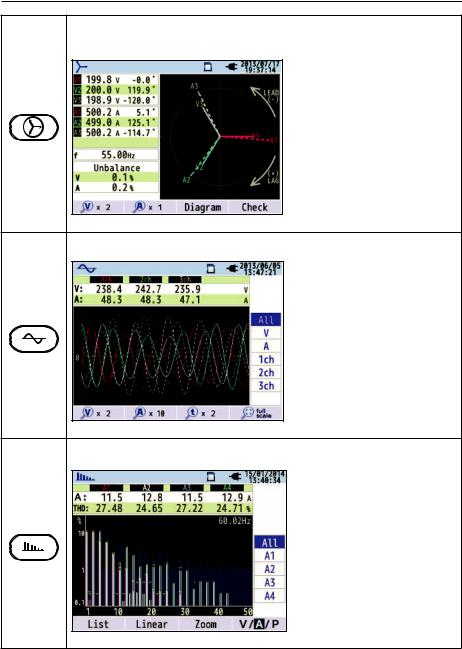
Inst/ Integration/ Demand
Display the avg/ max/ min instantaneous values of current/ voltage/ active power/ apparent power/ reactive power. Integration values also can be viewed by switching screens. Moreover, demand values with the preset target value can also be checked.
See “Inst/ Integration/ Demand” for further details.
9
1. Instrument overview
Vector and Wiring Check
Vectors of voltage and current per CH are displayed on a graph. DM-5 will perform wiring check.
See “Vector” for further details.
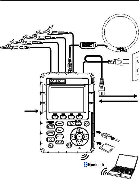
Waveform
Waveforms of voltage and current per CH are displayed on a graph.
See “Waveform” for further details.
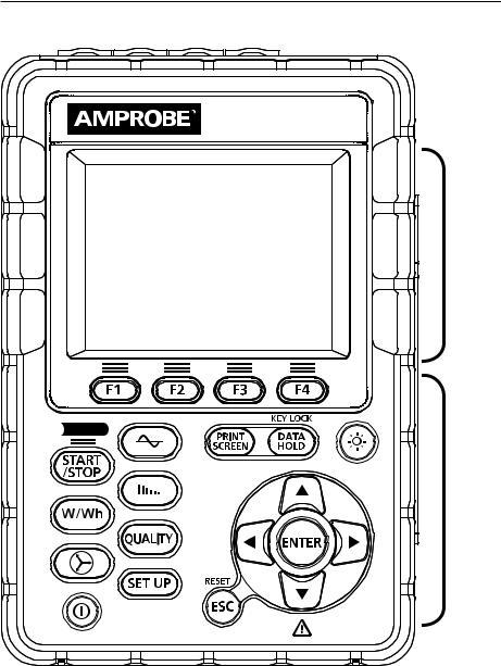
Harmonic Analysis
Harmonic components of voltage and current per CH are displayed on a graph.
See “Harmonic Analysis” for further details.
10

1. Instrument overview
Power Quality (QUALITY) event
Display voltage swell, dip, int, transient, inrush currentand flicker.
See “Power Quality” for further details.
Setting (SET UP)
Make settings for DM-5 and measurements.
See “Setting” for further details.
11

1. Instrument overview
1.2 Features
This is a clamp-type power quality analyzer that can be used for various wiring systems. It can be used for simple measurements of instantaneous/ integration/ demand values, and also for analysis of harmonics and events related to power quality and for the simulation of power factor correction with capacitor banks. It can display waveforms and vectors of
voltage and current. Data can be saved either on the SD card or in the internal memory, and can be transferred to a PC via USB, or in real-time via wireless connectivity with a compatible Bluetooth® enabled device.
Safety construction
Designed to meet the international safety standard IEC 61010-1 CAT.IV 300V/ CAT.III 600V/ CAT.II 1000V.
Power quality analysis
DM-5 is designed to meet the international standard IEC61000-4-30 Class S and can measure frequency and r.m.s. voltage with high accuracy, and also can analyze harmonics.
Moreover, it can measure swell, dip, interruption, transient, inrush current and flicker, gapless, all at once.
Power measurement
DM-5 measures active/reactive/apparent power, electrical energy, power factor, r.m.s. current, phase angle and neutral current simultaneously.
Wiring configuration
DM-5 supports: Single-phase 2-wire (4-system), Single-phase 3-wire (2-system), Threephase 3-wire (2-system) and Three-phase 4-wire.
Demand measurement
Electricity consumption can be easily monitored so as not to exceed the target maximum demand values.
Waveform/ vector display
Voltage and current can be displayed by waveform or vector.
Saving data
The DM-5 features a logging function with preset recording intervals. Data can be saved by manual operation or by specifying date and time. A screenshot of the data on the screen can be saved by using the Print Screen function.
Dual power supply system
DM-5 operates either with AC power supply or with batteries. Size AA alkaline dry-cell batteries and size AA Ni-MH rechargeable batteries can both be used. To charge size AA Ni-MH rechargeable batteries, use the charger which is manufactured by the same company as the batteries. In the event of power interruption, while operating with AC power supply, power to the instrument is automatically restored by the batteries in the instrument.
Large display
TFT color display with large screen.
12

1. Instrument overview
Compact design
Compact power quality analyzer.
Application
Data in the SD card or the internal memory can be saved in PC via USB. Analysis of the downloaded data and instrument settings are possible by using the special software “Windows for DM-5”.
Real-time communication with compatible devices is available via wireless connectivity to Bluetooth® enabled devices.
Input/ Output function
Analog signals from thermometers or light sensors can be measured simultaneously with electrical power data via 2 analog inputs (DC voltage); when any events related to power quality occur, signals can be transmitted to alarm devices via one digital output.
13
1. Instrument overview
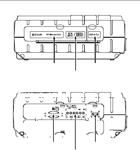
1.3 Constructional drawing
Current input
AC voltage input
Power cord
Size AA alkaline |
|
dry-cell battery (LR6) |
Logging |
or Size AA Ni-MH |
|
rechargeable battery |
|
DM-5
Digital output (1 ch) to recorder or alarm
Analog input (2 ch) from thermometer or illuminometer
USB
PC
SD card
14

1. Instrument overview
1.4 Steps for measurement
Read through the operating instructions described in “Safety warnings” (P.8) before starting to use the instrument.
Preparation
Chap. 4: Getting started (P.28)
Cord and Sensor Connection
Clause 4.3: Voltage test leads and clamp sensor connection (P.33)
Turning on the Instrument.
Clause 4.4: Start DM-5 (P.34)
Basic Settings. |
Reading the Setup Data |
Clause 5.2: Basic setting (P.44) |
Clause 5.6: Saved data (P.71) |
|
|
Wiring
Clause 5.2: Basic setting – Wiring (P.44)
Wiring Check
Clause 6.4: Vector (P.91)
Advanced Setting and Data Save Method
Clause 5.3: Measurement setting (P.53) / 5.4: Recording setting (P.62)
Confirming the Measured Values.
Clause 6.1: Inst value [W] (P.81) / 6.4: Vector (P.91)
Start/ Stop Recording
Clause 4.5: Recording procedures (P.35)
Confirming the Measured Data.
Chap. 6: Displayed items (P.81)
Disconnect the cords and sensors from the measurement line, and turn off the instrument.
Data Analysis on PC
Clause 8.1: Data transfer to PC (P.109)
Chap. 9: PC software for setting and data analysis (P.113)
15
2. Instrument layout
2.1 Display (LCD)/ Keys
DM-5
Display
(LCD)
 Logging
Keys
16
2. Instrument layout
2.2 Connector
AC voltage input terminal (VN, V1, V2, V3)
Current clamp input terminal (A1, A2, A3, A4)


 Terminal cover Power connector
Wiring configuration |
|
AC Voltage Input |
Current Input |
|
Terminal |
Terminal* |
|
|
|
||
|
|
|
|
Single-phase 2-wire (1-system) |
1P2W×1 |
VN, V1 |
A1 |
|
|
|
|
Single-phase 2-wire (2-system) |
1P2W×2 |
VN, V1 |
A1, A2 |
|
|
|
|
Single-phase 2-wire (3-system) |
1P2W×3 |
VN, V1 |
A1, A2, A3 |
|
|
|
|
Single-phase 2-wire (4-system) |
1P2W×4 |
VN, V1 |
A1, A2, A3, A4 |
|
|
|
|
Single-phase 3-wire (1-system) |
1P3W×1 |
VN, V1, V2 |
A1, A2 |
|
|
|
|
Single-phase 3-wire (2-system) |
1P3W×2 |
VN, V1, V2 |
A1, A2, A3, A4 |
|
|
|
|
Three-phase 3-wire (1-system) |
3P3W×1 |
VN, V1, V2 |
A1, A2 |
|
|
|
|
Three-phase 3-wire (2-system) |
3P3W×2 |
VN, V1, V2 |
A1, A2, A3, A4 |
|
|
|
|
Three-phase 3-wire 3A |
3P3W3A |
V1, V2, V3 |
A1, A2, A3 |
|
|
|
|
Three-phase 4-wire |
3P4W×1 |
VN, V1, V2, V3 |
A1, A2, A3 |
|
|
|
|
* Measurements of r.m.s. values and harmonics are possible at the Current terminals, which are not used for wiring connection.
17
2. Instrument layout
2.3 Side face
When the connector cover is closed.
SD slot cover |
USB port cover |
Analog output / Digital output cover
When the connector cover is opened.
|
|
|
|
|
|
|
|
|
|
|
|
|
|
|
|
|
|
|
|
|
|
|
|
|
|
|
|
|
|
|
|
|
|
|
|
|
|
|
|
|
|
|
|
|
|
|
|
|
|
|
|
|
|
|
|
|
|
|
|
|
|
|
|
|
|
|
|
|
|
|
|
|
|
|
|
|
|
|
|
|
|
|
|
|
|
|
|
|
|
|
|
|
|
|
|
|
|
|
|
|
|
|
|
|
|
|
|
|
|
|
|
|
|
|
|
|
|
|
|
|
|
|
|
|
|
|
|
|
|
|
|
|
|
|
|
|
|
|
|
|
|
|
|
|
|
|
|
|
|
|
|
|
|
|
|
|
|
|
|
|
|
|
|
|
|
|
|
|
|
|
|
|
|
|
|
|
|
|
|
|
|
|
|
|
|
|
|
|
|
|
|
|
|
|
|
|
|
|
|
|
|
|
|
|
|
|
|
|
|
|
|
|
|
|
|
|
|
|
|
|
|
|
|
|
|
|
|
|
|
|
|
|
|
|
|
|
|
|
|
|
|
|
|
|
|
|
|
|
|
|
|
|
|
|
|
|
|
|
|
|
|
|
|
|
|
|
|
|
|
|
|
|
|
|
|
|
|
|
|
|
|
|
|
|
|
|
|
|
|
|
|
|
|
|
|
|
|
|
|
|
|
|
|
|
|
|
|
|
|
|
|
|
|
|
|
|
|
|
|
|
|
|
|
|
|
|
|
|
|
|
|
|
|
|
|
|
|
|
|
|
|
|
|
|
|
|
|
|
|
|
|
|
|
|
|
|
|
|
|
|
|
|
|
|
|
|
|
|
|
|
|
|
|
|
|
|
|
|
|
|
|
|
|
|
|
|
|
|
|
|
|
|
|
|
|
|
|
|
|
|
|
|
|
|
|
|
|
|
|
|
|
|
|
|
|
|
|
|
|
|
|
|
|
|
|
|
|
|
|
|
|
|
|
|
|
|
|
|
|
|
|
|
|
|
|
|
|
|
|
|
|
|
|
|
|
|
|
|
|
|
|
|
|
|
|
|
|
|
|
|
|
|
|
|
|
|
|
|
|
|
|
|
|
|
|
|
|
|
|
|
|
|
|
|
|
|
|
|
|
|
|
|
|
|
|
|
|
|
|
|
|
|
|
|
|
|
|
|
|
|
|
|
|
|
|
|
|
|
|
|
|
|
|
|
|
|
|
|
|
|
|
|
|
|
|
|
|
|
|
|
|
|
|
|
|
|
|
|
|
|
|
|
|
|
|
|
|
|
|
|
|
|
|
|
|
|
|
|
|
|
|
|
|
|
|
|
|
|
|
|
|
|
|
|
|
|
|
|
|
|
|
|
|
|
|
|
|
|
|
|
|
|
|
|
|
|
|
|
|
|
|
|
|
|
|
|
|
|
|
|
|
|
|
|
|
|
|
|
|
|
|
|
|
|
|
|
|
|
|
|
|
|
|
|
|
|
|
|
|
|
|
|
|
|
|
|
|
|
|
|
|
|
|
|
|
|
|
|
|
|
|
|
|
|
|
|
|
|
|
|
|
|
|
|
|
|
|
|
|
|
|
|
|
|
|
|
|
|
|
|
|
|
|
|
|
|
|
|
|
|
|
|
|
|
|
|
|
|
|
|
|
|
|
|
|
|
|
|
|
|
|
|
|
|
|
|
|
|
|
|
|
|
|
|
|
|
|
|
|
|
|
|
|
|
|
|
|
|
|
|
|
|
|
|
|
|
|
|
|
|
|
|
|
|
|
|
|
|
|
|
|
|
|
|
|
|
|
|
|
|
|
|
|
|
|
|
|
|
|
|
|
|
|
|
|
|
|
|
|
|
|
|
|
|
|
|
|
|
|
|
|
|
|
|
|
|
|
|
|
|
|
|
|
|
|
|
|
|
|
|
|
|
|
|
|
|
|
|
|
|
|
|
|
|
|
|
|
|
|
|
|
|
|
|
|
|
|
|
|
|
|
|
|
|
|
|
|
|
|
|
|
|
|
|
|
|
|
|
|
|
|
|
|
|
|
|
|
|
|
|
|
|
|
|
|
|
|
|
|
|
|
|
|
|
|
|
|
|
|
|
|
|
|
|
|
|
|
|
|
|
|
|
|
|
|
|
|
|
|
|
|
|
|
|
|
|
|
|
|
|
|
|
|
|
|
|
|
|
|
|
|
|
|
|
|
|
|
|
|
|
|
|
|
|
|
|
|
|
|
|
|
|
|
|
|
|
|
|
|
|
|
|
|
|
|
|
|
|
|
|
|
|
|
|
|
|
|
|
|
|
|
|
|
|
|
|
|
|
|
|
|
|
|
|
|
|
|
|
|
|
|
|
|
|
|
|
|
|
|
|
|
|
|
|
|
|
|
|
|
|
|
|
SD card slot |
USB port |
|
|
|
|
|
|
||||||||||||||||||||||||||||||||||||||||||||||||||||||
|
|
|
|
|
|
|
|
|
|
|
|
|
|
|
|
|
|
|
||||||||||||||||||||||||||||||||||||||||||||||||||||||||
Analog output / Digital output terminal
18

2. Instrument layout
2.4 Voltage test lead and clamp sensor
Alligator clip * Attached to the top part of voltage test lead

 Barrier
Barrier is a mechanical safety part and provides protection against electrical shock and ensuring the minimum required air and creepage distances. Keep your fingers and hands behind the barrier during a measurement.
CT-53
Coupling point of the measuring head
Flexible measuring head
CT-500
Flexible measuring head
Coupling point of the measuring head
19

3. Basic operations
3.1 Key operation
Function Key

 Execute the displayed function.
PRINT SCREEN Key
Save the displayed screen as BMP file.
|
DATA HOLD Key/ KEY LOCK Key |
|
DM-5 |
|
Freeze the readings on the display. |
|
|
* Measurement continues while the |
|
|
readings freeze on the display. |
|
KEY |
Press > 2 seconds to lock all keys to |
Display |
prevent operational errors. Press > 2 |
|
(LCD) |
LOCK |
seconds again to resume all keys |
|
|
function |
|
|
|
|
|
LCD Key |
|
|
|
|
Turn on/ off the backlight. |
|
|
|
|
|
Press > 2 seconds to adjust the display |
|
|
Logging |
|
brightness and contrast by using |
||
|
|
|
|
|
and |
Keys |
|
|
|
|
|
|
|
|
|
|
Cursor Key |
|
|
|
|
|
Select items or switch displays of |
|
|
|
|
|
measurement parameters. |
|
|
|
|
|
ENTER Key |
|
|
|
|
|
Confirm the entries. |
START / STOP Key |
Power Key |
|
|
||
|
Start / stop |
|
|
ESC Key/ RESET Key |
|
|
Power on / off. |
|
|
||
|
measurement. |
Cancel setting changes and return |
|||
|
|
||||
|
|
|
|
||
|
|
|
|
to the previous settings. |
|
|
Status LED |
|
|
|
|
Green |
On: Recording & measuring |
|
SETUP Key |
||
OBlink: Stand-by |
|
Set up menu for Basic, Measurement, Recording, |
|||
|
|
|
|
||
Red Blink: Backlight is off. |
|
other settings, and edit the saved data. |
|||
|
|
|
Menu Key |
|
|
|
W/Wh |
View inst, integration |
Harmonic |
View harmonic voltage, current |
|
|
and demand values. |
Analysis |
and power energy. |
||
|
|
||||
|
Vector |
View phases. |
|
Power |
View the detailed info about: |
|
|
View voltage/ current |
Quality |
swell, dip, int, transient, inrush |
|
Waveform |
|
current and flicker. |
|||
waveforms. |
|
|
|||
|
|
|
|||
20

3. Basic operations
3.2 Icons on the LCD
Icon |
Status |
|
|
|
DM-5 is operating with batteries. This icon varies in 4 steps according to |
|
the battery power condition. |
|
|
|
DM-5 is operating with AC power. |
|
|
|
Data hold is activated. |
|
|
|
All keys are locked. |
|
|
|
Buzzer is disabled. |
|
|
|
SD card is inserted and is ready. |
|
|
|
Recording the data on the SD card. |
|
|
|
Available free space in the SD card is not enough. |
|
|
|
Failed to access to the SD card. |
|
|
|
Internal memory is available. |
|
* This icon is displayed when a measurement starts without SD card. |
|
|
|
Recording the data in the internal memory. |
|
|
|
Available free space in the internal memory is not enough. |
|
|
|
Stand-by mode |
|
|
|
Recording the measured data. |
|
|
|
Capacity of recording media is full. |
|
|
|
USB cable is connected. |
|
|
|
Bluetooth® connection is established. |
|
|
|
21 |
3. Basic operations
3.3 Symbols on the LCD
V*1 |
Phase voltage |
VL*1 |
Line voltage |
A |
Current |
|
P |
Active + consumption |
Q |
Reactive + lagging |
S |
Apparent power |
|
power - regenerating |
power - leading |
|||||
|
|
|
|
|||
|
|
|
|
|
|
|
PF |
Power + lagging |
f |
Frequency |
|
|
|
factor - leading |
|
|
||||
|
|
|
|
|
||
|
|
|
|
|
|
|
DC1 |
Analog input |
DC2 |
Analog input |
|
|
|
voltage at 1ch |
voltage at 2ch |
|
|
|||
|
|
|
|
|||
|
|
|
|
|
|
|
An*2 |
Neutral current |
PA*3 |
Phase + lagging |
C*3 |
Capacitance |
|
angle - leading |
calculation |
|||||
|
|
|
|
|||
|
|
|
|
|
|
|
WP+ |
Active power energy |
WS+ |
Apparent power |
WQi+ |
Reactive power |
|
|
(consumption) |
|
energy (consumption) |
|
energy (lagging) |
|
WP- |
Active power energy |
WS- |
Apparent power |
WQc+ |
Reactive power |
|
(regenerating) |
energy (regenerating) |
energy (leading) |
||||
|
|
|
|
|
|
|
THD |
Voltage/ Current |
|
|
|
|
|
total distortion factor |
|
|
|
|
||
|
|
|
|
|
||
|
|
|
|
|
|
|
Pst |
Voltage flicker |
Pst |
Short term voltage |
Plt |
Long term voltage |
|
(1min) |
(1 min) |
flicker |
flicker |
|||
|
|
|
|
|
|
*1 W screen: Displays of V and VL can be “customized” when “3P4W” is selected. *2 W screen: “An” is displayed only when “3P4W” is selected.
*3 W screen: Displays of PA and C can be “customized”.
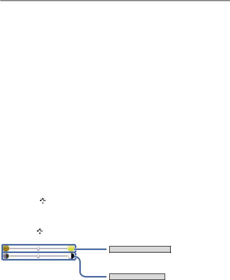
3.4 Backlight and Contrast Adjustment
Press and hold  > 2 seconds to enter the backlight brightness and display contrast adjustment mode. Press
  and
and  to select brightness or contrast adjustment. Press
  and
and  to adjust the levels of brightness/contrast. Press the
  to save the setting and exit the adjustment mode.
Press  or
or  Key again to cancel the adjustment and exit the adjustment mode.
Brightness adjustment
Backlight brightness can be changed by 11 levels.
Contrast adjustment
Contrast can be changed by 11 levels.
22

3. Basic operations
3.5 Screens
Inst/ Integration/ Demand values 
Press the  button to toggle the screens.
|
W (Inst value) |
|
Wh (Integration value) |
|
|
Demand |
|
|
|
|
|
|
|
|
|
|
|
|
|
|
|
|
|
|
|
|
|
|
|
|
|
|
|
|
|
 Customize
Select and change the items to be displayed.
Zoom
Zoom and display the selected items.
4-split |
|
8-split |
|
|
|
Trend
Changes to the measured values are displayed on a graph to track trends.
Zoom |
Zoom out |
23
3. Basic operations
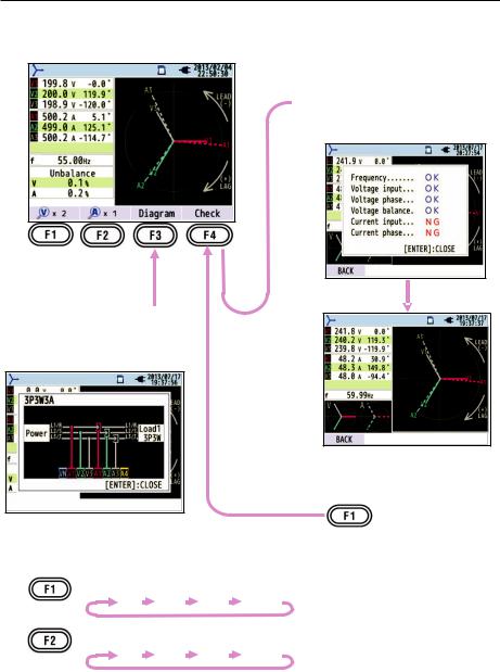
Vector 
 Wiring check
Checked results will be displayed.
Wiring diagram 
Diagram of the selected wiring is displayed.
: toggle the line lengths of voltage vector.
1 |
2 |
5 |
10 |
|
* time(s) |
|
|||||
: toggle the line lengths of current vector. |
|||||
1 |
2 |
5 |
10 |
|
* time(s) |
|
|||||
24

3. Basic operations
Waveform 
Select the items with up and down  keys and check for the waveforms.
Measured values per CH
: toggle the magnifications of voltage waveform (vertical). 0.1  0.5
0.5  1
1  2
2  5
5  10
10  * time(s)
: toggle the magnifications of current waveform (vertical). 0.1  0.5
0.5  1
1  2
2  5
5  10
10 
: toggle the magnifications of time axis (horizontal). 1  2
2  5
5  10
10  * time(s)
Restore all the changed magnification settings and automatically select the appropriate magnification.
25
3. Basic operations
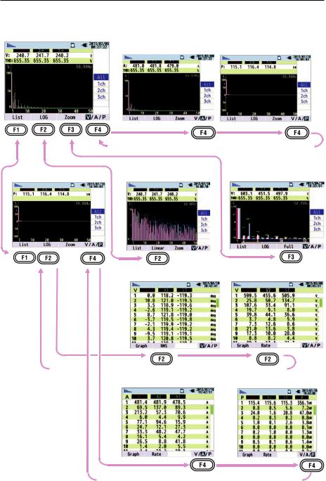
Harmonics 
Voltage, Linear, Overall display
|
|
|
Current |
|
Power |
|
|
|
|
|
|
|
|
|
|
|
|
|
|
|
List, Rate of content |
Logarithm |
Zoom |
||
|
|
|
|
|
|
|
|
|
|
|
|
|
|
|
|
Phase angle |
RMS value |
||
|
|
|
|
|
|
|
|
|
|
|
Current |
|
Power |
|
|
|
|
|
|
|
|
|
|
|
26
 Loading...