

AT-6010 Advanced Wire Tracer Kit
Wire tracing made simple
With the AT-6010 Advanced Wire Tracer, it’s never been easier and safer to locate Energized and
De-energized wires, breakers and fuses. When the Transmitter is connected to the circuit, the Receiver easily
detects the signal in the wires or cables behind walls, ceilings and oors. The Transmitter works on Energized and
De-energized circuits up to 600 V AC/DC in Category I through Category III electrical environments, allowing for
work directly on an energized circuit without the need to take equipment ofine. The Transmitter also features high
signal mode for general tracing and a loop mode designed specically for locating shorts, as well as two optimal
tracing frequencies that are automatically activated based on the detected voltage. The complete AT-6010 kit
features test leads and accessories International accessory kit for use outside North America.
Features
• Large LCD Receiver screen
with two digit readout, bar
graph and sound to easily
determine wire location
• Simple one button
Transmitter operation
• Compatible with the CT-400
Signal Clamp accessory for
inducing a tracing signal on
the cable when there is no
access to bare conductors
Main Applications
• Trace energized
and de-energized wires
• Identify breakers and fuses
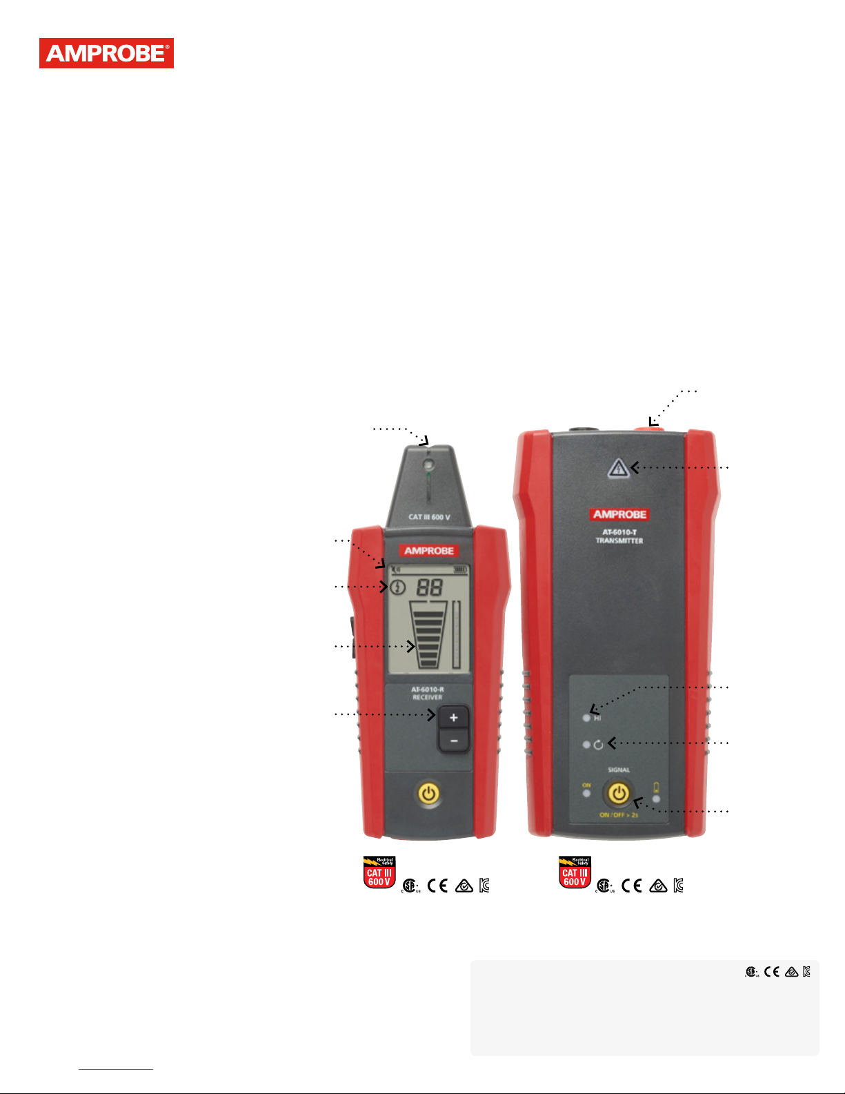
Large black &
white LCD screen
De-energized
Signal strength
Tip Sensor
to trace wires in
tight spaces
Energized/
indicator
bar graph
amprobe.com
Compatible with
standard test leads
Voltage
warning
indicator
Special Applications
• Connect to GFCI protected
circuits
• Find breaks and opens
• Find shorts
• Trace wires in metal conduit
• Trace non-metallic pipes and
conduit
• Trace shielded wires
• Trace underground wires
• Trace low voltage wires and
data cables
• Sort bundled wires
• Map a circuit with test leads
• Trace breakers on system with
light dimmers
• Signal clamp- closed loop
circuits
• Signal clamp- mapping circuits
Sensitivity
adjustment
AT-6010-R
Receiver
HI mode for
general wire
tracing
Loop mode for
nding shorts
Simple
one button
operation
AT-6010-T
Transmitter
Safety Certication
All Amprobe tools, including the Amprobe AT-6010, are rigorously tested
for safety, accuracy, reliability, and ruggedness in our state-of-the-art
test lab. In addition, Amprobe products that measure electricity are listed by a
3rd party safety lab, either UL or CSA. This system assures that Amprobe products
meet or exceed safety regulations and will perform in a tough, professional
environment for many years to come.
©2019 Amprobe® For detailed specications and ordering go to amprobe.com 6012031-AAmprobe® | info@amprobe.com | Fluke Corporation, Everett, WA 98203 | Tel: 877-AMPROBE (267-7623)

amprobe.com
The CT-400 Signal
Clamp is an
optional accessory,
Features and
specications
Features
Measurement category CAT III 600 V CAT III 600 V CAT IV 600 V, CAT III 1000 V
Operating voltage 0 to 600 V AC/DC 0 to 600 V AC/DC 0 to 1000 V AC
Operating frequency Energized: 6.25 kHz, De-Energized: 32.768 kHz Energized: 6.25 kHz, De-Energized: 32.768 kHz
Hazardous voltage detection – > 30 V AC/DC –
Signal indications Numeric, bar graph display and audible beep LEDs –
Response time
Current output of signal
(typical)
Signal voltage output
(nominal)
Range detection (open air)
Specications
Display size LCD 2.5 in (6.35 cm) – –
Display dimensions (W x H) 1.45 x 1.93 in (36.72 x 48.96 mm) – –
Display type Segment LCD LEDs –
Display color Black and white Operating mode LEDs: red, Battery status LEDs: red –
Booting time < 3 sec < 2 sec –
Backlight • – –
Operating temperature -4 °F to 122 °F (-20 °C to 50 °C) 32 °F to 122 °F (0 °C to 50 °C)
Operating humidity
Storage temperature and
humidity
Operating altitude 0 to 6561 ft (2000 m) 0 to 6561 ft (2000 m)
Transient protection – 6.00 kV (1.2/50μS surge) –
Pollution degree 2 2 2
IP rating IP 52 IP 40 IP 40
Drop test 3.28 ft (1 m) 3.28 ft (1 m) 3.28 ft (1 m)
Power supply 4 x AA (alkaline) 8 x AA (alkaline) –
Power consumption (typical) 70 mA
Battery life Approx. 25 h
Low battery indication • • –
Fuse – 1.6 A, 700 V, fast-acting, Ø 6x32mm –
Maximum conductor Size – – 1.26 in (32 mm)
Dimensions (L x W x H) Approx. 7.2 x 2.95 x 1.69 in (183 x 75 x 43 mm) Approx. 7.2 x 3.66 x 1.97 in (183 x 93 x 50 mm)
Weight Approx. 0.6 lb (0.27 kg) Approx. 1.25 lb (0.57 kg) Approx. 0.25 lb (0.114 kg)
Certications
NOTE: Refer to user manual for accessory specications
AT-6010-R Receiver AT-6010-T Transmitter
Tip Sensor (Energized/De-energized): 500 ms
Battery voltage monitoring: 5 sec
–
–
Tip sensor (Energized):
Max distance via air: up to 20 ft (6.1 m)
Pinpointing: approx. 1.97 in (5 cm)
Tip sensor (De-energized):
Max distance via air: up to 14.7 ft (4.5 m)
Pinpointing: approx. 1.97 in (5 cm)
45%: -4 °F to <50 °F (-20 °C to <10 °C), 95%: 50 °F to <86 °F (10 °C to <30 °C)
75%: 86 °F to <104 °F (30 °C to <40 °C), 45%: 104 °F to 122 °F (40 °C to 50 °C)
-4 °F to 158 °F (-20 °C to 70 °C), <95% RH -4 °F to 158 °F (-20 °C to 70 °C), <95% RH
Line voltage monitoring: 1 sec
Battery voltage monitoring: 5 sec
Energized circuit: HI mode: 60 mA RMS
De-energized circuit: HI mode: 130 mA RMS
Loop mode: 160 mA RMS
De-energized circuit: HIGH: 33V RMS, 140 Vp-p
With CT-400: loop mode: 31 V RMS, 120 Vp-p
– –
Hi mode: 70 mA
Loop mode with Clamp: 90 mA
Consumption without signal transmission: 10 mA
Hi mode: approx. 25 h
Loop mode: approx. 18 h
CT-400 Signal Clamp
Wire tracing: 32.768 kHz
AC current measurement: 45 Hz to 400 Hz
1 mA/A for AC current measurement
with multimeter
De-energized circuit:
2.4 V RMS, 24 Vp-p
95%: 50 °F to <86 °F (10 °C to <30 °C)
75%: 86 °F to <104 °F (30 °C to <40 °C)
45%: 104 °F to <122 °F (40 °C to <50 °C)
Approx. 5.9 x 2.75 x 1.18 in
(150 x 70 x 30 mm)
not included in the
AT-6010 Kit.
Instantaneous
–
–
Trace energized and de-energized wires Identify the single correct breaker Locate a specic wire
©2019 Amprobe® For detailed specications and ordering go to amprobe.com 6012031-AAmprobe® | info@amprobe.com | Fluke Corporation, Everett, WA 98203 | Tel: 877-AMPROBE (267-7623)
 Loading...