

Page 1

AM-510
Commercial /
Residential
Multimeter
User Manual
ENG FRE
SPA
Page 2

Page 3

AM-510
Commercial / Residential
Multimeter
User Manual
1/2018, Rev.2
©2018 Amprobe Test Tools.
All rights reserved. Printed in China
English
Page 4

Limited Warranty and Limitation of Liability
Your Amprobe product will be free from defects in material and workmanship for one year from
the date of purchase unless local laws require otherwise. This warranty does not cover fuses,
disposable batteries or damage from accident, neglect, misuse, alteration, contamination, or
abnormal conditions of operation or handling. Resellers are not authorized to extend any other
warranty on the behalf of Amprobe. To obtain service during the warranty period, return the
product with proof of purchase to an authorized Amprobe Service Center or to an Amprobe
dealer or distributor. See Repair Section for details. THIS WARRANTY IS YOUR ONLY REMEDY.
ALL OTHER WARRANTIES - WHETHER EXPRESS, IMPLIED OR STATUTORY - INCLUDING IMPLIED
WARRANTIES OF FITNESS FOR A PARTICULAR PURPOSE OR MERCHANTABILITY, ARE HEREBY
DISCLAIMED. MANUFACTURER SHALL NOT BE LIABLE FOR ANY SPECIAL, INDIRECT, INCIDENTAL
OR CONSEQUENTIAL DAMAGES OR LOSSES, ARISING FROM ANY CAUSE OR THEORY. Since
some states or countries do not allow the exclusion or limitation of an implied warranty or of
incidental or consequential damages, this limitation of liability may not apply to you.
Repair
All Amprobe returned for warranty or non-warranty repair or for calibration should be
accompanied by the following: your name, company’s name, address, telephone number, and
proof of purchase. Additionally, please include a brief description of the problem or the service
requested and include the test leads with the meter. Non-warranty repair or replacement charges
should be remitted in the form of a check, a money order, credit card with expiration date, or a
purchase order made payable to Amprobe.
In-warranty Repairs and Replacement – All Countries
Please read the warranty statement and check your battery before requesting repair. During the
warranty period, any defective test tool can be returned to your Amprobe distributor for an exchange
for the same or like product. Please check the “Where to Buy” section on amprobe.com for a list
of distributors near you. Additionally, in the United States and Canada, in-warranty repair and
replacement units can also be sent to an Amprobe Service Center (see address below).
Non-warranty Repairs and Replacement – United States and Canada
Non-warranty repairs in the United States and Canada should be sent to an Amprobe Service
Center. Call Amprobe or inquire at your point of purchase for current repair and replacement rates.
USA Canada
Amprobe Amprobe
Everett, WA 98203 Mississauga, ON L4Z 1X9
Tel: 877-AMPROBE (267-7623) Tel: 905-890-7600
Non-Warranty Repairs and Replacement – Europe
European non-warranty units can be replaced by your Beha-Amprobe distributor for a nominal charge.
Please check the “Where to Buy” section on beha-amprobe.com for a list of distributors near you.
Beha-Amprobe
Division and reg. trademark of Fluke Corp. (USA)
Germany* United Kingdom The Netherlands - Headquarters**
In den Engematten 14 52 Hurricane Way Science Park Eindhoven 5110
79286 Glottertal Norwich, Norfolk 5692 EC Son
Germany NR6 6JB United Kingdom The Netherlands
Phone: +49 (0) 7684 8009 - 0 Phone: +44 (0) 1603 25 6662 Phone: +31 (0) 40 267 51 00
beha-amprobe.de beha-amprobe.com beha-amprobe.com
*(Correspondence only – no repair or replacement available from this address. European customers please
contact your distributor.)
**single contact address in EEA Fluke Europe BV
Page 5

AM-510 Commercial / Residential Multimeter
6
1
2
3
4
5
10
9
Flash light
1
LCD Display
2
Function Buttons
3
Input Terminal for voltage, frequency, diode,
7
capacitance, resistance and continuity measurement
COM (return) terminal for all measurements
8
Input Terminal for battery test and AC/DC mA or μA
9
measurement
10
Input Terminal for AC/DC A measurement to10A
Flash light Button
4
Rotary Switch
5
SELECT Button
6
7
8
Page 6
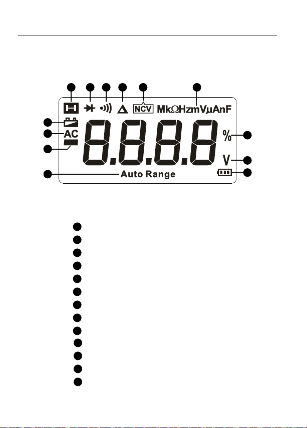
Screen Display
5
4
3
2
1
10
11
12
13
76 8 9
The Meter selects the range with best resolution
1
Negative reading
2
Alternate Current
3
Low battery indicator
4
Data hold
5
Diode test
6
Continuity test
7
Relative zero mode
8
Non-Contact Voltage
9
Measurement units
Duty Cycle
Measurement unit for voltage
Battery Test
10
11
12
13
Page 7

AM-510 Commercial / Residential Multimeter
CONTENTS
SYMBOLS ...............................................................................................................2
SAFETY INFORMATION .........................................................................................2
UNPACKING AND INSPECTION .............................................................................3
FEATURES ...............................................................................................................4
MAKING MEASUREMENT .....................................................................................5
Measuring AC and DC Voltage .........................................................................6
Measuring AC and DC Current .........................................................................7
Measuring Resistance .......................................................................................8
Measuring Continuity .......................................................................................9
Measuring Diode ...............................................................................................9
Measuring Capacitance ....................................................................................10
Measuring Frequency .......................................................................................10
Non-Contact Voltage Sensing ..........................................................................11
Battery Test ........................................................................................................12
SPECIFICATION .......................................................................................................12
MAINTENANCE AND REPAIR ................................................................................17
BATTERY AND FUSE REPLACEMENT .....................................................................18
1
Page 8

SYMBOLS
Caution! Risk of electric shock.
Caution! Refer to the explanation in this Manual
Alternating Current (AC)
Direct Current (DC)
The equipment is protected by double insulation or reinforced
insulation
Earth (Ground)
Audible tone
Battery
Complies with European Directives
Conforms to relevant Australian standards
Canadian Standards Association (NRTL/C)
Do not dispose of this product as unsorted municipal waste. Contact
a qualified recycler.
SAFETY INFORMATION
The Meter complies with:
IEC/EN 61010-1 3rd Edition, UL61010-1 2nd Ed. and CAN/CSA C22.2 No.
61010.1-0.92 to Category III 600 Volts, Pollution degree 2
IEC/EN 61010-2-030
IEC/EN 61010-2-31 for test leads
EMC IEC/EN 61326-1
Measurement Category III (CAT III) is for measurements performed in the
building installation. Examples are measurements on distribution boards,
circuit- breakers, wiring, including cables, bus-bars, junction boxes, switches,
socket-outlets in the fixed installation, and equipment for industrial use
and some other equipment, for example, stationary motors with permanent
connection to the fixed installation.
2
Page 9

CENELEC Directives
The instruments conform to CENELEC Low-voltage directive 2014/35/EC and
Electromagnetic compatibility directive 2014/30/EC
Warning: Read Before Using
• To avoid possible electrical shock or personal injury, follow these
instructions and use the Meter only as specified in this manual.
• Do not use the Meter or test leads if they appear damaged, or if the
Meter is not operating properly. If in doubt, have the Meter serviced.
• Always use the proper function and range for measurements.
• Before rotating the function range selection switch, disconnect test
probe from circuit under test.
• Verify the Meter’s operation by measuring on a known voltage source.
• Do not apply more than the rated voltage, as marked on the Meter,
between the test probe or between any test probe and earth ground.
• Use the Meter with caution for voltages above 30 Vac rms, 42 Vac peak,
or 60 Vdc. These voltages pose electrical shock hazards.
• Disconnect circuit power and discharge all high-voltage capacitors before
testing resistance.
• Do not use the Meter around explosive gas or vapor.
• When using the test leads, keep your fingers behind the finger guards.
• Remove test leads from the Meter before opening the Meter case or
battery door.
UNPACKING AND INSPECTION
Your shipping carton should include:
1 AM-510 Multimeter
1 Pair of test leads
1 9V (6F22) battery (installed)
1 Users manual
If any of the items are damaged or missing, return the complete package to
the place of purchase for an exchange.
3
Page 10

FEATURES
The digital multimeter designed for advanced residential applications. Rewire
an electrical panel, install heated floors or new light fixtures, troubleshoot and
repair home appliances, electrical sockets and automotive electrical problems
with this easy-to-use multimeter. The AM-510 features a built-in flashlight
to see wires in the dark, a kick stand, and probe holder to give you the
“third-hand” you need while taking measurements and non-contact voltage
detection for quick go-no-go checks without the need for an additional tool.
Compact yet tough, this multimeter is built to last through all your electrical
projects.
• Measurements: Voltage up to 600V AC/DC, AC/DC Current and Resistance
• Frequency, Capacitance, Duty Cycle for troubleshooting applications
• Special Functions:
- Non-contact Voltage Detection
- Audible continuity
- Diode Test
• Backlit LCD display
• Events:
- Data hold
- Relative zero mode
• Built in work light (flashlight)
• Built in test leads storage and “third hand” probe holder
• Auto and Manual ranging
• Auto power off
• Low battery warning
• Safety: CAT III 600V
4
Page 11

MAKING MEASUREMENT
1. Use the proper function and range for measurements.
2. To avoid possible electrical shock, personal injury or damages to the
Meter, disconnect circuit power and discharge all high-voltage capacitors
before testing resistance and diode.
3. Connecting test leads:
• Connect the common (COM) test lead to the circuit before connecting
the live lead;
• After measurement, remove live lead before removing the common
(COM) test lead from the circuit
4. Symbol “OL” is displayed on LCD when the measurement is out of range.
Rotary Switch Positions
Switch Position Measurement Function
V
Hz Frequency measurement
% Duty cycle
NCV Non-contact voltage
mA A
μA
AC or DC voltage measurement (use SELECT button for
switching to AC or DC).
Resistance measurement
Voltage measurement of diode PN junction
Continuity measurement
Capacitance measurement
9V For measurement of dry batteries of not exceeding 15Vdc
1.5V For measurement of dry batteries of not exceeding 2Vdc
AC or DC current measurement (use SELECT button for
switching to AC or DC).
Rotary Switch Positions
Button Measurement Function
SELECT
Press the yellow SELECT button to select alternate
measurement functions on the rotary switch.
5
Page 12

HOLD /
Press
REL
RANGE
Hz / %
to enable the function when at relevant rotary switch function.
Display freezes present reading / press 2 sec to turn on
LCD backlight.
Relative zero mode
Manual or Auto range switching. The default setting
is Auto ranging, press to switch to manual ranging
(selectable resolutions). Press for 2 sec to return to auto
ranging.
Frequency / Duty Cycle. Press to turn on Frequency
measurement mode; press again for duty cycle
measurement.
Flash light
Auto Power OFF
Auto power off: approx. 30 minutes.
When the Meter is in auto power off mode, press any button to resume
normal operation.
Measuring AC and DC Voltage
To avoid personal injury or damage to the Meter, do not apply voltage
higher than 600V.
Auto Range
/Manual Range
6
Page 13

Measuring AC and DC Current
Press SELECT button to select AC or DC current measurement function.
To avoid personal injury or damage to the Meter:
1. Do not attempt to make an in-circuit current measurement when the
open-circuit potential to earth ground exceeding 600V.
2. Switch to proper function and range for your measurement.
3. Do not place the test probe in parallel with a circuit when the test leads
are connected to the current terminals.
4. Connect the test leads to the correct input A/mA μA current terminal and
to the circuit before powering the circuit under test.
5. For current range from 8-10A, do not measure current for more than 20
minutes. Wait for 10 minutes before taking another measurement
6. After measurement, switching OFF the circuit’s power before removing
test leads from the circuit.
AC/DC
RL
Auto Range
/Manual Range
RL
7
Page 14

AC/DC
RL
Auto Range
/Manual Range
RL
Measuring Resistance
Disconnect circuit power and discharge all high-voltage capacitors
before testing resistance.
R
Note:
On a higher resistance measurement (>1M), the measurement may take a
few seconds to get stable reading.
Over range or open circuit indication: OL
8
Page 15

Measuring Continuity
Disconnect circuit power and discharge all high-voltage capacitors
before testing continuity.
R 1 0
R 150
Measuring Diode
Disconnect circuit power and discharge all high-voltage capacitors
before testing diode.
D
9
Page 16
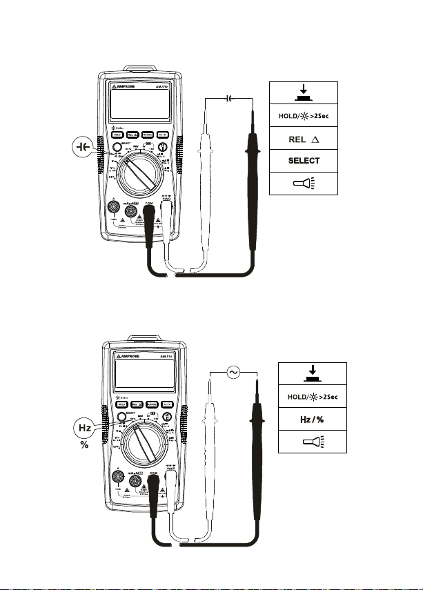
Measuring Capacitance
Disconnect circuit power and discharge all high-voltage capacitors
before testing capacitance.
Auto Range
C
Measuring Frequency
Press Hz/% button to select Frequency / Duty Cycle measurement function.
To avoid personal injury or damage to the Meter, do not apply voltage
higher than 600V.
Auto Range
10
Page 17
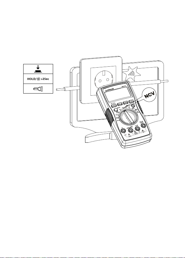
Non-Contact Voltage Sensing
1. To avoid personal injury or damage to the Meter, do not test on
un-insulated high voltage wires.
2. Buzzer will sound when detecting voltage higher than AC 90V. Screen
displays“OL”.
3. Do not test on hazardous live wires higher than AC 600V.
11
Page 18
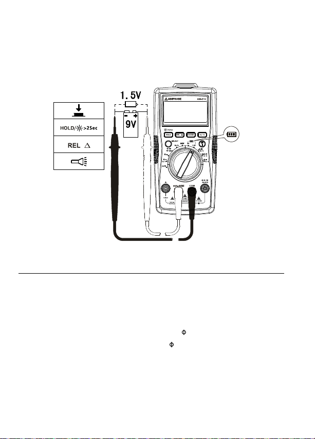
Battery Test
Applying a voltage source or incorrect battery type under battery test
may cause personal injury or damage to the Meter.
Battery 1.5V range is for dry battery not exceeding 2Vdc. The resistance load
is around 30Ω.
Battery 9V range is for dry battery not exceeding 15Vdc. The resistance load
is around 1KΩ.
SPECIFICATION
Ambient temperature: 23°C ±5°C (73.4°F ±9°F)
Relative temperature: ≤75%
Accuracy: ±(% of reading + digits)
Maximum voltage between input terminal and earth ground: AC 600Vrms or
DC 600V
Fuse for mA μA input: 0.5A H 660V fast-fuse, 6.3×32mm.
Fuse for 10A input: 10A H 660V fast-fuse, 6.3×32mm.
Maximum display: Digital 3999 counts, updates 3/sec. Frequency: 4999 counts.
Over-range indication: OL
Range: Automatic
Altitude: Operating ≤ 2000m
Operating temperature: 0°C ~ +40°C (32°F ~ 104°F)
12
Page 19
Relative humidity: 0°C ~ +30°C (32°F ~ 86°F) ≤75%; +30°C ~ +40°C (86°F ~
104°F) ≤50%
Storage temperature: -10°C ~ +50°C (14°F ~ 122°F)
Electromagnetic compatibility: In an RF filed of 1V/m = Specified accuracy ±5%
Battery: 9V, 6F22, NEDA1604 or equivalent
Low battery indication:
Dimensions (L x W x H): 182 mm x 90 mm x 45 mm (7.2 in x 3.5 in x 1.8 in)
Weight: Approx. 354g (0.78lb) with batteries installed
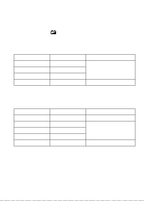
1. DC Voltage Measurement
Range Resolution Accuracy
4.000V 1mV
±(0.8%+1dgt)40.00V 10mV
400.0V 100mV
600V 1V ±(1.0%+3dgt)
Input impedance: around 10MΩ; (Input impedance > 3GΩ for DC 400mV
range)
Overload protection: ±600V
2. AC Voltage Measurement
Range Resolution Accuracy
400.0mV 0.1mV ±(1.2%+3dgt)
4.000V 1mV
±(1.0%+3dgt)40.00V 10mV
400.0V 100mV
600V 1V ±(1.2%+3dgt)
Note: 400.0mV range is available for manual range only.
Input impedance: around 10MΩ
Frequency response: 45Hz ~ 400Hz
Average sensing, rms indication.
Overload protection: 600Vrms
13
Page 20
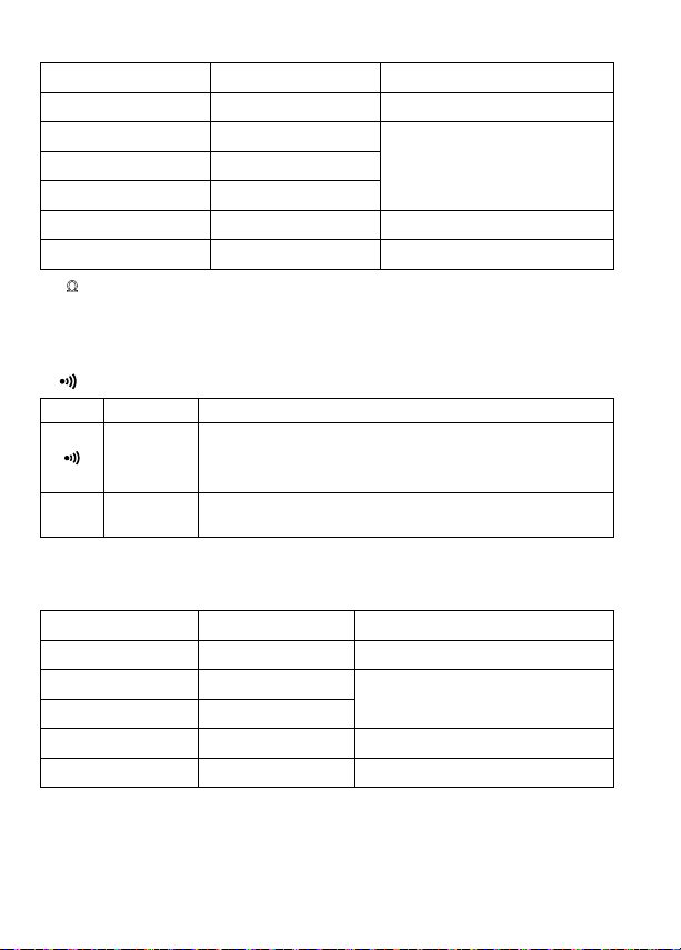
3. Resistance Measurement
Range Resolution Accuracy
400.0Ω 0.1Ω ±(1.2%+2dgt)
4.000kΩ 1Ω
±(1.0%+2dgt)40.00kΩ 10Ω
400.0kΩ 100Ω
4.000MΩ 1kΩ ±(1.2%+2dgt)
40.00MΩ 10kΩ ±(1.5%+5dgt)
Ω range: Measured value = (Measured display value) – (Short-circuiting
400
value of probe)
Open circuit voltage: around 0.5V
Overload protection: 600Vrms
4. : Continuity : Diode measurement
Range Resolution Accuracy
Open circuit voltage is around 0.5V.
0.1Ω
Overload protection: 600Vrms
1mV
Resistance >150Ω, buzzer will not sound.
Resistance ≤10Ω, buzzer will sound.
Open-circuit voltage is around 1.5V. Normal voltage is
around 0.5V to 0.8V for silicon PN junction.
5. Capacitance Measurement
Range Resolution Accuracy
40.00nF 10pF ±(3%+10dgt) under REL status
400.0nF 100pF
4.000uF 1nF
40.00uF 10nF ±(3%+5dgt)
100.0uF 100nF ±(4%+5dgt)
Overload protection: 600Vrms
±(3%+5dgt) under REL status
14
Page 21
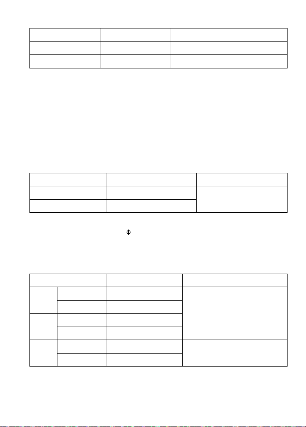
6. Measurement of frequency/duty cycle
Range Resolution Accuracy
10Hz~10MHz 0.01Hz~0. 01MHz ±(0.1%+4dgt)
0.1%~99.9% 0.1% --
Overload protection: 600Vrm
Input amplitude: (DC level is 0.)
10Hz~1MHz: 300mV ≤ a ≤30Vrms
>1MHz~10MHz: 600mV ≤ a ≤30Vrms
Input amplitude and frequency response must meet following conditions when
reading frequency or duty cycle during AC voltage or current measurement
• Input amplitude ≥ Range × 30%
• Frequency response: ≤400Hz
7. Battery Test
Range Internal load resistance Accuracy
1.5V About 30Ω
9V About 1kΩ
Overload protection:
±(1.0%+3dgt)
F1 0.5A H 660V fast-fuse, 6.3×32mm
For 1.5V range: Load resistance is around 30Ω.
For 9V range: Load resistance is around 1kΩ
8. DC Current Measurement
Range Resolution Accuracy
400.0μA 0.1μA
μA
mA
4000μA 1μA
40.00mA 10μA
400.0mA 0.1mA
4.000A 1mA
A
10.00A 10mA
±(1.0%+2dgt)
±(1.2%+3dgt)
15
Page 22
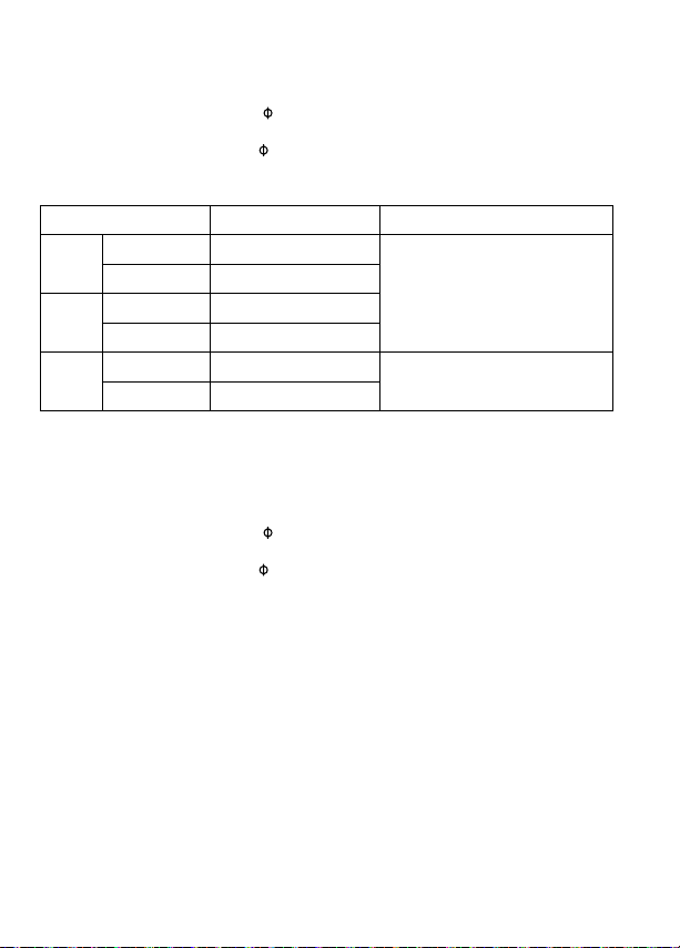
Overload protection:
mA /μA input:
F1 fuse, 0.5A H 660V fast-fuse,
10 A input:
F2 fuse, 10A H 660V fast-fuse, 6.3×32mm
6.3×32mm
9. AC Current Measurement
Range Resolution Accuracy
400.0μA 0.1μA
μA
mA
Frequency response: 45Hz ~ 400Hz
Average sensing, rms indication
Overload protection:
4000μA 1μA
40.00mA 10μA
400.0mA 0.1mA
A
4.000A 1mA
10.00A 10mA
mA /μA input:
F1 fuse, 0.5A H 660V fast-fuse,
10 A input:
F2 fuse, 10A H 660V fast-fuse, 6.3×32mm
6.3×32mm
±(1.2%+2dgt)
±(1.5%+3dgt)
16
Page 23

MAINTENANCE AND REPAIR
If the Meter fails to operate, check battery, test leads, etc., and replace as
necessary.
Double check the followings:
1. Replace the fuse or battery if the meter does not work.
2. Review the operating instructions for possible mitestledningers in
operating procedure.
Quick check on 0.5A FUSE:
Step 1: Turn the rotary switch to Ω function.
Step 2: Connect test lead to /V/Ω/Hz terminal and mA/μA terminal.
Resistance reading ≤ 10MΩ: the fuse is OK
Resistance reading “OL”: the fuse is open. Replace the fuse as specified.
Quick check on 10A FUSE:
Step 1: Turn the rotary switch to Ω function.
Step 2: Connect test lead to /V/Ω/Hz terminal and mA/μA terminal.
Resistance reading ≤ 0.5Ω: the fuse is OK.
Resistance reading “OL”: the fuse is open. Replace the fuse as specified.
Auto Range
/Manual Range
17
Page 24

Except for the replacement of the battery, repair of the meter should be
performed only by a Factory Authorized Service Center or by other qualified
instrument service personnel.
The front panel and case can be cleaned with a mild solution of detergent and
water. Apply sparingly with a soft cloth and allow to dry completely before
using. Do not use aromatic hydrocarbons, Gasoline or chlorinated solvents for
cleaning.
BATTERY AND FUSE REPLACEMENT
WARNING
To avoid shock, injury, or damage to the Meter:
Disconnect test leads before opening case.
Use ONLY fuses with the amperage, interrupt, voltage, and speed ratings
specified.
Replacing BATTERY follow below steps:
1. Disconnect the test lead probe from measuring circuit.
2. Turn the Meter to OFF position.
3. Remove the screws from the battery cover and open the battery cover
4. Remove the batteries and replace with one 9V (6F22) or equivalent. The
battery cover provides the correct polarity fitting construction design.
Install the battery in the battery cover.
5. Put the battery cover back and re-fasten the screw.
Battery: 9V (6F22) Battery or equivalent
Replacing FUSE follow below steps:
1. Disconnect the test lead probe from measuring circuit.
2. Turn the Meter to OFF position.
3. Remove the screws from the enclosure and open the enclosure.
4. Remove the broken fuse and replace with new specified fuse.
5. Put the enclosure back and re-fasten the screw.
18
Page 25

Fuse ratings:
mA /μA input terminal:
F1 fuse, 0.5A H 660V fast-fuse,
6.3×32mm
10 A input terminal:
F2 fuse, 10A H 660V fast-fuse, 6.3×32mm
9V Battery
19
Page 26

Page 27

AM-510
Multimètre numérique
commercial / résidentiel
Mode d’emploi
1/2018, Rév.2
©2018 Amprobe Test Tools.
Tous droits réservés. Imprimé en Chine.
Français
Page 28

Limites de garantie et de responsabilité
Amprobe garantit l’absence de vices de matériaux et de fabrication de ce produit pendant
une période d’un an prenant effet à la date d’achat, sauf disposition contraire prévue par
la loi. Cette garantie ne s’applique pas aux fusibles, aux piles jetables ni à tout produit mal
utilisé, modifié, contaminé, négligé ou endommagé par accident ou soumis à des conditions
anormales d’utilisation et de manipulation. Les revendeurs n’ont pas l’autorisation de
prolonger toute autre garantie au nom d’Amprobe. Pour bénéficier de la garantie, renvoyez
le produit accompagné d’un justificatif d’achat auprès d’un centre de services agréé par
Amprobe ou d’un distributeur ou d’un revendeur Amprobe. Voir la section Réparation pour
tous les détails. LA PRÉSENTE GARANTIE EST LE SEUL ET EXCLUSIF RECOURS DE L’UTILISATEUR
TOUTES AUTRES GARANTIES, EXPLICITES, IMPLICITES OU STATUTAIRES, NOTAMMENT
LE CAS ÉCHÉANT LES GARANTIES DE QUALITÉ MARCHANDE OU D’ADAPTATION À UN
OBJECTIF PARTICULIER SONT EXCLUES PAR LES PRÉSENTES. LE FABRICANT NE SERA EN
AUCUN CAS TENU RESPONSABLE DE DOMMAGES PARTICULIERS, INDIRECTS, ACCIDENTELS
OU CONSÉCUTIFS, NI D’AUCUNS DÉGATS OU PERTES DE DONNÉES, SUR UNE BASE
CONTRACTUELLE, EXTRA-CONTRACTUELLE OU AUTRE. Étant donné que certaines juridictions
n’admettent pas les limitations d’une condition de garantie implicite ou l’exclusion ou la
limitation de dégâts accidentels ou consécutifs, il se peut que les limitations et les exclusions
de cette garantie ne s’appliquent pas à votre cas.
Réparation
Tous les outils de test renvoyés pour être réparés au titre de la garantie ou pour étalonnage
doivent être accompagnés des éléments suivants : nom, raison sociale, adresse, numéro de
téléphone et justificatif d’achat. Ajoutez également une brève description du problème ou du
service demandé et incluez les cordons de test avec l’appareil. Les frais de remplacement ou
de réparation hors garantie doivent être acquittés par chèque, mandat, carte de crédit avec
date d’expiration, ou par bon de commande payable à l’ordre de Amprobe®.
Remplacements et réparations sous garantie – Tous pays
Veuillez lire la déclaration de garantie et vérifiez la pile avant de demander une réparation.
Pendant la période de garantie, tout outil de test défectueux peut être renvoyé auprès de
votre distributeur Amprobe® pour être échangé contre un produit identique ou similaire.
Consultez la section « Where to Buy » sur le site www.amprobe.com pour obtenir la liste des
distributeurs dans votre région. Les appareils sous garantie devant être remplacés ou réparés
au Canada et aux États-Unis peuvent également être envoyés dans un centre de services
Amprobe® (voir les adresses ci-dessous).
Remplacements et réparations hors garantie – Canada et États-Unis
Les appareils à réparer hors garantie au Canada et aux États-Unis doivent être envoyés dans
un centre de services Amprobe®. Appelez Amprobe® ou renseignez-vous auprès de votre lieu
d’achat pour connaître les tarifs en vigueur de remplacement ou de réparation.
Aux États-Unis et au Canada
Amprobe Amprobe
Everett, WA 98203 Mississauga, ON L4Z 1X9Canada
Tél. : 877-AMPROBE (267-7623) Tél. : 905-890-7600
Remplacements et réparations hors garantie – Europe
Les appareils européens non couverts par la garantie peuvent être remplacés par votre
distributeur Amprobe® pour une somme nominale. Consultez la section « Where to Buy » sur
le site www.metermantesttools.com pour obtenir la liste des distributeurs dans votre région.
Adresse postale européenne*
Amprobe® Europe
Beha-Amprobe GmbH
In den Engematten 14
79286 Glottertal, Allemagne
Tél. : +49 (0) 7684 8009 - 0
www.amprobe.eu
*(Réservée à la correspondance – Aucun remplacement ou réparation n’est possible à cette
adresse. Nos clients européens doivent contacter leur distributeur.)
Page 29

AM-510 Multimètre numérique commercial/résidentiel
1
2
3
6
4
5
10
9
Lampe-torche
1
Afficheur LCD
2
Boutons de fonction
3
Borne d’entrée pour les mesures de tension, de fréquence, de
7
résistance, de capacité, le contrôle de diode et de continuité
Borne de retour COM pour toutes les mesures
8
Borne d’entrée pour le test de piles et les mesures mA ou μA
9
ac/dc
10
Borne d'entrée pour les mesures A ac/dc jusqu'à 10 A
Bouton de lampe-torche
4
Sélecteur rotatif
5
Bouton de sélection
6
7
8
Page 30

Affichage
5
4
3
2
1
Le multimètre numérique sélectionne la gamme avec
1
la meilleure résolution
Lecture négative
2
Mesure alternative
3
Témoin de pile faible
4
Maintien des données affichées
5
Contrôle de diode
6
Contrôle de continuité
7
Mode du zéro relatif
8
Tension sans contact
9
10
Unités de mesure
11
Rapport cyclique
12
Unités de mesure de la tension
13
Test de piles
76 8 9
10
11
12
13
Page 31

AM-510 Multimètre numérique commercial/résidentiel
TABLE DES MATIÈRES
SYMBOLES .............................................................................................................2
CONSIGNES DE SÉCURITÉ .....................................................................................2
DÉBALLAGE ET INSPECTION .................................................................................3
FONCTIONNALITÉS ................................................................................................4
OPÉRATIONS DE MESURE .....................................................................................5
Mesures de tension alternative et continue ....................................................6
Mesures de courant alternatif et continu .......................................................7
Mesures de résistance .......................................................................................8
Mesures de continuité ......................................................................................9
Contrôle de diode .............................................................................................9
Mesure de capacité ...........................................................................................10
Mesure de fréquence ........................................................................................10
Détection de tension sans contact ...................................................................11
Test de piles .......................................................................................................12
CARACTÉRISTIQUES ..............................................................................................12
ENTRETIEN .............................................................................................................17
REMPLACEMENT DES FUSIBLES ET DES PILES .....................................................18
1
Page 32

SYMBOLES
Attention ! Risque de décharge électrique
Attention ! Se reporter aux explications de ce manuel
Courant alternatif (ac)
Courant continu (dc)
L’équipement est protégé par une double isolation ou une isolation
renforcée
Prise de terre
Signal sonore
Batterie
Conforme aux directives européennes
Conforme aux directives de l'association australienne de
normalisation
Association canadienne de normalisation (CSA)
Ne pas mettre ce produit au rebut parmi les déchets ménagers.
Consulter un centre de recyclage homologué
CONSIGNES DE SÉCURITÉ
Le multimètre numérique est conforme à :
CEI/EN 61010-1 3e édition, UL61010-1 2e éd. et CAN/CSA C22.2 nº 61010.1-0.92
jusqu’à la catégorie III 600 V ; degré de pollution 2
CEI/EN 61010-2-030
CEI/EN 61010-2-31 pour les cordons de test
CEM CEI/EN 61326-1
La catégorie III (CAT III) de mesures concerne les mesures effectuées sur
les installations dans les bâtiments. Il s’agit, par exemple, des tableaux de
dérivation, des coupe-circuits, du câblage, y compris les conducteurs, les
barres omnibus, les boîtes de jonction, les commutateurs, les prises murales
de l’installation fixe, et le matériel destiné à l’utilisation industrielle, ainsi que
certains autres équipements tels que, par exemple, les moteurs fixes connectés
en permanence à l'installation fixe.
2
Page 33

Directives CENELEC
Les instruments sont conformes aux directives CENELEC 2014/35/CE sur les
basses tensions et 2014/30/CE sur la compatibilité électromagnétique.
Avertissement : À lire avant l’emploi
• Pour éviter les chocs électriques ou les risques de blessures, respecter ces
consignes et n’utiliser le multimètre numérique que conformément aux
spécifications de ce manuel.
• Ne pas utiliser le multimètre ou les cordons de test s’ils paraissent
endommagés ou si le multimètre ne fonctionne pas correctement. En cas
de doute, faire vérifier l’appareil.
• Toujours utiliser la fonction et la gamme appropriées pour les mesures.
• Avant de régler le sélecteur sur la gamme de fonction, débrancher la
sonde de test du circuit testé.
• Vérifier le fonctionnement du multimètre en mesurant une source de
tension connue.
• Ne jamais appliquer de tension supérieure à la tension nominale,
indiquée sur le multimètre, entre une sonde de test et la prise de terre.
• Utiliser le multimètre avec prudence aux tensions supérieures à
30 V ac eff., 42 V ac crête ou 60 V dc Ces tensions présentent un risque
d’électrocution.
• Débrancher l’alimentation du circuit et décharger tous les condensateurs
à tension élevée avant de contrôler la résistance.
• Ne pas utiliser le multimètre à proximité de vapeurs ou de gaz explosifs.
• En utilisant les cordons de test, placer les doigts au-delà de leur collerette
de protection.
• Retirer les cordons de test du multimètre avant d’ouvrir le boîtier du
multimètre ou le couvercle de pile.
DÉBALLAGE ET INSPECTION
Le carton d’emballage doit inclure les éléments suivants :
1 multimètre AM-510
1 paire de cordons de test
1 pile 9 V (6F22) (installée)
1 Mode d’emploi
Si l’un de ces éléments est endommagé ou manquant, renvoyez le contenu
complet de l’emballage au lieu d’achat pour l’échanger.
3
Page 34

FONCTIONNALITÉS
Le multimètre numérique est conçu pour les applications résidentielles
avancées : recâbler les tableaux électriques, installer des planchers chauffants
ou de nouveaux éclairages, dépanner et réparer des appareils ménagers, des
prises de courant et des pannes électriques automobiles avec ce multimètre
numérique facile à utiliser. L’AM-510 possède une lampe-torche intégrée pour
voir les fils dans l’obscurité, une béquille et un porte-sonde pour vous servir de
« troisième main » en prenant des mesures et détecter les tensions sans contact
lors des contrôles de fonctionnement rapides « tout ou rien » sans exiger
d’instrument supplémentaire. Compact mais robuste, ce multimètre est créé
pour résister à tous vos projets d’électricité.
• Mesures : tension jusqu’à 600 V ac/dc, courant ac/dc et résistance
• Fréquence, capacité, rapport cyclique pour les applications de dépannage
• Fonctions spéciales :
- Détection de tension sans contact
- Continuité sonore
- Contrôle de diode
• Affichage LCD rétroéclairé
• Événements :
- Maintien des données affichées
- Mode du zéro relatif
• Éclairage intégré (lampe-torche)
• Rangement intégré des cordons de test et porte-sonde « troisième main »
• Mode de gamme automatique et manuelle
• Arrêt automatique
• Témoin de pile faible
• Sécurité : CAT III 600 V
4
Page 35

OPÉRATIONS DE MESURE
1. Utiliser la fonction et la gamme appropriées pour les mesures.
2. Pour éviter les chocs électriques éventuels, les blessures ou
l’endommagement du multimètre, débrancher l’alimentation du circuit
et décharger tous les condensateurs à tension élevée avant de mesurer la
résistance et les diodes.
3. Branchement des cordons de test :
• Relier le commun (COM) du cordon de test au circuit avant de brancher
le cordon sous tension.
• Après la mesure, retirer le cordon sous tension avant de débrancher du
circuit le commun (COM) du cordon de test.
4. Le symbole « OL » est affiché sur l’écran LCD lorsque la mesure est en
dehors de la gamme.
Positions du sélecteur rotatif
Position du
commutateur
V
Hz Mesure de fréquence
% Rapport cyclique
NCV Tension sans contact
mA A
μA
Mesure de tension alternative ou continue (utiliser le
bouton SELECT pour basculer entre AC et DC)
Mesure de résistance
Mesure de tension de la jonction PN d’une diode
Mesure de la continuité
Mesure de capacité
9 V Pour la mesure de piles sèches ne dépassant pas 15 V dc
1,5 V Pour la mesure de piles sèches ne dépassant pas 2 V dc
Mesure de courants alternatifs ou continus (utiliser le
bouton SELECT pour basculer entre AC et DC)
Fonctions de mesure
Positions du sélecteur rotatif
Bouton Fonctions de mesure
SELECT
Appuyer sur le bouton de sélection jaune pour sélectionner
d’autres fonctions de mesure sur le sélecteur rotatif.
5
Page 36

HOLD
REL
RANGE
Hz / %
Appuyez
sélecteur rotatif pertinente.
L’écran gèle les lectures affichées / appuyer 2 s pour
activer le rétroéclairage sur l'afficheur LCD.
Mode du zéro relatif
Basculement entre le mode de gamme automatique ou
manuel. Le réglage par défaut est le mode de gamme
automatique, appuyer pour basculer en mode de gamme
manuel (résolutions commutables). Maintenir le bouton
enfoncé 2 secondes pour revenir au mode de gamme
automatique.
Fréquence / Rapport cyclique. Appuyer pour activer le
mode de mesure des fréquences ; appuyer de nouveau sur
la touche pour les mesures de rapport cyclique.
Lampe-torche
pour activer la fonction une fois au niveau de la fonction du
Mise en veille automatique
Arrêt automatique : après 30 minutes.
Lorsque le multimètre est en mode de mise en veille automatique, appuyez
sur un bouton pour revenir en fonctionnement normal.
Mesures de tension alternative et continue
Pour éviter les blessures ou l’endommagement du multimètre, ne pas
appliquer de tension supérieure à 600 V.
AC/DC
6
Page 37

Mesures de courant alternatif et continu
Appuyez sur le bouton SELECT pour sélectionner la fonction des mesures de
courant alternatif ou continu.
Pour éviter les blessures ou l’endommagement du multimètre :
1. Ne pas tenter de prendre une mesure de courant interne au circuit
lorsque le potentiel en circuit ouvert à la terre dépasse 600 V.
2. Utiliser la fonction et la gamme appropriées pour les mesures.
3. Ne pas placer la sonde de test en parallèle à un circuit lorsque les cordons
de test sont connectés aux bornes de courant.
4. Relier les cordons de test entre la borne de courant d’entrée A/mA μA
correcte et le circuit avant d’alimenter le circuit testé.
5. Pour la gamme de curant de 8-10A, ne mesurez pas le courant pour plus
que 20 minutes. Attendez 10 minutes avant de prendre une autre mesure
6. Après la mesure, couper l’alimentation du circuit avant de débrancher les
cordons de test du circuit.
AC/DC
RL
RL
7
Page 38

AC/DC
RL
RL
Mesures de résistance
Débrancher l’alimentation du circuit et décharger tous les
condensateurs à tension élevée avant de contrôler la résistance.
R
Remarque :
Sur une mesure de résistance supérieure (> 1 M), il faut parfois attendre
quelques secondes pour obtenir une lecture stable.
Indication de dépassement de calibre ou de circuit ouvert : OL
8
Page 39

Mesures de continuité
Débrancher l’alimentation du circuit et décharger tous les
condensateurs à tension élevée avant de contrôler la continuité.
R 1 0
R 150
Contrôle de diode
Débrancher l’alimentation du circuit et décharger tous les
condensateurs à tension élevée avant de contrôler la diode.
D
9
Page 40

Mesure de capacité
Débrancher l’alimentation du circuit et décharger tous les
condensateurs à tension élevée avant de contrôler la capacité.
C
Mesure de fréquence
Appuyez sur le bouton Hz/% pour sélectionner la fonction de mesure des
fréquences/rapport cyclique.
Pour éviter les blessures ou l’endommagement du multimètre, ne pas
appliquer de tension supérieure à 600 V.
10
Page 41

Détection de tension sans contact
1. Pour éviter les blessures ou l'endommagement du multimètre, ne pas
mesurer des tensions élevées sur des fils non isolés.
2. L’avertisseur retentit en détectant les tensions supérieures à 90 V ac.
L’écran affiche « OL ».
3. Ne pas tester les fils sous tension dangereuse supérieures à 600 V ac.
11
Page 42

Test de piles
L’application d’une source de tension ou d’un type de pile incorrect
lors du test des piles peut provoquer des blessures ou endommager le
multimètre.
La gamme des piles de 1,5 V correspond à une pile sèche ne dépassant pas
2 V dc. La charge de résistance est d’environ 30 Ω.
La gamme de la pile de 9 V est pour une pile sèche ne dépassant pas 15 V dc.
La charge de résistance est d'environ 1 kΩ.
CARACTÉRISTIQUES
Température ambiante : 23 °C ±5 °C (73,4 °F ±9 °F)
Température relative : ≤ 75 %
Précision : ± ( % du résultat + chiffres)
Tension maximum entre la borne et la prise de terre : 600 V ac eff. ou 600 V dc.
Fusible pour l’entrée mA μA :
Fusible rapide 0,5 A H 660 V, 6.3×32mm
Fusible pour l’entrée 10 A :
Fusible rapide 10 A H 660 V, 6.3×32mm
Affichage maximum : 3 999 points numériques ; 3 mises à jour/ seconde
Fréquence : 4 999 points.
Indication de dépassement de calibre : OL
Gamme : Automatique
12
Page 43

Altitude : Fonctionnement ≤ 2 000 m
Température de fonctionnement : 0 °C à 40 °C (32 °F à 104 °F)
Humidité relative : 0 °C à +30 °C (32 °F à 86 °F) ≤ 75 % ; +30 °C à +40 °C (86 °F à
104 °F) ≤ 50 %
Température de stockage : -10 °C à +50 °C (14 °F à 122 °F)
Compatibilité électromagnétique : Dans un champ RF de 1 V/m = Précision
spécifiée ±5 %
Batterie : 1 pile 9 V, 6F22, NEDA1604 ou équivalente
Témoin de pile faible :
Dimensions (H x l x L) : 182 mm x 90 mm x 45 mm (7,2 x 3,5 x 1,8 pouces)
Poids : environ 354g (0,78lb) avec la pile installée
1. Mesure de tension continue.
Gamme Résolution Précision
4,000 V 1 mV
± (0,8 % + 1 chiffre)40,00 V 10 mV
400,0 V 100 mV
600 V 1 V ± (1,0 % + 3 chiffres)
Impédance d’entrée : environ 10 MΩ ; (Impédance d'entrée > 3 GΩ pour la
gamme 400 mV dc)
Protection contre les surcharges : ±600 V
2. Mesure de tension alternative.
Gamme Résolution Précision
400,0 mV 0,1 mV ± (1,2 % + 3 chiffres)
4,000 V 1 mV
± (1,0 % + 3 chiffres)40,00 V 10 mV
400,0 V 100 mV
600 V 1 V ± (1,2 % + 3 chiffres)
Remarque : La gamme 400,0 mV n’est disponible que pour la gamme manuelle.
Impédance d’entrée : environ 10 MΩ
Réponse en fréquence : 45 Hz à 400 Hz
Indication des mesures eff. à détection moyenne
Protection contre les surcharges : 600 V eff
13
Page 44

3. Mesure de résistance
Gamme Résolution Précision
400,0 Ω 0,1 Ω ± (1,2 % + 2 chiffres)
4,000 kΩ 1 Ω
± (1,0 % + 2 chiffres)40,00 kΩ 10 Ω
400,0 kΩ 100 Ω
4,000 MΩ 1 kΩ ± (1,2 % + 2 chiffres)
40,00 MΩ 10 kΩ ± (1,5 % + 5 chiffres)
Gamme 400 Ω : Valeur mesurée = (valeur d’affichage mesurée) – (valeur de
court-circuit de la sonde)
Tension en circuit ouvert : environ 0,5 V
Protection contre les surcharges : 600 V eff
4. : Continuité : Mesure de diode
Gamme Résolution Précision
La tension en circuit ouvert est d'environ 0,5 V.
0,1 Ω
Protection contre les surcharges : 600 V eff
1 mV
À une résistance > 150 Ω, l’avertisseur ne retentit pas.
À une résistance ≤ 10 Ω, l’avertisseur retentit.
La tension en circuit ouvert est d’environ 1,5 V. La
tension normale est d’environ 0,5 V à 0,8 V pour la
jonction PN dans du silicium.
5. Mesure de capacité
Gamme Résolution Précision
40,00 nF 10 pF ± (3 % + 10 chiffres) en mode REL
400,0 nF 100 pF
4,000 uF 1 nF
40,00 uF 10 nF ± (3 % + 5 chiffres)
100,0 uF 100 nF ± (4 % + 5 chiffres)
Protection contre les surcharges : 600 V eff
± (3 % + 5 chiffres) en mode REL
14
Page 45

6. Mesure de fréquence/Rapport cyclique
Gamme Résolution Précision
10 Hz à 10 MHz 0,01 Hz à 0 01 MHz ± (0,1 % + 4 chiffres)
0,1 % à 99,9 % 0,1 % --
Protection contre les surcharges : 600 V eff
Amplitude d’entrée : (niveau dc à 0)
10 Hz à 1 MHz : 300 mV ≤ a ≤ 30 V eff
> 1 MHz à 10 MHz : 600 mV ≤ a ≤ 30 V eff
L'amplitude d'entrée et la réponse en fréquence doivent répondre aux
conditions suivantes lors des lectures de fréquence ou de rapport cyclique
pendant les mesures de courant ou de tension c.a.
• Amplitude d’entrée ≥ Gamme × 30 %
• Réponse en fréquence : ≤ 400 Hz
7. Test de piles
Gamme
1,5 V Environ 30 Ω
9 V Environ 1 kΩ
Protection contre les surcharges :
Résistance de charge
interne
Précision
± (1,0 % + 3 chiffres)
Fusible F1, fusible rapide 0,5 A H 660 V, 6.3×32mm
Pour la gamme 1,5 V : la résistance de charge est d’environ 30 Ω.
Pour la gamme 9 V : la résistance de charge est d'environ 1 kΩ
8. Mesure de courant continu
Gamme Résolution Précision
400,0 μA 0,1 μA
μA
4000 μA 1 μA
40,00 mA 10 μA
mA
400,0 mA 0,1 mA
4,000 A 1 mA
A
10,00 A 10 mA
± (1,0 % + 2 chiffres)
± (1,2 % + 3 chiffres)
15
Page 46

Protection contre les surcharges :
Entrée mA /μA :
Fusible F1, fusible rapide 0,5 A H 660 V, 6.3×32mm
Entrée 10 A :
Fusible F2, fusible rapide 10 A H 660 V,
6.3×32mm
9. Mesure de courant alternatif
Gamme Résolution Précision
400,0 μA 0,1 μA
μA
4 000 μA 1 μA
40,00 mA 10 μA
mA
400,0 mA 0,1 mA
4,000 A 1 mA
A
10,00 A 10 mA
Réponse en fréquence : 45 Hz à 400 Hz
Indication des mesures eff. à détection moyenne
Protection contre les surcharges :
Entrée mA /μA :
Fusible F1, fusible rapide 0,5 A H 660 V, 6.3×32mm
Entrée 10 A :
Fusible F2, fusible rapide 10 A H 660 V,
6.3×32mm
± (1,2 % + 2 chiffres)
± (1,5 % + 3 chiffres)
16
Page 47

ENTRETIEN
Si le multimètre ne fonctionne pas correctement, vérifiez les piles, les cordons
de test, etc. et remplacez au besoin.
Vérifiez bien les éléments suivants :
1. Remplacez le fusible ou les piles si le multimètre ne fonctionne pas.
2. Consultez les consignes d’utilisation pour vérifier les erreurs possibles lors
de l’utilisation.
Vérification rapide sur le fusible 0,5 A :
Étape 1 : Réglez le sélecteur rotatif sur la fonction Ω.
Étape 2 : Reliez le cordon de test à la borne /V/Ω/Hz et à la borne mA/μA.
Lecture de résistance ≤ 10 MΩ : le fusible est en bon état
Lecture de résistance « OL » : le fusible est défectueux. Remplacez le fusible
conformément aux instructions.
Vérification rapide sur le fusible 10 A :
Étape 1 : Réglez le sélecteur rotatif sur la fonction Ω.
Étape 2 : Reliez le cordon de test à la borne /V/Ω/Hz et à la borne mA/μA.
Lecture de résistance ≤ 0,5 Ω : le fusible est en bon état.
Lecture de résistance « OL » : le fusible est défectueux. Remplacez le fusible
conformément aux instructions.
17
Page 48

À l’exception du changement des piles, la réparation de l’appareil doit être
effectuée en usine dans un centre de service agréé ou par un autre personnel
de réparation qualifié.
La face avant et le boîtier peuvent être nettoyés à l’aide d’une solution légère
à base d’eau et de détergent. Appliquez cette solution avec modération en
utilisant un tissu doux et laissez bien sécher avant l’utilisation. N’utilisez pas de
solvants à base d'essence, de chlore ou d’hydrocarbures aromatiques pour le
nettoyage.
REMPLACEMENT DES FUSIBLES ET DES PILES
AVERTISSEMENT
Pour éviter les blessures ou l’endommagement du multimètre :
Retirer les cordons de test avant d’ouvrir le boîtier.
Utiliser uniquement les fusibles d'intensité, de pouvoir de coupure, de
tension et de vitesse nominales spécifiées.
Procédez comme suit pour remplacer la pile :
1. Débranchez la sonde de test du circuit de mesure.
2. Mettez le multimètre hors tension.
3. Enlevez les vis du compartiment de la pile et séparez le couvercle.
4. Retirez l’ancienne pile et remplacez-la par une (1) pile de 9 volts (6F22)
ou équivalente. Respectez les signes de polarité.
5. Remettez le capot du compartiment des piles en place et revissez-le.
Batterie : 1 pile 9 V (6F22) ou équivalente
Procédez comme suit pour remplacer les fusibles :
1. Débranchez la sonde de test du circuit de mesure.
2. Mettez le multimètre hors tension.
3. Enlevez les vis du compartiment de la pile et ouvrez-le.
4. Retirez le fusible sauté et remplacez-le par le nouveau fusible spécifié.
5. Remettez le capot du compartiment en place et revissez-le.
18
Page 49

Calibres de fusibles :
borne d’entrée mA /μA :
Fusible F1, fusible rapide 0,5 A H 660 V,
Borne d’entrée 10 A :
Fusible F2, fusible rapide 10 A H 660 V,
6.3×32mm
6.3×32mm
Pile 9 V
Page 50

Page 51

AM-510
Multímetro
profesional / doméstico
Manual de uso
1/2018, Rev.2
©2018 Amprobe Test Tools.
Reservados todos los derechos. Impreso en China.
Español
Page 52

Garantía limitada y limitación de responsabilidades
Su producto de Amprobe está garantizado contra defectos de material y mano de obra durante
1 año a partir de la fecha de compra, salvo que la legislación de su país estipule lo contrario. Esta
garantía no cubre fusibles, baterías desechables, ni daños derivados de accidentes, negligencia,
uso indebido, alteración, contaminación o condiciones anormales de uso o manipulación. Los
revendedores no están autorizados a extender ninguna otra garantía en nombre de Amprobe.
Para obtener servicio durante el período de garantía, devuelva el producto acompañado del
comprobante de compra a un centro de servicio de Amprobe autorizado o a un concesionario
o distribuidor de Amprobe. Consulte el apartado Reparación para obtener información más
detallada. ESTA GARANTÍA CONSTITUYE SU ÚNICO RECURSO. TODAS LAS DEMÁS GARANTÍAS,
TANTO EXPRESAS COMO IMPLÍCITAS O ESTATUTARIAS, INCLUIDAS LAS GARANTÍAS IMPLÍCITAS
DE IDONEIDAD PARA UN PROPÓSITO DETERMINADO O DE COMERCIABILIDAD, QUEDAN
POR LA PRESENTE DENEGADAS. EL FABRICANTE NO SERÁ RESPONSABLE DE LOS DAÑOS O
PÉRDIDAS ESPECIALES, INDIRECTOS, CONTINGENTES O RESULTANTES, QUE SE DERIVEN DE
CUALQUIER CAUSA O TEORÍA. Debido a que determinados estados o países no permiten la
exclusión o limitación de una garantía implícita o de los daños contingentes o resultantes, esta
limitación de responsabilidad puede no regir para usted.
Reparación
Todas las herramientas de prueba que se devuelvan para su reparación, cubierta o no por
garantía, o para su calibración, deben ir acompañadas de lo siguiente: su nombre, el nombre de
su empresa, el domicilio, el número de teléfono y el comprobante de compra. Además, incluya
una breve descripción del problema o del servicio solicitado y adjunte los conductores de prueba
del medidor. La reparación fuera de garantía o los cargos de sustitución deben remitirse en la
forma de cheque, giro postal, tarjeta de crédito con fecha de vencimiento u orden de compra
pagadera a Amprobe®.
Reparaciones y sustituciones cubiertas por la garantía – Todos los países
Sírvase leer la declaración de garantía y compruebe las baterías antes de solicitar la reparación.
Durante el período de garantía, toda herramienta de prueba defectuosa puede devolverse al
distribuidor de Amprobe® para cambiarla por otra igual o por un producto similar. Consulte el
apartado “Where to buy” en www.amprobe.com para ver una lista de distribuidores locales.
Asimismo, las unidades de reparación en garantía y las unidades de reemplazo en los Estados
Unidos y Canadá también pueden enviarse al Centro de servicio Amprobe® (consulte la
dirección más abajo).
Reparaciones y sustituciones no cubiertas por la garantía – Estados Unidos y Canadá
Las reparaciones fuera de la garantía en los Estados Unidos y Canadá deben enviarse a un
Centro de servicio de Amprobe®. Llame a Amprobe® o pregunte en su punto de compra para
conocer las tarifas actuales de reparación y sustitución de productos.
En Estados Unidos En Canadá
Amprobe Amprobe
Everett, WA 98203 Mississauga, Ontario L4Z 1X9
Tel.: 877-AMPROBE (267-7623) Tel.: 905-890-7600
Reparaciones y sustituciones no cubiertas por la garantía – Europa
El distribuidor de Amprobe® puede sustituir las unidades vendidas en Europa no cubiertas por
la garantía por un coste nominal. Consulte el apartado “Where to buy” en
www.amprobe.com para ver una lista de distribuidores locales.
Dirección para envío de correspondencia en Europa*
Amprobe® Europe
Beha-Amprobe GmbH
In den Engematten 14
79286 Glottertal, Alemania
Tel.: +49 (0) 7684 8009 - 0
www.amprobe.eu
*(Correspondencia solamente. En esta dirección no se proporcionan reparaciones ni sustituciones
de productos. Los clientes europeos deben ponerse en contacto con su distribuidor).
Page 53

AM-510 Multímetro profesional / doméstico
6
1
2
3
4
5
10
9
Linterna
1
Pantalla LCD
2
Botones de funciones
3
Terminal de entrada para medición de tensión, frecuencia,
7
diodos, capacitancia, resistencia y continuidad
Terminal COM (retorno) para todas las mediciones
8
Terminal de entrada para comprobación de baterías y medición
9
de mA o μA en CA/CC
10
Terminal de entrada para medición de amperaje de CA/CC de
hasta 10 A
Botón de linterna
4
Selector giratorio
5
Botón SELECT
6
7
8
Page 54

Pantalla
5
4
3
2
1
El medidor selecciona el rango que ofrece la mejor resolución
1
Lectura negativa
2
Corriente alterna
3
Indicador de batería con poca carga
4
Retención de datos
5
Comprobación de diodos
6
Comprobación de continuidad
7
Modo de cero relativo
8
Tensión sin contacto
9
10
Unidades de medición
11
Ciclo de servicio
12
Unidades de medida para tensión
13
Comprobación de baterías
76 8 9
10
11
12
13
Page 55

AM-510 Multímetro profesional / doméstico
ÍNDICE
SÍMBOLO ................................................................................................................2
INFORMACIÓN DE SEGURIDAD ............................................................................2
DESEMBALAJE E INSPECCIÓN ...............................................................................3
CARACTERÍSTICAS .................................................................................................4
REALIZACIÓN DE MEDICIONES .............................................................................5
Medición de tensión CA y CC ...........................................................................6
Medición de corriente CA y CC ........................................................................7
Medición de resistencia ....................................................................................8
Medición de continuidad .................................................................................9
Medición de diodos ..........................................................................................9
Medición de capacitancia .................................................................................10
Medición de frecuencia ....................................................................................10
Detección de tensión sin contacto ...................................................................11
Comprobación de baterías ...............................................................................12
ESPECIFICACIONES ................................................................................................12
MANTENIMIENTO ..................................................................................................17
CAMBIO DE BATERÍAS Y FUSIBLES .......................................................................18
1
Page 56

SÍMBOLOS
¡Precaución! Riesgo de descargas eléctricas
¡Precaución! Consulte la explicación incluida en este manual
Corriente alterna (CA)
Corriente continua (CC)
La unidad está protegida con doble aislamiento o con aislamiento
reforzado
Conexión a tierra
Señal acústica
Batería
Cumple las directivas europeas
Cumple las normas australianas pertinentes
Canadian Standards Association (Asociación canadiense de
normalización) (NRTL/C)
No elimine este producto como residuo municipal sin clasificar.
Póngase en contacto con un reciclador cualificado
INFORMACIÓN DE SEGURIDAD
El medidor es conforme a las siguientes normas:
IEC/EN 61010-1 3ª edición, UL61010-1 2ª edición y CAN/CSA C22.2
n.º 61010.1-0.92 hasta categoría III 600 voltios, grado de contaminación 2
IEC/EN 61010-2-030
IEC/EN 61010-2-31 para conductores de prueba
EMC IEC/EN 61326-1
La categoría III de mediciones (CAT III) es para mediciones realizadas en
la instalación del edificio. Ejemplos de esta categoría son las mediciones
en tableros de distribución, disyuntores, cableado, incluidos cables, barras
de conexión, cajas de empalme, conmutadores, tomas de corriente en
instalaciones fijas y equipos para uso industrial, así como otros equipos,
como por ejemplo, motores estacionarios con conexión permanente a la
instalación fija.
2
Page 57

Directivas CENELEC
Los instrumentos cumplen la directiva CENELEC de baja tensión 2014/35/EC y la
directiva de compatibilidad electromagnética 2014/30/EC.
Advertencia: Leer antes de usar
• Para evitar posibles descargas eléctricas o lesiones físicas, siga estas
instrucciones y utilice el medidor únicamente de la manera que se
especifica en este manual.
• No utilice el medidor ni los conductores de prueba si parecen estar
dañados, o si el medidor no funciona correctamente. En caso de duda,
lleve el medidor a reparar.
• Utilice siempre el rango y la función adecuados para realizar las
mediciones.
• Antes de accionar el mando giratorio, desconecte el conductor de prueba
del circuito que se está probando.
• Antes de utilizarlo, verifique el funcionamiento del medidor midiendo
una tensión conocida.
• No supere la tensión nominal que aparece indicada en el medidor, ya sea
entre los conductores de prueba o entre un conductor y tierra.
• Utilice el medidor con cuidado para medir tensiones superiores a 30 V
CA rms, picos de 42 V CA o 60 V CC. Estas tensiones presentan riesgos de
descargas eléctricas.
• Antes de comprobar la resistencia, desconecte la alimentación eléctrica al
circuito y descargue todos los condensadores de alta tensión.
• No utilice el medidor en áreas donde haya presencia de gases o vapores
explosivos.
• Al utilizar los conductores de prueba, mantenga los dedos detrás de las
protecciones.
• Antes de abrir la puerta del compartimiento de pilas o la caja del
medidor, retire las puntas de prueba del medidor.
DESEMBALAJE E INSPECCIÓN
La caja del producto debe contener lo siguiente:
1 Multímetro AM-510
1 Par de conductores de prueba
1 Batería de 9 V (6F22) (instalada)
1 Manual de uso
Si alguno de los artículos está dañado o no está en la caja, devuelva el
producto completo a la tienda donde lo compró para cambiarlo.
3
Page 58

FUNCIONES
Este multímetro digital se ha diseñado para aplicaciones domésticas avanzadas.
Cambie los cables de un panel eléctrico, instale suelos radiantes o nuevos
puntos de luz, diagnostique y repare electrodomésticos, enchufes y problemas
eléctricos en automóviles con este multímetro de fácil uso. El AM-510 incluye
una linterna integrada para ver cables en la oscuridad, una “pata de cabra”
para colocarlo en posición vertical, y un portasondas que le proporcionarán
esa tercera mano que a veces hace falta para realizar mediciones y detectar
tensión sin contacto en comprobaciones rápidas para determinar si se
realiza una tarea o no, sin necesidad de herramientas adicionales. Pequeño
pero resistente, este multímetro está diseñado para perdurar en todos sus
proyectos eléctricos.
• Mediciones: Tensiones de hasta 600 V CA/CC, corriente CA/CC y resistencia
• Frecuencia, capacitancia, ciclo de servicio para diagnosticar averías
• Funciones especiales:
- Detección de tensión sin contacto
- Continuidad audible
- Comprobación de diodos
• Pantalla LCD retroiluminada
• Eventos:
- Retención de datos
- Modo de cero relativo
• Linterna integrada
• Habitáculo integrado para guardar los conductores de prueba y
portasondas “tercera mano”
• Rangos manuales y automáticos
• Apagado automático
• Aviso de poca carga en batería
• Seguridad: CAT III 600 V
4
Page 59

REALIZACIÓN DE MEDICIONES
1. Utilice el rango y la función adecuados para realizar las mediciones.
2. Para evitar posibles descargas eléctricas, daños al medidor o lesiones
físicas, desconecte la electricidad del circuito y descargue todos los
condensadores de alta tensión antes de medir resistencias y diodos.
3. Conexión de los conductores de prueba:
• Conecte el conductor de prueba común (COM) al circuito antes de
conectar el conductor con corriente.
• Después de la medición, retire primero el conductor con corriente antes
de retirar el conductor de prueba común (COM) del circuito.
4. En la pantalla LCD aparece el símbolo “OL” cuando la medición está fuera
de rango.
Posiciones del mando giratorio
Posición del
mando
V
Hz Medición de frecuencia
% Ciclo de servicio
NCV Tensión sin contacto
mA A
μA
Medición de tensión CA o CC (utilice el botón SELECT para
alternar entre CA o CC)
Medición de resistencia
Medición de tensión del empalme PN del diodo
Medición de continuidad
Medición de capacitancia
9 V Para medir baterías secas que no superen los 15 V CC
1.5 V Para medir baterías secas que no superen los 2 V CC
Medición de CA o CC (utilice el botón SELECT para
alternar entre CA o CC)
Función de medición
Posiciones del mando giratorio
Botón Función de medición
SELECT
Pulse el botón amarillo SELECT para seleccionar otras
funciones de medición en el mando giratorio.
5
Page 60

La pantalla congela la lectura vigente; púlselo durante
HOLD /
Pulse
REL
RANGE
Hz / %
para habilitar la función indicada en el mando giratorio.
2 segundos para encender la retroiluminación de la
pantalla LCD.
Modo de cero relativo
Conmutación de rango manual o automático. El rango
automático es el predeterminado; pulse el mando para
cambiar al rango manual (resoluciones disponibles). Para
recuperar el rango automático, manténgalo pulsado
durante 2 segundos.
Frecuencia / Ciclo de servicio. Púlselo para pasar al modo
de medición de frecuencia; vuelva a pulsarlo para medir
el ciclo de servicio.
Linterna
Apagado automático
Apagado automático: aproximadamente 30 minutos.
Cuando está en modo de apagado automático, pulse cualquier botón para
recuperar el funcionamiento normal.
Medición de tensión CA y CC
Para evitar lesiones físicas o daños en el medidor, no aplique tensiones
superiores a 600 V.
Auto Range
/Manual Range
6
Page 61

Medición de corriente CA y CC
Pulse el botón SELECT para seleccionar la función de medición de corriente
CA o CC.
Para evitar lesiones físicas o daños en el medidor:
1. No intente medir la corriente presente en un circuito si el potencial de
circuito abierto a tierra supera los 600 V.
2. Cambie al rango y la función adecuados para realizar cada medición.
3. No ponga la sonda de comprobación en paralelo con un circuito cuando
los conductores de prueba estén conectados a los terminales de corriente.
4. Conecte los conductores de prueba en la terminal de entrada de
corriente correcta (A/mA μA) y al circuito antes de conectar la electricidad
al circuito sometido a comprobación.
5. Para el rango de corriente entre 8-10 A, no mida la corriente por más de
20 minutos. Espere 10 minutos antes de realizar otra medida.
6. Una vez realizada la medición, desconecte la electricidad del circuito
antes de retirar los conductores de prueba del circuito.
AC/DC
RL
Auto Range
/Manual Range
RL
7
Page 62

AC/DC
RL
Auto Range
/Manual Range
RL
Medición de resistencia
Antes de comprobar la resistencia, desconecte la alimentación
eléctrica al circuito y descargue todos los condensadores de alta tensión.
R
Nota:
Si la resistencia es más elevada (> 1 M), la medición puede tardar unos
segundos en estabilizar la lectura.
Indicación de rango sobrepasado o de circuito abierto: OL
8
Page 63

Medición de continuidad
Antes de comprobar la continuidad, desconecte la alimentación
eléctrica al circuito y descargue todos los condensadores de alta tensión.
R 1 0
R 150
Medición de diodos
Antes de comprobar diodos, desconecte la alimentación eléctrica al
circuito y descargue todos los condensadores de alta tensión.
D
9
Page 64

Medición de capacitancia
Antes de comprobar la capacitancia, desconecte la alimentación
eléctrica al circuito y descargue todos los condensadores de alta tensión.
C
Medición de frecuencia
Pulse el botón Hz/% para seleccionar la función de medición de frecuencia o
de ciclo de servicio.
Para evitar lesiones físicas o daños en el medidor, no aplique tensiones
superiores a 600 V.
10
Page 65

Detección de tensión sin contacto
1. Para evitar lesiones físicas o daños en el medidor, no realice
comprobaciones en cables de alta tensión que no tengan aislamiento.
2. El zumbador suena cuando se detecta una tensión superior a 90 V CA. La
pantalla muestra el indicador “OL”.
3. No realice comprobaciones en cables peligrosos que porten tensiones
superiores a 600 V CA.
0
9
11
Page 66

Comprobación de baterías
La aplicación de una fuente de tensión o de un tipo de batería
inadecuado al realizar comprobaciones de baterías puede causar lesiones
físicas o daños en el medidor.
El rango de batería de 1,5 V es para baterías secas que no superen 2 V CC. La
carga de resistencia es de aproximadamente 30 Ω.
El rango de batería de 9 V es para baterías secas que no superen 15 V CC. La
carga de resistencia es de aproximadamente 1 KΩ.
ESPECIFICACIONES
Temperatura ambiente: 23 °C ±5 °C (73,4 °F ±9 °F)
Temperatura relativa: ≤ 75 %
Exactitud: ±(% de la lectura + dígitos)
Tensión máxima entre terminal de entrada y puesta a tierra: 600 V rms CA o
600 V CC
Fusible para entrada de mA μA:
Fusible rápido de 0,5 A H 660 V,
6.3×32mm
Fusible para entrada de 10 A:
Fusible rápido de 10 A H 660 V,
Máximo de pantalla: 3999 recuentos digitales, 3 actualizaciones por segundo.
Frecuencia: 4999 recuentos.
Indicación de rango superado: OL
Rango: Automático
6.3×32mm
12
Page 67

Altitud: Funcionamiento ≤ 2000 m
Temperatura de funcionamiento: 0 °C ~ +40 °C (32 °F ~ 104 °F)
Humedad relativa: 0 °C ~ +30 °C (32 °F ~ 86 °F) ≤ 75 %; +30 °C ~ +40 °C (86 °F ~
104 °F) ≤ 50 %
Temperatura de almacenamiento: -10 °C ~ +50 °C (14 °F ~ 122 °F)
Compatibilidad electromagnética: En un campo de RF de 1 V/m = Exactitud
especificada ±5 %
Baterías: 9 V, 6F22, NEDA1604 o equivalente
Indicación de batería con poca carga:
Dimensiones (Al x An x La): 182 mm x 90 mm x 45 mm (7,2 pulg. x 3,5 pulg. x
1,8 pulg.)
Peso: Aproximadamente 354g (0,78lb) incluidas las baterías
1. Medición del tensión de CC
Rango Resolución Exactitud
4,000 V 1 mV
± (0,8 % + 1 díg.)40,00 V 10 mV
400,0 V 100 mV
600 V 1 V ± (1,0 % + 3 díg.)
Impedancia de entrada: alrededor de 10 MΩ; (Impedancia de entrada > 3 GΩ
para el rango de 400 mV CC)
Protección contra sobrecargas: ±600 V
2. Medición de tensión de CA
Rango Resolución Exactitud
400,0 mV 0,1 mV ± (1,2 % + 3 díg.)
4,000 V 1 mV
± (1,0 % + 3 díg.)40,00 V 10 mV
400,0 V 100 mV
600 V 1 V ± (1,2 % + 3 díg.)
Nota: El rango de 400,0 mV está disponible únicamente para rango manual.
Impedancia de entrada: alrededor de 10 MΩ
Respuesta de frecuencia: 45 Hz ~ 400 Hz
Detección promedio, indicación rms.
Protección contra sobrecargas: 600 V rms
13
Page 68

3. Medición de resistencia
Rango Resolución Exactitud
400,0 Ω 0,1 Ω ± (1,2 % + 2 díg.)
4,000 kΩ 1 Ω
± (1,0 % + 2 díg.)40,00 k Ω 10 Ω
400,0 kΩ 100 Ω
4,000 MΩ 1 kΩ ± (1,2 % + 2 díg.)
40,00 MΩ 10 kΩ ± (1,5 %+ 5 díg.)
Rango de 400 Ω: Valor medido = (valor medido indicado en pantalla) –
(valor de cortocircuito de la sonda)
Tensión de circuito abierto: aproximadamente 0,5 V
Protección contra sobrecargas: 600 V rms
4. : Continuidad : Medición de diodos
Rango Resolución Exactitud
La tensión en circuito abierto es de aproximadamente
0,1 Ω
Protección contra sobrecargas: 600 V rms
1 mV
0,5 V.
Con la resistencia >150 Ω, el zumbador no suena.
Con la resistencia ≤10 Ω, el zumbador suena.
La tensión en circuito abierto es de aproximadamente
1,5 V. La tensión normal es de aproximadamente 0,5 V
a 0,8 V en empalmes PN de sílice.
5. Medición de capacitancia
Rango Resolución Exactitud
40,00 nF 10 pF ± (3 % + 10 díg.) en estado REL
400,0 nF 100 pF
4,000 uF 1 nF
40,00 uF 10 nF ± (3 % + 5 díg.)
100,0 uF 100 nF ± (4 % + 5 díg.)
Protección contra sobrecargas: 600 V rms
± (3 % + 5 díg.) en estado REL
14
Page 69

6. Medición de frecuencia/ciclo de servicio
Rango Resolución Exactitud
10 Hz ~ 10 MHz 0,01 Hz ~ 0, 01 MHz ± (0,1 % + 4 díg.)
0,1 % ~ 99,9 % 0,1 % --
Protección contra sobrecargas: 600 V rms
Amplitud de entrada: (El nivel de CC es 0.)
10 Hz ~ 1 MHz: 300 mV ≤ a ≤30 V rms
>1 MHz ~ 10 MHz: 600 mV ≤ a ≤30 V rms
La amplitud de entrada y la respuesta de frecuencia tienen que cumplir las
siguientes condiciones al leer frecuencias o ciclos de servicio durante las
mediciones de corriente o tensión de CA
• Amplitud de entrada ≥ Rango × 30 %
• Respuesta de frecuencia: ≤ 400 Hz
7. Comprobación de baterías
Rango Resistencia de carga interna Exactitud
1,5 V Aproximadamente 30 Ω
9 V Aproximadamente 1 KΩ
Protección contra sobrecargas:
± (1,0 % + 3 díg.)
Fusible F1, fusible rápido de 0,5 A H 660 V, 6.3×32mm
Para rango de 1,5 V: La carga de resistencia es de aproximadamente 30 Ω.
Para rango de 9 V: La carga de resistencia es de aproximadamente 1 KΩ.
8. Medición de corriente continua
Rango Resolución Exactitud
400,0 μA 0,1 μA
μA
4000 μA 1 μA
40,00 mA 10 μA
mA
400,0 mA 0,1 mA
4,000 A 1 mA
A
10,00 A 10 mA
± (1,0 % + 2 díg.)
± (1,2 % + 3 díg.)
15
Page 70

Protección contra sobrecargas:
Entrada de mA /μA:
Fusible F1, fusible rápido de 0,5 A H 660 V, 6.3×32mm
Entrada de 10 A:
Fusible F2, fusible rápido de 10 A H 660 V,
6.3×32mm
9. Medición de corriente alterna
Rango Resolución Exactitud
400,0 μA 0,1 μA
μA
mA
Respuesta de frecuencia: 45 Hz ~ 400 Hz
Detección promedio, indicación rms.
Protección contra sobrecargas:
4000 μA 1 μA
40,00 mA 10 μA
400,0 mA 0,1 mA
4,000 A 1 mA
A
10,00 A 10 mA
Entrada de mA /μA:
Fusible F1, fusible rápido de 0,5 A H 660 V, 6.3×32mm
Entrada de 10 A:
Fusible F2, fusible rápido de 10 A H 660 V,
6.3×32mm
± (1,2 % + 2 díg.)
± (1,5 % + 3 díg.)
16
Page 71

MANTENIMIENTO
Si el medidor no funciona, compruebe las baterías, los conductores de prueba,
etcétera, y reemplácelos según sea necesario.
Compruebe dos veces los siguientes elementos:
1. Cambie los fusibles o las baterías si el medidor no funciona.
2. Repase las instrucciones de funcionamiento por si hubiera cometido
algún error en un procedimiento.
Haga una comprobación rápida del fusible de 0,5 A:
Paso 1: Accione el mando giratorio hasta la función Ω.
Paso 2: Conecte el conductor de prueba al terminal /V/Ω/Hz y al terminal
mA/μA.
Lectura de resistencia ≤ 10 MΩ: el fusible está bien.
Lectura de resistencia “OL”: el fusible está abierto. Cambie el fusible conforme
a las especificaciones.
Haga una comprobación rápida del fusible de 10 A:
Paso 1: Accione el mando giratorio hasta la función Ω.
Paso 2: Conecte el conductor de prueba al terminal /V/Ω/Hz y al terminal
mA/μA.
Lectura de resistencia ≤ 0,5 Ω: el fusible está bien.
Lectura de resistencia “OL”: el fusible está abierto. Cambie el fusible conforme
a las especificaciones.
Auto Range
/Manual Range
17
Page 72

Excepto el cambio de la batería, cualquier otra reparación del medidor deberá
llevarla a cabo exclusivamente un centro de servicio autorizado por la fábrica u
otro personal cualificado para reparación de instrumentos.
El panel frontal y la caja pueden limpiarse con una solución suave de
detergente y agua. Aplique sólo un poquito de dicha solución con un paño
suave y séquelo por completo antes de su utilización. No utilice hidrocarburos
aromáticos, gasolina ni solventes clorados para la limpieza.
CAMBIO DE BATERÍAS Y FUSIBLES
ADVERTENCIA
Para evitar descargas, lesiones o daños en el medidor:
Desconecte los conductores de prueba antes de abrir la caja.
Utilice ÚNICAMENTE fusibles que tengan los valores nominales
especificados en lo relativo a amperaje, interrupción, tensión y velocidad.
Para cambiar las BATERÍAS, siga este procedimiento:
1. Desconecte la sonda del conductor de prueba del circuito sometido a
medición.
2. Apague el medidor (posición OFF).
3. Quite los tornillos de la tapa de las baterías y ábrala.
4. Retire la batería y cámbiela por una de 9 V (6F22) o equivalente. Preste
atención a los indicadores de polaridad.
5. Vuelva a colocar la tapa de las baterías y vuelva a apretar el tornillo.
Baterías: Batería de 9 V (6F22) o equivalente
Siga este procedimiento para cambiar el FUSIBLE:
1. Desconecte la sonda del conductor de prueba del circuito sometido a
medición.
2. Apague el medidor (posición OFF).
3. Retire los tornillos de la caja y ábrala.
4. Retire el fusible roto y cámbielo por otro nuevo conforme a las
especificaciones.
5. Vuelva a colocar la caja y vuelva a apretar el tornillo.
18
Page 73

Valores nominales del fusible:
Terminal de entrada mA /μA:
Fusible F1, fusible rápido de 0,5 A H 660 V,
Terminal de entrada 10 A:
Fusible rápido de 10 A H 660 V,
6.3×32mm
6.3×32mm
19
Page 74

Page 75

Visit www.Amprobe.com for
• Catalog
• Application notes
• Product specifications
• User manuals
Amprobe
®
www.Amprobe.com
info@amprobe.com
Everett, WA 98203
Tel: 877-AMPROBE (267-7623)
Amprobe® Europe
Beha-Amprobe
In den Engematten 14
79286 Glottertal, Germany
Tel.: +49 (0) 7684 8009 - 0
Please
Recycle
 Loading...