

Page 1

AM-500
Autoranging
Mulitmeter
AM-500-EUR
Digital
Multimeter
Users Manual
• Mode d’emploi
• Bedienungshandbuch
• Manuale d’uso
• Manual de uso
• Gebruikershandleiding
• Podręcznik użytkownika
• Användarhandbok
• Brukerhåndbok
• Käyttöohje
• Manual do utilizador
• Brugervejledning
Page 2

Page 3

AM-500
Autoranging Mulitmeter
AM-500-EUR
Digital Multimeter
Users Manual
8/2012, 4275548 A
©2012 Amprobe Test Tools.
All rights reserved. Printed in China
English
Page 4

Limited Warranty and Limitation of Liability
Your Amprobe product will be free from defects in material and
workmanship for one year from the date of purchase, unless
local laws require otherwise. This warranty does not cover fuses,
disposable batteries or damage from accident, neglect, misuse,
alteration, contamination, or abnormal conditions of operation
or handling. Resellers are not authorized to extend any other
warranty on Amprobe’s behalf. To obtain service during the
warranty period, return the product with proof of purchase to an
authorized Amprobe Service Center or to an Amprobe dealer or
distributor. See Repair Section for details. THIS WARRANTY IS YOUR
ONLY REMEDY. ALL OTHER WARRANTIES - WHETHER EXPRESS,
IMPLIED OR STAUTORY - INCLUDING IMPLIED WARRANTIES OF
FITNESS FOR A PARTICULAR PURPOSE OR MERCHANTABILITY, ARE
HEREBY DISCLAIMED. MANUFACTURER SHALL NOT BE LIABLE
FOR ANY SPECIAL, INDIRECT, INCIDENTAL OR CONSEQUENTIAL
DAMAGES OR LOSSES, ARISING FROM ANY CAUSE OR THEORY.
Since some states or countries do not allow the exclusion or
limitation of an implied warranty or of incidental or consequential
damages, this limitation of liability may not apply to you.
Repair
All test tools returned for warranty or non-warranty repair or
for calibration should be accompanied by the following: your
name, company’s name, address, telephone number, and proof of
purchase. Additionally, please include a brief description of the
problem or the service requested and include the test leads with
the meter. Non-warranty repair or replacement charges should be
remitted in the form of a check, a money order, credit card with
expiration date, or a purchase order made payable to Amprobe®.
In-Warranty Repairs and Replacement – All Countries
Please read the warranty statement and check your battery before
requesting repair. During the warranty period any defective
test tool can be returned to your Amprobe® distributor for an
exchange for the same or like product. Please check the “Where to
Buy” section on www.amprobe.com for a list of distributors near
you. Additionally, in the United States and Canada In-Warranty
repair and replacement units can also be sent to a Amprobe®
Service Center (see address below).
Page 5

Non-Warranty Repairs and Replacement – US and Canada
Non-warranty repairs in the United States and Canada should be
sent to an Amprobe® Service Center. Call Amprobe® or inquire at
your point of purchase for current repair and replacement rates.
In USA: In Canada:
Amprobe Amprobe
Everett, WA 98203 Mississauga, ON L4Z 1X9
Tel: 877-AMPROBE (267-7623) Tel: 905-890-7600
Non-Warranty Repairs and Replacement – Europe
European non-warranty units can be replaced by your Amprobe®
distributor for a nominal charge. Please check the “Where to Buy”
section on www.amprobe.com for a list of distributors near you.
European Correspondence Address*
Amprobe® Europe
Beha-Amprobe GmbH
In den Engematten 14
79286 Glottertal, Germany
Tel.: +49 (0) 7684 8009 - 0
www.beha-amprobe.com
*(Correspondence only – no repair or replacement available from
this address. European customers please contact your distributor.)
Page 6
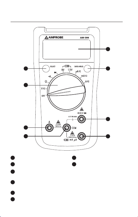
AM-500 Autoranging Mulitmeter
AM-500-EUR DIY-PRO Digital Multimeter
4
7
8
1
32
5
6
1
LCD Display
2
SELECT Button
5
Input Terminal for voltage, diode, resistance and
continuity measurement
6
Input Terminal for battery test and AC/DC mA or μA
measurement
7
Input Terminal for AC/DC A measurement to10A
8
COM (return) terminal for all measurements
3
DATA HOLD Button
4
Rotary Switch
Page 7
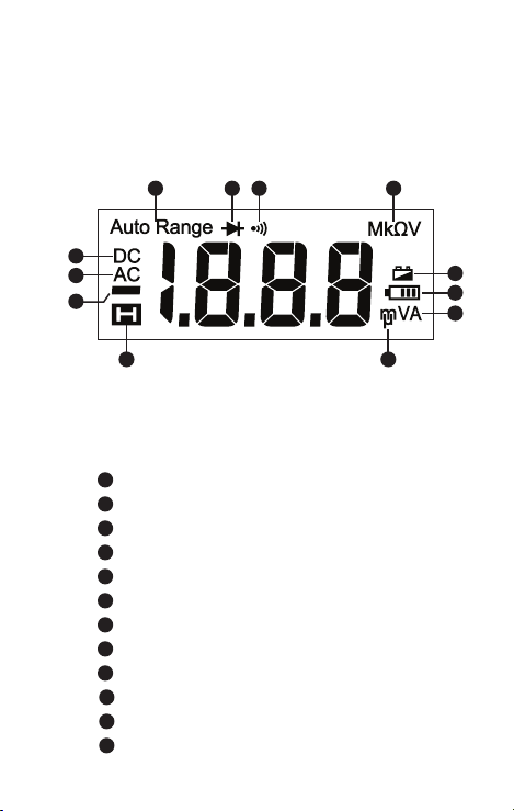
Screen Display
1 6 7
2
3
4
5
1
The Meter selects the range with best resolution
2
Direct Current
3
Alternate Current
4
Negative reading
5
Data hold
6
Diode test
7
Continuity test
8
Measurement units for resistance test
9
Measurement units for voltage test
10
Measurement units for current test
11
Low battery indicator
12
Battery Test
8
11
12
10
9
Page 8

CONTENTS
SYMBOLS ............................................................................ 2
SAFETY INFORMATION ......................................................2
UNPACKING AND INSPECTION ..........................................4
FEATURES ............................................................................4
MAKING MEASUREMENT .................................................. 5
Rotary Switch Positions .................................................. 5
SELECT Button ................................................................ 6
DATA HOLD Button ........................................................ 6
Auto Power OFF ............................................................. 6
Measuring AC and DC Voltage ...................................... 6
Measuring Resistance .................................................... 7
Measuring Continuity .................................................... 7
Measuring Diode ............................................................ 8
Battery Test .....................................................................8
Measuring AC and DC Current ...................................... 9
SPECIFICATION ....................................................................10
MAINTENANCE AND REPAIR .............................................14
BATTERY AND FUSE REPLACEMENT .................................. 15
1
Page 9
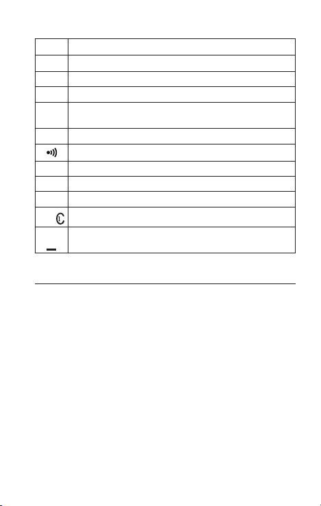
SYMBOLS
Caution ! Risk of electric shock.
Caution! Refer to the explanation in this Manual
Alternating Current (AC)
Direct Current (DC)
The equipment is protected by double insulation
or reinforced insulation
Earth (Ground)
Audible tone
Battery
Complies with European Directives
Conforms to relevant Australian standards
Canadian Standards Association (NRTL/C)
Do not dispose of this product as unsorted
municipal waste. Contact a qualified recycler.
SAFETY INFORMATION
The Meter complies with:
IEC/EN 61010-1 3rd Edition, UL61010-1 2nd Ed. and CAN/
CSA-C22.2 No. 61010-1-04 + CSA Update No.1: 2008 to
Category III 600 Volts, Pollution degree 2
IEC/EN 61010-2-030
IEC/EN 61010-2-31 for test leads
EMC IEC/EN 61326-1
“This product has been tested to the requirements of
CAN/CSA-C22.2 No. 61010-1, second edition, including
Amendment 1, or a later version of the same standard
incorporating the same level of testing requirements”.
Measurement Category III (CAT III) is for measurements
performed in the building installation. Examples are
measurements on distribution boards, circuit- breakers,
wiring, including cables, bus-bars, junction boxes,
2
Page 10

switches, socket-outlets in the fixed installation, and
equipment for industrial use and some other equipment,
for example, stationary motors with permanent
connection to the fixed installation.
CENELEC Directives
The instruments conform to CENELEC Low-voltage
directive 2006/95/EC and Electromagnetic compatibility
directive 2004/108/EC
Warning: Read Before Using
• To avoid possible electrical shock or personal injury,
follow these instructions and use the Meter only as
specified in this manual.
• Do not use the Meter or test leads if they appear
damaged, or if the Meter is not operating properly.
If in doubt, have the Meter serviced.
• Always use the proper function and range for
measurements.
• Before rotating the function range selection switch,
disconnect test probe from circuit under test.
• Verify the Meter’s operation by measuring on a
known voltage source.
• Do not apply more than the rated voltage, as
marked on the Meter, between the test probe or
between any test probe and earth ground.
• Use the Meter with caution for voltages above 30
Vac rms, 42 Vac peak, or 60 Vdc. These voltages pose
electrical shock hazards.
• Disconnect circuit power and discharge all high-
voltage capacitors before testing resistance.
• Do not use the Meter around explosive gas or vapor.
• When using the test leads, keep your fingers behind
the finger guards.
• Remove test leads from the Meter before opening
the Meter case or battery door.
• if the meter is used in a manner not specified in
the users manual, the protection provided by the
equipment may be impaired
3
Page 11

UNPACKING AND INSPECTION
Your shipping carton should include:
1 AM-500 or AM-500-EUR Multimeter
1 Pair of test leads
2 1.5V alkaline AAA battery (installed)
1 Users manual
1 Carrying case
If any of the items are damaged or missing, return
the complete package to the place of purchase for an
exchange.
FEATURES
Easy to use digital multimeter designed for the
homeowner or DIY enthusiast. Install, troubleshoot or
repair light fixtures, fans, appliances, or automotive
electrical problems with easy and safety of a CAT III 600V
rated product. Check for voltage in electrical sockets,
extension cords, batteries and other electrical circuits. Let
the power of a professional Amprobe multimeter keep
you safe and help you solve all your electrical challenges.
• Measurements: Voltage up to 600V AC/DC, AC/DC
Current and Resistance
• Audible continuity
• Diode Test
• Data hold
• Auto power off
• Low battery warning
• Safety: CAT III 600V
4
Page 12
MAKING MEASUREMENT
1. Use the proper function and range for
measurements.
2. To avoid possible electrical shock, personal injury or
damages to the Meter, disconnect circuit power and
discharge all high-voltage capacitors before testing
resistance and diode.
3. Connecting test leads:
• Connect the common (COM) test lead to the circuit
before connecting the live lead.
• After measurement, remove live lead before
removing the common (COM) test lead from the
circuit.
4. Symbol “OL” is displayed on LCD when the
measurement is out of range.
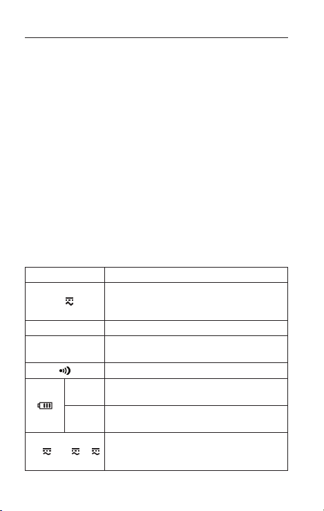
Rotary Switch Positions
Switch Position Measurement Function
AC or DC voltage measurement (use
SELECT button for switching to AC
or DC).
Resistance measurement
Voltage measurement of diode PN
junction
Continuity measurement
For measurement of dry batteries of
9V
not exceeding 15Vdc
For measurement of dry batteries of
1.5V
not exceeding 2Vdc
AC or DC current measurement (use
SELECT button for switching to AC
or DC).
μA
V
mA A
5
Page 13
Press to select altemate measurement
SELECT
Button
functions on the rotary switch.
DATA
Display freezes present reading
HOLD
SELECT Button
Press the yellow SELECT button to select alternate
measurement functions on the rotary switch.
DATA HOLD Button
Press DATA HOLD button to freeze present reading on
display. Press again to resume normal operation.
Auto Power OFF
Auto power off: approx. 15 minutes.
When the Meter is in auto power off mode, press SELECT
or DATA HOLD button to resume normal operation.
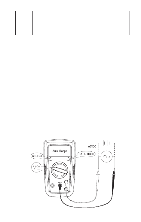
Measuring AC and DC Voltage
Press SELECT button to switch to DC voltage
measurement function.
Do not apply on a voltage source higher than
AC/DC 600V.
6
Page 14
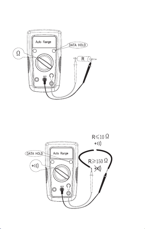
Measuring Resistance
Disconnect circuit power and discharge all
high-voltage capacitors before testing resistance.
Note: On a higher resistance measurement (>1MΩ), the
measurement may take a few seconds to get stable reading.
Measuring Continuity
Disconnect circuit power and discharge all high-
voltage capacitors before testing continuity.
7
Page 15
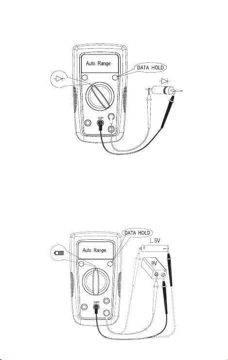
Measuring Diode
Disconnect circuit power and discharge all high-
voltage capacitors before testing diode.
Battery Test
Applying a voltage source or incorrect battery type
under battery test may cause personal Injury or damage
to the Meter.
Battery 1.5V range is for dry battery not exceeding 2Vdc.
The resistance load is around 30Ω.
Battery 9V range is for dry battery not exceeding 15Vdc.
The resistance load is around 1KΩ.The resistance load is
around 1KΩ.
8
Page 16
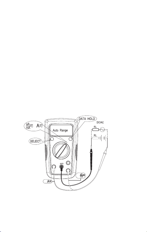
Measuring AC and DC Current
Press SELECT button for switching to DC current
measurement function.
To avoid personal injury or damage to the Meter:
1. Do not attempt to make an in-circuit current
measurement when the open-circuit potential to
earth ground exceeding 600 V.
2. Switch to proper function and range for your
measurement.
3. Do not place the test probe in parallel with a circuit
when the test leads are connected to the current
terminals.
4. Connect the test leads to the correct input A/mA μA
current terminal and to the circuit before powering
the circuit under test.
5. After measurement, switching OFF the circuit’s
power before removing test leads from the circuit.
or
for
for
For current range from 8-10A, do not measure current
for more than one (1) minute. Wait for 10 minutes
before taking another measurement.
9
Page 17

SPECIFICATION
Ambient temperature: 23°C ±5°C (73.4°F ±9°F)
Relative temperature: ≤ 75%
Accuracy: ±(% of reading + digits)
Maximum voltage between input terminal and earth
ground: AC 600Vrms or DC 600V
Fuse for mA μA input:
0.5A H 660V fast-fuse, 6.3x32mm (AM-500)
0.5A H 700V fast-fuse, 6.3x32mm (AM-500-EUR)
Fuse for 10A input:
10A H 660V fast-fuse, 6.3x32mm (AM-500)
10A H 600V fast-fuse, 6x25mm (AM-500-EUR)
Maximum display: 1999, updates 2 to 3/sec
Over-range indication: OL
Range: Automatic
Altitude: Operating ≤ 2000m
Operating temperature: 0°C ~ +40°C (32°F ~ 104°F)
Relative humidity: 0°C ~ +30°C (32°F ~ 86°F) ≤ 75%; +30°C
~ +40°C (86°F ~ 104°F) ≤ 50%
Storage temperature: -10°C ~ +50°C (14°F ~ 122°F)
Electromagnetic compatibility: In an RF filed of 1V/m =
Specified accuracy ±5%
Battery: 2 x 1.5V AAA alkaline battery or equivalent
Low battery indication:
Dimensions (L x W x H): 150 mm x 83 mm x 40 mm (5.9 in
x 3.3 in x 1.6 in)
Weight: Approx. 290g (0.64lb) with batteries installed
10
Page 18

1. DC Voltage Measurement
Range Resolution Accuracy
200.0mV 0.1mV ±(0.8%+3dgt)
2.000V 1mV
±(0.8%+1dgt)20.00V 10mV
200.0V 100mV
600V 1V ±(1.0%+3dgt)
Input impedance: around 10M; (Input impedance > 3G
for DC 200mV range)
Overload protection: 600VDC or AC rms
2. AC Voltage Measurement
Range Resolution Accuracy
2.000V 1mV
±(1.0%+3dgt)20.00V 10mV
200.0V 100mV
600V 1V ±(1.2%+3dgt)
Input impedance: around 10M
Frequency response: 45Hz ~ 400Hz
Overload protection: 600VDC or AC rms
3. Resistance Measurement
Range Resolution Accuracy
200.0Ω 0.1Ω
2.000kΩ 1Ω
200.0kΩ 100Ω
2.000MΩ 1kΩ ±(1.2%+2dgt)
20.00MΩ 10kΩ ±(1.5%+5dgt)
±(1.2%+5dgt) at ≤5Ω
±(1.2%+3dgt) at >5Ω
±(1.0%+2dgt)20.00kΩ 10Ω
11
Page 19

200Ω range: Measured value = (Measured display value)
– (Short-circuiting value of probe)
Open circuit voltage: around 0.5V
Overload protection: 600V
4. : Continuity : Diode measurement
Range Resolution Accuracy
Open circuit voltage is around 0.5V.
Resistance >150Ω, buzzer will not
0.1Ω
Overload protection: 600V
1mV
sound.
Resistance ≤10Ω, buzzer will sound.
11 < Resistance < 150.........Not
Specified.
Open-circuit voltage is around 1.5V.
Normal voltage is around 0.5V to
0.8V for silicon PN junction.
5. Battery Test
Range Resolution Accuracy
1.5V
9V
Overload protection:
10mV ±(10%+3dgt)
F1 fuse, 0.5A H 660V fast-fuse, 6.3x32mm (AM-500)
F1 fuse, 0.5A H 700V fast-fuse, 6.3x32mm (AM-500-EUR)
For 1.5V range: Load resistance is around 30Ω.
For 9V range: Load resistance is around 1kΩ.
12
Page 20
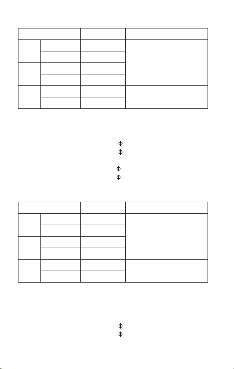
6. DC Current Measurement
Range Resolution Accuracy
200.0μA 0.1μA
μA
2000μA 1μA
20.00mA 10μA
mA
200.0mA 0.1mA
2.000A 1mA
A
10.00A 10mA
Overload protection:
±(1.0%+2dgt)
±(1.2%+3dgt)
mA /μA input:
F1 fuse, 0.5A H 660V fast-fuse, 6.3x32mm (AM-500)
F1 fuse, 0.5A H 700V fast-fuse, 6.3x32mm (AM-500-EUR)
10 A input:
F2 fuse, 10A H 660V fast-fuse, 6.3x32mm (AM-500)
F2 fuse, 10A H 600V fast-fuse, 6x25mm (AM-500-EUR)
7. AC Current Measurement
Range Resolution Accuracy
200.0μA 0.1μA
μA
2000μA 1μA
20.00mA 10μA
mA
200.0mA 0.1mA
2.000A 1mA
A
10.00A 10mA
Frequency response: 45Hz ~ 400Hz
Overload protection:
±(1.2%+2dgt)
±(1.5%+3dgt)
mA /μA input:
F1 fuse, 0.5A H 660V fast-fuse, 6.3x32mm (AM-500)
F1 fuse, 0.5A H 700V fast-fuse, 6.3x32mm (AM-500-EUR)
13
Page 21

10 A input:
F2 fuse, 10A H 660V fast-fuse, 6.3x32mm (AM-500)
F2 fuse, 10A H 600V fast-fuse, 6x25mm (AM-500-EUR)
MAINTENANCE AND REPAIR
If the Meter fails to operate, check battery, test leads, etc.,
and replace as necessary.
Double check the followings:
1. Replace the fuse or battery if the meter does not
work.
2. Review the operating instructions for possible
mistakes in operating procedure.
Except for the replacement of the battery, repair of the
meter should be performed only by an Authorized Service
Center or by other qualified instrument service personnel.
The front panel and case can be cleaned with a mild
solution of detergent and water.
Apply sparingly with a soft cloth and allow to dry
completely before using. Do not use aromatic
hydrocarbons, Gasoline or chlorinated solvents for
cleaning.
14
Page 22
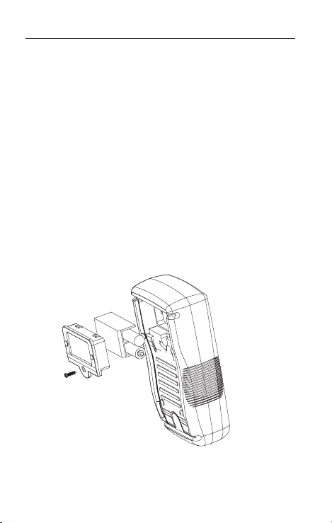
BATTERY AND FUSE REPLACEMENT
WARNING
To avoid shock, injury, or damage to the Meter:
Disconnect test leads before opening case.
Use ONLY fuses with the amperage, interrupt,
voltage, and speed ratings specified.
Replacing BATTERY follow below steps:
1. Disconnect the test lead probe from measuring
circuit.
2. Turn the Meter to OFF position.
3. Remove the screws from the battery cover and
open the battery cover
4. Remove the batteries and replace with two
1.5V Alkaline Batteries (AAA) or equivalent. Pay
attention to the polarity signs.
5. Put the battery cover back and re-fasten the screw.
Battery: 1.5V Alkaline Batteries (AAA) or equivalent
15
Page 23
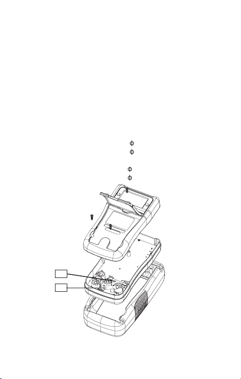
Replacing FUSE follow below steps:
1. Disconnect the test lead probe from measuring
circuit.
2. Turn the Meter to OFF position and remove the
holster.
3. Remove the screws from the enclosure and open
the enclosure.
4. Remove the broken fuse and replace with new
specified fuse.
5. Put the enclosure back and re-fasten the screw.
Fuse:
mA /μA input:
F1 fuse, 0.5A H 660V fast-fuse,
6.3x32mm (AM-500)
F1 fuse, 0.5A H 700V fast-fuse, 6.3x32mm (AM-500-EUR)
10 A input:
F2 fuse, 10A H 660V fast-fuse, 6.3x32mm (AM-500)
F2 fuse, 10A H 600V fast-fuse, 6x25mm (AM-500-EUR)
F1
F2
16
Page 24

 Loading...