

Page 1

Technical Note
s
o
l
e
a
o
e
i
o
a
F
d
ReFlex Power™ Fault Protection Groups
Document No. M380595-TN Rev A • 01/08/09
PURPOSE
Establish and configure Fault Protection Group s for the Elgar
ReFlex Power™ system. Fault Protection Groups are
presently available for DC Power Modules with Firmware
Version 2.000.018xi or higher, with Control ler Module
BACKGROUND
The ReFlex PowerTM system presently includes fault
monitoring and shutdown at the individual power module level,
and through the ReFlex Power
the outputs (Remote Inhibit) of all power module s contain ed
within a system. All ReFlex Power
Module Enable (ENA) signal that allows the user to enable or
disable each power module individually with an external signal
or relay contact closure.
TM
Controller module to inhibit
TM
power modules include a
Firmware Version 2.001.029xf or higher. Fault Protection
Group functionality will be added to future releases of firmware
for AC and Load Modules.
Each DC power module also includes a Trigger Input (T RIGIN) and Trigger Output (TRIG-OUT) si gnal on the front p anel
Interface connector for imple menting preci se timing function s
based upon internal and/or extern al events. List mode
sequences may be preprogrammed to ex ecute upon receipt of
trigger signals. The Controller module al so includes fou r bidirectional Digital Input/Output signals (DIG0-I/O through
DIG3-I/O) that are passed through the Co ntroller module to the
ReFlex Power
TM
mainframe backplane for processing by DC
power modules.
FAULT PROTECTION GROUPS
Fault Protection Groups provide additional capa bility to group
and to shutdown DC power modules through the po wer
module Enable Input and Trigger Output signals. The ability to
TERMS AND DEFINITIONS
ENA Enable The Enable signal is an input on ReFlex PowerTMpower module
Interface connector (ENA = Pin 1, ENA-RTN = Pin 6) that enables
disables the power module outputs. The Enable signal is internal
pulled up to +5VDC with a 10K ohm resistor. To enable the modul
the signal is pulled low (<= 0.5VDC) with respect to ENA RTN sign
this may also be accomplished by shorting Pins 1 and 6.
TRIG-OUT Trigger Output Signal output on ReFlex Power
(TRIG-OUT = Pin 2, TRIG-OUT-RTN = Pin 7) that produce a
external trigger signal. The Trigger output signal is TTL compatibl
Vol <= 0.3VDC @ 1mA, Voh >= 4.13VDC @ 1mA. Trigger latency
<= 5uS. Trigger outputs may be positive leading edge asserted
negative leading edge asserted.
MODF Module Fault Output The Trigger Output (TRIG-OUT) signals on the power modul
Interface connector may be reconfigured via a software command
a Module Fault (MODF) output signal (MODF-OUT = Pin 2, MOD
OUT-RTN = Pin 7) to assert a latched output upon detection of a
internal fault condition.
create fault groups through these signals p rovides increa sed
flexibility and reconfigurability to meet various user
requirements.
TM
power modules’ Interface connect
SCPI Standard Commands for
Programmable Instruments
9250 Brown Deer Road, Sa n Diego CA 92121 • Tel: 858-4 50-008 5 • Fax: 858-458- 0267 • e mail: sal es@progra mmablep ower.com • Web: www.programm ablepow er.com
©2009 AMETEK Programmable Pow er, Inc. • All rights reserv ed. • AME TEK is a tr ademark o f AMETEK, Inc .
Developed by the SCPI Consortium as a standard set of comman
to control test and measurement devices in in strumentation syst ems.
1 of 4
Page 2
Technical Note
ReFlex Power™ Fault Protection Groups
Document No. M380595-TN Rev A • 01/08/09
THEORY OF OPERATION
Fault Protection Groups may be implemented by external user
wiring through the ReFlex Power
TM
front panel Interface
connector on each DC power module. The flexibl e user implementation allows the creation of three basi c fault group types:
TM
• Single Fault Protection Group: All ReFlex Power
DC
modules externally interconnected to provide imme diate
shut down all DC power module outputs upon a fault
condition in any DC power module.
• Multiple Independent Fault Protection Groups: Groups
of ReFlex Power
TM
DC modules independently
interconnected to shut down of all DC power module
USER APPLICATION WIRING
outputs within each independent group without affecting the
functions of other independent groups.
• Multiple Dependent Fault Protection Groups: Using an
external resistor and Schottky Diode the us er may create
dependent Fault Protection Groups wherein a fault in Group
A will shut down all DC power modules in Group A and
Group B, but a fault in Group B will not affect the module
outputs in Group A. The following diagram depicts t he
external wiring required to create each of these Fault
Protection Group types.
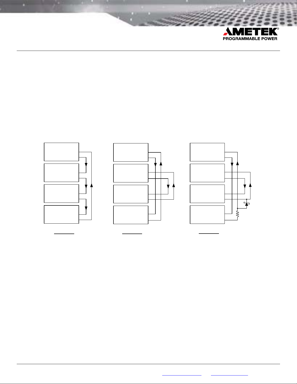
Module 1
MODF-OUT
Module 2
MODF-OUT
Module 3
MODF-OUT
Module 4
MODF-OUT
Example 1 Example 2
Single (System)
Fault G roup
ENA
ENA
ENA
ENA
1
2
1
2
1
2
1
2
Module 1
ENA
MODF-OUT
Module 2
ENA
MODF-OUT
Module 3
ENA
MODF-OUT
Module 4
ENA
MODF-OUT
Multiple, Inde p e n d e n t
Fault G r oups
Example 1 depicts the MODF-OUT signal of Module 1
connected to the ENAble input of Module 2. This method is
repeated from module-to-module until the final module MODFOUT signal is connected back to the ENAble input of Module
1. A fault condition on any module will assert the MODF-OUT
signal to the next power module ENAble lin e, causing it to de assert its enable (disable) and shutdown the module output.
This chain reaction quickly disables the outputs of all DC
power modules within the system. Since the ENAble inputs
are de-asserted on all other modules in the chain, only the
module with the fault that started the sequence will indicate a
fault condition. All connected modules shall remain latched in
shutdown until the original fault condition is cleared.
1
2
1
2
1
2
1
2
Module 1
MODF-OUT
Module 2
MODF-OUT
Module 3
MODF-OUT
Module 4
MODF-OUT
Example 3
Multip le, D e pen d e nt
Fault G r o ups
ENA
ENA
ENA
ENA
1
2
1
2
1
2
1
R
2
TBD
Example 2 depicts two independent fault groups connected in
a similar fashion. Module 1 and Module 4 will shutdown when
either experiences a fault condition. Likewise, Modul e 2 and
Module 3 will shutdown when either experiences a fault
condition. However, the fault group co mprised of Mod ule 1
and Module 4 will continue to operate inde pendently of a fault
condition with Module 2 and Module 3.
In Example 3, if either Module 2 or 3 faults off, then Modules 1
and 4 will also shutdown; however, if either Module 1 o r 4
faults off, then Modules 2 & 3 will not be shut down
9250 Brown Deer Road, Sa n Diego CA 92121 • Tel: 858-4 50-008 5 • Fax: 858-458- 0267 • e mail: sal es@progra mmablep ower.com • Web: www.programm ablepow er.com
©2009 AMETEK Programmable Pow er, Inc. • All rights reserv ed. • AME TEK is a tr ademark o f AMETEK, Inc .
2 of 4
Page 3

Technical Note
ReFlex Power™ Fault Protection Groups
Document No. M380595-TN Rev A • 01/08/09
The following diagram depicts all the requi red conn ections to
implement an entire system fault group. An external Panic
Switch is included in the diagram to define the
interconnections for an operator comm anded shutdo wn. In
this application, the Panic Switch sh all allow all interco nnected
modules to follow the function of the switch. Since no fault has
been reported, the user may use this feature to command all
power modules off.
Controller Interface
Interface Connector
MODF/TRIG-OUT-RTN
Connector
RI
RI-RTN
DFI
DFI-RTN
DIG0-I/O 4
DIG1-I/O
DIG2-I/O
DIG3-I/O
DIG-I/O-RTN
PWR ON
PWR ON-RTN
CHAS-GND
Power Module 1
ENA
ENA-RTN
MODF/TRIG-OUT
TRIG-IN
TRIG-IN-RTN
CHAS-GND
1
9
2
10
12
5
13
6
3
11
8
1
6
2
7
3
8
5
An external Interlock Switch is shown connected to the
Remote Inhibit pins of the Controller module to prevent turning
on power module outputs until conditions a re safe. Fi nal ly , the
Discrete Fault Indicator (DFI) and Powe r On (P WR ON) output
signals of the Controller are shown illuminating indicators in
the user space.
User Space / Interface Test Adapter
Interlock
T/P
T/P
T/P
Panic
Switch
T/P
T/P
T/P
Trigger
Input
Switch
T/P
T/P
+V
Fault
Digital
I/O
Lines
T/P
+V
Power
Power Module 2
Interface Connector
ENA
ENA-RTN
MODF/TRIG-OUT
MODF/TRIG-OUT-RTN
TRIG-IN
TRIG-IN-RTN
CHAS-GND
Power Module
Interface Connector
ENA
ENA-RTN
MODF/TRIG-OUT
MODF/TRIG-OUT-RTN
TRIG-IN
TRIG-IN-RTN
CHAS-GND
T/P
1
6
T/P
2
7
T/P
3
8
Trigger
Input
5
n
T/P
1
6
T/P
2
7
T/P
3
8
Trigger
Input
5
NOTE:
T/P = Twisted Pair
= Shield
Detailed Fault Protection Group Wiring Diagram
9250 Brown Deer Road, Sa n Diego CA 92121 • Tel: 858-4 50-008 5 • Fax: 858-458- 0267 • e mail: sal es@progra mmablep ower.com • Web: www.programm ablepow er.com
©2009 AMETEK Programmable Pow er, Inc. • All rights reserv ed. • AME TEK is a tr ademark o f AMETEK, Inc .
3 of 4
Page 4

Technical Note
ReFlex Power™ Fault Protection Groups
Document No. M380595-TN Rev A • 01/08/09
FAULT PROTECTION GROUP SCPI COMMANDS
The ReFlex PowerTM MODF signal requires the follo wing SCPI
command to setup or preprogram power module s to execute a
shutdown on individual faults or when the ENAble input is
SCPI Command Description
OUTP<n>:MODFault bval Establish on module n, bval = On, that Trig Out is in MODule Fault
output mode, bval = Off, normal trigger mode (Power on default).
OUTP<n>:MODFault? Query if Trig Out is configured for MODF operation on module n.
When a Fault occurs, if the cause of the fault is external to the
RFP system, the user will need to take corrective action to
remove the cause of the fault. Only the Module that cau sed
the fault will show a fault other than GroupFault if the fault wa s
triggered from a Series or Parallel Group. If the fault was
caused by a non-group module then its fault indicator will be
illuminated. For example, if the fault was caused by an OCP,
and the Current protection limit turned out to be too low, then
the OCP limit would need to be modified. To resume
deasserted. For additional details of ReFlex PowerTM SCPI
programming commands please refer to the Programming
Manual, M380056-03.
operation of the fault group, issue the following comman d
sequence: *CLS<n> to the module that caused the fault that
brought down the group; this will de-assert the MODF signal,
and then issue OUTP<n>:STATE 1 command s to the
modules/Group Masters in the proper o rder to bri ng up the
voltages in proper sequence. A system Reset (*RST) will
clear all Fault Protection Groups restore all modules to poweron default conditions. Fault Protection Groups must be
reprogrammed after a syste m rese
FAULT PROTECTION GROUP TIMING CHARACTERISTICS
The Module Fault Output signal is generated in VHDL to
ensure fast response to any reported fault condition with a
latency of 500 nanoseconds maximum from module-tomodule. The Oscillograph below shows two Re Flex Power
Module 1 Fault
Module 2
Deasserted
modules MODF signals on Ch. 1 and 3, and output signals on
Ch. 2 and 4, respectively. A fault condition on one module
immediately de-asserts the ENAble input to the second
TM
module, resulting in both modules shutting down.
Module 1 Output Shut Down
Module 2 Output Shut Down
9250 Brown Deer Road, Sa n Diego CA 92121 • Tel: 858-4 50-008 5 • Fax: 858-458- 0267 • e mail: sal es@progra mmablep ower.com • Web: www.programm ablepow er.com
©2009 AMETEK Programmable Pow er, Inc. • All rights reserv ed. • AME TEK is a tr ademark o f AMETEK, Inc .
4 of 4
 Loading...