

Page 1

ReFlex Power™
Programming Manual
M380056-03 Rev M www.programmablepower.com
Page 2

Page 3

Page 4

Page 5

About AMETEK
AMETEK Programmable Power, Inc., a Division of AMETEK, Inc., is a global leader in the design and
manufacture of precision, programmable power supplies for R&D, test and measurement, process control, power
bus simulation and power conditioning applications across diverse industrial segments. From bench top supplies
to rack-mounted industrial power subsystems, AMETEK Programmable Power is the proud manufacturer of Elgar,
Sorensen, California Instruments and Power Ten brand power supplies.
AMETEK, Inc. is a leading global manufacturer of electronic instruments and electromechanical devices with
annualized sales of $2.5 billion. The Company has over 11,000 colleagues working at more than 80
manufacturing facilities and more than 80 sales and service centers in the United States and around the world.
Trademarks
AMETEK is a registered trademark of AMETEK, Inc.
Other trademarks, registered trademarks, and product names are the property of their respective owners and are
used herein for identification purposes only.
Notice of Copyright
ReFlex Power™ Programming Manual
© 2007-2014 AMETEK Programmable Power, Inc. All rights reserved.
Exclusion for Documentation
UNLESS SPECIFICALLY AGREED TO IN WRITING, AMETEK PROGRAMMABLE POWER, INC.
(“AMETEK”):
(a) MAKES NO WARRANTY AS TO THE ACCURACY, SUFFICIENCY OR SUITABILITY OF ANY TECHNICAL OR
OTHER INFORMATION PROVIDED IN ITS MANUALS OR OTHER DOCUMENTATION.
(b) ASSUMES NO RESPONSIBILITY OR LIABILITY FOR LOSSES, DAMAGES, COSTS OR EXPENSES, WHETHER
SPECIAL, DIRECT, INDIRECT, CONSEQUENTIAL OR INCIDENTAL, WHICH MIGHT ARISE OUT OF THE USE OF
SUCH INFORMATION. THE USE OF ANY SUCH INFORMATION WILL BE ENTIRELY AT THE USER’S RISK, AND
(c) REMINDS YOU THAT IF THIS MANUAL IS IN ANY LANGUAGE OTHER THAN ENGLISH, ALTHOUGH STEPS
HAVE BEEN TAKEN TO MAINTAIN THE ACCURACY OF THE TRANSLATION, THE ACCURACY CANNOT BE
GUARANTEED. APPROVED AMETEK CONTENT IS CONTAINED WITH THE ENGLISH LANGUAGE VERSION,
WHICH IS POSTED AT WWW.PROGRAMMABLEPOWER.COM.
Date and Revision
May 2014 revision L
Part Number
M380056-03
Contact Information
Telephone: 800 733 5427 (toll free in North America)
858 450 0085 (direct)
Fax: 858 458 0267
Email: sales.ppd@ametek.com
service.ppd@ametek.com
Web: www.programmablepower.com
M380056-03 Rev M i
Page 6

This page intentionally left blank.
ii M380056-03 Rev M
Page 7
Elgar ReFlex Power™ Contents
Important Safety Instructions
Before applying power to the system, verify that your product is configured properly for your particular application.
WARNING
WARNING
Only qualified personnel who deal with attendant hazards in power supplies, are allowed to perform installation and
servicing.
Ensure that the AC power line ground is connected properly to the Power Rack input connector or chassis.
Similarly, other power ground lines including those to application and maintenance equipment must be grounded
properly for both personnel and equipment safety.
Always ensure that facility AC input power is de-energized prior to connecting or disconnecting any cable.
In normal operation, the operator does not have access to hazardous voltages within the chassis. However,
depending on the user’s application configuration, HIGH VOLTAGES HAZARDOUS TO HUMAN SAFETY may be
normally generated on the output terminals. The customer/user must ensure that the output power lines are labeled
properly as to the safety hazards and that any inadvertent contact with hazardous voltages is eliminated.
Guard against risks of electrical shock during open cover checks by not touching any portion of the electrical
circuits. Even when power is off, capacitors may retain an electrical charge. Use safety glasses during open cover
checks to avoid personal injury by any sudden component failure.
Neither AMETEK Programmable Power Inc., San Diego, California, USA, nor any of the subsidiary sales
organizations can accept any responsibility for personnel, material or inconsequential injury, loss or damage that
results from improper use of the equipment and accessories.
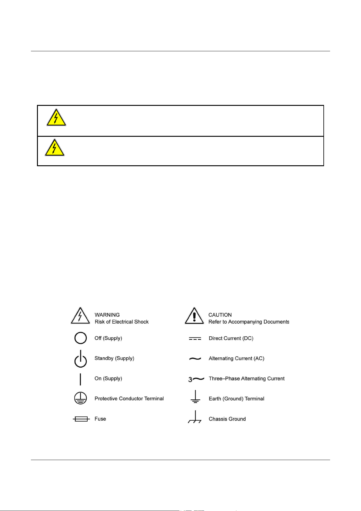
Hazardous voltages may be present when covers are removed. Qualified personnel
must use extreme caution when servicing this equipment. Circuit boards, test points,
and output voltages also may be floating above (below) chassis ground.
The equipment used contains ESD sensitive parts. When installing equipment, follow
ESD Safety Procedures. Electrostatic discharges might cause damage to the
equipment.
SAFETY SYMBOLS
M380056-03 Rev L iii
Page 8

This page intentionally left blank.
iv M380056-03 Rev M
Page 9

Elgar ReFlex Power™ Contents
Product Family: ReFlex Power™
Warranty Period: One Year
WARRANTY TERMS
AMETEK Programmable Power, Inc. (“AMETEK”), provides this written warranty covering the Product stated
above, and if the Buyer discovers and notifies AMETEK in writing of any defect in material or workmanship within
the applicable warranty period stated above, then AMETEK may, at its option: repair or replace the Product; or
issue a credit note for the defective Product; or provide the Buyer with replacement parts for the Product.
The Buyer will, at its expense, return the defective Product or parts thereof to AMETEK in accordance with the
return procedure specified below. AMETEK will, at its expense, deliver the repaired or replaced Product or parts
to the Buyer. Any warranty of AMETEK will not apply if the Buyer is in default under the Purchase Order
Agreement or where the Product or any part thereof:
•
is damaged by misuse, accident, negligence or failure to maintain the same as specified or
required by AMETEK;
•
is damaged by modifications, alterations or attachments thereto which are not authorized
by AMETEK;
•
is installed or operated contrary to the instructions of AMETEK;
•
is opened, modified or disassembled in any way without AMETEK’s consent; or
•
is used in combination with items, articles or materials not authorized by AMETEK.
The Buyer may not assert any claim that the Products are not in conformity with any warranty until the Buyer has
made all payments to AMETEK provided for in the Purchase Order Agreement.
PRODUCT RETURN PROCEDURE
1. Request a Return Material Authorization (RMA) number from the repair facility (must be done in the
country in which it was purchased):
•
In the USA, contact the AMETEK Repair Department prior to the return of the product to
AMETEK for repair:
Telephone: 800-733-5427, ext. 2295 or ext. 2463 (toll free North America)
858-450-0085, ext. 2295 or ext. 2463 (direct)
•
Outside the United States, contact the nearest Authorized Service Center (ASC). A full
listing can be found either through your local distributor or our website,
www.programmablepower.com, by clicking Support and going to the Service Centers tab.
2. When requesting an RMA, have the following information ready:
•
Model number
•
Serial number
•
Description of the problem
NOTE: Unauthorized returns will not be accepted and will be returned at the shipper’s expense.
NOTE: A returned product found upon inspection by AMETEK, to be in specification is subject to an evaluation
fee and applicable freight charges.
M380056-03 Rev L v
Page 10

This page intentionally left blank.
vi M380056-03 Rev M
Page 11

Elgar ReFlex Power™ Contents
CONTENTS
1.
1.1
1.2
1.3
REMOTE PROGRAMMING OVERVIEW ................................. 15
System Level Introduction ............................................................................. 15
Features and Functions ................................................................................ 15
ReFlex Power™ IVI-COM drivers ................................................................. 15
1.4
2.
2.1
2.2
2.3
2.4
2.5
1.3.1 IVI-COM Drivers Installation ........................................................................... 16
1.3.2 IVI-COM Drivers Help .................................................................................... 16
ReFlex Power™ FIRMWARE COMPATIBILITY ........................................... 17
1.4.1 Firmware V3 Differences ................................................................................ 17
CONTROLLER MODULE REMOTE PROGRAMMING ............ 19
Introduction ................................................................................................... 19
Features and Functions ................................................................................ 19
Power-On Conditions and Address Configuration ......................................... 20
Ethernet Configuration and Remote Programming ....................................... 20
2.4.1 Ethernet Connection Requirements................................................................ 20
2.4.2 Ethernet Setup Procedure .............................................................................. 21
2.4.3 Launching Ethernet Communication ............................................................... 22
ReFlex Power™ Ethernet Interface ............................................................... 24
2.5.1 Home Page ................................................................................................... 24
2.5.2 LOGIN Screen ............................................................................................... 25
2.5.3 IP Configuration ............................................................................................. 26
2.5.4 Security Page ................................................................................................ 29
2.5.5 Modules Page ................................................................................................ 32
M380056-03 Rev L vii
Page 12

2.6
Launching Control Communication ............................................................... 33
2.6.1 Module Location Identification (Address) ........................................................ 35
2.6.2 Communication with the System .................................................................... 36
2.7
SCPI Command Operation ........................................................................... 36
2.7.1 Error/Event Queue ......................................................................................... 36
2.8
LXI™ and SCPI Conformance Information.................................................... 37
2.8.1 Parameter Definitions .................................................................................... 38
2.8.2 Numeric Data Dimensional Units .................................................................... 38
2.8.3 Conventions .................................................................................................. 38
2.8.4 Query Syntax ................................................................................................. 39
2.9
Common SCPI Commands ........................................................................... 40
2.10 EIB SCPI Commands.................................................................................... 41
2.10.1 EIB SCPI Command Summary ...................................................................... 41
2.10.2 EIB SCPI Command Reference ..................................................................... 41
2.11 SYSTEM:NETWORK SCPI Commands........................................................ 42
2.11.1 SYSTEM:NETWORK SCPI Command Summary ........................................... 42
2.11.2 SYSTEM:NETWORK SCPI Command Reference .......................................... 43
2.13 RFP Service Request.................................................................................... 44
2.13.1 Background ................................................................................................... 44
2.13.2 Theory of Operation ....................................................................................... 45
2.13.3 Event Status Register .................................................................................... 45
2.13.4 Protection Event Register .............................................................................. 45
2.13.5 Register Allocation ......................................................................................... 45
2.13.6 Execution time Operation ............................................................................... 46
2.13.7 SRQ related SCPI Commands ....................................................................... 47
2.13.8 Setting the SRQ bit in the STB, an example ................................................... 49
2.14 Trigger SCPI Commands .............................................................................. 50
2.14.1 TRIGGER SCPI Command Summary ............................................................ 50
2.14.2 TRIGGER SCPI Command Reference ........................................................... 50
2.15 MEMORY SCPI Commands ......................................................................... 51
2.15.1 MEMORY SCPI Command Summary ............................................................ 51
2.15.2 MEMORY SCPI Command Reference ........................................................... 51
viii M380056-03 Rev M
Page 13

3.
3.1
3.2
3.3
3.4
DC MODULE REMOTE PROGRAMMING ............................... 53
Introduction ................................................................................................... 53
Features and Functions ................................................................................ 53
Power-On Conditions .................................................................................... 54
Error Codes .................................................................................................. 54
3.4.1 Error/Event Queue ......................................................................................... 54
3.5
Common SCPI Commands ........................................................................... 56
3.6
CALIBRATION SCPI Commands .................................................................. 57
3.6.1 CALIBRATION SCPI Command Summary ..................................................... 57
3.6.2 CALIBRATION SCPI Command Reference .................................................... 58
3.7
MEASURE SCPI Commands ........................................................................ 59
3.7.1 MEASURE SCPI Command Summary ........................................................... 59
3.7.2 MEASURE SCPI Command Reference .......................................................... 59
3.8
OUTPUT SCPI Commands ........................................................................... 60
3.8.1 OUTPUT SCPI Command Summary .............................................................. 60
3.8.2 OUTPUT SCPI Command Reference ............................................................ 60
3.9
SOURCE SCPI Commands .......................................................................... 62
3.9.1 SOURCE SCPI Command Summary ............................................................. 62
3.9.2 SOURCE SCPI Command Reference ............................................................ 63
3.10 INPUT SCPI Commands ............................................................................... 64
3.10.1 INPUT SCPI Command Summary ................................................................. 64
3.10.2 INPUT SCPI Command Reference ................................................................ 64
3.11 STATUS SCPI Commands ........................................................................... 65
3.11.1 STATUS SCPI Command Summary .............................................................. 65
3.11.2 STATUS SCPI Command Reference ............................................................. 65
3.12 Trigger SCPI Commands and Lists ............................................................... 66
3.12.1 LIST and Trigger Command Operation........................................................... 66
3.13 Software Triggered Setpoints and Ramps .................................................... 78
3.13.1 Volt and Current Software Setpoints Command summary .............................. 78
3.13.2 Voltage and Current Software Ramps Command Summary ........................... 79
3.14 TRIGGER SCPI Commands ......................................................................... 81
3.14.1 TRIGGER SCPI Command Summary ............................................................ 81
3.14.2 Trigger SCPI Command Reference ................................................................ 81
M380056-03 Rev L ix
Page 14

3.15 LIST SCPI Commands .................................................................................. 82
3.15.1 LIST SCPI Command Summary ..................................................................... 82
3.15.2 LIST SCPI Command Reference ................................................................... 82
3.16 DC SYSTEM SCPI Commands..................................................................... 85
3.16.1 DC SYSTEM SCPI Command Summary ........................................................ 85
3.16.2 SYSTEM SCPI Command Reference ............................................................ 85
3.17 Examples of Using the SCPI Commands ...................................................... 86
4.
AC MODULE REMOTE PROGRAMMING ............................... 89
4.1
Introduction ................................................................................................... 89
4.2
Features and Functions ................................................................................ 89
4.3
Power-On Conditions .................................................................................... 90
4.4
Error Codes .................................................................................................. 91
4.4.1 SCPI Error Codes .......................................................................................... 91
4.4.2 Error/Event Queue ......................................................................................... 92
4.5
Common SCPI Commands ........................................................................... 93
4.6
CALIBRATION SCPI Commands .................................................................. 94
4.6.1 CALIBRATION SCPI Command Summary ..................................................... 94
4.6.2 CALIBRATION SCPI Command Reference .................................................... 96
4.7
MEASURE SCPI Commands ........................................................................ 99
4.7.1 MEASURE SCPI Command Summary ........................................................... 99
4.7.2 MEASURE SCPI Command Reference .......................................................... 99
4.8
OUTPUT SCPI Commands ......................................................................... 100
4.8.1 OUTPUT SCPI Command Summary ............................................................ 100
4.8.2 OUTPUT SCPI Command Reference .......................................................... 100
4.9
SOURCE SCPI Commands ........................................................................ 101
4.9.1 SOURCE SCPI Command Summary ........................................................... 101
4.9.2 SOURCE SCPI Command Reference .......................................................... 102
4.10 STATUS SCPI Commands ......................................................................... 106
4.10.1 STATUS SCPI Command Summary ............................................................ 106
4.10.2 STATUS SCPI Command Reference ........................................................... 106
4.11 SYSTEM SCPI Commands ......................................................................... 108
4.11.1 SYSTEM SCPI Command Summary ............................................................ 108
4.11.2 SYSTEM SCPI Command Reference .......................................................... 108
x M380056-03 Rev M
Page 15

4.12 EXAMPLE SCPI COMMANDs to set phase and parallel groups ................. 108
4.12.1 Examples Creating a Phase Group .............................................................. 108
4.12.2 Example creating a Parallel Group ............................................................... 109
5.
LOAD MODULE REMOTE PROGRAMMING ........................ 111
5.1
Introduction ................................................................................................. 111
5.2
Features and Functions .............................................................................. 111
5.3
Power-On Conditions .................................................................................. 112
5.4
Error Codes ................................................................................................ 113
5.4.1 SCPI Error Codes ........................................................................................ 113
5.4.2 Error/Event Queue ....................................................................................... 113
5.5
Common SCPI Commands ......................................................................... 114
5.6
Calibration SCPI Commands ...................................................................... 115
5.6.1 CALIBRATION SCPI Command Summary ................................................... 115
5.6.2 CALIBRATION SCPI Command Reference .................................................. 116
5.7
MEASURE SCPI Commands ...................................................................... 117
5.7.1 MEASURE SCPI Commands Summary ....................................................... 117
5.7.2 MEASURE Commands Reference ............................................................... 117
5.8
INPUT SCPI Commands ............................................................................. 118
5.8.1 INPUT SCPI Command Summary ............................................................... 118
5.8.2 INPUT SCPI Command Reference .............................................................. 118
5.9
SOURCE SCPI Commands ........................................................................ 119
5.9.1 SOURCE SCPI Command Summary ........................................................... 119
5.9.2 SOURCE SCPI Command Reference .......................................................... 119
5.10 STATUS SCPI Commands ......................................................................... 120
5.10.1 STATUS SCPI Command Summary ............................................................ 120
5.10.2 STATUS SCPI Command Reference ........................................................... 120
5.11 SYSTEM SCPI Commands ......................................................................... 121
5.11.1 SYSTEM SCPI Command Summary ............................................................ 121
5.11.2 SYSTEM SCPI Command Reference .......................................................... 122
6.
FIXED POWER DC REMOTE PROGRAMMING .................... 123
6.1
Introduction ................................................................................................. 123
6.2
Features and Functions .............................................................................. 123
M380056-03 Rev L xi
Page 16

6.3
6.4
6.5
6.6
6.7
6.8
6.2.2 Power-On Conditions ................................................................................... 124
Error Codes ................................................................................................ 124
6.3.1 SCPI Error Codes ........................................................................................ 124
6.3.2 Error/Event Queue ....................................................................................... 125
Common SCPI Commands ......................................................................... 125
CALIBRATION SCPI Commands ................................................................ 126
6.5.1 CALIBRATION SCPI Command Summary ................................................... 126
6.5.2 CALIBRATION SCPI Command Reference .................................................. 127
OUTPUT SCPI Commands ......................................................................... 128
6.6.1 OUTPUT SCPI Command Summary ............................................................ 128
6.6.2 OUTPUT SCPI Command Reference .......................................................... 128
STATUS Commands .................................................................................. 129
6.7.1 STATUS SCPI Command Summary ............................................................ 129
6.7.2 STATUS SCPI Command Reference ........................................................... 129
SYSTEM Commands .................................................................................. 129
6.8.1 SYSTEM SCPI Command Summary ............................................................ 129
6.8.2 SYSTEM SCPI Command Reference .......................................................... 129
xii M380056-03 Rev M
Page 17

LIST OF TABLES
Table 2-1. Remote Power-On Conditions ....................................................................................... 20
Table 2-2. SCPI Error Codes ......................................................................................................... 37
Table 2-3. Parameter Definitions .................................................................................................... 38
Table 2-4. Numeric Data Units ....................................................................................................... 38
Table 2-5. Common SCPI Commands ........................................................................................... 40
Table 2-6. Module *TST? Error Response Bits .............................................................................. 40
Table 3-1. Remote Power-on Conditions........................................................................................ 54
Table 3-2. Common SCPI Commands ........................................................................................... 56
Table 3-3. Fault and Enable Register ............................................................................................. 65
Table 3-4. SCPI for Module Trigger Routing .................................................................................. 70
Table 3-5. Input Trigger Signal Specifications ............................................................................... 71
Table 3-6. Output Trigger Specifications ....................................................................................... 72
Table 3-7. Group Pulse Function ................................................................................................... 77
Table 3-8. Software Triggered Setpoints ....................................................................................... 79
Table 3-9. Software Ramps ............................................................................................................ 80
Table 4-1. Remote Power-On Conditions ....................................................................................... 90
Table 4-2. AC Enable Register 0 .................................................................................................. 107
Table 4-3. AC Enable Register 1 .................................................................................................. 107
Table 5-1. Load Power-on Conditions .......................................................................................... 112
Table 5-2. Enable Register ........................................................................................................... 121
Table 6-1. Remote Power-on Conditions...................................................................................... 124
Table 6-2. Faults / Enable Register .............................................................................................. 129
M380056-03 Rev L xiii
Page 18

LIST OF FIGURES
Figure 2-1. Ethernet Network Connection ..................................................................................... 21
Figure 2-2. Ethernet Direct Connection ......................................................................................... 22
Figure 2-3. LXI Discovery Browser Window .................................................................................. 23
Figure 2-4. ReFlex Power™ Ethernet Interface Home Page ......................................................... 24
Figure 2-5. LOGIN Page with Authorization warning ..................................................................... 25
Figure 2-6. IP CONFIGURATION Page, Default ........................................................................... 26
Figure 2-7. IP CONFIGURATION Static IP selected, but not yet applied. ..................................... 27
Figure 2-8. IP CONFIGURATION Page with Error Message for invalid IP Address ...................... 28
Figure 2-9. Security Page .............................................................................................................. 29
Figure 2-10. Security: Add New User ............................................................................................ 30
Figure 2-11. Security: Edit Existing User ....................................................................................... 31
Figure 2-12. MODULES Page Showing Installed Power Modules ................................................. 32
Figure 2-13. Net Test Window ........................................................................................................ 33
Figure 2-14. Query IP Address Example ........................................................................................ 34
Figure 2-15. Address Location and Chassis Configuration ............................................................. 35
Figure 2-16. Photo of Multi-Chassis ReFlex Power™ System ....................................................... 35
Figure 3-1. RFP Trigger Logic ........................................................................................................ 67
Figure 3-2. Fixed Mode Trigger Input ............................................................................................. 68
Figure 3-3. Module/Buss Trigger Input ........................................................................................... 69
Figure 3-4. Module/Buss Trigger Out ............................................................................................. 69
Figure 3-5. Trigger Signal Types ................................................................................................... 71
Figure 3-6. Output Trigger Timing ................................................................................................. 72
Figure 3-7. Trigger Input Responses ............................................................................................. 73
Figure 3-8. List Mode Logic ........................................................................................................... 74
Figure 3-9. Group Pulse Sequence ............................................................................................... 76
xiv M380056-03 Rev M
Page 19

WARNING
1.
1.1
REMOTE PROGRAMMING OVERVIEW
SYSTEM LEVEL INTRODUCTION
This manual covers remote programming of the ReFlex Power™ system and
should be used in conjunction with the ReFlex Power™ Operation Manual,
M380056-01.This remote programming interface enables system operation
from a computer via Ethernet, allowing full remote programming control and
monitoring of all system modules, which include five basic types: the ReFlex
Power™ Controller (RFPC), AC, DC, Active Load (AL) and Fixed Power
modules. This programming manual is divided among sections addressing
each module type, beginning with the RFPC and its set up and connection
instructions for Ethernet control via SCPI commands. Set up includes
installing IVI-COM driver files, connecting the control computer with the
RFPC, and launching Ethernet and control communications. The remaining
module types are addressed in subsequent sections, each with their
applicable SCPI commands.
Avoid personal injury or damage to any part of the system, observe all
electrical safety precautions described in the ReFlex Power™ operation
manuals when operating a ReFlex Power™ system. When developing a
program to control a ReFlex Power™ system, strictly adhere to connections
instructions and avoid contact with the power module outputs.
1.2
FEATURES AND FUNCTIONS
Features and functions are as follows:
• SCPI compliant command set
• Field-upgradeable firmware for all modules via Ethernet
• System extensible up to eight Mainframes and ninety-six modules
• Configuration flexibility
1.3
REFLEX POWER™ IVI-COM DRIVERS
This programming manual was not written for users who will develop
applications using the ReFlex Power™ IVI-COM (Interchangeable Virtual
Instrument Component Object Model) drivers. However, it is a good
supplement to help the developer understand the exact behavior of the
M380056-03 Rev M 15
Page 20

ReFlex Power™ Programming Manual Remote Programming Overview
hardware in response to the individual SCPI commands produced by the
drivers.
The ReFlex Power™ IVI-COM drivers allow users to develop applications in
Windows to control a ReFlex Power™ system in several programming
languages and environments, including C++, VB 6.0, VB.Net, C# or Lab
VIEW. The drivers also include an IVI-C wrapper for use with LabWindows or
the C programming language.
1.3.1 IVI-COM
There are three ReFlex Power™ IVI-COM drivers for the ReFlex Power™
system, one each for DC, AC and Loads. They are available as three
separate Windows .msi installation files on the CD-ROM (M380399-01)
supplied with the unit, and must be installed in the following sequence:
1. Install the IVI Foundations shared components (must be accomplished
first in order to successfully install the ReFlex Power™ IVI-COM
drivers). You may either click the IVI Shared Components link at the
bottom of the Downloads page at
http://www.programmablepower.com/go/rfp_downloads, or go directly
to http://www.ivifoundation.org/shared_components/Default.aspx, and
choose between the .msi file or.exe file.
2. Install a VISA (Virtual Instrument Software Architecture) layer such as
NI-VISA. Again, either click the VISA RTE link also at the bottom of the
Downloads page, or go directly to http://www.ni.com/support/visa/.
3. Install the applicable driver files (AC, DC, Loads) located in the
RFP_IVI-COM Drivers folder on the CD-ROM.
1.3.2 IVI-COM
The three IVI-COM drivers include extensive help files and sample
applications. Once installation is complete, the help files and readme.txt will
be available on your Start menu.
DRIVERS INSTALLATION
DRIVERS HELP
If you are not already familiar with IVI-COM drivers, it is strongly
recommended that you read the entire “Getting Started with the IVI-COM
Driver” section of the help files. This should answer all questions about
installation, compliance, configuration, and development with IVI-COM. It
also references several other good sources for information on IVI-COM
development such as the IVI Foundation, National Instruments, and Pacific
MindWorks Web sites.
16 M380056-03 Rev M
Page 21

Remote Programming Overview ReFlex Power™ Programming Manual
1.4
REFLEX POWER™ FIRMWARE COMPATIBILITY
With the release of firmware version 3.000.000 and higher, the controller
firmware revision and the firmware in the power and load modules must be at
the same major revision level. Thus, it is not possible to mix revision
2.000.000 and revision 3.000.000 assets. When powering up a system with
mixed revision assets installed, the red Fault LED will blink on a version 3
controller, if a version 2 module is detected. If a version 3 Module detects a
version 2 controller, the Module’s red Fault LED will blink indicating the
firmware miss-match. The *TST? response will also have an error bit set
indicating miss-matched firmware.
RFP version 2 Modules can be upgraded to version 3, and version 3 modules
can be downgraded to version 2.
The Order numbers for version 2 and version 3 Modules are different, contact
Sales for further information.
1.4.1 F
Programmatically firmware version 3 is a superset of the functionality in V2.
There are some differences because of new features that have been added,
and some because of enhancements.
In general; non-setting related query commands now execute much faster, by
as much as a second in some cases. As an example meas:volt? the
response time is in the order of 10-15msec. The number of digits after the
decimal point in a measure query response is now proportional to the module
ratings, i.e. more digits on a 16 volt module and less on a 450 volt module.
AC Group operation can now be paced by the execution speed of the group
rather than using fixed delays. See AC Module Group operation examples for
details on command usage. An AC power measurement subsystem, and a
transient upset event generator has been added. Control of CC Mode (as
RMS current) has been added.
IRMWARE V3 DIFFERENCES
M380056-03 Rev L 17
Page 22

ReFlex Power™ Programming Manual Remote Programming Overview
This page intentionally left blank.
18 M380056-03 Rev M
Page 23

2.
2.1
CONTROLLER MODULE REMOTE
PROGRAMMING
INTRODUCTION
This section covers the set up and remote programming of the ReFlex
Power™ system Controller (RFPC). All SCPI commands for the ReFlex
Power™ system will pass through the RFPC, which validates the command
syntax and confirms that the target module(s) exist, before sending the
command through. While most commands are intended for specific modules
or module groups, some commands will affect the entire system, and others
will return information from the RFPC.
The syntax of all SCPI commands implemented by the ReFlex Power™
system and documented in this manual, are either SCPI confirmed in the
SCPI 1999.0 Specification, Volume 2: Command Reference, or they are
customized commands not part of the SCPI definition but conform to SCPI
syntax.
The design of the RFP System is based on a loosely coupled, multi-user,
multi-processor, pre-emptive multitasking, and multi-threaded control system,
composed of semi-autonomous modules. This allows multiple users to control
various parts of the RFP system independently from each other. User
coordination is required.
2.2
FEATURES AND FUNCTIONS
F
EATURES
R
EADBACK FUNCTIONS
M380056-03 Rev M 19
• SCPI compliant command set
• Field-upgradeable firmware via Ethernet
• Support for 96 modules
• Status and Accumulated Status registers
• Programming error codes
• Fault codes
• Manufacturer, power supply model, serial number, and firmware
version identification
Page 24

ReFlex Power™ Programming Manual Controller Module Remote Programming
configuration.
2.3
POWER-ON CONDITIONS AND ADDRESS
CONFIGURATION
Table 2-1 presents remote power-on conditions for the ReFlex Power™
Controller (RFPC).
Table 2-1. Remote Power-On Conditions
Condition Default
Off, can be enabled by command and IVI Driver
2.4
Service Request Capability
ETHERNET CONFIGURATION AND REMOTE
PROGRAMMING
Operating the ReFlex Power™ system via the Controller module requires
a computer with an Ethernet LAN connection. The Controller
communication interface conforms to IEEE 802.3, commonly known as
Ethernet 10 Base-T and 100 Base-T, and is
Instrumentation) class C compliant.
™ (LAN eXtensions for
After installing the IVI-COM drivers (Section 1.3.1), begin the Ethernet
connection and setup for communication.
2.4.1 E
For Ethernet connection between the ReFlex Power™ Controller module
and the control computer, you will need:
•
•
•
•
THERNET CONNECTION REQUIREMENTS
EnetTest.exe file located in the RFP Download folder on the ReFlex
Power™ CD-ROM (P/N M380399-01) supplied with your product
LXI_Browser_setup.exe file (if you don’t know the IP address of the
Controller module), which is also located in the RFP Download folder
RJ45-type connectors with Category 5 or 5e (Cat 5) cables:
o For a network connection, via local router, switch or hub, to
isolate the local nodes and segments from the rest of the
network, use two straight-through cables.
o For a direct connection, if the control computer’s Ethernet
interface does not support Auto-MDIX, use a crossover cable
to connect the control computer directly to the Controller
module via their respective Net/LAN connectors.
Jumper plug to enable voltage output of each module as follows:
o For the ReFlex Power™ Controller module, you will need
either Loop-back Connector Assembly 5380509-01 or Cable
Assembly 5380441-01 or –03.
20 M380056-03 Rev M
Page 25
Controller Module Remote Programming ReFlex Power™ Programming Manual
o For all other modules (power supplies and loads), you will
need either Loop-back Connector Assembly 5380508-01 or
Cable Assembly 5380443-01 or-03.
2.4.2 E
The ReFlex Power™ Quick Reference Guide (M380056-04) is a
condensed version of this procedure for Ethernet setup.
1.
2. Disable the Remote Inhibit of the Controller module, by connecting their
3. Enable the voltage output of all other power supply and/or load
4. Create either a Network or direct connection between the control
THERNET SETUP PROCEDURE
With all power disabled, assemble your ReFlex Power™ system and
main power connections according to the ReFlex Power™ Operation
Manual, M380056-01.
discrete signals with a jumper plug that connects Pins 1 and 9 on the
front panel interface connector, using either Loop-back Connector
Assembly 5380509-01 or Cable Assembly 5380441-01 or –03.
modules by connecting their discrete signals with a jumper plug that
connects Pins 1 and 6 on the front panel interface connector of each
module, using either Loop-back Connector Assembly 5380508-01 or
Cable Assembly 5380443-01 or-03.
computer and the ReFlex Power™ system, using Category 5 or 5e (Cat
5) cables with RJ45-type connectors, as follows:
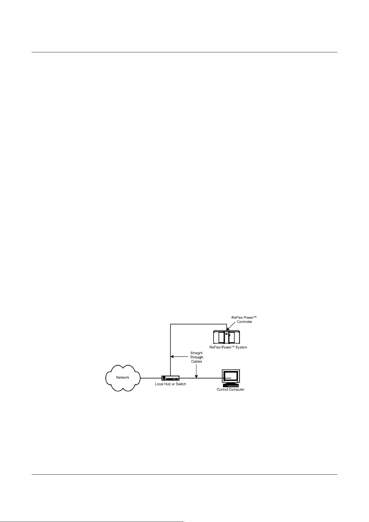
Ethernet Network Connection
A Network connection via local router, or switch isolates the local
nodes and segments from the rest of the Network, a hub does not. Use
two straight through cables to connect the control computer and the
ReFlex Power™ Controller from their respective Net/LAN connectors,
to a local router, switch or hub (Figure 2-1). ReFlex Power™ Controller
will DHCP if available from the network.
Figure 2-1. Ethernet Network Connection
M380056-03 Rev L 21
Page 26
ReFlex Power™ Programming Manual Controller Module Remote Programming
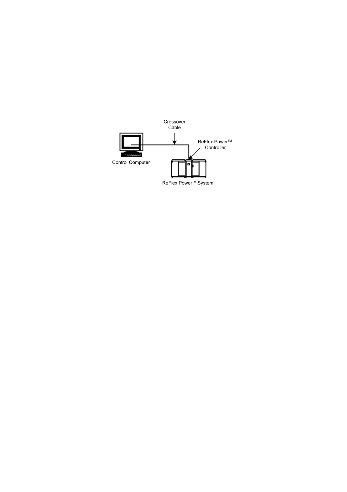
Direct Connection
If the control computer’s Ethernet interface does not support AutoMDIX, use a crossover cable to connect the control computer directly to
the Controller module between their respective Net/LAN connectors
(Figure 2-2). The factory default ReFlex Power™ Controller settings will
select an AutoIP address, it will be in the 169.254.1-254.NNN range, if
DHCP is not available, check the Control computer for proper settings.
Figure 2-2. Ethernet Direct Connection
5. Press the POWER switch on the Controller’s front panel to power on
the system. Allow time for the system to boot.
6. Launch the Ethernet connection (Section 2.4.3), or go straight to the
Net Test window to begin control communication (Section 2.6).
2.4.3 L
AUNCHING ETHERNET COMMUNICATION
Once the Ethernet connection is made and the system is powered on, the
Controller module’s LEDs, LAN and Con, are lit, and Net is lit during
network traffic.
When there is no Network traffic, the Net LED is not lit.
If the Con LED is not lit, the RFPC is not connected to a functioning
network.
If the LAN LED is not lit, the RFPC does not have an active TCP/IP
address, it has detected that it cannot retrieve an IP address via DHCP, or
if configured for a fixed IP address, the requested IP address is already in
use, or the RFPC can’t initialize the Ethernet system for some reason.
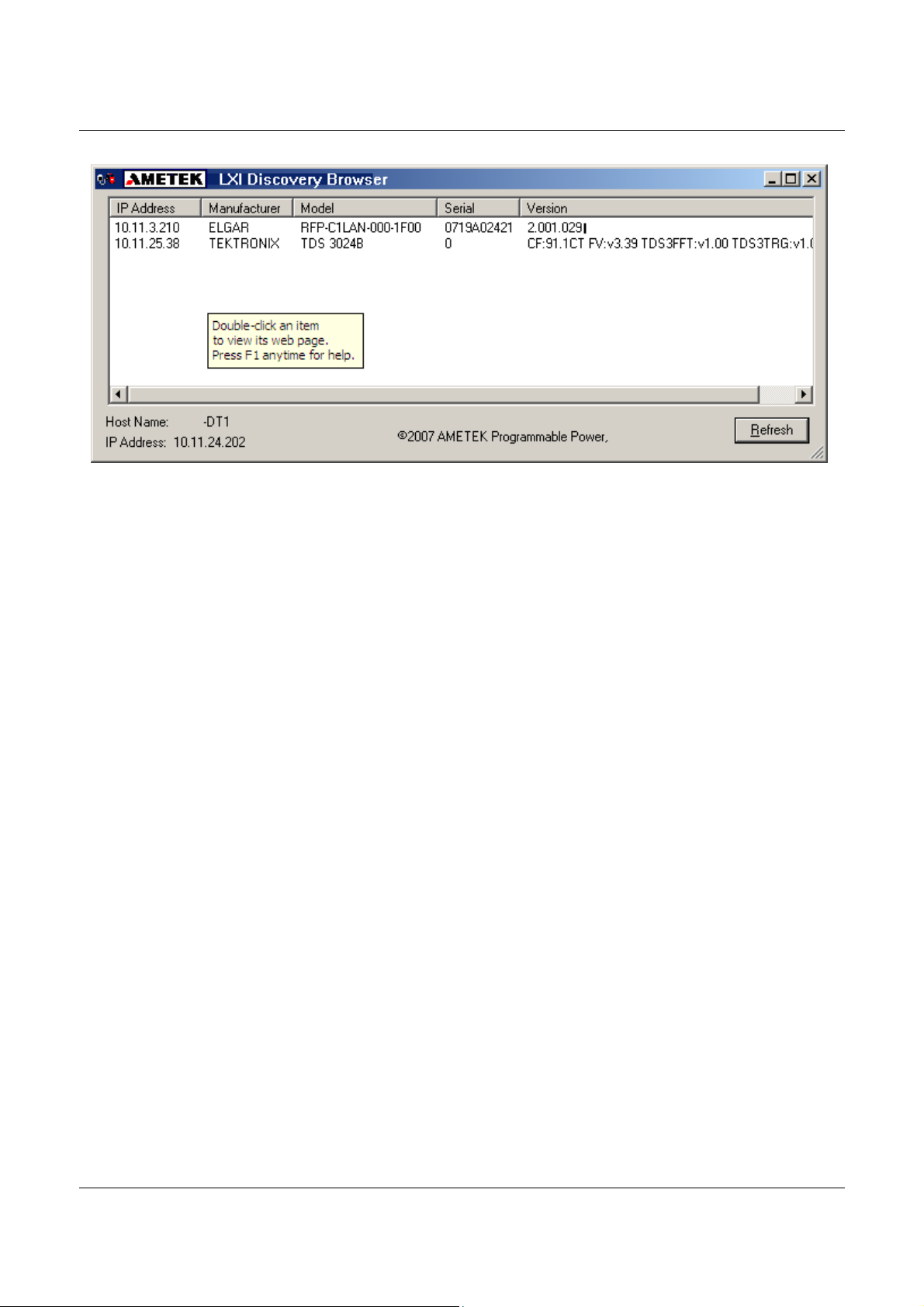
Execute the LXI™_Browser_setup file located in the ReFlex Power
executables folder on the ReFlex Power™ CD-ROM, M380399-01. This
will bring up the LXI™ Discovery Browser interface (Figure 2-3), which will
find and display the IP address of the ReFlex Power™ Controller module.
22 M380056-03 Rev M
Page 27
Controller Module Remote Programming ReFlex Power™ Programming Manual
Figure 2-3. LXI Discovery Browser Window
M380056-03 Rev L 23
Page 28
ReFlex Power™ Programming Manual Controller Module Remote Programming
2.5
REFLEX POWER™ ETHERNET INTERFACE
To bring up the ReFlex Power™ Ethernet Interface, in the LXI™
Discovery Browser, double click the IP address of the Controller module.
This brings up that Controller module’s HOME page (Figure 2-4).
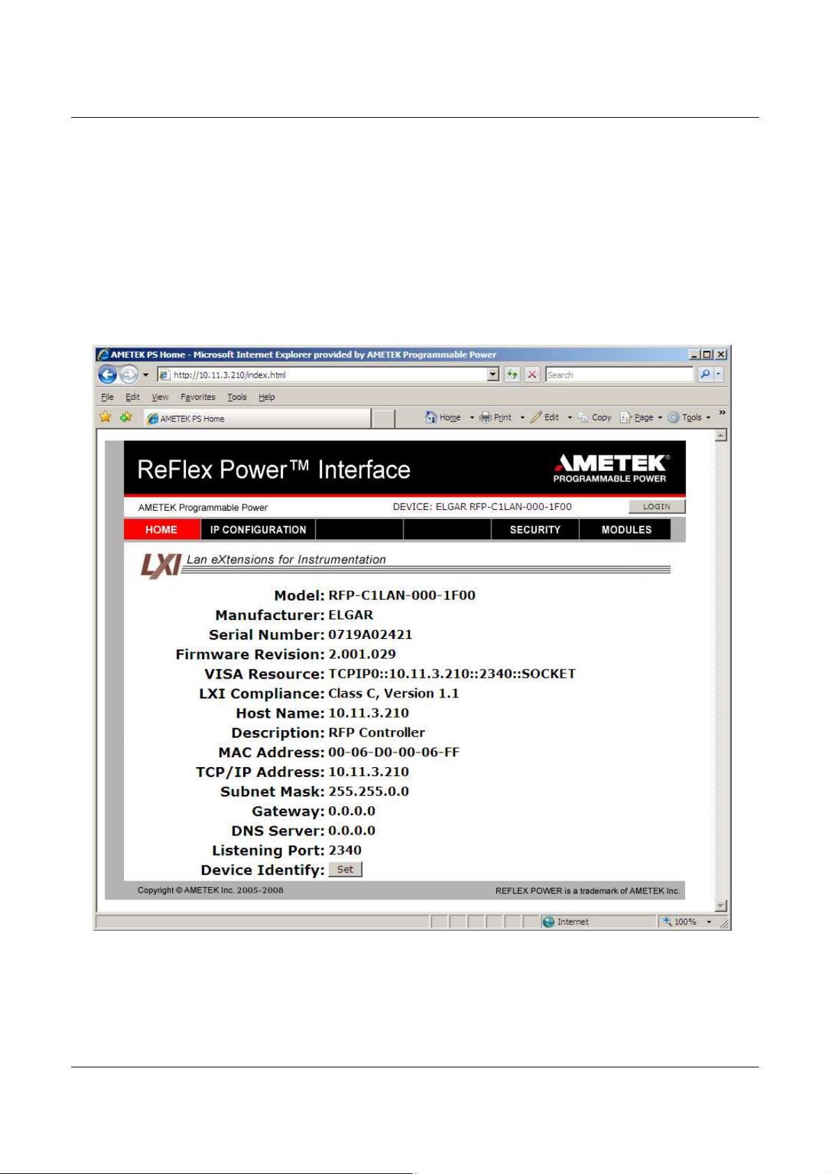
2.5.1 H
The ReFlex Power™ Ethernet interface HOME page displays the current
information about the specific Controller module that you are connected to.
OME PAGE
Figure 2-4. ReFlex Power™ Ethernet Interface Home Page
24 M380056-03 Rev M
Page 29
Controller Module Remote Programming ReFlex Power™ Programming Manual
If you are not sure you are connected to the correct Controller module, e.g.,
multiple Controller modules were listed in the LXI™ Discovery Browser, click
the SET button at the bottom of the HOME page (when clicked, the SET
button becomes the CLEAR button). SET causes that Controller module’s
LAN LED to blink for identification purposes. Click the CLEAR button to stop
the blinking (CLEAR button changes back to SET).
The HOME page has links (tabs) to three other pages in the ReFlex Power™
Interface: IP CONFIGURATION, SECURITY and MODULES. Also, in the
upper right area of the interface is the LOGIN button.
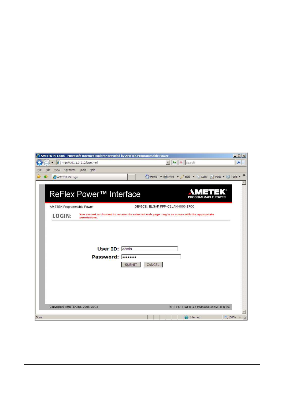
2.5.2 LOGIN
SCREEN
Click the LOGIN button to log in; clicking the IP CONFIGURATION tab also
brings up the LOGIN page, but with an error message prompting you to log in
(Figure 2-5).
Figure 2-5. LOGIN Page with Authorization warning
M380056-03 Rev L 25
Page 30
ReFlex Power™ Programming Manual Controller Module Remote Programming
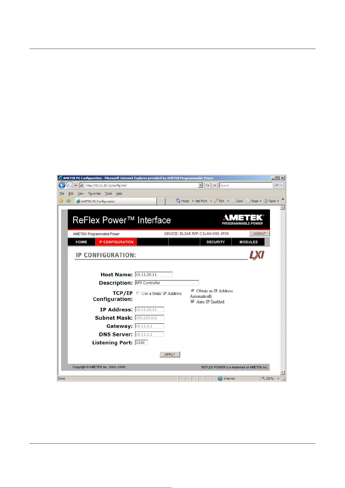
With authorized log-in (default parameters: User ID = admin; Password =
password), click the IP CONFIGURATION tab (Figure 2-6) where you can
customize the Host Name and Description, and/or select Use a Static IP
Address (Figure 2-7) to change IP Address, Subnet Mask, Gateway, DNS
Server and Listening Port. Please ask your IT Administrator for support.
2.5.3 IP
CONFIGURATION
The default IP Address configuration is DHCP-enabled and Auto IP-enabled. If
a DHCP server is not found, an address in the range of 169.254.[1 thru 254].[0
thru 255] will be selected. If there is no DHCP server on your local network,
your PC must also be configured for Auto-IP for the RFP system to be
discovered. For only DHCP, select “Obtain an IP Address Automatically” and
deselect “Auto IP Enabled”). Click the APPLY button to set your inputs.
Figure 2-6. IP CONFIGURATION Page, Default
26 M380056-03 Rev M
Page 31

Controller Module Remote Programming ReFlex Power™ Programming Manual
Figure 2-7. IP CONFIGURATION Static IP selected, but not yet applied.
When an IP Address is in error, it needs to be “checked”, an error message is
displayed, and the page refreshes back to the previous settings. (Figure 2-8)
An invalid IP address can be the result of invalid values entered in the address
fields, or the requested IP address is already in use. The chosen IP address
should be ‘PINGED’ to check that it is free and available for use before trying
to set the RFPC to that address.
M380056-03 Rev L 27
Page 32

ReFlex Power™ Programming Manual Controller Module Remote Programming
Figure 2-8. IP CONFIGURATION Page with Error Message for invalid IP Address
28 M380056-03 Rev M
Page 33

Controller Module Remote Programming ReFlex Power™ Programming Manual
2.5.4 S
ECURITY PAGE
Click the SECURITY tab to open the Security page, which displays the user
names and their permissions (Figure 2-9).
Figure 2-9. Security Page
Click the ADD button to add a new user and assign Password and Permissions
(Figure 2-10). To remove an existing user, select that user’s name and click the
REMOVE button. That row is deleted from the main Security page. To change
anything for an existing user, select that user’s name and click the EDIT button,
which takes you to the EDIT EXISTING USER page (Figure 2-11).
M380056-03 Rev L 29
Page 34

ReFlex Power™ Programming Manual Controller Module Remote Programming
Figure 2-10. Security: Add New User
In the ADD NEW USER page, click the cursor in each field and type the inputs,
select the Permission level from the drop-down menu and click the SUBMIT
button to set the new user settings. To clear the fields and start over, click the
RESET button. Clicking the CANCEL button reverts back to the previous
Security page without changes taking effect.
30 M380056-03 Rev M
Page 35

Controller Module Remote Programming ReFlex Power™ Programming Manual
Figure 2-11. Security: Edit Existing User
Make the desired changes to the applicable fields and click the SUBMIT button
to set the new user settings. To clear the fields and start over, click the RESET
button. Clicking the CANCEL button reverts back to the previous Security page
without changes taking effect.
M380056-03 Rev L 31
Page 36

ReFlex Power™ Programming Manual Controller Module Remote Programming
2.5.5 M
ODULES PAGE
Click the MODULES tab to reveal the “address” or Slot Location (SL), the
model number, the serial number and the firmware revision of the modules that
are installed in the system. (Figure 2-12 shows a system with the ReFlex
Power™ Controller module in Mainframe slot 1, and three AC power modules,
in slots 5, 8, and 12).
Figure 2-12. MODULES Page Showing Installed Power Modules
32 M380056-03 Rev M
Page 37

Controller Module Remote Programming ReFlex Power™ Programming Manual
2.6
LAUNCHING CONTROL COMMUNICATION
When the Ethernet interface is up and running, then start the communication
program as follows:
1. Copy the EnetTest.exe file supplied on the ReFlex Power™ CD-ROM into
any convenient directory on the control computer.
2. In its new location double-click the EnetTest.exe file.
This brings up the Elgar Net Test window (Figure 2-13) where the Host IP
and Port addresses must be set before control communication can begin.
Figure 2-13. Net Test Window
In the Host and Port fields of the Net Test window:
3. Enter the Host IP address acquired by the LXI™ Discovery Browser (Section
2.4.3), or the static IP address that you entered in the Ethernet Configuration
page (AutoIP will be in the range of 169.254.[1 thru 254].[0 thru 255].
4. Set the Port address to: 2340 (required)
5.
Click the Connect button.
M380056-03 Rev L 33
Page 38

ReFlex Power™ Programming Manual Controller Module Remote Programming
The field to the left of the Clear button, now appears white (not grayed out), to
allow SCPI command input.
It may be necessary to change the IP address, due to address conflicts and
other system requirements. (SYSTem:NETwork:IP <ipaddress>
).
Figure 2-14. Query IP Address Example
Figure 2-14 displays an example of querying and changing the IP address to
static. Note that the response to the IP address query after the address is
changed, includes the current IP address followed by the new IP address. The
following are commands associated with setting and querying the IP address:
SYSTem:NETwork:IP? Query to get the IP address from the
ReFlex Power™ system.
SYSTem:NETwork:IP <ipaddress> Sets the ReFlex Power™ system IP
address following the format:
NNN.NNN.NNN.NNN
The ReFlex Power™ System will reconfigure its TCP/IP address to the
requested address, after validating that the requested address is valid and
available for use. When the IP address is set, the IP address configuration is
automatically set to static.
The new IP address is reconfigured a few seconds after being validated, all
current TCP/IP connections will be closed, and new connections at the new
address will have to be created to communicate with the ReFlex Power™
System.
34 M380056-03 Rev M
Page 39

Controller Module Remote Programming ReFlex Power™ Programming Manual
Test the communication interface by issuing the *IDN? and/or *IDN<n>?
commands, which will return, respectively, the Controller’s or specific module’s
model and firmware versions without affecting output.
2.6.1 M
ODULE LOCATION IDENTIFICATION (ADDRESS
)
To control a specific module, use its address identified by its location in the
ReFlex Power™ Mainframe. Each Mainframe houses 12 address locations, one
for each single-width slot; the first slot on the left is numbered 1; the last on the
right is numbered 12. Additional mainframes continue the count; i.e., the
second Mainframe addresses are 13 through 24 from left to right (Figure 2-15).
The address for a double or triple-width module is always the rightmost slot
position that it occupies. Hence, a triple-width module covering slots 17, 18, and
19 is identified by address 19.
A ReFlex Power™ system is extendable up to eight (8) chassis, with the first
mainframe chassis (primary) configured as output only; any intervening chassis
would have both input and output inter-chassis connections, and the last would
be configured as input only. Refer to the ReFlex Power™ Operation Manual
(M380056-01) for additional information on multiple chassis interconnection
requirements.
Figure 2-15. Address Location and Chassis Configuration
Figure 2-16. Photo of Multi-Chassis ReFlex Power™ System
M380056-03 Rev L 35
Page 40

ReFlex Power™ Programming Manual Controller Module Remote Programming
2.7
2.6.2 C
Click within the Net Test window (Figure 2-14) to begin control
communications by inputting SCPI commands per the proper syntax and
conventions described herein.
SCPI COMMAND OPERATION
The SCPI command sets provide programming, query, and status commands
that facilitate remote control of the ReFlex Power™ system.
The system supports the SCPI 1999.0 status reporting data structures. These
structures are comprised of status registers and status register enable mask
pairs. The following sections describe these pairs.
2.7.1 E
The Error/Event Queue, defined by SCPI holds up to ten error events. Issue
the SYSTem:ERRor? query to read the queue in a First In/First Out (FIFO)
manner. The read operation removes the entry from the queue. Issue the
*CLS command to clear all entries from the queue.
The following SCPI-defined error codes are in the range of [-32768, 32767].
SCPI reserves the negative error codes and 0, while error codes greater than
0 are device-specific errors.
OMMUNICATION WITH THE SYSTEM
RROR/EVENT QUEUE
36 M380056-03 Rev M
Page 41

Controller Module Remote Programming ReFlex Power™ Programming Manual
Error Code
Description
No Error
Invalid
Index
When a command is issued to an empty slot
Wrong Module Type
Feature not supported
Feature Not Implemented
System too Busy
TrigChannel not available
Requested trigger channel is already used in the system
Wrong Group
Config/Oper
Module inhibited asserted
List Seq Buffer Full
Syntax error
Execution error
A command could not be executed due to the current condition of the module.
Data out of range
"Name not found/invalid
Name already exists
System Error
Queue overflow
Table 2-2. SCPI Error Codes
0
2
11
12
14
15
206
251
252
253
-102
-200
-222
The error queue is empty.
Command is not correct for the specific module type.
Specific command may not get implemented for the module type
Command will be implemented in the future
System is busy executing a previous command, the command causing this error will
not be executed.
Group creation failed for stated reason.
Module Inhibit is asserted in the RFPC for the ReFlex Power™ system.
The LIST being created, is too long.
An unrecognized command or data type was encountered.
Parameter exceeded range of valid values.
2.8
-292
-293
-331
-350
LXI™ AND SCPI CONFORMANCE INFORMATION
Requested File name either not found or the name was not valid.
Requested name already exists.
A valid command could not be executed due to some internal/earlier error.
The error queue can contain up to ten entries. If more than ten error/event conditions
are logged before a SYSTem:ERRor? Query, an overflow will occur; the last queue
entry will be overwritten with error -350. When the queue overflows, the least recent
error/events remain in the queue and the most recent error/events are discarded.
The ReFlex Power™ Controller Ethernet is IEEE 802.3 and LXI™ (LAN eXtensions
for Instrumentation) class C compliant.
The syntax of all SCPI commands implemented by the ReFlex Power™ system
and documented in this manual, are either SCPI commands confirmed in the SCPI
1999.0 Specification, Volume 2: Command Reference, or they are customized
commands, not part of the SCPI definition, but do conform to SCPI syntax.
M380056-03 Rev L 37
Page 42

ReFlex Power™ Programming Manual Controller Module Remote Programming
2.8.1 P
Table 2-3. Parameter Definitions
Type Valid Arguments
<bool> 1 or “ON”; 0 or “OFF”
<NRi>
<0+NRi> Zero and positive integer numeric values.
<-NRi> Negative integer numeric values.
<NRf>
<+NRf> Positive non-zero floating point numeric values.
<0+NRf> Zero and positive floating point numeric values.
<-NRf> Negative floating point numeric values.
<string> Text characters enclosed by double quotes.
<Arg> Text characters with no quotes.
<n> The address number of the module in the RFP chassis system.
The data format <NRi> is defined in IEEE-488.2 for integers.
Zero, positive and negative integer numeric values are valid data.
The data format <NRf> is defined in IEEE-488.2 for flexible Numeric Representation.
Zero, positive and negative floating point numeric values are some examples of valid data.
ARAMETER DEFINITIONS
Note: Channel number 0 is invalid for any auxiliary device, because the
ReFlex Power™ implementations of the SCPI language reserves channel 0
for the “global” address to address all channels.
2.8.2 N
UMERIC DATA DIMENSIONAL UNITS
The Ethernet interface accepts these dimensional units for numeric values of
parameters as listed below. For example, the command SOUR:VOLT 115
programs 115.0 volts when setting the output voltage of the supply.
Table 2-4. Numeric Data Units
Parameter Dimensional Unit
Voltage Volt
Current Ampere
Time Seconds
Frequency Hertz
Phase Angle Degrees
2.8.3 C
ONVENTIONS
Optional keywords and parameters are enclosed by left and right square
brackets: [ ]. The parameter <n>, in a command, indicates the address
number of the module being commanded.
• Discrete module numbers are separated by commas: <n,n,n>.
38 M380056-03 Rev M
Page 43

Controller Module Remote Programming ReFlex Power™ Programming Manual
• If nothing is entered, the default global command is automatically selected, if
the global context can be logically correct.
Required input parameters are enclosed by left and right less-than /
greater-than brackets: < > in the format indicated. For example:
• <bool> 0 or 1, for Off or On, respectively.
• <string> alphanumeric string enclosed by double quotes.
• <NRf> defined in IEEE 488.2 for flexible Numeric
Representation, e.g., zero, positive and negative floating
point numeric values.
• <NRi> defined in IEEE 488.2 for integers, e.g., zero, positive
and negative integer numeric values.
• <t> indicates Trigger channel input/output connections
(applies only to Controller and programmable DC
modules; see the Trigger command section of this
manual for further details on the <t> parameter).
The shorthand version of a command is indicated by capital letters
(minimum required components of a command). For example, SOURce
<n>:VOLTage <NRf>, can be written as:
• SOURCE<n>:VOLTAGE 120 //set output voltage to 120.0V
• SOUR<n>;VOLTAGE 120.0 //set output voltage to 120.0V
• SOUR<n>:VOLT 120 //set output voltage to 120.0V
2.8.4 Q
The query syntax is identical to the command syntax, but with a question mark
(?) replacing the command’s argument. For example, to query the
programmed output voltage on a Module at address 1, send the command,
SOUR1:VOLT?. A Module number is required. A value such as 65.00 will be
returned when read.
The ReFlex Power™ Controller requires all commands received to be
terminated with any combination of CR (0x0D), and or LF (0x0A). All
responses are terminated by default with CR/LF (0x0D 0x0A). Response
termination can be changed by using SYST:NET:TERM <NRi>. Each new
user connection is always initializes to CR/LF.
UERY SYNTAX
M380056-03 Rev L 39
Page 44

ReFlex Power™ Programming Manual Controller Module Remote Programming
Command
Description
Response
Definition for all Modules
2.9
COMMON SCPI COMMANDS
Table 2-5 shows commands that are common to all SCPI instruments.
Table 2-5. Common SCPI Commands
Clears all status reporting data structures including the Status Byte, the Standard
*CLS
*IDN<n>?
*OPC<n>?
*STB?
*SRE?
*SRE <NRi>
*ESR?
*ESE?
*ESE <NRi>
*RST<n>
*TST<n>
*TST<n>?
*TST?
Table 2-6. Module *TST? Error Response Bits Note: The *TST command can’t be interrupted.
Event Status Register, the Protection Event Status Register, and the Error Queue.
Enable registers are not cleared by this command.
Returns the device identification as an ASCII string.
Response: <Manufacturer>,<model>,<serial number>,<firmware version>
Example: ELGAR,RFP-C1LAN-000-0000,1234A56789,3.000.001
Operation Complete Query: Returns value of 1, when all pending operations are
complete. Returns value of 0, when long, or multipart commands are not complete.
Query User’s STatus Byte
Query the user’s enable bits in the Service Request Enable register
Set the enable bits in the Service Request Enable register
Query the user’s standard Event Status Register, if bit 0 is set, a *RST is required.
Query the user’s Enable Standard Event status register
Set the user’s enable bits in the Enable Standard Event status register.
Resets the specific slot module to its Power ON state. Clears status reporting data
structures, including the Protection Condition Status Registers. Enable registers are
not cleared by this command. *RST will reset all modules.
Initiate self test NOTE: Module must be OUTP:STATE 0 and not a group member.
Returns the results from the last self test the module performed. Returns a decimal
value, convert to Hex because more than one bit can be set. See Table 2-6.
Returns the results from all the modules in the system or’ed together. See *TST<n>?
0x00 No Selftest Errors
0x01 The Firmware Version of the Controller and Module are not compatible
0x02 Flash image, tag mismatch
0x04 Flash image, version mismatch
0x08 Isolation relay closed
0x10 Sense relay closed
0x20 Current measurement error. For DC, measured current not zero.
0x40 Voltage measurement error
0x80 Output turn on error
0x100 RAM Configuration error
0x200 Module Enable is false, selftest can’t be executed
0x400 Module On, Active selftest can’t be executed
0x800 OVP test failed
0x1000 UVP test failed
0x2000 Housekeeping supply fault
0x4000 Overtemp fault
0x8000 Ground fault
0x10000 Tried to run selftest on a Group Member
0x20000 OCP test failed
0x40000 Configuration or Calibration file error
0x1000000 Failed at 0% Volt setting, only with other bits set
40 M380056-03 Rev M
Page 45

Controller Module Remote Programming ReFlex Power™ Programming Manual
Response
Definition for all Modules
Command
Description
0x2000000 Failed at 10% Volt setting, only with other bits set
0x4000000 Failed at 90% Volt setting, only with other bits set
0x20000000
0x40000000 Selftest in progress. Only valid via *TST?, non applicable at module level.
0x80000000 Module Clear in progress. Only valid via *TST?, non applicable at module level.
The Controller is unable to detect with any other Modules (Chassis faults / Slot
Power?)
2.10
EIB SCPI COMMANDS
The EIB (Elgar Interface Bus) subsystem is a proprietary set of customized
commands, conforming to SCPI syntax but not defined by the SCPI
Standard.
2.10.1 EIB
EIB
:CONFigure
:DNUMber?
:INFormation
:ALL?
:VERBose?
:LADDress?
2.10.2 EIB
EIB
:CONFigure
:DNUMber?
:INFormation
:ALL?
:VERBose?
:LADDress?
SCPI C
SCPI C
OMMAND SUMMARY
OMMAND REFERENCE
EIB subsystem.
CONFigure sub-commands
Returns the number of devices in the system including the
controller.
Returns the model information string of the devices in the
system.
Returns the model information string of the devices in the
system with the corresponding logical Address.
Returns the logical Address of the devices in the system; the
first address is that of the controller.
M380056-03 Rev L 41
Page 46

ReFlex Power™ Programming Manual Controller Module Remote Programming
2.11
SYSTEM:NETWORK SCPI COMMANDS
2.11.1 SYSTEM:NETWORK
SYSTem
:ERRor?
:VERsion?
:FAULt?
:MODSRQ?
:NETwork
:AUTOIP <bool>
:AUTOIP?
:DESC <string>
:DESC?
:DHCPMODE <bool>
:DHCPMODE?
:DNS <IP Address>
:DNS?
:GATE <IP Address>
:GATE?
:HOST <string>
:HOST?
:IP <IP Address>
:IP?
:LANLED BLINKON
:LANLED BLINKOFF
:LANLED?
:MAC?
:MASK <IP Address>
:MASK?
:PING <IP address>?
:PORT <NRi>
:PORT?
:TERM <NRi>
:TERM?
SCPI C
OMMAND SUMMARY
42 M380056-03 Rev M
Page 47

Controller Module Remote Programming ReFlex Power™ Programming Manual
Command
Description
rack is being addressed). BLINKOFF stops LAN LED blinking.
2.11.2 SYSTEM:NETWORK
SYSTem
:ERRor?
:VERsion?
:FAULt? 3
:MODSRQ?
:NETwork
:AUTOIP <bool>1
:AUTOIP?
:DESC <string>
:DESC?
:DHCPMODE <bool>
:DHCPMODE?
:DNS <IP address>
:DNS?
:GATE <IP address>
:GATE?
:HOST <string>
:HOST?
:IP <IP address>
:IP?
:LANLED <BLINKON |
BLINKOFF>
:LANLED?
2,3
SCPI C
System subsystem.
Queries Error Queue for next error/event entry (first in, first
out). Entries contain an error number and descriptive text. A 0
return value indicates no error occurred; negative numbers
are reserved by SCPI. The maximum string length returned is
255 characters. The queue holds up to 10 error/entries. All
entries are cleared (per user) by the
Returns the SCPI version number for the instrument. The
response is in the format YYYY.V where the Y’s represent the
year and V represents the approved version number for that
year (e.g., 1999.0)
Returns a Hex number. If a module has an active Hardware
fault condition, the corresponding bit will be a ‘1’, else ‘0’.
Returns a Hex number. If a module has an active SRQ event,
the corresponding bit will be a ‘1’, else ‘0’.
Network Subsystem
Sets the network Auto IP mode.
0 = disable AutoIP; 1 = enable AutoIP
0 = AutoIP disabled; 1 = AutoIP enabled.
Set the network Description, a 64 character alphanumeric
string surrounded by quotes
Returns the network Description.
1 = enable, 0 = disable DHCP mode. Reboot to take effect.
Returns Y if DHCP Mode is enabled.
Returns N if DHCP mode is disabled.
Set the IP address of the Domain Name System for the device
(IP address is in the format NNN.NNN.NNN.NNN where
“NNN” = 0 through 255, inclusive.
Returns the network DNS address for the device.
Sets the network gateway IP address for the device. The IP
address format is NNN.NNN.NNN.NNN where “NNN” = 0
through 255, inclusive.
Returns the network gateway IP address for the device.
Set the network Host Name, a 15-character (maximum)
alphanumeric quoted “string”.
Returns the network Host Name
Configures the RFPC to STATIC IP mode, delays several
seconds, closes all network connections, then uses the new
IP address. The IP address format is NNN.NNN.NNN.NNN,
where “NNN” = 0 through 255, inclusive.
Returns two IP addresses: the first is the IP address presently
in use by the power supply; the second is the IP address to be
used when the system re-configures.
BLINKON blinks LAN LED. (Used to identify which RFPC in a
Returns state of the LAN LED:
0 – Off; 1 – On, 2 - blinking.
OMMAND REFERENCE
*CLS
command.
M380056-03 Rev L 43
Page 48

ReFlex Power™ Programming Manual Controller Module Remote Programming
Command
Description
:MAC?
:MASK <IP address>
:MASK?
:PING <IP address>?
:PORT <NRi>
:PORT?
:TERM <NRi>
:TERM?
1
When an AutoIP address is acquired, it’s range will be 169.254.1-254.NNN
2
To receive SRQ events at a host computer, a “TCPIP0::10.11.3.210::inst0::INSTR”
Returns the network MAC address.
xx-xx-xx-xx-xx-xx (Hexadecimal digit pairs)
Set the network Subnet Mask for the device. The mask is in
the format NNN.NNN.NNN.NNN
where “NNN” = 0 through 255, inclusive.
Returns the network Subnet Mask for the device.
Pings the IP address and returns the statistics
Set the network TCP/IP socket listening port. The Port
address is not changeable.
Returns the network TCP/IP socket listening port address,
which is 2340.
Set the return string terminator to be sent by the device. The
valid range is 1-4. The TERM value is user specific, for each
individual connection lifetime. Connection Default is 3.
Values indicate the following terminator(s):
1 = 0x0D only (CR), 2 = 0x0A only (LF), 3 = 0x0D 0x0A (CR
LF), 4 = 0x0A 0x0D (LF CR)
Returns the string terminator value used by the device.
connection must be instantiated by the IVI Driver, and the user application must call the
proper initialization and setup routines.
3
The Hex formatted number is 96 bits in length, which has a one-to-one correspondence for
each possible module in the system. The bits are numbered 96 down to 1.
2.13
RFP SERVICE REQUEST
2.13.1
BACKGROUND
The idea of Service ReQuest (SRQ) generation over Ethernet in RFP is to
allow the system to selectively and asynchronously alert each user to specific
events that have occurred in the system depending on which modules are
SRQ enabled. Because SRQ’s are asynchronous, the instrument does not
require to be polled, which lowers overhead and bandwidth requirements.
The RFP system provides a command and control interface via Ethernet.
Because the client side implementation of SRQ for Ethernet is implemented
using SUN RPC™ and VXI-11™ protocol, the RFPC implements a VXI-11
Server. A socket-based connection can set an SRQ event into the STatus
Byte register, (STB), but since there is no driver notification in this mode, it
would only be detected in a polling mode.
Note: One Ethernet connection, whether socket or instrument, will never ‘see’
another connection’s SRQ information or status. See below for details.
44 M380056-03 Rev M
Page 49

Controller Module Remote Programming ReFlex Power™ Programming Manual
2.13.2
The RFPC implements the RPC port 111-portmapper function for both TCP
and UDP. This allows the client to acquire the port # for the VXI-11 Server.
The VXI-11 Server connects to the client and translates the VXI-11 requests
into a form that can be sent to RFP modules, and receives the responses
from the RFP modules and formats them back into VXI-11 responses. The
VXI-11 server can support 16 concurrent client connections.
The VXI-11 server receives SRQ events from the RFPC (if enabled) and
sends (if SRQ enabled) a device interrupt request to the client.
The RFPC implements a multi-client SRQ mechanism based on the software
model of the SCPI Status Register structure. The RFPC maintains a SCPI
status and SRQ structure that is separate and unique per connection/user.
The association of a module level SRQ and the user occurs when the user
has programmed a module’s Protection EVent enable register (PEV) to a
non-zero value, and disconnected when the module’s PEV is set to zero, or
the user closes the Ethernet session.
There are two classes of SRQ’s, the first class is events generated from the
standard Event Status Register, (ESR) and the second class is events
generated from the module Protection Event register. (PE) The summary of
all these events is located in the STB.
THEORY OF OPERATION
2.13.3
The standard Event Status Register (ESR) handles events that are generally
caused by user commands. These include errors generated by command or
execution errors. There is a corresponding Enable Standard Event register
(ESE) that allows events to be enabled or masked off.
2.13.4
The Protection Event register (PE) handles all the events that are hardware
related. There is a corresponding Protection EVent enable register (PEV) that
allows these hardware events to be enabled or masked off.
2.13.5
The module level PE and PEV registers are allocated as one set, per module.
There is also one set of PE/PEV registers that serve as summary
accumulators. Also one set of STB, SRE, ESR, ESE registers, and an
ErrorQueue, that are allocated on a per user basis.
EVENT STATUS REGISTER
PROTECTION EVENT REGISTER
REGISTER ALLOCATION
M380056-03 Rev L 45
Page 50

ReFlex Power™ Programming Manual Controller Module Remote Programming
A unique set of these registers are allocated per each TCP/IP Socket
connection or VXI-11 channel connection, and released when the connection
is closed.
2.13.6
Group creation will clear both the PE and PEV registers at the module level.
If a PE, ESR, and STB event is active and the corresponding event in the
ESE, PEV and SRE is enabled, a SRQ will be generated. If several
simultaneous events occur, the first one will set the SRQ, to clear the SRQ,
all succeeding events will also need to be cleared.
To clear an SRQ, there are several commands that have been implemented
to make the job easier. The standard one of *STB?, is to see which class of
interrupt has occurred, an Event Status Register, Error Queue, and or a
Module Protection Event. The ESR is queried by the *ESR? command.
Which module caused a SRQ event can be determined by a
SYST:MODSRQ?. This command returns a 96 bit hex number (96 down to
1, Left to Right) on a user basis, that has a ‘1’ bit set corresponding to each
module number that the user has programmed non-zero PEV register value
that has caused the SRQ to be asserted.
To clear a PE, use the SYST:MODSRQ? to determine which module(s)
requires service, read their PE register. Then read the summaries PE
register, if there are no further SRQ’s pending, the SRQ bit in the STB
register should clear. If not, check for other events that are pending.
The linkage between a client and the RFP SRQ mechanism is made when a
module’s STATus<n>:PROTection:ENABle<Ni> bits are set non-zero. The
*SRE and client side driver must also enable SRQ for one to occur. The
summary set of PE/PEV registers can be used as a global SRQ
enable/disable for module based events on a per user basis.
EXECUTION TIME OPERATION
46 M380056-03 Rev M
Page 51

Controller Module Remote Programming ReFlex Power™ Programming Manual
3
3
3
3
3
3
2.13.7
SRQ
SYST
:MODSRQ?
1,2,3
:FAULt? 1
*
STB?
SRE?
SRE <Ni>
ESR?
ESE?
ESE <Ni>
STATus<n>:PROTection
:CONDition?
:EVENt?
:ENABle?
:ENABle<Ni>
STATus:PROTection
:EVENt?
:ENABle?
:ENABle<Ni>
RELATED
SCPI C
OMMANDS
System level command
Returns a Hex number. If a module has an active SRQ event, the corresponding
bit will be a ‘1’, else ‘0’
Returns a Hex number. If a module has an active Hardware fault condition, the
corresponding bit will be a ‘1’, else ‘0’.
Star level commands
Query User’s STatus Byte
Query the user’s enable bits in the Service Request Enable register
Set the enable bits in the Service Request Enable register
Query the user’s Standard Event status Register, if bit 0 set, a *RST is required.
Query the user’s Enable Standard Event status register
Set the user’s enable bits in the Enable Standard Event status register.
Module Status subsystem
Returns a real-time copy of the module protection event bits
Returns a summation of the module protection event bits, cleared on read.
Query the module protection event enable bits
Set the module protection event enable bits
Summary Status subsystem
A summation of the users module protection event bits, cleared on read.
Query the users protection event enable bits
Set the users protection event enable bits
1
The Hex formatted number is 96 bits in length, which is a one-to-one correspondence for every
possible module in the system. The bits are numbered 96 down to 1. As an example:
#H000000000000000000080006 shows Modules 24, 3 and 2 have posted an event.
2
To receive SRQ events at a host computer, a “TCPIP0::<TCP/IP Address>::inst0::INSTR” connection
must be instantiated by the IVI Driver, and the user application must send the proper commands to
the RFP system, and call the proper initialization and setup routines in the host computer and IVI
Driver.
3
The SRQ event bits are linked in exactly the same way as SRQ generation. One host connection
can’t ‘see’ another connection’s SRQ’s. The host linkage is created when a client sets a module’s
PEV register to a non-zero value. The linkage is broken when the PEV is set to zero.
M380056-03 Rev L 47
Page 52

ReFlex Power™ Programming Manual Controller Module Remote Programming
Error Queue not Empty
7 6 5 4 3 2 1 0
7 6 5 4 3 2 1 0
&&&
&&&
7 6 5 4 3 2 1 0
&&&&&
&&&&&
&
STAT<n>:PROT:EVENt ?
STAT<n>:PROT:ENAB <Ni>
STAT<n>:PROT:ENAB?
*STB?
*SRE <
NRi>
*SRE?
*ESE <Ni>
*ESE ?
*ESR?
SRQ
Error
Queue
6 Service ReQuested
5 Standard Event Status register
4,2 Error Event Queue / Message Available
7 Modules Power On Reset
5 Command Syntax error
4 Command execution error
3 Other errors
0 *RST required after a cold start
1,2,6 Reserved
<n> = Optional module #
<NRi> = Interger #
& = 'and' function
KEY:
5 4 3 2 1 0
Ver 0.10
Protection Event Register
Enable Standard Event register
standard Event Status Register
yte
SYST:MODSRQ?
a '1' bit set for each module
STAT<n>:PROT:COND?
of the PROT:EVENT Register
2 Summary bit
0 Constant Voltage Operation
4 Over Temperature Fault
1
2
2
0 will set this bit.
Note 2: Short duration mode changes of < 50 mSec. may
detected. For the Load Module: Bit 0 is for
SYST:FAUL?
7 Over Current Fault
6 Volt|Curr Mode Fault
5 Module Disabled
Protection Event Enable Register
ST
3 Output Voltage Fault
1 Constant Current Operation
atus
B
Note 1: Any changes in bits 7-3, 1-
Sticky bits, cleared on Query
not be
Resistance mode operation.
&
&
&
&
Returns a non-sticky version
7 ----
Service Request Enable / STatus Byte register bits
1 Protection Event Flag
0,3,6,7 Reserved
7 6 5 4 3 2 1 0
&
7 6 5 4 3 2 1 0
Returns a 96 bit hexnumber, with
requesting an SRQ (96..1)
Returns a 96 bit hex number, with
a '1' bit set for each module with
non-zero fault register (96..1)
='s 1, if any bit is set
&
48 M380056-03 Rev M
Page 53

Controller Module Remote Programming ReFlex Power™ Programming Manual
2.13.8
The following example shows the STB is initially zero. The SRE is enabled to
set SRQ if Message AVailable / Error Event Queue is asserted. A ‘bad
command’ is sent to the RFP system, which causes the Error Queue to have
an entry, which sets status bits in the STB. The setting of the bits in the STB
that match bits set in the SRE, will then cause bit 6 (SRQ) to be set, which
will generate the SRQ response if enabled by the host IVI-driver. To clear an
SRQ, the cause of the SRQ must be cleared. In the example below, reading
the Error Queue will cause the Message AVailable / Error Event Queue bits
to clear, if the Error Queue is empty, and if there are no other matching bits
between the STB and SRE or STB and PE registers, the STB SRQ bit will
clear, signaling the end of the SRQ event. The RFP system is now ready to
generate another SRQ event. If the SRQ bit does not clear, then there is
another pending SRQ event and the cause will need to be cleared before the
SRQ event will end. If there is a pending but not enabled SRQ event pending
and the corresponding bits in the ESE or PE registers are then set, this will
then generate an immediate SRQ and the client will need to issue commands
to clear these events before any other SRQ’s will be recognized.
SETTING THE
SRQ
BIT IN THE
STB,
AN EXAMPLE
M380056-03 Rev L 49
Page 54

ReFlex Power™ Programming Manual Controller Module Remote Programming
Comm
and Description
2.14
TRIGGER SCPI COMMANDS
The ReFlex Power™ Controller (RFPC) Trigger commands interact with the
Trigger commands of the High Power/Low Power programmable DC
modules, and not with any of the other modules. The role of the RFPC is to
source trigger signals to and/or from its front panel or rear panel backplane
buss. Please see the DC Module Remote Programming section of this
manual for details and requirements.
2.14.1
TRIGGER SCPI C
OMMAND SUMMARY
TRIGger
:DISPlay?
:INP <t>, OUTP <t>
:OUTP <t>, INP <t>
:TRIGger <t>
TRIGger<t>
:ENABle
:DISable
:SLOPe [POSitive | NEGative | BOTH | NONE]
:WIDTh <+NRf>
:LEVel [HIGH | LOW | ?]
2.14.2
TRIGger
:DISPlay?
:INP <t>, OUTP <t>
:OUTP <t>, INP <t>
:TRIG <t>
TRIGger<t>
:ENABle
:DISable
:SLOPe [POSitive | NEGative | BOTH |
TRIGGER SCPI C
:WIDTh<+NRf>
:LEVel [HIGH | LOW | ?]
OMMAND REFERENCE
Trigger subsystem.
Displays a list of the module numbers that use the
GPIO Buss signals.
Map RFPC’s GPIO Buss signals (t = a, b, c, or d) to
Front Panel triggers (t = fa, fb, fc, fd), specifying
direction. (one-one mapping)
Generate a RFPC trigger, t = fa-fd.
t = fa - fd; RFPC Buss/Front Panel trigger enable
t = fa - fd; RFPC Buss/Front Panel trigger disable
t = fa – fd sets the RFPC Front Panel trigger
input/output edge as positive, negative, or both.
NONE]
NONE disconnects the Buss to Front Panel
connection.
t = fa – fd sets the RFPC Front Panel trigger output
pulse width.
The WIDTh timing range is 2.0e-6 to 2.097 seconds.
t = fa - fb: sets RFPC Front Panel Trigger outputs fa
and/or fb to LEVEL mode, disabling trigger mode. The
level can only be queried after being set. Use
TRIG<t>:SLOPe NONE, to return to trigger mode.
50 M380056-03 Rev M
Page 55

Controller Module Remote Programming ReFlex Power™ Programming Manual
Command
Description
2.15
MEMORY SCPI COMMANDS
The RFP system has a section of writeable flash memory that is reserved for
module specific data; this includes Model, Serial #, calibration, and hardware
initialization information. In some instances, depending on module type, LIST
sequences are also stored in this area. The CRC:USRDAT? command
calculates and returns a CRC value for each file in the read / write file
system, it posts an error message if files have been added / removed or
changed without explicit command execution. If the supply is recalibrated
and the calibration is saved, this would not generate any errors as the file
update was explicitly requested.
The CLEar:USRDAT? command wipes the read / write file system of all files
and information that is not the minimum required for proper module operation,
it returns a CRC value for each of the required files, same as in the
CRC:USRDAT? Command.
If a hardware error occurs during the flash file system wipe process, an error
message will be posted.
2.15.1
MEMORY SCPI C
OMMAND SUMMARY
MMEMory<n>
:CLEar:USRDAT?
:CRC:USRDAT?
2.15.2
MMEMory<n>
:
CLEar:USRDAT?
:CRC:USRDAT?
MEMORY SCPI C
Memory subsystem.
Wipes all data from the flash file system, and then restores the
required information. The response string format is the same as for
the CRC:USRDAT? command. If the read response times out, issue
a SYST:ERR? to read the hardware flash related error encountered.
This command typically takes 20 - 25 seconds to execute.
Returns a CRC value for each file in the file system. The format is
“#HXXXXXXXX,Filename;” for each file. The last file entry will not
have a “;” appended and will have the termination specified by
SYST:NET:TERM <+NRI> command.
OMMAND REFERENCE
M380056-03 Rev L 51
Page 56

ReFlex Power™ Programming Manual Controller Module Remote Programming
This page intentionally left blank.
52 M380056-03 Rev M
Page 57

3.
3.1
3.2
DC MODULE REMOTE PROGRAMMING
INTRODUCTION
This section covers the remote programming of the ReFlex Power™
programmable DC power supplies, High Power DC (HPDC) and Low Power DC
(LPDC). This interface enables operation of the HPDC and LPDC power supplies
from a computer via the Ethernet, allowing full remote programming control and
monitoring of the power supply.
The syntax of all SCPI commands implemented by the ReFlex Power™ system
and documented in this manual, are either SCPI confirmed in the SCPI 1999.0
Specification, Volume 2: Command Reference, or they are customized
commands not part of the SCPI definition, but conform to SCPI syntax.
FEATURES AND FUNCTIONS
F
EATURES
• 16-bit programming and 16-bit readback of voltage and current
• Programmable over/undervoltage protection with reset
• Programmable overcurrent protection
• User selectable Constant-Voltage/Constant-Current mode, with reset
• Field-upgradeable firmware via Ethernet
• Soft calibration
P
ROGRAMMABLE FUNCTIONS
• Output voltage and current
• Soft limits for voltage and current
• Over/Undervoltage protection
• Programmable Overcurrent trip point
• Output enable/disable
• Maskable fault interrupt
• Full calibration
M380056-03 Rev M 53
Page 58

ReFlex Power™ Programming Manual DC Module Remote Programming
R
3.3
EADBACK FUNCTIONS
• Actual measured voltage and current
• Voltage and current settings
• Soft voltage and current limits
• Over/Undervoltage protection setting
• Status and Accumulated Status registers
• Programming error codes
• Fault codes
• Manufacturer, power supply model, serial number, and firmware
version identification
POWER-ON CONDITIONS
Table 3-1 presents remote power-on conditions for the programmable DC power
supplies.
Table 3-1. Remote Power-on Conditions
Condition Default
Voltage 0 Volts (initial power–on voltage). Also see CAL<n>:INIT:VOLT
Current 0 Amps (initial power–on current). Also see CAL<n>:INIT:CURR
Soft Voltage Limit Model maximum voltage
Soft Current Limit Model maximum current
OCP Trip Voltage
OVP Trip Voltage
Output Relay State Auto Close of ISOL/SENSE on :STATE 1 command
Output OFF
Group No Modules Grouped, (such as parallel)
Model maximum current +20% (initial power–on OCP).
See CAL<n>:INIT:CURR:PROT
Model maximum voltage +7% (initial power–on OVP).
See CAL<n>:INIT:VOLT:PROT
3.4
ERROR CODES
The ReFlex Power™ system supports the SCPI 1999.0 status reporting data
structures. These structures are comprised of status registers and status register
enable mask pairs. The following sections describe these pairs.
3.4.1 E
The programmable DC power supplies maintain an Error/Event Queue as
defined by SCPI. The queue holds up to ten error events. Read it by
issuing the SYSTem:ERRor? query, which reads in a First In/First Out
(FIFO) manner. The read operation removes the entry from the queue.
54 M380056-03 Rev M
RROR/EVENT QUEUE
Page 59

DC Module Remote Programming ReFlex Power™ Programming Manual
REPLY
DESCRIPTION
The *CLS command will clear all entries from the queue.
The following error codes are defined in the SCPI 1999.0 specification and
are supported by the DCPS. Error codes are in the range of [-32768, 32767].
SCPI reserves the negative error codes and 0, while error codes greater than
0 are device specific errors.
0, No error
The error queue is empty.
-102, Syntax error
An unrecognized command or data type was encountered.
-200, Execution error
This is a generic error when a specific error could not be identified. An
execution error could be the result of the following condition:
A command could not be executed due to the current operational
condition.
-222, Range Error
A <program data> element is out-of-range; for example, programming
150V, when the maximum allowed value is 135V.
-350, Queue overflow
The Error/Event Queue can contain up to 10 entries. If more than 10
error/event conditions are logged before the SYSTem:ERRor? query, an
overflow will occur; the last queue entry will be overwritten with error -350.
When the queue overflows, the least recent error/event remains in the queue
and the most recent error/event is discarded.
NOTE: Some SCPI commands will generate the following replies, which can
be viewed with the SYST:ERR? command:
Invalid 5PCalData
Unable to open Module Data file - file system
problem
Invalid Password.
Unable to open Module Data file - file is
locked
Unable to change Output State - Output
Inhibited
Error occurs at the boot up sequence if the 5-point
calibration data are not valid.
Error occurs at the boot up sequence if the
module data file does not open
CAL<n>:UNLOCK
files to store the calibration or module data, but
the password used is incorrect]
The
CAL<n>:UNLOCK
before using
“Password” [to unlock the
command is not used
CAL<n>:STORE
OUTP<n>:STATE <bool>
the DC module
command
[to power on or off
M380056-03 Rev L 55
Page 60

ReFlex Power™ Programming Manual DC Module Remote Programming
REPLY
DESCRIPTION
Command
Description
Unable to change Output State
Relay hot-switching prohibited or Parallel
Slave
Unable to close Default Sense Relay, Default
Isol Relay is open
Unable to open Output Relay, Sense Relay is
closed
Relay hot-switching prohibited
Unable to change Polarity, an Output or
Sense relay is closed
Unable to close Sense relay, Output Relay is
NOT closed
Module Firmware too old to support this RFP
Controller Firmware Revision
OUTP<n>:STATE <bool>
the DC module
OUTP<n>:STATE <bool>
the DC module
User tries to close the sense relay with the
[to power on or off
[to power on or off
CAL<n>:INIT:DEFAULT:SENSE <bool>
command when the isolation relay is open
User tries to open the isolation relay with the
CAL<n>:INIT:DEFAULT:ISOL <bool>
command when sense relay is closed
User tries to open the isolation relay with the
OUTP<n>:ISOL <bool>
output voltage is on
User tries to change the polarity of the module
with the
when Isolation and sense relay is closed
User tries to close the sense relay with the
OUTP<n>:POL <bool>
OUTP<n>:SENSE <bool>
isolation / output relay is not closed
The addressed module’s firmware version is too
old to be compatible with the RFPC’s firmware
command when the
command when the
command
3.5
COMMON SCPI COMMANDS
The following commands are common to all SCPI instruments and declared
mandatory by IEEE-488.2. In the following table, the DCPS is defined as the
“device” on the bus.
Table 3-2. Common SCPI Commands
*CLS<n>
*IDN<n>?
*OPC<n>?
*RST<n>
*TST<n>
*TST<n>?
Clears module hardware faults latch
Returns the device identification as an ASCII string.
Response: <Manufacturer>,<model>,<serial number>,<firmware version>
Example: ELGAR,RFP-D1016-021,1234A56789,3.000.001
Operation Complete Query: Returns the integer value “1” when all pending
operations are complete.
Resets the supply to its Power ON (PON) state.
Clears status reporting data structures the Protection Event and the Condition
Status Registers. Enable registers are not cleared by this command. RST will reset
all modules.
Initiate self-test
Returns the results from the last self test the module performed. Returns a decimal
value, convert to Hex because more than one bit can be set. See Table 2-6
56 M380056-03 Rev M
Page 61

DC Module Remote Programming ReFlex Power™ Programming Manual
3.6
CALIBRATION SCPI COMMANDS
CAUTION
Before attempting to execute any of the HP/LP DC power supplies calibration commands,
follow the calibration procedures in the ReFlex Power™ Operation Manual (M380056-01),
DC Power Supplies Section. Qualified personnel who are appropriately trained to deal with
attendant hazards must perform calibration. If calibration is not performed properly,
functional problems could arise, requiring that the supply be returned to the factory.
3.6.1 CALIBRATION
CALibrate[n]
:INITial
:CURRent <0+NRf>
[:AMPLitude] <NRf>
[:AMPLitude]?
:PROTection <NRf>
:PROTection?
:VOLTage <0+NRf>
[:AMPLitude] <NRf>
[:AMPLitude]?
:PROTection <NRf>
:PROTection?
:STATe <Bool>
:STATe?
:UNDERVOLTage
:PROTection <NRf>
:PROTection?
:DEFAult
:OUTPut
:CURRent
:COUNTS <NRi>
:FIVEPOINT<1-5> <NRi>
:FIVEPOINT?
:PROTection
:COUNTS <NRi>
:VOLTage
:COUNTS <NRi>
:FIVEPOINT<1-5> <NRi>
:FIVEPOINT?
:PROTection
:COUNTS <NRi>
:MODule
:VOLTage?
:CURRent?
SCPI C
OMMAND SUMMARY
M380056-03 Rev L 57
Page 62

ReFlex Power™ Programming Manual DC Module Remote Programming
Command
Description
1
protection.
Set Current DAC
setpoint, in counts
:LOCK
:STORe
:UNLock <string>
:REVERT:FACTory
3.6.2 CALIBRATION
CALibrate<n>
:INITial
:CURRent
[:AMPLitude] <NRf>
[:AMPLitude]?
:PROTection <NRf>
:PROTection?
:VOLTage
[:AMPLitude] <NRf>
[:AMPLitude]?
:PROTection <NRf>
:PROTection?
:UNDERVOLTage
:PROTection <NRf>
:PROTection?
:STATe <bool>
:STATe?
SCPI C
Calibration subsystem. Module ‘n’.
Sets the power-on default value of current.
Query the power-on default value of current
Sets the power-on default value of the over current
protection.
Query the power-on default value of the over current
protection.
Sets the power-on default voltage. Should be set to zero
volts to avoid hot switching of output relay.
Query the power-on default voltage. Should be set to zero
volts to avoid hot switching of output relay.
Sets the power-on default value of the over voltage
protection.
Query the power-on default value of the over voltage
protection.
Set the initial POR output state of the unit
Query the initial POR output state setting of the unit
Sets the power-on default value of the under voltage
protection.
Query the power-on default value of the under voltage
OMMAND REFERENCE
Sets initial settings to Factory defaults of 0.0
:DEFAult
:OUTPut
:CURRent
:COUNTS <NRi>
:FIVEPOINT<1-5> <0+NRf>
:FIVEPOINT?
:PROTection
:COUNTS <NRi>
:VOLTage
:COUNTS <NRi>
:FIVEPOINT<1-5> <NRf>
Volts/Amps/UVP, OVP/OCP to Module Max values and
POR State to Off.
Sets the current output calibration point (1 through 5). The
actual output current is measured with an external meter.
Returns 5 pairs of current calibration setpoint count and
related current values
Set Protection value 0-4095
Set Voltage DAC setpoint, in counts
Sets the voltage output calibration point (1 through 5). The
actual output voltage is measured with an external meter.
58 M380056-03 Rev M
Page 63

DC Module Remote Programming ReFlex Power™ Programming Manual
Command
Description
Returns Module Current rating
Command
Description
3.7
:FIVEPOINT?
:PROTection
:COUNTS <NRi>
:MODule
:VOLTage?
:CURRent?
:LOCK
:UNLock <string>
:STORe
:REVERT:FACTory
Note 1: If CAL:INIT:STATe is ‘1’, the module will automatically turn on as if an OUTP:STATe 1
command had been received. This will only occur during initial power up, *RST will only restore
the saved CAL:INIT values. The unit will not automatically turn on, if enabled, after a *RST.
MEASURE SCPI COMMANDS
3.7.1 MEASURE
SCPI C
Returns 5 pairs of voltage calibration setpoint count and
related voltage values.
Set Protection value 0-4095
Returns Module Voltage rating
Disables access to the non-volatile memory. Prevents
attempts to store calibration values.
Unlocks the non-volatile memory to store calibration
constants. The access string is “6867”.
Stores the calibration constants in non-volatile memory.
Restores the original factory calibration, into non-volatile
memory. Wait 30 seconds and then Power cycle.
OMMAND SUMMARY
MEASure[n]
:CURRent?
:POLARity?
:VOLTage?
:POWer?
3.7.2 MEASURE
MEASure<n>
:CURRent?
:POLARity?
:VOLTage?
:POWer?
SCPI C
Measure subsystem. Module ‘n’.
Returns the floating point value of the DC output current in amps.
The value will be negative if the polarity relay is in the INV state.
Returns Polarity Relay setting.
Returns the floating point value of the DC output voltage in volts.
The value will be negative if the polarity relay is in the INV state.
Returns the power in Watts that are delivered to the Load.
OMMAND REFERENCE
M380056-03 Rev L 59
Page 64

ReFlex Power™ Programming Manual DC Module Remote Programming
Command
Description
3.8
OUTPUT SCPI COMMANDS
3.8.1 OUTPUT
SCPI C
OMMAND SUMMARY
OUTPut[n]
:ISOLation <bool>
:DEFault <bool>
:DEFault?
:ISOLation?
:POLarity <NORM/0/OFF|INV/1/ON>
:POLarity?
:PROTection
:DELAY <NRf>
:DELAY?
:FOLD <NRi>
:FOLD?
:SENSe <bool>
:DEFault <bool>
:DEFault?
:SENse?
:STATe <bool>
:STATe?
:TRIPped?
:MODFault <bool>
:MODFault?
:CLEar <bool>
:CLEar?
:DPDelay
:TIMER <NRf>
:TIMER?
3.8.2 OUTPUT
OUTPut<n>
:ISOLation <bool>
:ISOLation?
:
:
:POLarity
<NORM/0/OFF | INV/1/ON>
DEFault <bool>
DEFault?
SCPI C
OMMAND REFERENCE
Output subsystem. Module ‘n’.
Turns 1/ON or 0/OFF, the output isolation relay. The output
voltage must be set to zero prior to issuing this command. The
ISOL relay can’t be opened if Sense relay is closed.
Query the state of the ISOLation relay. 0 = open, 1 = closed.
Sets DEFault state of ISOL Relay, POR default state is ON. The
ISOL/SENSe relays will be automatically sequenced during the
STATE command.
Query DEFault state of Isolation relay
Changes the state of the polarity relay. This command requires
that the isolation/sense relays be opened beforehand. If the
isolation relay is closed when this command is attempted, the
state of the polarity relay will not change, and an error message
60 M380056-03 Rev M
Page 65

DC Module Remote Programming ReFlex Power™ Programming Manual
operation.
Used
to enable / disable
Fault Group operation.
allow a Fault Group to be cleared.
.
will be generated. The default Polarity will be Normal with the
Positive Output on Out 1.
:POLarity?
:PROTection
:STATe <bool>
:STATe?
:SENSe <bool>
:SENSe?
:DEFault <bool>
:DEFault?
:TRIPped?
:MODFault <bool>
:DELAY <NRf>
:DELAY?
:FOLD <NRi>
:FOLD?
Query the state of the polarity relay.
Set Shutdown delay timer value, 0 to 40.95 Seconds
Query Shutdown delay timer value
Shutdown Mode, 0= Normal CC/CV mode operation.
1= Fault if Supply switches into Voltage mode.
2= Fault if Supply switches into Constant Current mode.
Query Shutdown Mode setting.
Closes the isolation/sense relays. Sets the output voltage and
current to programmed values, turns on the supply. Valid
arguments are 1/ON or 0/OFF. *RST state value is OFF.
CAUTION: Ensure that suitable delays are incorporated to
preclude hot switching of the isolation relay. See :DEFault
keyword entry for automatic relay operation..
Query the state of the unit. 1 means unit is on and 0 means unit
is off
Turns On/Off the output Sense relay. The output ISOL relay
must be closed to close the Sense relay. Valid arguments are
1/ON or 0/OFF.
Query the state of output SENSe relay.
Sets DEFault state of SENSe Relay, POR default state is ON.
The ISOL/SENSe relays will be automatically sequenced during
the STATE command.
Query DEFault state of SENSe Relay.
Returns the integer value 1 (TRIPPED) or 0 (UNTRIPPED) state
of the output.
When 1/ON, sets Module Trigger Out to assert HIGH when a
HW fault is detected. 0/OFF returns Trigger out to normal
:MODFault?
:CLEar <bool>
:CLEar?
:
DPDelay
:TIMER
:TIMER?
<NRf>
Query the state of Module Fault Mode
When in Module Fault mode, 1/ON, forces Trigger out to LOW to
Query if the state of the Module Fault output is forced LOW.
Down Programmer turn off delay timer (maximum ON time)
Programs the down programmer to be ON for a maximum of 0.1
to 60.0 seconds. Programming 0 seconds (Default setting)
disables the timer, and the down programmer is always enabled
If the timer counts down and expires, the down programmer will
be turned OFF. The timer starts when the down programmer
needs to sink current to keep the supply output in regulation.
The programmed value is automatically saved. It is not cleared
by *RST. SYST:ERR?:- ELGAR_NOT_ SUPPORTED is
returned if the feature is not implemented.
Returns the setting for the delay timer. If 0.0 is returned, the max
on delay timer is disabled, and then down programmer enabled.
This is the default operating mode. If the feature is not
implemented ELGAR_NOT_SUPPORTED is returned.
M380056-03 Rev L 61
Page 66

ReFlex Power™ Programming Manual DC Module Remote Programming
3.9
SOURCE SCPI COMMANDS
3.9.1 SOURCE
SOURce[n]
:CURRent <NRf>
:CURRent?
:LIMit <NRf>
:LIMit?
:PROTection <NRf>
:PROTection?
:TRACKing <bool>
:TRACKing?
:MODE?
:RAMP See Table 3-9. For Software Ramps
:TRIGger See Table 3-8. For Software Setpoints
:VOLTage <NRf>
:VOLTage?
:LIMit <NRf>
:LIMit?
:PROTection <NRf>
:PROTection?
:TRACKing <bool>
:TRACKing?
:RAMP See Table 3-9. For Software Ramps
:TRIGger See Table 3-8. For Software Setpoints
:UNDERVOLTage
:PROTection <NRf>
:PROTection?
:TRACKing <bool>
:TRACKing?
:TRIPped?
SCPI C
:ENABle <bool>
:ENABle?
OMMAND SUMMARY
62 M380056-03 Rev M
Page 67

DC Module Remote Programming ReFlex Power™ Programming Manual
Command
Description
Sets the overvoltage protection trip point in volts.
3.9.2 SOURCE
SOURce<n>
:CURRent <NRf>
:CURRent?
:LIMit <NRf>
:LIMit?
:PROTection <NRf>
:PROTection?
:TRACKing <bool>
:TRACKing?
:VOLTage <NRf>
:VOLTage?
:LIMit <NRf>
:LIMit?
:PROTection <NRf>
:PROTection?
:TRACKing <bool>
:TRACKing?
:ENABle <bool>
:ENABle?
:UNDERVOLTage
:PROTection <NRf>
:PROTection?
:TRACKing <bool>
:TRACKing?
:TRIPped?
:MODE?
Query, 1 is constant current mode, 0 is voltage mode. See
:RAMP
:TRIGger
:RAMP
:TRIGger
SCPI C
OMMAND REFERENCE
Source subsystem. Module ‘n’.
Sets the output current in amps.
Query the set output current in amps.
Sets an upper soft limit on the programmed output current for
the supply.
Query an upper soft limit on the programmed output current
for the supply.
Sets the overcurrent protection trip point in amps
Query the overcurrent protection trip point in amps
Set the over current protection to tracking. 1 means turn on
the tracking supervisory and 0 means turn off the tracking
supervisory
Query the tracking supervisory status.
OUTP[n]:PROT:FOLD command.
See Table 3-9. For Software Ramps
See Table 3-8. For Software Setpoints
Sets the output voltage of the supply in volts. *See note at end
of this table.
Query the set point of the output voltage of the supply in volts.
Sets the upper soft limit on the programmed output voltage.
Query an upper soft limit on the programmed output voltage.
Query the set point of the overvoltage protection trip point in
volts.
Set the over voltage protection mode to tracking. 1 equals on,
and 0 turns off the tracking supervisory.
Query the tracking supervisory status.
Disable OVP when OFF, Save current setting, and set OVP to
factory maximum value. When ON, restore the saved OVP
setting.
Query if OVP is Enabled or Disabled.
See Table 3-9. For Software Ramps
See Table 3-8. For Software Setpoints
Sets the undervoltage protection trip point in volts.
Query the set point of the undervoltage protection trip point in
volts.
Set under voltage protection tracking. 1 = On, 0= Off.
Query the tracking supervisory status.
Returns 1 if the supply has an undervoltage fault
*Note: Set and Query the state of the polarity relay using the OUTPut<n>:POLarity
command.
M380056-03 Rev L 63
Page 68

ReFlex Power™ Programming Manual DC Module Remote Programming
Command
Description
3.10
INPUT SCPI COMMANDS
3.10.1 INPUT
INPut<n>
3.10.2
INPut<n>
:MENAble:MODE <NRi>
:MENAble:MODE?
:MENAble:STATE?
SCPI C
OMMAND SUMMARY
:MENAble:MODE <NRi>
:MENAble:MODE?
:STATE?
INPUT SCPI C
0 = Allows the Module ENAble signal to turn the DC supply back On,
only if it was faulted off by Module ENAble going false. (Default
setting) If the supply was off by Module ENAble, and a *RST<n> is
issued, the DC supply will not turn on, unless a OUTP<n>:STAT 1
command is issued.
1 = Prevents the Module ENAble signal from turning the DC supply
On. An OUTP:STAT 1 is required to turn the supply back on.
2 = Module ENAble will always try to turn on the DC supply when it
goes from Off to On. Note: Settings are automatically saved.
Query the Module ENAble MODE setting. Default is 0.
1 = The Hardware Module ENAble signal is asserted, the module can
be turned On.
0 = When the Hardware Module ENAble is false; the module is Off.
OMMAND REFERENCE
Note: The usage of the OUTPut<n>:MODFault On command will temporarily disable
the operation of the INPut<n>:MENA:MODE command while it’s active.
64 M380056-03 Rev M
Page 69

DC Module Remote Programming ReFlex Power™ Programming Manual
Command
Description
mode switches back to CV.
Default timer value is 0.
Mnemonic
3.11
STATUS SCPI COMMANDS
3.11.1
STATUS SCPI C
OMMAND SUMMARY
STATus[n]
:MODE
:DELAY <0+NR1>
:DELAY?
:MODule
:ENABles <0+NR1>
:ENAB?
:FAULts?
3.11.2
STATus<n>
:MODE:DELAY <0+NR1>
:MODE:DELAY?
:MODule
:ENABles<0+NR1>
:ENABles?
:FAULts?
STATUS SCPI C
Status subsystem. Module ‘n’.
Sets the delay timer for responding to a status change from CV
to CC mode. Value in counts: 0 to 255, of approximately 20ms
for each count. Delay counter is immediately reloaded when the
Returns the CV to CC status delay timer value. *RST sets to 0.
Enable supervisory. See Table 3-3 for enable values.
Query the enabled supervisories
Query the module faults
OMMAND REFERENCE
Table 3-3. DC Fault and Enable Register
Bit Hex Value
0 0x00000001 LDF Line Drop Fault
1 0x00000002 RSF Reverse Sense Fault
2 0x00000004 OCP Over Current Fault
3 0x00000008 OVP Over Voltage Protection Fault
4 0x00000010 ROCP Redundant Over Current Protection Fault
5 0x00000020 ROVP Redundant Over Voltage Protection Fault
6 0x00000040 UVP Under Voltage Protection Fault
7 0x00000080 RESERVED
8 0x00000100 IMPTEMPHSK1 Heatsink1 Temperature is Warm
9 0x00000200 IMPTEMPHSK2 Heatsink2 Temperature is Warm
10 0x00000400 OVTEMPHSK1 Heatsink1 Temperature Exceeds Limit
11 0x00000800 OVTEMPHSK2 Heatsink2 Temperature Exceeds Limit
12 0x00001000 AFF Air Flow Fault
13 0x00002000 UVP5V Internal 5V Under Voltage Fault
14 0x00004000 OVP5V 5V Over Voltage Fault
Description
M380056-03 Rev L 65
Page 70

ReFlex Power™ Programming Manual DC Module Remote Programming
Mnemonic
Bit Hex Value
15 0x00008000 UVPP12V +12V Under Voltage Fault
16 0x00010000 OVPP12V +12V Over Voltage Fault
17 0x00020000 UVPM12V -12V Under Voltage Fault
18 0x00040000 OVPM12V -12V Over Voltage Fault
19 0x00080000 GNDF Ground Fault
20 0x00100000 OCLF Outer Control Loop Fault
21 0x00200000 ICLF Inner Control Loop Fault
22 0x00400000 RESERVED
23 0x00800000 RESERVED
24 0x01000000 PRIENA Primary DC Bus Enable Fault
25 0x02000000 PRST Power-on Reset Fault
26 0x04000000 GRPF Group Fault
27 0x08000000 MDENA Module Enable False (Does not activate Fault Led)
28 0x10000000 CNVF Converter Fault
29 0x20000000 PAOC Primary Average Overcurrent Fault (PAOC or AVG_TRP)
30 0x40000000 Analog Fault Analog Fault
31 0x80000000 RESERVED
Note: Turning off Supervisory Enables can allow permanent and catastrophic damage to the
Module to occur.
Description
3.12
TRIGGER SCPI COMMANDS AND LISTS
The ReFlex Power system provides for two programming modes, these
modes are only available in the High Power and Low Power DC (HPDC and
LPDC) modules: the List/Trigger mode, and the Software Setpoint and
Ramps mode.
The List/Trigger mode (Section 3.12.1) provides the ability to program
accurate and tightly timed, externally-synchronized events ranging from
simple, synchronized output changes to complex multiple-step, multi-module,
externally and internally driven sequences (Lists), which can be driven by
hardware trigger signals.
The Software Setpoint and Ramps mode (Section ) provides the ability to
program a software-triggered voltage and/or current setpoint change, and to
ramp the supply output, with an execution latency of 10-20 mSec.
3.12.1
LIST
AND TRIGGER COMMAND OPERATION
This section describes first the Trigger architecture and behavior, then
describes Lists and List/Trigger requirements. Each programmable High
Power and Low Power DC power module has a module level trigger input
and output signal as a part of its front panel control interface. The ReFlex
Power™ Controller has four general-purpose I/O signals, which are bussed to
66 M380056-03 Rev M
Page 71

DC Module Remote Programming ReFlex Power™ Programming Manual
all modules via high-speed backplane signals. Each can be programmed to
control the module or have the module indicate its condition. This capability is
extendable to grouped modules as well.
In addition to or in conjunction with these synchronizing features, the ReFlex
Power™ module(s) can process a sequence (List) of pre-programmed
commands, frequently driven by trigger signals, to control its output.
Figure 3-1 diagrams the various trigger ports and trigger architecture in the
ReFlex Power™ system. Each module has a unique set of trigger in/out
ports. These are termed the module ports and have the same address as the
power module. There are up to four bussed trigger ports that are shared by
all modules. Each power module and the ReFlex Power™ Controller can
access these signals to either send or to receive trigger signals. The limitation
on the number of these signals is due to their also being used to support DC
series groups and to create fault groups. Hence the sum of DC series groups,
fault groups and allocated buss trigger signals must be less than or equal to
four.
TRIGGER BUSS
SHARED W ITH
ALL MODULES
RFP IN TE RN AL
BACKPLANE
<A , B , C, D>
MODULE
MODULE
TRIGGER
LO G IC
4
L
RFP CONTROLLER
RFP CONTROLLER
TRIGGER LOGIC
4
ROUTING
4
A
N
MODULE TRIGGER INPUT
MODULE TRIGGER OU TPUT
USER SPACE
4
<FA, FB, FC, FD>
<FA>
SOFTW ARE TRIGG ER
TRIGGER
I/O
<FA>
Figure 3-1. RFP Trigger Logic
M380056-03 Rev L 67
Page 72

ReFlex Power™ Programming Manual DC Module Remote Programming
E
XTERNAL FRONT PANEL MODE TRIGGERING
Figure 3-2 outlines the basic features of the external mode trigger input
operation. In this case, the trigger is sent to the power module that has been
pre-programmed to respond in a particular fashion, such as setting an output
voltage level.
This is also the simplest mode as after setting up the condition, (shown as the
external arming event) the module simply waits for the trigger to be received
and then proceeds to set the output to previously established value(s)
possibly after a delay time. The external arming event encompasses the
receipt of a command sequence needed to setup the module prior to trigger
receipt.
A B O R T
ID LE S T A T E
IN IT IA T E D S T A T E
R E S E T o r P O W E R O N
E X T E R N A L
A R M IN G E V E N T
W A IT F O R
T R IG G E R S T A T E
E X T E R N A L
T R IG G E R E V E N T
D E L A Y IN G S T A T E
D E L A Y C O M P L E T E
O U T P U T
C O N D IT IO N
C H A N G E
Figure 3-2. Fixed Mode Trigger Input
68 M380056-03 Rev M
Page 73

DC Module Remote Programming ReFlex Power™ Programming Manual
Each power module’s trigger interface can be routed as a local signal used
only by the power module or can be connected to the buss trigger set by
SCPI command. When externally commanded, the ReFlex Power Controller
establishes this allocation and sends the power module the sequence of
trigger routing commands. The default is to have the power module’s triggers
signals all local to the module. The Module’s front panel trigger input and
output are separate and distinct; they are always available for internal usage.
Figure 3-3 shows the signal routing from the trigger signal received by the
power module to the switch, (diagrammatic representation only). When the
switch is closed, opposite to that shown, then the received trigger is routed to
the backplane trigger buss.
Figure 3-3. Module/Buss Trigger Input
Figure 3-4 shows the signal routing for trigger transmitted from the power
module, which is out of power modules front panel connector. If the switch is
closed, opposite to the position shown, the backplane buss signal is also
routed to the modules front panel connector. Note in both cases, the module
can receive the trigger buss signal.
Figure 3-4. Module/Buss Trigger Out
Table 3-4 lists the SCPI commands associated with routing of the trigger
signals. Note this command assumes that buss trigger resources are
available, if they are not, the ReFlex Power™ Controller will respond with an
error message that the trigger cannot be allocated.
M380056-03 Rev L 69
Page 74

ReFlex Power™ Programming Manual DC Module Remote Programming
‘<t>’ is the Trigger signal specifier. All modules can use the simplex Intermodule Trigger Buss; these signals are designated ‘a’ through ‘d’. The
ReFlex Power™ Controller has four simplex Front Panel trigger signals,
designated ‘fa’, ‘fb’, ‘fc’, ‘fd’. For all DC Modules, ‘fa’ designates its own Front
Panel trigger in and out pins, which do not need to be configured as an
IN/OUT, they do need to be configured using the TRIG:SLOPe commands.
Table 3-4. SCPI for Module Trigger Routing
SCPI Command Description
TRIGger<n>:INP <t>
TRIGger<n>:OUTP <t>
TRIG<n>:INP <t>, OUTP <t>
TRIG<n>:OUTP <t>, INP <t>
TRIG:INP <t>, OUTP <t>
TRIG:OUTP <t>, INP <t>
TRIG<n>:DISPlay?
TRIG:DISPlay?
TRIG<t>:ENABle1
TRIG<t>:DISable1
Establish that on module n, trigger t is an input. t = a-d, fa (sets switch open)
Establish that on module n, trigger t is an output. t = a-d, fa (sets switch open)
n = Module number. The RFP’s GPIO Buss signals (t = a, b, c, or d) connected
to ‘fa’, the Modules Front Panel trigger, specifying direction. The trigger signal
is passed through the Module. (switch closed)
Map RFPC’s GPIO Buss signals (t = a, b, c, or d) to Front Panel triggers
(t = fa, fb, fc ,fd), specifying direction. (switch closed)
Displays the module’s usage of the GPIO Buss signals.
Displays a list of the module numbers that use the GPIO Buss signals.
RFPC (t = fa, fb, fc ,fd), trigger enable
RFPC (t = fa, fb, fc ,fd), trigger disable
Note: At this time the ReFlex Power™ Controller only implements direct trigger mapping ‘a’ to
‘fa’, ‘b’ to ‘fb’…
1
Allow a signal to pass/not pass through the trigger channel specified. (Output enabled).
T
RIGGER SIGNALS
Trigger signals can be any one of three types:
•
Positive leading edge assertion
•
Negative leading edge assertion
•
Dual edge
Each of these has specific point(s) at which triggering occurs. All three trigger
types can be input or output, and are established by SCPI commands. The
positive edge trigger assertion is used for the example figures herein though
any of the allowed trigger types can be used.
The positive and negative edge triggers should be familiar but the dual edge
trigger may not be as obvious. The trigger input is not analog, it is digital and
follows the levels that are listed within this section. If the quiescent state is
low then the trigger occurs when the signal transitions to the high state. This
is shown as a slow ramp up of the trigger signal, (in fact the ramp time is
typically very rapid). When the trigger signal passes through about 3.2 V the
trigger is asserted. The next trigger occurs when the signal transits back
70 M380056-03 Rev M
Page 75

DC Module Remote Programming ReFlex Power™ Programming Manual
down to about 1.3 V where upon the next trigger is asserted. This is termed
de-assertion for differentiation but in fact it is just the next trigger event.
Figure 3-5. Trigger Signal Types
Table 3-5 provides the detailed input trigger signal specifications for the
various states.
Table 3-5. Input Trigger Signal Specifications
2
Trigger
Input Voltage and Current
Trigger Latency3
Range
(Volts)
+16.5 to –5 Vil <= 1.35 @ 1mA Vih >= 3.15 @ 1mA
1
Positive Assertion
Negative Assertion Period
Trigger Recovery Time
1
Typical high-level leakage current is 1.15 mA @ 16.5V DC.
2
All voltages are with respect to the associated return signal.
3
Trigger latency is the maximum time from trigger receipt to when the response begins.
Low Level
(Volts)
High Level
(Volts)
Timing
(Microseconds)
Tlin ≤ 5
Tinh ≥ 2
Tinl ≥ 2
Trt ≥ Tinx orTrt > 50
M380056-03 Rev L 71
Page 76

ReFlex Power™ Programming Manual DC Module Remote Programming
Figure 3-6 and Table 3-6 specify the trigger out signals.
Figure 3-6. Output Trigger Timing
Table 3-6. Output Trigger Specifications
Trigger
Output Voltage and Current1
Trigger Latency4
2
Range
(Volts)
+5.5 V to –0.7V
Low Level
(Volts)
Vol <= 0.3V @
1mA
3
High Level
(Volts)
Voh >= 4.13
@ 1mA
Positive Assertion Period
Negative Assertion Period
Trigger Recovery Time
1
Typical high-level leakage current is 0.01 mA @ 5.5V DC.
2
All voltages are with respect to the associated return signal.
3
Maximum low-level sink current is 7 mA.
4
Trigger latency is the maximum time from selected event to when the trigger is issued.
Timing
(Microseconds)
Tlout ≤ 5
Touth ≥ 2
Toutl ≥ 2
Trt > Toutx + 4
72 M380056-03 Rev M
Page 77

DC Module Remote Programming ReFlex Power™ Programming Manual
T
RIGGER INPUT RESPONSES
The operation surrounding the response due to the receipt of a trigger by a
power module is shown in the next figure. The trigger condition can be based
on establishing either voltage or current settings. Actually, both voltage and
current can be set due to a single trigger receipt.
L
IST MODE TRIGGERS
List mode triggering is more complex in that its function is to create complex
operational sequences (Lists) that are timed precisely with respect to an
external trigger or internal event. That is, either trigger or an event can initiate
a sequence. The following figure outlines the logic flow of trigger driven list
processing.
Figure 3-7. Trigger Input Responses
M380056-03 Rev L 73
Page 78

ReFlex Power™ Programming Manual DC Module Remote Programming
ABO RT
ID LE S TA T E
IN ITIAT E D STA T E
TRIGG ER W A IT STA T E
DW E L L IN G STA T E
DW ELL C O MP L ETE
OU T P UT C O ND ITION
CH A NG E
AR M IN G EVE N T
RE S E T
TRIGG E R EV E NT
M
ODULE OPERATION IN
When a LIST is being created in a module, the module is placed in a special
mode. This mode inhibits actual relay operation, to minimize any chance of
energizing an external load. The output relays are inhibited from closing on
STATE ON commands.
RAMP commands go from start point to endpoint with no delay. Trigger
output, WAIT’s and DWELL’s are not executed. Setpoint commands are
executed. All query commands except actual relay states and MEAS:CURR
are fully functional.
LIST C
DW E L L IN G STA T E
DW ELL C O MP L ETE
NO
LIS T
DO N E?
YE S
Figure 3-8. List Mode Logic
REATION MODE
74 M380056-03 Rev M
Page 79

DC Module Remote Programming ReFlex Power™ Programming Manual
During the execution of a LIST, only query commands are acceptable;
setpoint commands may generate errors or cause improper LIST execution.
List creation can only occur in standalone mode.
Information and requirements of Module operation during List creation and
execution include:
•
The maximum size allowed for a single list is 2040 entries.
•
Each SCPI command may translate to 1 or as many as 10 entries
depending on the command.
•
The current size of a list can be queried during LIST creation by using
the LIST<n>:TAG? command.
•
Lists can be saved in non-volatile memory and recalled by using the
name of the list.
•
When a LIST is being created in a module, the module is placed in a
special mode. This mode inhibits actual relay operation, to minimize
any chance of energizing an external load.
•
The output relays are inhibited from closing on STATE ON
commands, and RAMP commands go from start point to endpoint with
no delay.
•
Trigger output, WAIT and DWELL commands are compiled, but not
executed.
•
Any triggers that are received during the execution of a LIST:RAMP or
LIST:DWELL command are ignored.
•
Setpoint commands are executed.
•
All query commands except actual relay states and MEAS:CURR are
fully functional.
•
During the execution of a LIST, only query commands are safe.
•
During LIST creation, non-LIST commands may interact with the LIST
to generate commands to automatically control the supply.
•
If Tracking is ON, (OVP, OCP, UVP) their setting changes will
automatically be included in the LIST commands for simple setpoint
changes.
•
Tracking modes do NOT function properly with RAMP commands,
and may generate errors if attempted when a ramp is executed.
Tracking modes must be turned off and OVP, OCP, and UVP set to
proper values for the specific RAMP command, else faults may occur.
After the RAMP command and new setpoints have been issued,
tracking may be then turned back on.
•
In List mode, all relay operation should always be coordinated with the
STATE command by using the OUTP:ISOL/SENSE:DEF commands.
•
<filename> is case sensitive; double quoted string, maximum 29
characters in length, no path/file extension is allowed.
M380056-03 Rev L 75
Page 80

ReFlex Power™ Programming Manual DC Module Remote Programming
There may be additional commands added as the product is applied.
The non-LIST commands that interact with LISTs during creation are:
OUTP<n>:ISOL:DEF <bool>
OUTP<n>:SENSE:DEF <bool>
OUTP<n>:STATE <bool>
OUTP<n>:POL <bool>
SOUR<n>:CURR <+NRf>
SOUR<n>:CURR:PROT <+NRf>
SOUR<n>:CURR:PROT:TRACK <bool>
SOUR<n>:VOLT <+NRf>
SOUR<n>:VOLT:PROT <+NRf>
SOUR<n>:VOLT:PROT:TRACK <bool>
SOUR<n>:UNDERVOLT:PROT <+NRf>
SOUR<n>:UNDERVOLT:PROT:TRACK <bool>
TRIG<n>:TRIG <t>
TRIG<n>:INP <t>, OUTP <t>
TRIG<n>:OUTP <t>, INP <t>
TRIG<n>:INP <t>
TRIG<n>:OUTP <t>
TRIG<n>:INPut:SLOPe [POSitive | NEGative | BOTH | NONE]
TRIG<n>:OUTput:SLOPe [POSitive | NEGative | BOTH]
TRIG<n>:WIDTh <+NRF>
See Section 3.15 for a summary and description of the LIST commands.
L
IST TRIGGER GROUPS
All ReFlex Power™ high power and low power DC power modules can be
programmed to respond to the common trigger buss. The response to the
trigger or triggers allows a complex cross module type tightly timed sequence
to result. All this on a single module basis there is little new, the novel part is
to establish a trigger sequence that crosses several modules.
One new concept is to assign one or more power modules one or more
trigger pulses from a pulse sequence. If the pulse sequence is very tightly
timed and well described, the result is a complex well-timed sequence of
events. The following figure and associated table describes this concept.
1
2
3
Figure 3-9. Group Pulse Sequence
4
5
6
76 M380056-03 Rev M
Page 81

DC Module Remote Programming ReFlex Power™ Programming Manual
Pulse
Module
Function
3 DC2 IDC2 to 1.2A and 5.5 volts
Table 3-7. Group Pulse Function
1 DC1 DCV1 output to 5 V
2 DC1 and DC2 DCV1 to 10V and DCV2 to 5V
4 DC1, DC2 All outputs off
5 DC3 DCV3 to 12V and 2.0A
6 DC3 DC3 off
The following section provides various List and Trigger examples for
synchronizing multiple modules.
L
IST MODE EXAMPLES
1. Generate a 1 Volt saw tooth waveform on a 12 volt output to
simulate AC rectification ripple for 2.5 seconds.
…
LIST2:LABEL3
LIST2:RAMP:VOLT 13.0, 12.0, 8.33333e-3
LIST2:LOOP 299, LABEL3
…
2. Trigger example: synchronize multiple Modules, 1 & 4.
LIST1:START "TRIGTEST" // start LIST on module 1
TRIG1:INP A // set backplane line A as trigger input
SOUR1:VOLT 0.0 // set initial voltage to 0
SOUR1:CURR 1.0 // set current
OUTP1:STAT 1 // turn supply on
LIST1:LABEL0 // label allows the segment to be repeatable
LIST1:TRIG A, WAIT // wait for 1st trigger
SOUR1:VOLT 15.0 // program voltage
LIST1:TRIG A, WAIT // wait for 2nd trigger
LIST1:TRIG A, WAIT // wait for 3rd trigger
LIST1:TRIG A, WAIT // wait for 4th trigger
SOUR1:VOLT 0.0 // program voltage to 0
LIST1:LOOP 1, LABEL0 // loop once to repeat the sequence
OUTP1:STAT 0 // turn off supply
LIST1:END // end the LIST
LIST1:STORE // store the list
LIST4:START "TRIGTEST" // start LIST on module 4
TRIG4:INP A // set backplane line A as trigger input
SOUR4:VOLT 0.0 // set initial voltage to 0
SOUR4:CURR 5.0 // set current
OUTP4:STAT 1 // turn supply on
M380056-03 Rev L 77
Page 82

ReFlex Power™ Programming Manual DC Module Remote Programming
LIST4:LABEL0 // label allows the segment to be repeatable
LIST4:TRIG A, WAIT // wait for 1st trigger
LIST4:TRIG A, WAIT // wait for 2nd trigger
SOUR4:VOLT 5.0 // program voltage
LIST4:TRIG A, WAIT // wait for 3rd trigger
SOUR4:VOLT 0.0 // program voltage to 0
LIST4:TRIG A, WAIT // wait for 4th trigger
LIST4:LOOP 1, LABEL0 // loop once to repeat the sequence
OUTP4:STAT 0 // turn off supply
LIST4:END // end the LIST
LIST4:STORE // store the list
Setup the RFPC to transfer external trigger onto backplane trigger channel A.
TRIG:INP FA, OUTP A // set trigger channel IN to FA, OUT to backplane A
TRIGFA:SLOPE POS // trigger FA response to rising edge active high
TRIGFA:ENAB // enable RFPC channels FA and A
To execute the sequence issue the following commands:
LIST1,4:OPEN “TRIGTEST” // loads “TRIGTEST” on Modules 1 & 4.
LIST1,4:ARM // this starts the LIST executing, which will
then execute the wait for trigger.
To cause the RFPC itself to generate a backplane trigger
3.13
TRIG:TRIG FA // Generate a hardware trigger internally
When you are done with LIST/TRIG operations
LIST1,4:CLOSE // this disables LIST processing on the DC modules
TRIGFA:SLOPE NONE // tears down the RFPC trigger setup
SOFTWARE TRIGGERED SETPOINTS AND RAMPS
Software Setpoints and Ramps is a simple way of controlling a single module to
generate a software triggered setpoint change, or ramp the supply output.
3.13.1
SOURce<n>
:VOLTage
:TRIGger <NRf>
:TRIGger?
:CURRent
:TRIGger <NRf>
:TRIGger?
TRIGger<n>
:TYPe <NRi>
VOLT AND CURRENT SOFTWARE SETPOINTS COMMAND
SUMMARY
78 M380056-03 Rev M
Page 83

DC Module Remote Programming ReFlex Power™ Programming Manual
Setpoints
Description
Source Trigger commands allow a voltage and/or current setpoint to be delayed for
later application. The trigger latency is on the order of 10-20 mSec. If multiple
voltage or current commands are received, the earlier ones of each type will be
overwritten, without error. These setpoints are not retriggerable.
Table 3-8. Software Triggered Setpoints
SOUR<n>:VOLT:TRIG <NRf>
SOUR<n>:VOLT:TRIG?
SOUR<n>:CURR:TRIG <NRf>
SOUR<n>:CURR:TRIG?
TRIG<n>:TYPe <NRi>
3.13.2
SOURce<n>
:VOLTage
:RAMP <NRf>,<NRf>,<NRf>
:CURRent
:RAMP <NRf>,<NRf>,<NRf>
:RAMP <NRf>,<NRf>,<NRf>,<NRf>
SOURce<n>
:VOLTage
:RAMP
:CURRent
:RAMP
:RAMP
TRIGger<n>
:TYPe 3
:ABORt
VOLTAGE AND CURRENT SOFTWARE RAMPS COMMAND
S
UMMARY
:VOLTCURR
:VOLTCURR
Setup for a deferred SOUR<n>:VOLT <NRf> command
Query returns pending Voltage setting, -0.0 if inactive
Setup for a deferred SOUR<n>: CURR <NRf> command
Query returns pending Current setting, -0.0 if inactive
0 = VOLT, 1 = CURR, 2 = Both, Apply the setpoints
:TRIGger <NRf>,<NRf>,<NRf>
:TRIGger?
:TRIGger <NRf>,<NRf>,<NRf>
:TRIGger?
:TRIGger <NRf>,<NRf>,<NRf>,<NRf>
:TRIGger?
Voltage and Current ramps can be setup and invoked on a software basis, these
commands use the same hardware that is used for LIST/TRIGGER functions, so
these functions cannot be used or intermixed at the same time. Issue a
LIST<n>:CLOSe command to reset the LIST/TRIGGER subsystem when usage of
these commands is done.
M380056-03 Rev L 79
Page 84

ReFlex Power™ Programming Manual DC Module Remote Programming
The following table explains the parameters that are required for the RAMP
commands and functionality. The warning about tracking modes also applies.
The SOUR:…:RAMP command come in two types: immediate and delayed (software
TRIGgered), The duration of a RAMP is accurately timed, if the ramp start time must
be tightly controlled to an external event, use LIST/TRIGGER processing. If multiple
ramp trigger commands of any type are received, the earlier ones will be overwritten,
without error. The delayed command type is not re-triggerable.
Table 3-9. Software Ramps
Command Description
SOUR<n>:VOLT:RAMP fVstart, fVend, fTSec
SOUR<n>:CURR:RAMP fIstart, fIend, fTSec
SOUR<n>:VOLTCURR:RAMP fVstart, fVend, fIstart,
SOUR<n>:VOLT:RAMP:TRIG fVstart, fVend, fTSec
SOUR<n>:VOLT:RAMP:TRIG?
SOUR<n>:CURR:RAMP:TRIG fIstart, fIend, fTSec
SOUR<n>:CURR:RAMP:TRIG?
SOUR<n>:VOLTCURR:RAMP: TRIG
SOUR<n>:VOLTCURR:RAMP:TRIG?
TRIG<n>:TYPe <NRi>
TRIG<n>:ABORT
*OPC<n>?
fVstart, fVend, fIstart, fIend, fTSec
fIend, fTSec
Start an immediate voltage ramp.
Start an immediate current ramp.
Start an immediate voltage and current ramp,
changing both voltage and current
Setup a voltage ramp, and then execute it when
triggered
Query ramp parameters, Zeros are returned if
inactive.
Setup a current ramp, and then execute it when
triggered
Query ramp parameters, Zeros are returned if
inactive.
Setup a voltage and current ramp, and then
execute it when triggered
Query ramp parameters, Zeros are returned if
inactive.
3= Execute the last loaded triggered ramp.
Terminate a ramp in progress.
0= Module Busy, executing a Command, LIST
or RAMP. 1= IDLE, a Command, List, or Ramp
has finished execution.
80 M380056-03 Rev M
Page 85

DC Module Remote Programming ReFlex Power™ Programming Manual
Command
Description
NEGative | BOTH]
3.14
TRIGGER SCPI COMMANDS
The SCPI commands associated with establishing external trigger signals are
listed in this section.
3.14.1
TRIGGER SCPI C
OMMAND SUMMARY
TRIGger<n>
:DISPlay?
:INP <t>
:OUTP <t>
:INP <t>, OUTP <t>
:OUTP <t>, INP <t>
:INPut:SLOPe [POSitive | NEGative | BOTH | NONE1]
:OUTput:SLOPe [POSitive | NEGative | BOTH]
:TRIG <t>
:WIDTh<+NRf>
3.14.2
TRIGger<n>
:DISPlay?
:INP <t>
:OUTP <t>
:INP <t>, OUTP <t>
:OUTP <t>, INP <t>
:INPut:SLOPe [POSitive |
NEGative | BOTH | NONE1]
:OUTPut:SLOPe [POSitive |
:TRIG<t>2
:WIDTh<+NRf>
TRIGGER
SCPI C
OMMAND REFERENCE
Trigger subsystem. <n> = module number.
Displays the module’s usage of the GPIO Buss signals,
that are used in the currently loaded List. See LIST below.
Establish that on module n, trigger t is an input. t = a-d, fa
(front panel only, in the DC module). (Non-pass through
mode.)
Establish that on module n, trigger t is an output. t = a-d,
fa. (Non-pass through mode.)
The RFP’s GPIO Buss signals (t = a, b, c, or d) connected
to ‘fa’, the Modules Front Panel trigger, specifying
direction. The trigger signal is passed through the Module.
Sets module n’s fa trigger input edge as positive, negative,
or both.
Sets module n’s fa trigger output edge as positive,
negative, or both.
Generate a trigger from module n, t = a-d, fa.
n = Module number, sets Front Panel trigger output pulse
width in SLOPE POS / NEG mode. The WIDTh timing
range is 2.0e-6 to 2.097 seconds.
Note: At this time the ReFlex Power™ system only implements direct trigger mapping
‘a’ to ‘fa’, ‘b’ to ‘fb’, ‘c’ to ‘fc’ and ‘d’ to ‘fd.’
1
The
TRIG:SLOPe NONE
parameter disables the trigger and disconnects the ‘fx’ to ‘x’
connection.
2
The POSitive and NEGative trigger pulse’s on the Front Panel trigger output are not
retriggerable, if a trigger pulse is being produced, and another trigger out is
executed, it will be ignored, and no errors will be posted.
M380056-03 Rev L 81
Page 86

ReFlex Power™ Programming Manual DC Module Remote Programming
Co
mmand
Description
3.15
LIST SCPI COMMANDS
Please see Section 3.12.1 for background and proper use of the List
commands.
3.15.1
LIST SCPI C
OMMAND SUMMARY
LIST<n>
:START “filename”
:END
:STORe
:DELETE “filename”
:CATalog?
:ABORT
:OPEN “filename”
:CLOSe
:ARM
:TAG <NRi>
:TAG?
:STATUS?
:ERRor?
:LABEL<0-31>
:GOTO LABEL<0-31>
:LOOP <NRi+>, LABEL<0-31>
:DWELl <+NRf>
:TRIGger <t>, WAIT
:RAMP
:CURR fIstart, fIend, ftSec
:VOLT fVstart, fVend, ftSec
:VOLTCURR fVstart, fVend, fIstart, fIend, ftSec
:CURR GE
:CURR LT
:VOLT GE
:VOLT LT
NRf
, LABEL<0-31>
NRf
, LABEL<0-31>
NRf
, LABEL<0-31>
NRf
, LABEL<0-31>
3.15.2
LIST<n>
:START <filename>1
:END
:STORe
:DELETE <filename>1
:CATalog?
:ABORT
:OPEN <filename>1
LIST SCPI C
OMMAND REFERENCE
LIST subsystem.
Names the list in module n with <filename>. This must be the first
SCPI command in the LIST sequence
Ends the list that was started by the LIST<n>:START <filename>
command.
Save the list as <filename>, overwrite is allowed.
Deletes the saved list <filename>
Returns the LISTs currently saved in module <n>.
Stops a LIST operation, returns to the IDLE state.
Enables the saved list <filename> in module<n> for execution.
This LIST can only be run; editing must be done in user space.
82 M380056-03 Rev M
Page 87

DC Module Remote Programming ReFlex Power™ Programming Manual
Co
mmand
Description
:CLOSe
:ARM
:TAG <NRi>
Opposite of LIST:OPEN, disables the currently open list. Clears
the LIST<n>:ERR? and LIST<n>:STATUS? error responses.
Start module <n> executing the list upon receipt of this command.
Creates a user queriable numeric marker in the LIST during list
execution. NRi = 1-1023.
Returns the last encountered numeric marker that has been
:TAG?2
“executed” in the list. Used to track where module <n> is in the
list sequence, during execution. During List creation, returns
memory usage, up to 2040 instruction index units are allowed.
:STATUS?
:ERRor?
:LABEL<0-31>
:GOTO LABEL<0-31>
:LOOP <+NRi>, LABEL<0-31>
:DWELl <+NRf>
:TRIGger <t>, WAIT
Returns Script status of EXEC, IDLE, or STOP/FAULT.
Returns: Status, Errors, Tag, & Instruction Index.
32 Labels can be defined. Forward and backward LABEL
references are allowed.
GOTO LABEL<0-31>; List execution immediately continues at the
referenced label.
Jump <NRi+> times to LABEL<0-31>. Used to repeat a sequence
of events. Repeat count +NRi is 1 to 16777215.
Sets the dwell time, the period that LIST execution pauses, in
module <n> for +NRf seconds.
1.0e-6 <= +NRf <= 2147.48 seconds.
Module <n> waits for a trigger, <t> = a, b, c, or d, for Buss trigger
in’s, or fa to wait on the module’s Front Panel trigger in.
Tracking MUST be OFF during RAMPs
:RAMP
Ramp Generation
Generate a CURRent RAMP from fIstart, to fIend Amps, in ftSec
:CURR fIstart, fIend, ftSec
Seconds. Note: Full scale excursions take about 100mSec, and
are load dependent, smaller current excursions are proportional.
Generate a VOLTage RAMP from fVstart, to fVend Volts, in ftSec
:VOLT fVstart, fVend, ftSec
seconds. Note: Full scale excursions take about 20mSec
depending on type of load, smaller voltage excursions are
proportional.
:VOLTCURR fVstart, Vend,
fIstart, fIend, ftSec
:CURR GE fval, LABEL<0-31>
:CURR LT fval, LABEL<0-31>
:VOLT GE fval, LABEL<0-31>
:VOLT LT fval, LABEL<0-31>
1
<filename> is case sensitive; a double quoted string, maximum 29 characters in length, no path/file
extension
is allowed.
Generate a VOLTage and CURRent RAMP from fVstart to fVend
Volts, and from fIstart, to fIend Amps, in ftSec seconds.
Branch to LABEL<n> if the output current is ≥ to fval.
Branch to LABEL<n> if the output current is < fval.
Branch to LABEL<n> if the output voltage is ≥ to fval.
Branch to LABEL<n> if the output voltage is < fval.
NOTE: ftSec is 0.1mS to 2147.48 seconds. (35.791 minutes)
Any triggers that occur during a RAMP or DWELL command are ignored.
In List mode, all relay operation should always be coordinated with the STATE command by using
the OUTP:ISOL/SENSE:DEFault commands.
If Tracking is ON, (OVP, OCP, UVP) their setting changes will automatically be included in the LIST
commands for simple setpoint changes.
M380056-03 Rev L 83
Page 88

ReFlex Power™ Programming Manual DC Module Remote Programming
The Tracking modes do NOT function in RAMP functions, and faults may be generated. Tracking
modes must be turned off and OVP, OCP, and UVP set to proper values for the specific RAMP
command, else faults may occur. After the RAMP command has completed, and new setpoints
issued, Tracking may be then turned back on.
2
The average List/SCPI command that is compiled into a List executable takes from 1 to 4 instruction
index units, and complex SCPI commands such as STATe 1, takes 16 instruction index units,
because of relay, module power on, and setpoint sequencing. A voltage ramp takes 3 instruction
index units. An OUTP:STAT 0 command takes 7 units.
84 M380056-03 Rev M
Page 89

DC Module Remote Programming ReFlex Power™ Programming Manual
Command
Description
the
the
Sets the modules to be paralleled. Because only like modules can be paralleled valid
inputs are <2>, <5>, <7>, etc. The lowest number in the argument list is the address
slave modules. In a parallel configuration, only the Master module, 1002, will
3.16
DC SYSTEM SCPI COMMANDS
3.16.1
SYSTem
:ERRor?
:VERsion?
:GROup
:CATalog
:PARallel?
:SERies?
:DEFine
:PARallel <NR1>,…….,<NR1>
:SERies <NR1>,…….,<NR1>
:DELete <NR1>
:DELETE:ALL
3.16.2
SYSTem
:ERRor?
:VERsion?
:GROup
:CATalog
:PARallel?
:SERies?
:DEFine
DC
SYSTEM SCPI C
SYSTEM SCPI C
System subsystem.
Queries a 10 element Error Queue, for next error/event entry (first in, first out).
Entries contain an error number and descriptive text. A return value of 0 indicates
no error occurred; negative numbers are reserved by SCPI. The maximum return
string length is 255 characters. All entries are cleared by the *CLS command.
Returns
Group subsystem
Displays list of defined groups in the system.
Returns the master address 1000+N1 followed by the modules N1,N2…Nn that
make up the parallel group.
Returns the master address 2000+N1 followed by the modules N1,N2…Nn that
make up the series group.
Creates a group of the specified type
SCPI
OMMAND SUMMARY
OMMAND REFERENCE
version that
instrument complies with.
:PARallel
<n>,<n>, …
:SERies
<n>,<n>, …
of the parallel-master module and the rest of the numbers are the address’s of the
parallelprocess SCPI setpoint commands properly. The voltage and current set points for
the parallel group will be set to zero, normal polarity, and the output relays will be
open. For defaults, see CAL:INIT:xxxx commands.
Sets the specified modules into the series group. Because only like modules can
be connected in series, valid inputs are <1002>, <1004>, etc. The lowest number
in the argument list is the module address of the series-master module and the
others are the address’s of the series-slave modules. In a series configuration,
only the Master module, 2002, will process SCPI setpoint commands properly. The
voltage and current set points for the parallel group will be set to zero, normal
polarity, and the output relays will open. For defaults, see CAL:INIT:xx commands.
M380056-03 Rev L 85
Page 90

ReFlex Power™ Programming Manual DC Module Remote Programming
Command
Description
Deletes the specified group. NR1 is 1021 for the parallel group that has the
:DELete <n>
:DELete:ALL
parallel-master module address of 21. <n> is 2003 for the series group that has the
series-master module address of 3.
Deletes any and all the groups in the RFP system
3.17
EXAMPLE: Program a module with no load at the output to 5 VDC @ 1A, and verify the output.
// Use SYST:ERR? after each command to verify no programming errors.
// turn on the unit.
*CLS // clear the unit to its power-on default settings.
*RST // reset the unit.
OUTP<n>:ISOL 1 // set isolation relay closed
OUTP<n>:SENS 1 // set sense relay closed
OUTP<n>:STAT 1 // close output relay
SOUR<n>:CURR 1.0 // program output current to 1.0 A.
SOUR<n>:CURR? // confirm the output current setting (response: 1.0).
SOUR<n>:VOLT 5.0 // program output voltage to 5.0 VDC.
SOUR<n>:VOLT? // confirm the output voltage setting (response: 5.0).
MEAS<n>:CURR? // measure the actual output current (response: ~ 0.0 with no load on output).
MEAS<n>:VOLT? // measure the actual output voltage (response: ~ 5.0).
EXAMPLES OF USING THE SCPI COMMANDS
The following examples demonstrate programming a module to control and to
readback the output using the SCPI commands. The maximum voltage and current
output is dependent on the particular model. The examples list only the SCPI
commands; the code required to send the commands is dependent on the type of
language you are using (e.g., C or BASIC) and hardware.
EXAMPLE: Program a DC power supply (with no load at the output) to generate a Fault upon an
overvoltage protection trip condition.
// Use SYST:ERR? after each command to verify no programming errors.
// Turn on the unit.
*CLS // clear the error queue.
*RST // reset the unit.
OUTP<n>:STAT 1 // close output relay
SOUR<n>:VOLT:PROT 12.5 // program the OVP trip point to 12.5 VDC.
SOUR<n>:VOLT:PROT? // confirm the OVP trip point setting (response: 12.5).
SOUR<n>:CURR 1.0 // program output current to 1.0 A.
SOUR<n>:VOLT 12.0 // program output voltage to 12.0 VDC.
SOUR<n>:VOLT 13.0 // program output voltage to 13.0 VDC - cause OVP trip!
// use the OUTP<n>:STAT? query to confirm that the unit faulted
off, and use the STAT<n>:MOD:FAUL? query to confirm which
fault.
86 M380056-03 Rev M
Page 91

DC Module Remote Programming ReFlex Power™ Programming Manual
EXAMPLE: Program a DC power supply (with no load at the output) to change its output voltage and
current to 5 VDC @ 1A at the same time.
// Use SYST:ERR? after each command to verify no programming errors.
*CLS // clear the error queue.
*RST // reset the unit.
SOUR<n>:CURR 1 // program output current to 1.0 A.
SOUR<n>:VOLT 5 // program output voltage to 5.0 VDC.
OUTP<n>:STAT 1 // turn on the supply
MEAS<n>:VOLT? // measure the actual output voltage (response: ~ 5. 0 depending on
timing).
MEAS<n>:CURR? // measure the actual output current (response: ~ 0. 0 with no load on
output).
MEAS<n>:VOLT? // measure the actual output voltage (response: 5.0).
EXAMPLE: Program DC power supply 32V Modules Channels 3, 4, & 5 for parallel operation, 10VDC,
and 75A.
// Use SYST:ERR? after each command to verify no programming errors.
// turn on the unit.
*CLS // clear error queue.
*RST // reset modules.
SYST:GRO:DEF:PAR 3,4,5 // parallel modules 3,4,5. Channel 3 is the master.
SOUR1003:CURR 75 // set current to 75A
SOUR1003:VOLT 10 // set voltage to 10V
OUTP1003:STAT 1 // close output relays, and turn the supply on.
MEAS1003:VOLT? // measure output voltage
MEAS1003:CURR? // measure output current
EXAMPLE: Program DC power supply PS 33V Module Channel 3 Over Voltage, Over Current and
Under Voltage Protection.
// Use SYST:ERR? after each command to verify no programming errors.
*CLS // clear error queue.
*RST // reset module.
OUTP3:STAT 1 // close output relay, and turn supply on.
SOUR3:CURR:PROT 6 // set OCP to 6A
SOUR3:CURR 5 // set Current to 5A
SOUR3:VOLT:PROT 21 // set OVP to 21
SOUR3:VOLT 20 // set Voltage to 20V
SOUR3:UNDERVOLT:PROT 18 // set UVP to 18
MEAS3:VOLT? // measure output voltage
MEAS3:CURR? // measure output current
M380056-03 Rev L 87
Page 92

ReFlex Power™ Programming Manual DC Module Remote Programming
This page intentionally left blank.
88 M380056-03 Rev M
Page 93

4.
4.1
4.2
AC MODULE REMOTE PROGRAMMING
INTRODUCTION
The ReFlex Power™ AC power supply (ACPS) utilizes an Ethernet interface for
remote control of all programming, readback, and configuration setup. The
syntax of all SCPI commands implemented by the ReFlex Power™ system and
documented in this manual, are either SCPI confirmed in the SCPI 1999.0
Specification, Volume 2: Command Reference, or they are customized
commands not part of the SCPI definition but conform to SCPI syntax.
FEATURES AND FUNCTIONS
This section lists the features, programmable functions and readback functions of
the ReFlex Power™ ACPS.
F
EATURES
• 16-bit programming and 16-bit readback of voltage, and current, and
• Programmable Over/Under Voltage protection with reset
• SCPI compliant command set
• User selectable Constant-Voltage/Constant-Current mode, with reset
• Field-upgradeable firmware via Ethernet
• Soft calibration
frequency (and phase, if in a phase group)
P
ROGRAMMABLE FUNCTIONS
• Output voltage, current, and frequency (and phase if in a phase
group)
• Soft limits for voltage and current
• Over Voltage and Under Voltage protection
• Programmable Over Current trip point, response time and delay time
• Programmable Inrush Over Current trip point
• Output enable/disable
• Maskable fault interrupt
• Full calibration
• Programmable voltage range
M380056-03 Rev M 89
Page 94

ReFlex Power™ Programming Manual AC Module Remote Programming
• Programmable configuration: stand alone, parallel or phase group
R
EADBACK FUNCTIONS
• Measure voltage, current, frequency, and phase
• Voltage, current and frequency settings (phase, if in a phase group)
• Soft voltage and current limits
• Over/Under Voltage and Over Current protection setting
• Status and Accumulated Status registers
• Programming error codes
• Fault codes
• Manufacturer, power supply model, serial number, and firmware
version identification
4.3
POWER-ON CONDITIONS
Table 4-1 presents remote power-on conditions for the AC Power Supply.
Table 4-1. Remote Power-On Conditions
Condition Default
Voltage 0 Volts (initial power–on voltage). Also see CAL<n>:INIT:VOLT
Current 7.140 Amps (initial power–on current). Also see CAL<n>:INIT:CURR
Frequency 60 Hz
OVP Trip Voltage
Output OFF
Parallel No Modules Paralleled
Voltage Range Low
Phase 0.0 degrees, stand alone mode
OCP Trip Current
154 V (110% of Module Maximum Voltage, which is 140 V) +7% (initial power–
on OVP). See CAL<n>:INIT:VOLT:PROT
7.42 A (Maximum current 102% of the full scale current, which is 7 A for low
voltage range)
90 M380056-03 Rev L
Page 95

AC Module Remote Programming ReFlex Power™ Programming Manual
4.4
ERROR CODES
The error codes exist in the range of [-32768, 32767]. SCPI reserves the
negative error codes and zero, while the error codes greater than zero and in the
range of -399 to -300 are defined as device-specific. The negative error codes in
the range of -499 to -100 are standardized errors that are reported in the
Standard Event Status Register and the Error/Event Queue. Issue the
SYSTem:ERRor? query to read the error codes, which are stored in the
Error/Event Queue.
4.4.1 SCPI
The following error codes are defined by the SCPI Standard 1999.0, and are
supported by the ReFlex Power™ ACPS:
0, No error
The error queue is empty.
-102, Syntax error
An unrecognized command or data type was encountered.
-200, Execution error
This is a generic error when a specific error could not be identified. An execution
error could be the result of the following condition:
A command could not be executed due to the current operational condition.
-222, Range Error
A <program data> element being out-of-range; for example, programming 150V,
when the maximum allowed value is 135V.
-350, Queue overflow
The Error/Event Queue can contain up to 10 entries. If more than 10 error/event
conditions are logged before the SYSTem:ERRor? query, an overflow will occur;
the last queue entry will be overwritten with error -350. When the queue
overflows, the least recent error/event remains in the queue and the most recent
error/event is discarded.
ERROR CODES
NOTE: Some SCPI commands will generate replies as follows, which can be
viewed with the SYST:ERR? command:
M380056-03 Rev L 91
Page 96

ReFlex Power™ Programming Manual AC Module Remote Programming
REPLY
DESCRIPTION
Unable to change the Voltage Range Hardware Prohibited, or
Unable to change the Voltage Range
Output Enabled or Aux Relay Closed
Unable to open Module Data file - file
system problem, or
5 POINT CAL FILE WRITING ERROR,
or
CAL FILE WRITING ERROR
4.4.2 E
RROR/EVENT QUEUE
User tries to change the voltage range
with
SOUR<n>:VOLT:RANGE <bool>
User tries to store the module data
information and calibration files with
CAL<n>:STORE
The Error/Event Queue is a FIFO (First-In-First-Out) buffer for storing detected
errors. When the queue is read with the SYSTem:ERRor? query, the error that
was detected first will be read first, and the error that was detected last will be
read last. When all errors are read, the message 0, “No error” will be returned.
Up to 10 errors can be stored before overflow would occur. Overflow will result in
error code -350, “Queue overflow” overwriting the last entry. All subsequent
errors will be ignored until the queue is read, and space is again available.
92 M380056-03 Rev L
Page 97

AC Module Remote Programming ReFlex Power™ Programming Manual
Command
Description
4.5
COMMON SCPI COMMANDS
The following commands are common to all SCPI instruments, and are
mandatory for conformance to IEEE-488.2. In the following table, the ReFlex
Power™ ACPS will be defined as the “device” on the bus.
Clear Status Command: Clears all status reporting data structures, including the Standard Event
*CLS
*IDN<n>?
*OPC<n>?
*RST<n>
Status Register, Protection Event Status Register, and Error/Event Queue. Also, the Status Byte
Register becomes cleared as a result of the reporting registers being cleared. Enable-mask
registers are not cleared.
Returns the device identification as an ASCII string.
Response: <Manufacturer>,<model>,<serial number>,<firmware version>
Example: ELGAR,RFP-A301K-875-1G00,1234A56789,3.100.001
Operation Complete Query: Causes an ASCII “1” to be placed in the output queue when all
previous operations are complete. This Command only functions properly in FW Ver. 3 or newer. In
previous FW Versions, hard coded time delays in host programming were mandatory.
When AC Modules are in a group, and the slaves are directly commanded, *OPC<n>? will return a
“0” indicating that the previous command has been executed but not applied. The Group Master
then needs to be commanded, which will cause a group synchronous trigger to be issued, causing
the slave module(s) to apply the new setting.
Reset Command: Resets the device (module <n>) to the following state:
Output voltage set to zero.
Output isolation and remote sense relays are opened.
Settings of output voltage, current, frequency, phase, Over Current shutdown time delay and
Output configuration are reset to Power On default values.
Clears all status reporting data structures, including the Protection Event Status Register and
Standard Event Status Register; Status Byte Register is cleared when reporting registers are
cleared. Enable registers and Error/Event Queue are not cleared.
*TST<n>
*TST<n>?
Initiate self test
Returns the results from the last self test the module performed. Returns a decimal value, convert
to Hex because more than one bit can be set. See Table 2-6
M380056-03 Rev L 93
Page 98

ReFlex Power™ Programming Manual AC Module Remote Programming
4.6
CALIBRATION SCPI COMMANDS
CAUTION
Before attempting to execute any of the ACPS calibration commands, follow the
calibration procedures in the ReFlex Power™ Operation Manual (M380056-01), AC
Section. If calibration is not performed properly, functional problems could arise,
preventing the ReFlex Power™ ACPS from operating properly. Qualified personnel who
are appropriately trained to deal with attendant hazards must perform calibration.
4.6.1 CALIBRATION
CALibration<n>
:MEASure
:IADC
:OFFSET
:CALCulate
:OFFSET?
:VADC
:OFFSET
:CALC
:OFFSET?
:VLOCAL
:OFFSET?
:ILOCAL
:OFFSET?
:VREMOTE
:OFFSET?
:OFFSET
:CALC
:CALPOTS
:GAIN [NRi]
:START
:CURR <NRf>
:CALC
:GAIN?
:CALMON <NRi>
:CALMON?
:OFFSET
:CALC
:OFFSET?
:A2D?
:UNLock “PASSWORD”
:STORe
:LOCK
:OUTPut
:DCLOOP <bool>
SCPI C
OMMAND SUMMARY
94 M380056-03 Rev L
Page 99

AC Module Remote Programming ReFlex Power™ Programming Manual
:DAC
:OFFSET
:CALC
:OFFSET?
:COUNTS
:POINT1 <NRf>
:POINT2 <NRf>
:LDF
:GAIN?
:CALC
:VOLTage
:COUNTS <NRi>
:PROTection
:COUNTS <NRi>
:FIVEPOINT<1-5> <NRf>
:FIVEPOINT?
:CALC
:CURRENT
:COUNTS <NRi>
:PROTection
:COUNTS <NRi>
:FIVEPOINT<1-5> <NRf>
:FIVEPOINT?
:CALC
:FREQ
:CURR
:DEFAULT
:CURR<1-7> <NRf>
:CALC
:POWer
:CALibrate <NRi>
:CALC
:CALC?
:INITial
:CURRent <0+NRf>
:PROTection <NRf>
:PROTection?
:CURRent?
:VOLTage <0+NRf>
:PROTection <NRf>
:PROTection?
:RANGE <bool>
:RANGE?
:VOLTage?
:UNDERVOLTage
:PROTection <NRf>
:PROTection?
M380056-03 Rev L 95
Page 100

ReFlex Power™ Programming Manual AC Module Remote Programming
:PHASe <NRi>
:PHASe?
:FREQuency <NRi>
:FREQuency?
:DEFault
:MODule
:LASTCAL <Date>
:LASTCAL?
:NEXTCAL <Date>
:NEXTCAL?
4.6.2 CALIBRATION
Command Description
CALibration<n>
:MEASure
:IADC
:OFFSET:CALC
:OFFSET?
:VADC
:OFFSET:CALC
:OFFSET?
:VLOCAL
:OFFSET?
:ILOCAL
:OFFSET?
:VREMOTE
:OFFSET?
:OFFSET:CALC
:CALPOTS
:GAIN <NRi>
:START
:CURRent <NRf>
:CALC
:GAIN?
:CALMON <NRi>
:CALMON?
:OFFSET:CALC
:OFFSET?
:A2D?
:UNLock <string>
:STORE
:LOCK
:OUTPUT
:DCLOOP <bool>
SCPI C
OMMAND REFERENCE
Calibration subset of SCPI command sets
Current ADC
Calibrate the current ADC offset.
Query the offset of the current ADC
Voltage ADC
Calibrate the Voltage ADC offset.
Query the offset of the Voltage ADC
Local Voltage
Query the offset of the local Voltage
Local current
Query the offset of the local current
Remote Voltage
Query the offset of the Remote Voltage
Calibrate the offset of the VLOCAL,ILOCAL and VREMOTE
Analog gain and offset pots
This is an 8 bit value ( 0 to 255)
Start the gain calpot calibration
Enter the floating point AC current value
Calibrate the gain calpot
Query the gain calpot set value.
Set the MUX for the current A2D
Query current A2D MUX
Calibrate the offset pot
Query the set point of the offset pot
Query current A2D value
Unlock the calibration data file; enables storage of the
calibration constants. The enable string is <“6867”>.
Store the calibration or module data
Lock the files
Set the DCLOOP on or off. ON or 1 = turn on the DCLOOP
and OFF or 0 = Turn off the DCLOOP
96 M380056-03 Rev L
 Loading...