

Page 1
temperature
»
Temperature ranges
ETC-125 A -10 to 125°C / 14 to 257°F
ETC-400 A 28 to 400°C / 82 to 752°F
ETC-400 R 28 to 400°C / 82 to 752°F
»
Fast calibration saves money
Heats up as quickly as 100°C / 212°F per
minute and stabilizes in just 3 minutes.
Completes a 2-point test in less than 10
minutes
»
Extreme flexibility
The small size makes it perfect to store in a
tool box and to check temperature sensors
that are difficult to access
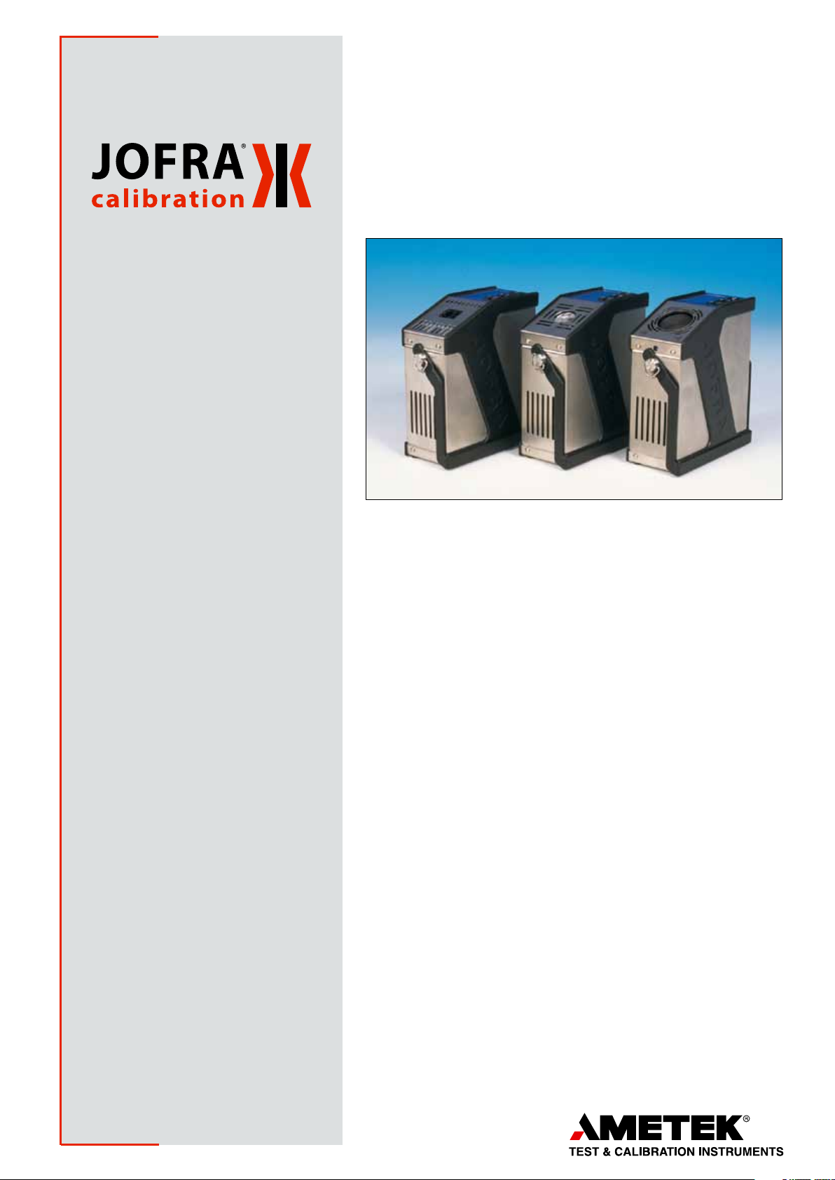
Easy Temperature Calibrator
ETC-series
»
Fully-featured despite the small size
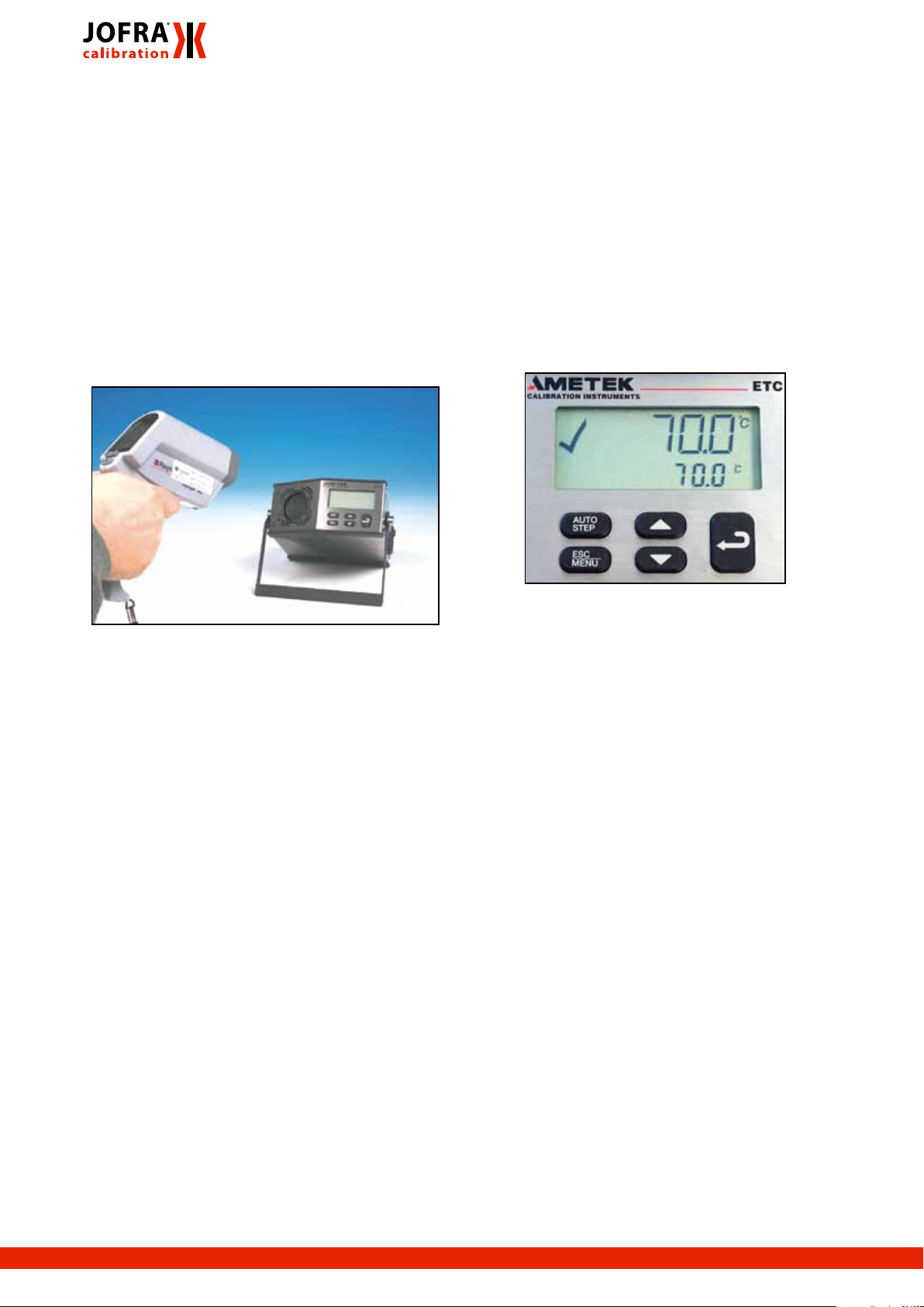
The multi-information display shows actual
and set temperatures, a stability indicator,
and a stability countdown timer
»
Timesaving features
Fast one-key-one-function access to set the
temperature and the auto-stepping function
»
Documentation made easy
RS232 communication interface and
JOFRACAL calibration software are part of
the ready-to-use standard delivery
»
Easy IR calibration
Standard delivery of the ETC-400 R
includes JOFRA IR-LAB software enabling
the user to calibrate IR thermometers with a
fixed emission factor setting
»
Complete marine program
Part of a complete program of marine
approved temperature, pressure and signal
calibrators; including temperature sensors
Heats up by up to 100°C / 212°F per minute and completes a full dualpoint test in less than 10 minutes, including stability time; timesavings at
your fingertips! The ETC- series is designed for field testing of temperature measurement devices.
The small size and light weight make it a perfect instrument to verify sensors in difficult to reach places.
All JOFRA ETC units have many of the same useful and timesaving features offered in the more advanced JOFRA dry-block series.
Designed for people who perform tests and verifications of temperature
sensing devices in the field. This instrument is ideal when time is a critical factor and the highest accuracy is not a critical factor.
Reduced size and weight are important considerations because the unit
is able to fit into a tool box or instrument carrying case and can be used
for sensors that are difficult to access.
One-key-one-function user interface provides immediate access to setting the temperature and the auto-step timesaving function. There is no
need for manipulation of sophisticated menus.
The Stability indicator provides audible and visual prompts when the
temperature is stable. This function also includes a 3 minute countdown
before the stable condition.
Stainless steel and rubber side panels make the instrument suitable for
many years of faithful duty in an industrial environment.
ISO 9001 Manufacturer
Specification Sheet, SS-ETC
Page 2
ETC-400 R for infrared thermometers
The ETC-400 R is designed for optimum speed in connection with calibration of infrared thermometers. The 36 mm
target provides the optimum size for reliable calibration
of infrared thermometers in the process industry as it is
designed for high accuracy and long-term stability while
maintaining speed.
With regard to the coating of the target it has been especially designed for space technology applications, which
secure long time performance under high temperature
influence. In combination with the shape of the target it
ensures the emissivity of 0.96.
If higher accuracy is required, and for recalibration, a 3
mm external JOFRA STS reference probe can be placed
under the surface of the target.
Cooling and heating - ETC-125 A dry-block
The ETC-125 A is a simple yet effective tool for verifying temperature instruments that also require references
below ambient temperatures: e.g. air-conditioning and
cold counters. The predrilled holes allow the use of an
insertion tube in the largest bore. This increases the flexibility to match many sensor-under-test sizes.
Easy-to-use, intuitive operation
All instrument controls are accessed directly from the front
panel. The main functions on the ETC series are designed
with one-key-one-function logic. This means that there are
no difficult multiple keystrokes to remember to access primary functions. The easy-to-read, backlit display features
dedicated icons, which help in identifying instrument conditions and operational steps.
Super fast heating - ETC-400 A dry-block
The ETC-400 A is designed for optimum speed. The heating block is built around a highly efficient heating element.
The insertion holes for the temperature device under
test are located around this element. To reduce mass
and increase effectiveness, there is no removable insertion tube; the holes are drilled directly into the block. The
minimal mass offers an extremely fast heating and cooling
time. The different layouts also make it possible to use an
external JOFRA STS reference probe during the calibration. Choose the combination of holes that best suits your
needs from our various design combinations.
If your application requires a dry-block that can handle
large sensors or more than one sensor at a time, we offer
several other JOFRA dry-block calibrators that can meet
your needs.
Set temperature
The ’’Up’’ and ’’Down’’ arrow keys allow the user to set
the exact temperature desired with a resolution of 0.1°C
or °F.
Instrument setups
The ETC-series stores the complete instrument setup,
including: engineering units, stability criteria, resolution,
auto-step settings, and maximum temperature.
Stability indicator
The bold checkmark on the display indicates that the
calibrator has reached the desired set temperature and is
stable. The operator may change the stability criteria and
establish a greater level of confidence in the calibration
results as desired. A convenient countdown timer is activated three minutes before the unit reaches stability. This
prompts you to be prepared to record results.
2 www.jofra.com Easy Temperature Calibrator • ETC
Page 3
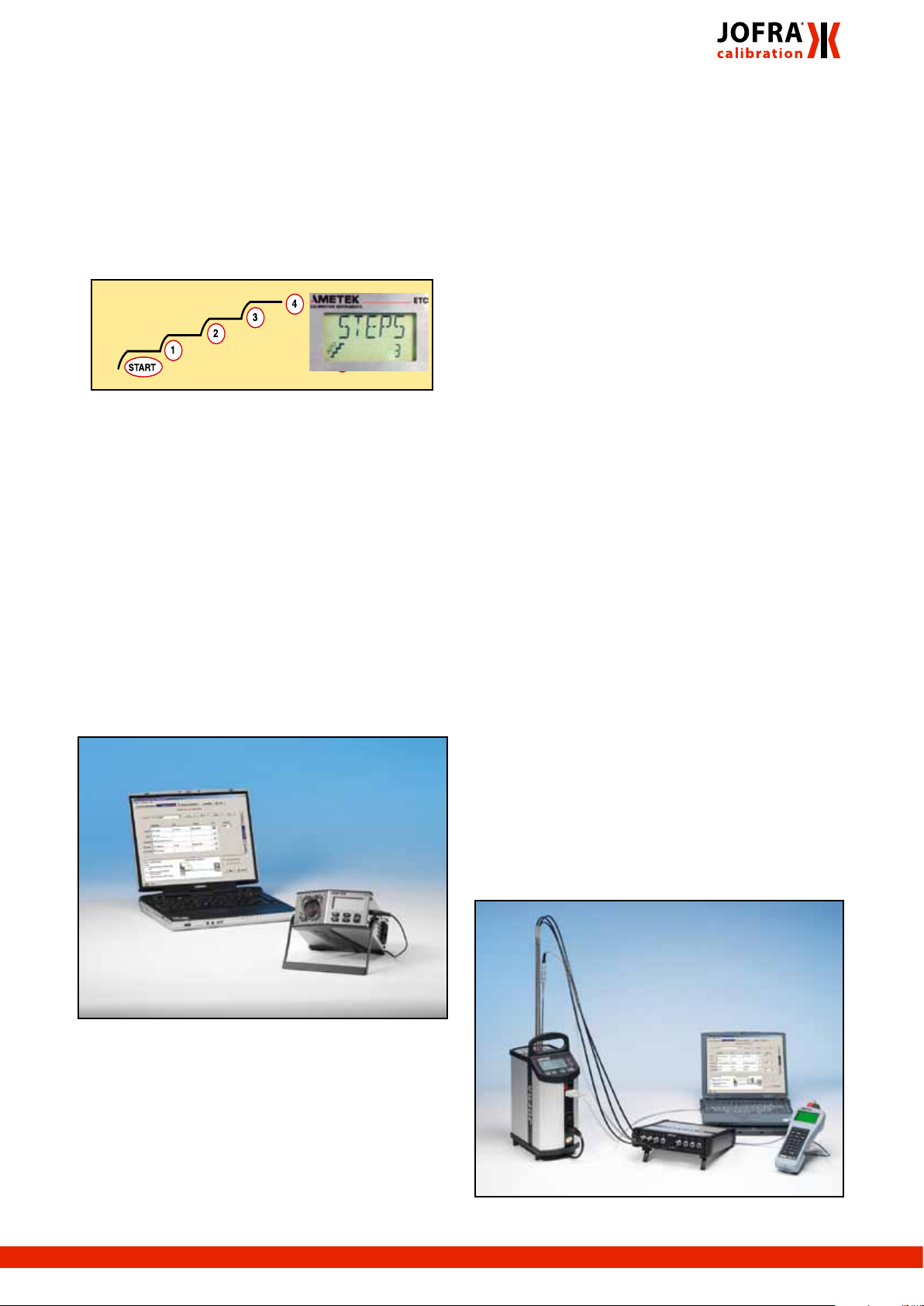
Auto-stepping
This feature saves time. The operator may stay in the control room, or another remote location, monitoring the output from the sensor-under-test while the ETC- series calibrator is placed in the process and automatically changes
the temperature using a programmed step value and rate.
Up to 9 different temperature steps may be programmed,
including the hold time for each step. This feature is also
ideal for burning-in new sensors prior to installation; this
minimizes initial drift and allows for initial testing. It is also
useful for testing temperature data loggers.
Maximum temperature
From the setup menu, you can select a lower maximum temperature limit for the calibrator. This function prevents damage
to the sensor-under-test caused by the application of excessive temperatures.
Re-calibration/adjustments made easy
The ETC- series has a very easy and straightforward procedure for re-calibration/adjustment. There is no need for
a screwdriver or PC software. The only thing you need is
a reliable reference thermometer. Place the probe in the
calibrator and follow the instructions on the display.
JOFRA IR-LAB software for the ETC-400 R
As an extra feature the ETC-400 R will be delivered with
a small mathematical program, which will constitute a
powerful tool together with the calibrator. The program
enables you to calculate at which temperatures you need
to calibrate, if your IR thermometer is either locked to a
fixed emission factor or if you just want to calibrate your
thermometer at a certain emission factor. The program facilitates the whole issue of correcting settings of emission
factors and temperatures.
The calibration surface of the JOFRA ETC-400 R IR
calibrator has an emission factor of 0,96. If your IR-thermometer is using a different emission factor than 0.96,
the result will be a faulty temperature reading on your IR
thermometer. However if your IR thermometer is using an
emission factor of 0.95 or 0.98 – a helpfull diagram is part
of the standard delivery.
Example: Your thermometer is locked to an emission
factor of 0,98 and you have set the JOFRA ETC-400
R to 300°C. The diagram indicates that 3,9°C must be
subtracted from the calibrator temperature, to obtain the
“true” IR thermometer reading (296,1°C).
If you are working with IR thermometers where the emission factor is different than 0.95, 0.96 or 0.98, or other
parameters differ from “standard”, use the PC program
JOFRA IR-Lab. The JOFRA IR-Lab program allows you to
type in various emission factors, in order to get a “true”
temperature readout on your thermometer or the other
way around - what is the true surface temperature of the
calibrator. But the IR-Lab will do more than that; it allows
you to calculate “true” temperatures in simulated surroundings that approximate your actual test environments.
Use the ETC calibrator with JOFRACAL calibration software
Calibration of up to 24 sensors with JOFRA ASM
Using the JOFRA ETC series together with the ASM
Advanced Signal Multi-scanner offers a great time-saving
automatic solution to calibrate multiple temperature sensors at the same time.
The ASM series is an eight channel scanner controlled by
JOFRACAL software on a PC. Up to 3 ASM units can be
stacked to calibrate up to 24 sensors at the same time.
It can handle signals from 2-, 3- and 4 wire RTD’s, TC’s,
transmitters, thermisters, temperature switches and voltage.
www.jofra.com 3ETC • Easy Temperature Calibrator
Page 4

JOFRACAL CALIBRATION SOFTWARE
JOFRACAL calibration software ensures easy calibration
of RTD´s, thermocouples, transmitters, thermoswithes,
pressure gauges and pressure switches. JOFRACAL can
be used with JOFRA DPC-500, APC, CPC and IPI pressure calibrators, all JOFRA temperature calibrators, as well
as JOFRA AMC900, ASC300 multi signal calibrator and
ASM-800 signal multi scanner.
JOFRACAL calibration software may also be used for
manual calibrations, as it can be set up to accept manual
entry of calibration data together with other liquid baths,
ice points or dry-block heat sources.
The calibration data collected may be stored on a PC for
later recall or analysis. The calibrator stores the calibration
procedure and may be taken out to the process site without using a personal computer.
Once all calibrations are completed, the data may be
uploaded to the JOFRACAL calibration software for postprocessing and printing of certificates. The calibration data
collected may be stored on the personal computer for
later recall or analysis.
The JOFRACAL temperature
calibration software may be
donwloaded at www.jofra.com
STANDARD DELIVERY
• JOFRA ETC dry-block calibrator
• Traceable calibration certificate - temperature
performance
• JOFRACAL calibration software
• User and reference manual
• Mains power cable
• Shoulder strap
• RS232 cable
• 1 × predrilled insertion tube (ETC-125 A only)
• Tool for insertion tubes (ETC-125 A only)
• Carrying case (ETC-400 R only) 1)
• JOFRA IR-LAB calibration software (ETC-400 R only)
• Emissivity table (ETC-400 R only)
1) The ETC-400 R is delivered with a carrying case as standard
because it is important to keep dust away from the surface of the
target on the ETC-400 R. The reason being that a clean surface is
important to keep the emissivity and thereby the accuracy. The carrying case is optional for ETC-400 A and ETC-125 A.
ACCESSORIES
122832 Cleaning Brushes - 4 mm - Package of 3 pcs
60F174 Cleaning Brushes - 6 mm - Package of 3 pcs
122822 Cleaning Brushes - 8 mm - Package of 3 pcs
125002 Edgeport Converter with 4 pcs of RS232 ports
124094 Carrying Case for ETC Series
Carrying case (Optional for ETC-125/400 A) 124094
The optional protective carrying case ensures safe transportation and storage of the instrument and all associated
equipment.
JOFRACAL software
Minimum hardware requirements for JOFRACAL calibration software.
TM
• INTEL
• (PENTIUM
• 32 MB RAM (64 MB recommended)
• 80 MB free disk space on hard disk prior to installation
• Standard VGA (800 x 600, 16 colors) compatible screen
• (1024 x 786, 256 colors recommended)
• CD-ROM drive for installation of the program
• 1 free RS232 serial port
4 www.jofra.com Easy Temperature Calibrator • ETC
486 processor
TM
800 MHz recommended)
Page 5

FUNCTIONAL SPECIFICATIONS
Temperature range @ ambient temp. 23°C / 73°F
ETC-125 A
Maximum ........................................................ 125°C / 257°F
Minimum @ ambient temp. 0°C / 32°F ........... -18°C / -0°F
Minimum @ ambient temp. 23°C / 73°F ............ -10°C /14°F
Minimum @ ambient temp. 40°C / 104°F............ 6°C / 43°F
ETC-400 A ......................28 to 400°C / 82 to 752°F@ 23°C
ETC-400 R ......................28 to 400°C / 82 to 752°F@ 23°C
Resolution (user-selectable)
Selectable ............................................................. 1º or 0.1º
Heating time
ETC-125 A
-10 to 23°C / 14 to 73°F .........................................3 minutes
23 to 100°C / 73 to 212°F ....................................11 minutes
100 to 125°C / 212 to 257°F ..................................7 minutes
ETC-400 A / R
28 to 200°C / 82 to 392°F......................................2 minutes
200 to 400°C / 392 to 752°F .................................3 minutes
Cooling time
ETC-125 A
125 to 100°C / 257 to 212°F ................................. 1 minute
100 to 0°C / 212 to 32°F ......................................17 minutes
0 to -10°C / 32 to 14°F .........................................14 minutes
ETC-400 A
400 to 200°C / 752 to 392°F .................................6 minutes
200 to 50°C / 392 to 122°F ..................................15 minutes
ETC-400 R
400 to 200°C / 752 to 392°F .................................9 minutes
200 to 50°C / 392 to 122°F ..................................24 minutes
Stability
ETC-125 A .............................................. ±0.05°C / +0.09°F
ETC-400 A ............................................. ±0.15°C / +0.27°F
ETC-400 R ...............................................± 0.3°C / ± 0.54°F
Measured after the stability indicator has been on for 10 minutes.
Measuring time is 30 minutes.
Time to stability (approximate)
All models .............................................................3 minutes
Accuracy
ETC-125 A ................................................+0.5°C / +0.9°F
1)
ETC-400 A ...............................................+0.5°C / +0.9°F 1)
ETC-400 R .............................................. ±0.5°C / ±0.9°F
2)
ETC-400 R incl. emissivity
.................................... ± 0.4% rdg ±1°C / ±0.4% rdg. ±1.8°F
1) Specification when using the internal reference. (Load 4 mm
OD reference probe in the center of the insert).
2) Specification when using the internal reference. (Load 3 mm
OD reference probe).
Immersion depth
ETC-125 A (insulation included) ................. 110 mm / 4.3 in
ETC-400 A ...................................................105 mm / 4.1 in
Mains specifications
Voltage ETC-125 A ......... Multivoltage 115VAC and 230VAC
.........................................115V(90-132) and 230V(180-264)
Voltage ETC-400 A/R ....... 115V(90-127) or 230V(180-254)
Frequency ETC-125 A ..........................................47 - 63 Hz
Frequency ETC-400 A/R .....................................45 - 65 Hz
Power consumption (max.) ETC-125 A .......................75 VA
Power consumption (max.) ETC-400 A/R .................350 W
KEY FEATURES
Auto stepping
Programmable .................................................Up to 9 steps
Dwell time on each step ............................... Programmable
Multi-information display
Stability indicator ....................................... Clear checkmark
Countdown timer before stable .............................3 minutes
Temperature ....................... SET and READ simultaneously
Alphanumeric messages ................................................ Ye s
Calibration status icons .................................................. Yes
Training mode (heating/cooling block disabled)
Simulation of all functions .............................................. Ye s
Simulating heating and cooling ..... Approx. 100° per minute
Service facilities
Adjustment of the unit from the keypad ......................... Yes
Self explaining guide in display......................................... Yes
Other information: ............................ Display serial number,
.................. software revision level, and last calibration date
Setup facilities
Stability criteria: ......... Extra time before ’’stable indication’’
................................................................................ is shown
Display resolution ............................................. .1° or 1°C/°F
Temperature units ................................................... °C or °F
Slope rate ................................................. 0.1 to 9.9°/minute
Maximum temperature .....................Any value within range
www.jofra.com 5ETC • Easy Temperature Calibrator
Page 6

PHYSICAL SPECIFICATIONS
INSERTS FOR ETC SERIES
Instrument dimensions
ETC-125 A, ETC-400 A and ETC-400 R
L × W × H: ................172 × 72 × 182 mm / 6.8 × 2.8 × 7.2 in
Instrument weight
ETC-125 A ....................................................... 1.8 kg / 3.9 lb
ETC-400 A ......................................................1.6 kg / 3.5 lb
ETC-400 R ...................................................... 1.7 kg / 3.7 lb
Shipping (including shipping cargo box)
ETC-125 A : ......................................................3.0 kg / 6.6 lb
ETC-400 A: .....................................................2.8 kg / 6.2 lb
ETC-400 R ......................................................4.5 kg / 9.9 lb
Size, L × W × H:
ETC-125 A / 400 A: ..............................................................
............................. 345 × 235 × 135 mm / 13.6 × 9.3 × 5.3 in
ETC-400 R ..........425 x 320 x 165 mm / 16.7 x 12.5 x 6.5 in
Miscellaneous
Serial data interface ................................................. RS232
Operating temperature .....................0 to 40°C / 32 to 104°F
Storage temperature ......................-20 to 50
o
C / -4 to 122oF
Humidity ..........................................................0 to 90% RH
Protection class ........................................................... IP-10
DNV Marine Approval, Certificate no ......................A -10 3 84
5-pack, undrilled inserts
Predrilled insert, metric 8 mm
Predrilled insert, imperial 3/8 in
12,5
8 mm
insert
4
6
Metric Type 01
(ETC-125 A)
3
Instruments
Type ETC-125 A ETC-400 A
01 + 02 123939 N/A
01 123938 N/A
02 124045 N/A
1/5
3/8 mm
insert
1/4
5/32
Imperial Type 02
(ETC-125 A)
4
6
2
Metric Multi-hole Type 21
(ETC-400 A)
1/8
1/16
3/ 16
5/32
1/4
Imperial Multi-hole Type 11
(ETC-400 A)
4
3/ 16
1/16
1/8
3/8
1/4
Imperial Multi-hole Type 12
(ETC-400 A)
Type 51
ETC-400 R
36 mm (1.4 in) target
NOTE: All ETC400 calibrators are with fixed inserts. They
can NOT be changed.
6 www.jofra.com Easy Temperature Calibrator • ETC
Page 7

JOFRA STS-103 B
SPECIFICATIONS STS-103 B
It is not easy to make a good quality reference probe. The
main requirement of a reference probe is stability. This
means minimal drift as a function of operating time at the
actual temperature. The less the probe drifts, the lower the
measurement uncertainty.
Especially for the ETC-400 R calibrator JOFRA has
designed a special 3 mm STS reference sensor, the STS103 B. The sensor can be used as a reference sensor
when a higher accuracy is required or for recalibration of
the ETC-400 R. Due to the small immersion depth requirement of the sensor it can be placed under the surface of
the target.
Dimensions
Ref. mm inch
A 150 5.91
B 3 0.12
ORDERING INFORMATION STS-103 B
Order no. Description
Base model number
STS103 Pt100 reference probe, 0°C to 400°C
Diameter of the probe
B Overall diameter 3 mm
Shape and length
150 Straight probe, 150 mm (5.9 in)
Cable length and termination
A Cable 0.5 m (1.6 ft.) + LEMO connector
B Cable 2 m (6.6 ft.) + LEMO connector
C Cable 2 m (6.6 ft.) + Banana plug connectors
Calibration certificate
H Accredited calibration certificate (standard)
F NPL traceable calibration certificate
G NIST traceable calibration certificate
I No certificate - Annealed only
(Useless without calibration certificate /
co-efficients)
S Special calibration certificate
STS103B150AH Sample order number
Reference Pt100 150 mm., cable length
0.5 m (1.6 ft.) with LEMO termination and
accredited certificate
Temperature range
All probes ..................................-50 to 400°C / -58 to 752°F
Accuracy
Hysteresis
Long term stability
Repeatability
Note 1: When used in the range -45 to 400°C / -49 to 752°F.
Note 2: When exposed to 400°C / 752°F for 100 h. Stability will
depend on actual use of the sensor.
1)
@0°C / 32°F .............................. 0.01°C / 0.02°F
2)
@0°C / 32°F ..... typ. 0.014°C / 0.025°F
1)
........................................ 0.005°C / 0.009°F
Sensing element
Type ............................................................................. Pt100
Nominal resistance@0°C / 32°F .................................100 Ω
Length ............................................................ 6 mm / 0.2 in
Temperature coefficient .........................
α
=0.00385 1/°C
100
Minimum immersion depth
STS-103 B (3 mm / 0.12 in): ..........................40 mm / 1.6 in
Self-heating effect
0.06°C/mW / 0.108°F/mW
Response time
τ
(50%) ..............................................................5 seconds
0.5
τ
(90%) ............................................................15 seconds
0.9
Liquid in motion v=0.4m/s.
Electrical connections
Cable ............................................................. 4 wire + shield
Connection ............................................... LEMO goldplated
Insulation resistance
@ 23°C / 73°F ..................................................... 100 Gohm
@ 400°C / 752°F ................................................... 70 Mohm
Outer tube
Inconel 600
Operating conditions
(Probe, connection, and cable) ..............Max. 70°C / 158°F
Storage temperature .....................-20 to 70
o
C / -4 to 158oF
Humidity ..........................................................0 to 90% RH
Protection class (connectors) ................... DIN 40050 IP-50
Shipping dimensions - including carrying case
L x W x H .............. 750 x 140 x 140 mm / 29.5 x 5.5 x 5.5 in
Shipping weight including packing
ST S-103 B ..........................................................2 kg / 4.4 lb
STANDARD DELIVERY
• JOFRA STS-103 B probe
• Cable - according to order number
• Accredited certificate, points:
-45, -20, 0, 50, 100, 200, 400°C
• Plastic carrying case with foam insert
• User manual
www.jofra.com 7ETC • Easy Temperature Calibrator
Page 8

ORDERING INFORMATION
Order no. Description
Base model number
ETC125A ETC-125 A, -10 to 125°C / 14 to 257°F
ETC400A ETC-400 A, 28 to 400°C / 82 to 752°F
ETC400R ETC-400 R, 28 to 400°C / 82 to 752°C
Power supply
115 ETC-400 A/R only: 115 VAC, 50/60 Hz
230 ETC-400 A/R only: 230 VAC, 50/60 Hz
MUL ETC-125 A only: Multi voltage 115 and 230 VAC
Mains power cable type
A European, 230 V,
B USA/Canada, 115 V
C UK, 240 V
D South Africa, 220 V
E Italy, 220 V
F Australia, 240 V
G Denmark, 230 V
H Switzerland, 220 V
I Israel, 230 V
Holes for sensor-under-test
01 ETC125 A - Metric (12.5 mm, 6 mm, 4 mm, 8 mm)
02 ETC125 A - Imperial (1/2 in, 3/8 in, 1/4 in, 5/32 in)
1 1 ET C400 A - I mpe rial (1/16 in, 1/8 in, 5/32 in, 3/16 in, 1/4 in)
12 ETC400 A - Imperial (1/16, 1/8 in, 3/16 in, 1/4 in, 3/8 in)
21 ETC400 A - Metric (2 mm, 3 mm, 4 mm, 6 mm)
51 ETC400 R
Calibration certificate
E NPL and NIST traceable calibration certificate
(standard delivery)
H Accredited calibration certificate
(on quotation basis)
Options
C Carrying case (standard for ETC-400 R)
ETC400A230A21EC Sample order number
JOFRA ETC-400 A series dry-block, 230 VAC power, European power
cord, metric drilled multihole block, standard NPL/NIST traceable certificate and carrying case.
A business unit of AMETEK Measurement & Calibration
AMETEK Test & Calibration Instruments
Technologies Division offering the following industry
leading brands for test and calibration instrumentation.
JOFRA Calibration Instruments
Temperature Calibrators
Portable dry-block calibrators, precision thermometers
and liquid baths. Temperature ranges from
-90°C(-130°F) to 1205°C(2200°F). Temperature sensors
for industrial and marine use.
Pressure Calibrators
Convenient electronic systems ranging from -25 mbar to
1000 bar - fully temperature-compensated for problem-
free and accurate field use.
Signal Instruments
Process signal measurement and simulation for easy
control loop calibration and measurement tasks.
M&G Pressure Tester s & Pumps
Pneumatic floating-ball or hydraulic piston dead weight
testers with accuracies to 0.015% of reading. Pressure
generators delivering up to 1,000 bar.
Lloyd Instruments
Materials testing machines and software from Lloyd
Instruments guarantees expert materials testing
solutions. The comprehensive program also covers
Texture Analysers to perform rapid, general food testing
and detailed texture analysis on a diverse range of foods
and cosmetics.
Davenport Polymer Test Equipment
Allows measurement and characterization of moisture-
sensitive PET polymers and polymer density.
Chatillon Force Measurement
The hand held force gauges and motorized testers
have earned their reputation for quality, reliability and
accuracy and they represent the de facto standard for
force measurement.
Newage Testing Instruments
Hardness testers, durometers, optical systems and
software for data acquisition and analysis.
AMETEK Denmark A/S
Gydevang 32-34 | 3450 Allerød | Denmark
T: +45 4816 8000 | ametek@ametek.dk
Information in this document is subject to change without notice. ©2011, by AMETEK, Inc., www.ametek.com. All rights reserved.
8 www.jofra.com
www.jofra.com
AMETEK Mansfield & Green (North America)
T: +1 800 527 9999 | cal.info@ametek.com
AMETEK Singapore Pte. Ltd. (Singapore)
T: +65 6 484 2388 | aspl@ametek.com.sg
AMETEK Inc. Beijing Rep. Office (China)
T: +86 10 8526 2111 | jofra@ametek.com.cn
AMETEK Instruments India Pvt Ltd. (India)
T: +91 22 2836 4750 | ametek@ametek.dk
AMETEK GmbH (Germany)
T: +49 2159 9136 510 | info.mct-de@ametek.de
AMETEK Calibration Instruments (UK)
T: +44 (0) 1243 833 302 | jofra@ametek.co.uk
Pub code SS-PTC Issue 1109
 Loading...