

Page 1

Reference manual
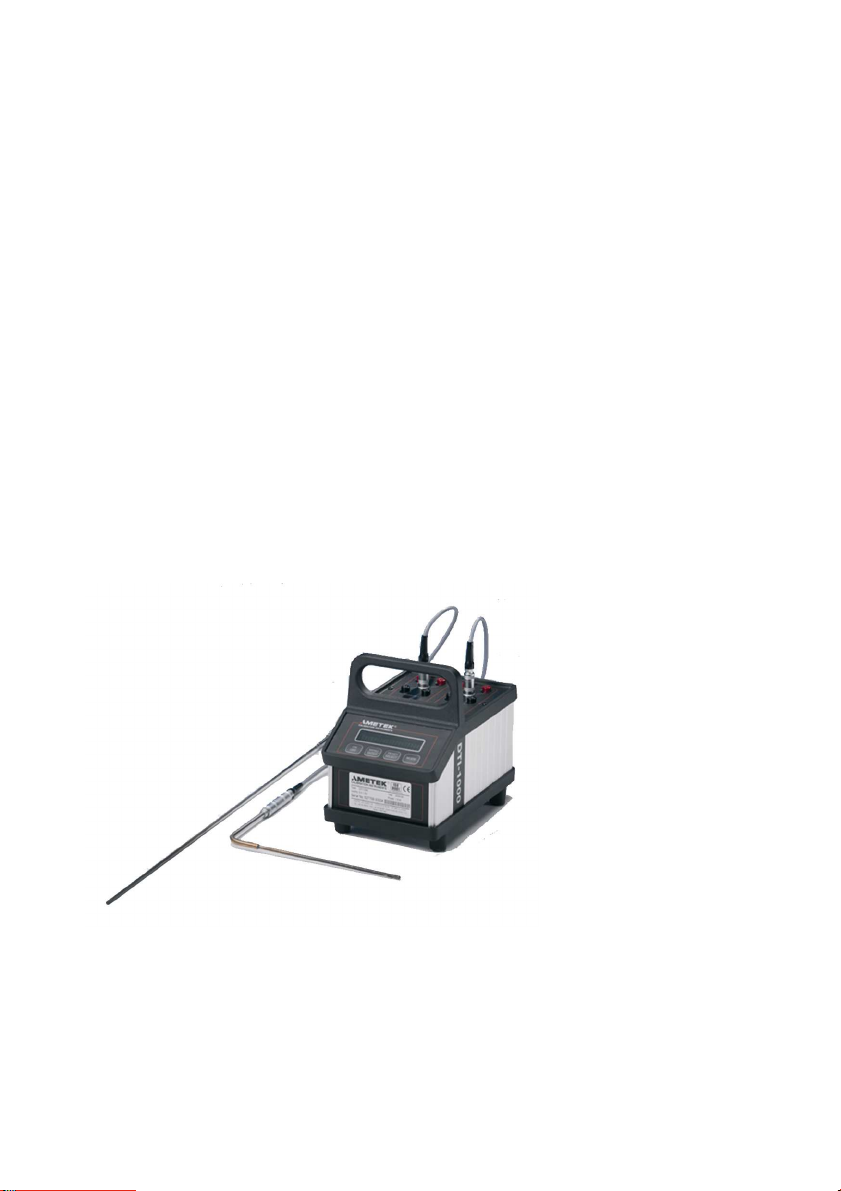
Digital Temperatur Indicator
Jofra DTI-1000 A/B
Page 2
Reference Manual
Digital Temperature Indicator
JOFRA DTI-1000 A/B
Copyright 2005 AMETEK Denmark A/S
Page 3
About this manual….
• The structure of the manual
This reference manual is aimed at users who are familiar with
AMETEK calibrators, as well as those who are not. The manual
is divided into 8 chapters, which describe how to set up,
operate, service and maintain the indicator. The technical
specifications are described as well.
• Safety symbols
This manual contains a number of safety symbols designed to
draw your attention to instructions which must be followed when
using the instrument, as well as any risks involved.
Warning
Conditions and actions which may compromise
the safe use of the instrument and result in
considerable personal injury or material damage.
Caution…
Conditions and actions which may compromise
the safe use of the instrument and result in slight
personal or material damage.
Note…
2 2017-08-10 124745 04
Special situations which demand the user’s
attention.
Page 4

List of contents
1.0 General information ................................................... 4
1.1 Warranty ..................................................................... 5
2.0 Safety instructions ..................................................... 6
3.0 Introduction ................................................................ 8
4.0 Functionality ............................................................... 9
4.1 Functional description ............................................... 11
4.2 Indicators .................................................................. 12
4.3 Touch pad ................................................................ 12
4.4 Connections.............................................................. 13
5.0 Operation .................................................................. 15
5.1 Operating area ......................................................... 15
5.2 Connection of sensors .............................................. 16
5.2.1 Power supply .............................................. 17
5.2.2 On / Off ....................................................... 18
5.2.3 Reset .......................................................... 19
5.2.4 Units ........................................................... 19
5.2.5 Resolution ................................................... 21
5.2.6 Checking sensor coefficients ...................... 23
5.2.7 Mode ........................................................... 27
6.0 Technical specifications .......................................... 28
7.0 Maintenance and display error messages ............ 30
7.1 Maintenance ............................................................. 30
7.2 Changing batteries ................................................... 30
7.3 Display and error messages ..................................... 31
8.0 Adjusting and calibrating the instrument .............. 32
8.1 Introduction to AmeTrim-ATC/DTI Software ............. 32
8.2 Installing the AmeTrim-ATC/DTI Software ................ 33
8.2.1 Connecting the PC and the ATC/DTI .......... 33
8.2.2 Starting the AmeTrim-ATC/DTI
software ...................................................... 34
8.2.3 Reference sensor ........................................ 36
8.2.4 Default values ............................................. 38
8.2.5 RTD input adjustment ................................. 39
8.2.6 Calibration date ........................................... 40
8.2.7 Analog output adjustment ........................... 41
8.3 Setup Printer ............................................................ 44
124745 04 2017-08-10 3
Page 5

1.0 General information
Congratulations on your new JOFRA DTI-1000!
With the AMETEK indicator, you have chosen an extremely effective
instrument which we hope will live up to all your expectations. Over
the past many years, we have acquired extensive knowledge of
industrial temperature calibration. This expertise is reflected in our
products which are all designed for daily use in an industrial
environment. Please note that we would be very interested in hearing
from you if you have any ideas or suggestions for changes to our
products.
This reference manual applies to the following products:
• DTI-1000 A
• DTI-1000 B
ISO-9001 certified
AMETEK Denmark A/S was ISO-9001 certified in September
1994 by Bureau Veritas Certification Denmark.
CE-label
* DTI-1000 A / DTI-1000 B from serial no. xxxxxx-00541
4 2017-08-10 124745 04
Your new temperature calibrator bears the CE label
and conforms to the Electromagnetic Compatibility
(EMC) Directive 2014/30/EU and the Low Voltage
Directive 2014/35/EU and RoHS Recast (RoHS II)
Directive 2011/65/EU*.
Page 6

Technical assistance
Please contact the dealer from whom you acquired the instrument if
you require technical assistance.
1.1 Warranty
This instrument is warranted against defects in workmanship,
material and design for two (2) years from date of delivery to the
extent that AMETEK will, at its sole option, repair or replace the
instrument or any part thereof which is defective, provided, however,
that this warranty shall not apply to instruments subjected to
tampering or, abuse, or exposed to highly corrosive conditions.
THIS WARRANTY IS IN LIEU OF ALL OTHER WARRANTIES
WHETHER EXPRESS OR IMPLIED AND AMETEK HEREBY
DISCLAIMS ALL OTHER WARRANTIES, INCLUDING, WITHOUT
LIMITATION, ANY WARRANTY OF FITNESS FOR A PARTICULAR
PURPOSE OR MERCHANTABILITY. AMETEK SHALL NOT BE
LIABLE FOR ANY INCIDENTAL OR CONSEQUENTIAL DAMAGES,
INCLUDING, BUT NOT LIMITED TO, ANY ANTICIPATED OR LOST
PROFITS.
This warranty is voidable if the purchaser fails to follow any and all
instructions, warnings or cautions in the instrument’s User Manual.
If a manufacturing defect is found, AMETEK will replace or repair the
instrument or replace any defective part thereof without charge;
however, AMETEK’s obligation hereunder does not include the cost
of transportation, which must be borne by the customer. AMETEK
assumes no responsibility for damage in transit, and any claims for
such damage should be presented to the carrier by the purchaser.
124745 04 2017-08-10 5
Page 7
2.0 Safety instructions
Read this manual carefully before using
the instrument!
Please follow the instructions and procedures
described in this manual. They are designed to allow
you to get the most out of your DTI system and avoid
any personal injuries and/or damage to the instrument.
Disposal – WEEE Directive
These calibrators contain Electrical and Electronic
circuits and must be recycled or disposed of properly
(in accordance with the WEEE Directive 2012/19/EU).
Warning
• The indicator must not be used for any purposes
other than those described in this manual, as it
might cause a hazard.
• The indicator has been designed for indoor use
only and is not to be used in wet locations.
• The indicator is not to be used in hazardous
areas, where vapour or gas leaks, etc. may
constitute a danger of explosion.
• The indicator is not designed for operation in
altitudes above 2000 meters.
• Only use the specified mains adaptor approved for
the voltage and plug configuration in your area.
• Do not connect rated voltages to earth with a
maximum above 30V to the input terminals.
• Always position the indicator to enable easy and
quick disconnection of the power source (mains
adaptor).
6 2017-08-10 124745 04
Page 8

Caution…
When connecting the PC and the indicator please
ensure that both the PC and the indicator are switched
off at the mains. Failure to do so may result in your
equipment being damaged.
124745 04 2017-08-10 7
Page 9

3.0 Introduction
The DTI (Digital Temperature Indicator) system is designed for fast
and traceable calibration. The system is portable.
The DTI is prepared for re-calibration by your local calibration
laboratories, and all necessary instructions for the re-calibration is
stated in this manual.
The DTI is a precision instrument and to achieve the precision, a set
of sensor coefficients relating to the specific sensor must be present
in the DTI. Before use of the DTI, ensure that the correct coefficients
for each channel in the DTI are equal to those from the sensors
calibration certificate – see section 5.2.6.
How to install new sensor coefficients can be found in section 8.2.3.
Definitions and terminology used in this manual:
a. Text inside <> refer to soft-keys on the DTI panel or keys on
Text with big letters indicate the activated function if there
b. Display text on the DTI is shown inside rounded frames.
c. Screen menus in the DTI software are shown inside edged
Note…
The DTI is not designed for continuously data-logging
recording, since there is no guarantee for missed log
values during the data-logging
the PC keyboard.
are more than one function (example <ON/Off>).
frames.
8 2017-08-10 124745 04
Page 10
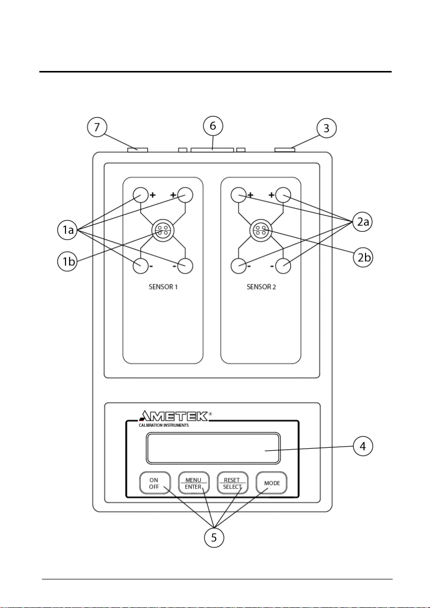
4.0 Functionality
Overview:
124745 04 2017-08-10 9
Page 11

POS Description
1a Sensor 1 connections
1b Sensor 1 connections
2a Sensor 2 connections
2b Sensor 2 connections
3 Ground terminal for cable shields
4 Display with 2 * 20 characters
5 Soft keys
6 RS232 connector
7 Power inlet for mains adapter
10 2017-08-10 124745 04
Page 12

4.1 Functional description
The DTI is used for measuring inputs from two RTD sensors. The two
sensors are connected to the connectors in the top plate. The input
signal is compared to the two internal resistor references from which
the input signal can be determined.
The DTI operates with a 2*20 character display, which continuously
read out the two inputs.
The input value can be shown as the actual read value for both
sensors, the peak values for sensor 1 or 2, the differential value for
the two sensors or as the differential peak value for the two sensors.
The input value can be shown in Ω, °C, °F or K selected by the user.
The resolution in temperature can be 0.1, 0.01 or 0.001.
The sensor coefficients can be inspected by the user and changed in
the software program.
The power supply is made by eight 1.5 Volt batteries or a mains
adapter. Use only mains adapter supplied by AMETEK in order to
comply with the requirements in EN50081-1 (1992) and EN50082-1
(1992).
It is possible to connect the shields from the cables to the cabinet, in
order to reduce the influence of noise.
The DTI-1000 is supplied with RS232 and software, in order to have
the possibility of saving the measured data and to recalibrate the DTI
or the sensors.
124745 04 2017-08-10 11
Page 13
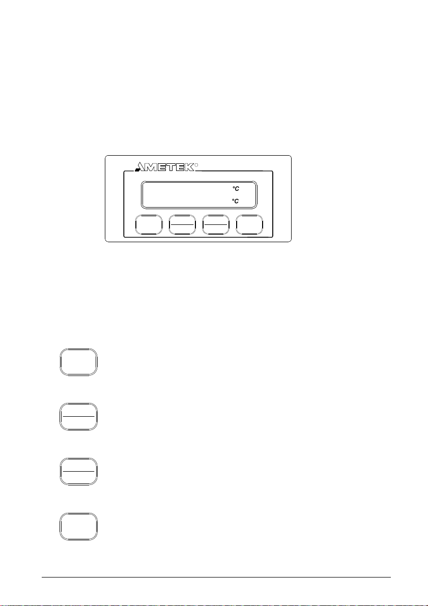
4.2 Indicators
The DTI only uses the display for all indications. The display has 2*20
characters which will swap between read-out values or menu
selection when requested. Please see section 5.2.1 to 5.2.7 for
possible display read-outs. Please note that the error messages will
also be showed in the display, see section 7.3.
CALIBRATION INSTRUMENTS
T1
T2
ON MENU RESET
R
23.65
23.60
ENTEROFF
SELECT
MODE
4.3 Touch pad
There are 4 soft-keys on the touch pad panel, where 2 of the softkeys have a double function.
ON
OFF
Switch ON or switch OFF the DTI. Please press
down the key at least 0.2 seconds in order to switch
on the unit.
MENU toggles between the menus:
MENU
ENTER
Mode/Unit/Resolution/Sensor
ENTER enters the menu function selected with the
RESET/SELECT key.
RESET
SELECT
RESET resets peak values for both channels.
SELECT toggles between the selected menu
functions.
Toggles between the following display modes: T1/T2,
MODE
Diff(T1-T2), T1MAX./T1MIN., T2 MAX./T2 MIN., DIFF
MAX./DIFF MIN.
12 2017-08-10 124745 04
Page 14
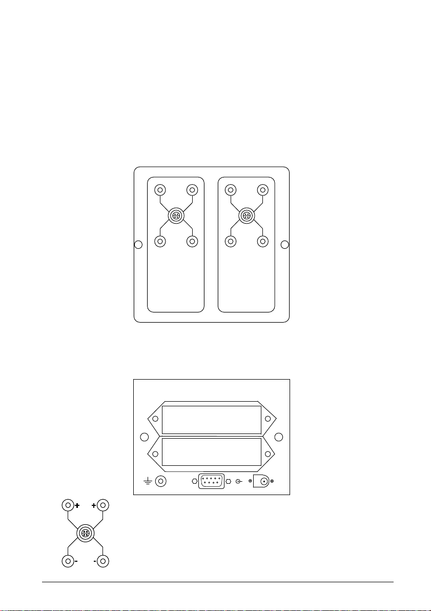
4.4 Connections
All signal cables have to be connected to the top plate (grounding on
the back plate).
Power and communication cables have to be connected on the back
plate.
Top plate connections
+
+ +
+
-
-
SENSOR 1 SENSOR 2
-
-
Back plate connections
2 x 4 PCS BATTERIES TYPE AA
Connections for sensors, where channel 1 is
RS 232
9VDC
200 mA
-
shown.
Please note that the LEMO-connector is only
available on the DTI-1000 model.
SENSOR 1
124745 04 2017-08-10 13
Page 15

RS 232
9VDC
200 mA
Ground terminal for shield on the signal cables.
-
Power input for mains adapter 9VDC 200mA.
Connector for RS232C interface.
14 2017-08-10 124745 04
Page 16

5.0 Operation
5.1 Operating area
Both of the DTI models are intended for use in areas which meet the
following:
Temperature range : 0°C to 50°C (32°F to 122°F)
Humidity : 0% to 90%
Protection class : IP20
Warning
• The indicator must not be used for any purposes other
than those described in this manual, as it might cause a
hazard.
• The indicator has been designed for indoor use only
and is not to be used in wet locations.
• The indicator is not to be used in hazardous areas,
where vapour or gas leaks, etc. may constitute a
danger of explosion.
124745 04 2017-08-10 15
Page 17

5.2 Connection of sensors
The sensor should be connected to the terminals as shown in the
figure below:
Use the ground terminal (see the figure "Overview" section 4, pos. 3)
for the cable shields in order to reduce noise.
The connector type to extra connector on DTI-1000 is: LEMO FFA 1S
304 CNAC.
16 2017-08-10 124745 04
Page 18

5.2.1 Power supply
The DTI is supplied with 8 1.5 Volt batteries as standard. When the
battery voltage is low following message will appear:
BATTERY LOW
PRESS ANY KEY
This message will only appear one time after the DTI has been
switched on, and is removed by pressing the key <Menu/Enter> or
<Reset/Select>. The DTI is still able perform accurate measurements
a little while longer.
The batteries are placed in the two battery holders shown in the
figure below:
It is also possible to supply the DTI from a mains adapter at the
connector shown in the figure above. The mains adapter can be
supplied by AMETEK.
2 x 4 PCS BATTERIES TYPE AA
RS 232
9VDC
200 mA
-
Mains adapter
124745 04 2017-08-10 17
Page 19

5.2.2 On / Off
Start the DTI by activating the softkey <ON/Off>. Following message
will be shown in the display:
SELF-CALIBRATION
AND TESTING 1
This information states that the internal references and the sensor
coefficients are checked. If the coefficients are incorrect an error
message will occur which is described in section 7.3.
The next message shown in the display will be:
SELF-CALIBRATION
AND TESTING 2
In this step the A/D converter is calibrated which approximately takes
1 second. When the calibration is over following message will be
shown:
SELF-CALIBRATION
AND TESTING 3
Test 3 is an internal voltage reference check, which approximately
takes 4 seconds.
When all tests have succeeded, the DTI will show the model type and
last calibration date in the display:
Ver. X.XX DTI-1000
CAL. DATE 031216
18 2017-08-10 124745 04
Page 20

After this the input values will be shown in the display in the same
format, as before the DTI was shut off last time:
T1 23.65 °C
T2 23.60 °C
If there is no input signal or it is outside the measuring range a
hyphen will be shown for that specific channel.
5.2.3 Reset
Use the softkey <RESET/Select> in order to reset the peak values in
the selected difference mode.
5.2.4 Units
In order to change the unit of the read-out, you must press the
softkey <MENU/Enter> 1 time. The following message will be shown
in the display:
UNIT: °C
124745 04 2017-08-10 19
Page 21

Use the softkey <Reset/SELECT> to scroll between following types
of units:
UNIT SELECTION MENU READ-OUT MODE
UNIT: °C T1 23.65 °C
T2 23.60 °C
│
UNIT: °F T1 74.57 °F
T2 74.48 °F
│
UNIT: Ω R1 109.210 Ω
R2 109.191 Ω
│
UNIT: K T1 296.80 K
T2 296.75 K
Use the softkey <Menu/ENTER> to select the specific read-out unit.
Please note that read-out in Ω has one more digit than specified in
the resolution set-up.
20 2017-08-10 124745 04
Page 22

5.2.5 Resolution
In order to change the resolution on the read-out, you must press the
softkey <MENU/Enter> 2 times. The following message will be shown
in the display:
RESOLUTION: 0.01
Use the softkey <Reset/SELECT> to scroll between following types
of resolution:
RESOLUTION SELECTION MENU READ-OUT MODE
RESOLUTION: 0.01 T1 23.65 °C
T2 23.60 °C
│
RESOLUTION: 0.001 T1 23.651°C
T2 23.599°C
│
RESOLUTION: 0.1 T1 23.7 °C
T2 23.6 °C
Use the softkey <Menu/ENTER> to select the specific read-out unit.
124745 04 2017-08-10 21
Page 23

The sample period is dependent on the selected resolution which can
be longer than sample rate to the display if a resolution above 0.1 is
selected. The sample rates for the different resolutions are shown
below:
Resolution 0.1 0.01 0.001
Sample period 2 s 3 s 12 s
Please note that read-out in Ω has one more digit than specified in
the resolution set-up.
22 2017-08-10 124745 04
Page 24

5.2.6 Checking sensor coefficients
In order to check the sensor ID and coefficients on the DTI, press the
softkey <MENU/Enter> 4 times.
If Callendar van Dusen coefficients is used for the sensor, the
following message will be shown in the display:
SENSOR 1: 9402244
R0 : 1.0000000E+02
Use the softkey <Reset/SELECT> to scroll through the coefficients:
(example with both sensors using default coefficients)
SENSOR 1: 9402244 SENSOR 2: 9402246
R0 : 1.0000000E+02 R0 : 1.0000000E+02
│ │
SENSOR 1: 9402244 SENSOR 2: 9402246
A : 3.9080200E-03 A : 3.9080200E-03
│ │
SENSOR 1: 9402244 SENSOR 2: 9402246
B : -5.8020000E-07 B : -5.8020000E-07
│ │
SENSOR 1: 9402244 SENSOR 2: 9402246
C : -4.2735000E-12 C : -4.2735000E-12
124745 04 2017-08-10 23
Page 25

Use the softkey <Menu/ENTER> to leave this menu.
The coefficients are used in the equations:
= R(t)
Below 0°C:
Above 0°C:
If ITS-90 coefficients is used for the sensor, the following message
will be shown in the display:
R
0
= R(t)
R
0
B+tA+(1
B+tA+(1
t
2
)
⋅⋅⋅
t
⋅⋅⋅⋅
32
100)-(tC+
)
t
CH1: 9402244
RTPW: 1.0000000E+02
Use the softkey <Reset/SELECT> to scroll through the coefficients:
(example with both sensors using default coefficients)
24 2017-08-10 124745 04
Page 26

CH1: 9402244 CH2: 9402245
RTPW: 1.0000000E+02 R0 : 1.0000000E+02
│ │
CH1: 9402244 CH2: 9402245
aLR: 0.000000E-00 aLR: 0.000000E-00
│ │
CH1: 9402244 CH2: 9402245
bLR: 0.000000E-00 bLR: 0.000000E-00
│ │
CH1: 9402244 CH2: 9402244
cLR: 0.000000E-00 cLR: 0.000000E-00
│ │
CH1: 9402244 CH2: 9402245
aHR: 0.000000E-00 aHR: 0.000000E-00
│ │
CH1: 9402244 CH2: 9402245
bHR: 0.000000E-00 bHR: 0.000000E-00
│ │
CH1: 9402244 CH2: 9402245
cHR: 0.000000E-00 cHR: 0.000000E-00
│ │
CH1: 9402244 CH2: 9402245
dHR: 0.000000E-00 dHR: 0.000000E-00
124745 04 2017-08-10 25
Page 27

Use the softkey <Menu/ENTER> to leave this menu.
Use the table below to convert ITS90 coefficient nomination to DTI-
1000 nomination.
ITS90 Subrange
3 4 5 6 7 8 9 10 11
aLR a3 a4 0
bLR b3 b4 0
cLR c3 0 0
aHR a5 a6 a7 a8 a9 a10 a11
bHR b5 b6 b7 b8 b9 0 0
cHR 0 c6 c7 0 0 0 0
DTI-1000
coefficient
dHR 0 d 0 0 0 0 0
26 2017-08-10 124745 04
Page 28

5.2.7 Mode
In order to change the reading, you must press the softkey <MODE>
to scroll between following types of read-out:
READ-OUT MODE
T1 23.65 °C
T2 23.60 °C
DIFF (T1-T2)
0.05 °C
T1MAX. 23.66 °C
T1MIN. 23.64 °C
T2MAX. 23.61 °C
T2MIN. 23.59 °C
DIFFMAX. 0.07 °C
DIFFMIN. 0.03 °C
124745 04 2017-08-10 27
Page 29

6.0 Technical specifications
Electrical specifications
Measuring input: : 2 channels for 4 wire RTD sensors
Measuring range DTI-1000 A : 0 to 360 Ω (-200 to 750°C / -328 to
1382°F)
Measuring range DTI-1000 B : 0 to 95 Ω (-200 to 750°C / -328 to
1382°F)
Accuracy DTI-1000 A : ±6 ppm rdg + 1,4 mΩ (12 months use)
Accuracy DTI-1000 B : ±6 ppm rdg + 0,7 mΩ (12 months use)
Measuring current : 1mA, 18% duty cycle
Temperature coefficient : ± 0.8 ppm/°C. outside 23±3°C (73.4±
5.4°F)
Temperature resolution : 0.1 / 0.01 / 0.001.
Units : °C / °F / Ω / K.
Supply : 8 pcs. 1.5 V type AA batteries or 9 V
mains adapter.
Battery life : 15 hours
Mechanical specifications
Weight : 2.2 kg. / 4.9 lb.
Dimensions (H/W/D) : 195 mm / 135 mm / 225 mm.
7.7 in. / 5.3 in. / 8.9 in.
Operating conditions :
Temperature range : 0 to 50 °C (32 to 122°F)
Humidity range : 0 to 90 %
Protection class : IP20
Storage temperature : -20 to 60°C (-4 to 140°F)
28 2017-08-10 124745 04
Page 30

Mechanical specifications
Electromagnetic : Designed for use in controlled
environment electromagnetic environment as defined
EN61326-1 2013.
Additional data - directives observed
The following standards are
observed according to the EMCDirective (2014/30/EU)
EN 61326-1: 2013: Electrical
equipment for measurement, control
and laboratory use – EMC
requirements.
124745 04 2017-08-10 29
Page 31

7.0 Maintenance and display error
messages
7.1 Maintenance
The DTI does not require specific maintenance before or after use.
The user may carry out the following procedures himself.
Cleaning surfaces Use alcohol or water and a soft cloth.
Re-calibrate or change Use the software in order to re-
coefficients for sensors calibrate/change the sensor
coefficients (see section 8.0).
Re-calibration of DTI Use the calibration routines in the
references or analog out software to re-calibrate the DTI (see
section 8.0).
7.2 Changing batteries
The batteries are placed in the two battery holders shown in the
figure below. The battery holders can be pulled out by pressing the
locks on both sides simultaneously.
2 x 4 PCS BATTERIES TYPE AA
RS 232
30 2017-08-10 124745 04
9VDC
200 mA
-
Press
Page 32

7.3 Display and error messages
If the DTI detects an error while running, it will automatically appear
in the display. Following error messages can occur:
Display message: Meaning/Action:
BATTERY LOW Battery voltage low.
PRESS ANY KEY Change batteries
(section 7.2).
No sensor connected to input
T1 ////.///°C or measuring input outside
T2 ////.///°C range.
Downloaded coefficients
CONSTANT ERRORS rejected.
DEFAULT VALUES Check calibration.
Default sensor coefficients
used are:
R0: +100.000000
A:+3.90802E-3
B : -5.80200E-7
C : -4.27350E-12
Press any key to continue
124745 04 2017-08-10 31
Page 33

8.0 Adjusting and calibrating the
instrument
You are advised to return the DTI-1000 A/B to AMETEK Denmark
A/S or an accredited laboratory at least once a year for calibration.
Alternatively you can calibrate/adjust the DTI-1000 A/B yourself using
the AmeTrim-ATC/DTI Adjust and Calibration software. AmeTrimATC/DTI also supports DTI-100 and DTI-1000 manufactured in 1996
or later or with firmware version 1.60 or later. This software is divided
into 5 different processes:
• Reference sensor: Use this feature to manage the
coefficients of the sensors in the DTI.
• Set to default values: Use this feature to set internal
reference resistor values to default values if odd values have
been downloaded.
• RTD-input adjustment: Use this feature to calculate and
download new values for internal reference resistors.
• Calibration date: Use this feature to download a new
calibration date to the DTI.
• Analog output adjustment: Use this feature to adjust the
analog output (only DTI-1000 with firmware version 1.60 or
earlier).
8.1 Introduction to AmeTrim-ATC/DTI Software
This software is supplied on the JOFRACal CD-ROM. It can be run
directly from this CD-ROM and requires no special installation.
It is possible to make a disk containing the AmeTrim-ATC/DTI
software. From this disk AmeTrim-ATC/DTI can be installed on the
harddisk of the computer, but the disk has to be in the disk drive
when running the software.
To use the software, you need:
32 2017-08-10 124745 04
Page 34

PC hardware requirements
• IBM compatible PC with 486 or higher processor (PentiumTM 200
MHz recommended).
• 32 MB of RAM (64 MB recommended).
• 4 MB available hard-disk space.
• Standard VGA monitor (800 x 600, 256 colours), (1024 x 768
recommended).
• CD-ROM drive.
• One vacant RS 232 Serial Port.
PC software requirements
• Microsoft Windows®98, Microsoft Windows® NT 4.0, Microsoft
Windows® 2000, Microsoft Windows® ME, Microsoft Windows®
XP.
• System font: MS Sans Serif and Arial.
8.2 Installing the AmeTrim-ATC/DTI Software
The software comes on a CD-ROM and is ready to run – no
installation is required. Simply insert the CD-ROM and run the
ATC/DTI-adjustment program.
8.2.1 Connecting the PC and the ATC/DTI
Caution…
1. Ensure that both the PC and the ATC/DTI are switched
off at the mains. Failure to do so may result in your
equipment being damaged.
2. Connect the serial cable provided to the “RS 232” port on
the back of the DTI and to the COM port on the PC.
3. Switch on the PC and the DTI.
124745 04 2017-08-10 33
Page 35

8.2.2 Starting the AmeTrim-ATC/DTI Software
ATC/DTI software.
Note…
Before starting this software, the PC and the ATC/DTI must
be connected together and the indicator switched on (see
section 8.2.1).
The ATC must not be performing any tasks like switch test,
auto step or workorders. That means that the ATC must be
in the main menu before starting the software.
Use the normal Windows procedure to start the AmeTrim-
If you are unsure on how to start software programs, refer to
your Windows Help
34 2017-08-10 124745 04
Page 36

In the main menu select “Run Program” to start the calibration.
Select “DTI” and “Comport” in the “Device Quick Connect” dialog box
and press “Connect”. If the DTI is not switched on or is not connected
to the selected port, then the software returns to the AmeTrim
adjustment software main menu.
As the software starts, it detects the type of calibrator connected to
the PC and reads its serial number. This information is displayed at
the bottom of the DTI main menu window
124745 04 2017-08-10 35
Page 37

A new dialogue with a table containing the coefficients
8.2.3 Reference sensor
This option enables you to view the calibration values currently
loaded in the DTI for the reference sensors as well as enter and
download values for new reference sensors. In addition to the
equipment already described in sections 8.1 and 8.2.1, you also
require the calibration certificate for the new reference sensor.
In DTI main menu, click “Sensor coefficients”.
stored in the DTI for sensor 1 and sensor 2. Current sensor
coefficients are automatically uploaded.
36 2017-08-10 124745 04
Page 38

124745 04 2017-08-10 37
Page 39

To enter values for a new reference sensor
Click a radio button to select sensor 1 or sensor 2. And
press “Upload” to read current coefficients.
8.2.4 Default values
This option downloads a set of default values, which are stored in the
AmeTrim-ATC/DTI software.
Type in a unique and descriptive name for the reference
sensor.
Use the mouse to position the pointer in the boxes in the
table.
Select “ITS-90” or “Callendar van Dusen coefficients” and
type in the coefficients from the Calibration Certificate
supplied with the reference sensor.
When all the values from the Calibration Certificate have
been entered, click “Download” values.
When the values are downloaded they overwrite the ones
stored in the indicator.
Note…
These coefficients are not saved. Therefore, they must be
typed in and downloaded when they need to be used.
Press “Yes” to download default values to the DTI.
38 2017-08-10 124745 04
Page 40

8.2.5 RTD input adjustment
This option allows you to adjust the DTI by calculating and
downloading new values for the internal reference resistors.
For adjusting the internal reference resistors, you need the following:
DTI-100 / DTI-1000 / DTI-1000 A :
50 ohm resistor
350 ohm resistor
DTI-1000 B :
12 ohm resistor
85 ohm resistor
It is recommended to use resistors with an accuracy of 6 ppm or
better.
124745 04 2017-08-10 39
Page 41

Connect the reference resistors to the input channels and enter the
resistor values. Press “Start measurement”, wait until the readings for
“New low reference value” and “New high reference value” have
stabilized (approx. 2 minutes) and press “Lock new values” to stop
the measurement. The locked values can now be downloaded to the
DTI or cancelled.
8.2.6 Calibration date
This option allows you to change the calibration date without
adjusting the DTI.
Select the date of calibration and press “Download”.
40 2017-08-10 124745 04
Page 42

8.2.7 Analog output adjustment
(only DTI-1000 with firmware ver. 1.60 or earlier).
This option allows you to adjust the analog output of the DTI-1000.
For adjusting the analog output you need a voltmeter 0V to 5V range
with 0.1mV resolution and an accuracy of 0.1 mV.
After entering the DTI analog output adjustment window, press “Start”
to begin the adjustment procedure.
124745 04 2017-08-10 41
Page 43

Measure the output voltages of the two analog outputs, enter the
values and press “Next”.
42 2017-08-10 124745 04
Page 44

Repeat the measurement of the output voltage for high output, enter
the values and press “Next”.
Press “Yes” to download calibration date and then “Exit” to return to
the main menu.
124745 04 2017-08-10 43
Page 45

8.3 Setup Printer
This option provides a standard Windows procedure which enables
you to edit the settings for the current printer or change to another
printer.
If you are unsure how to use these settings, refer to your Windows
Help.
44 2017-08-10 124745 04
Page 46

AMETEK Sensors, Test & Calibration
A busine ss unit of AME TEK Measure ment &
Calibration Technologies Division offering the
followi ng industry leading bran ds for test and
Portable dry-block calibrators, precision
therm ometers and li quid baths. Tempe rature
Conveni ent electro nic systems ra nging from
-25 mbar to 100 0 bar - fully temp erature-
compensated for problem-free and accurate
Process signal mea surement an d simulation fo r
easy control loop cal ibration and m easuremen t
Pneumatic floating-ball or hydraulic piston dead
weight te sters with ac curacies to 0.015% of
readin g. Pressure ge nerators de livering up to
Digital pressure g auges and cal ibrators tha t are
accurate, easy-to-u se and reliable. Designed for
use in the h arshest env ironments ; most products
Materials testing machines and software that
guara ntees exper t materials te sting soluti ons.
Also covering Texture Ana lysers to per form rapid,
gener al food testin g and detaile d texture analysis
on a diver se range of foods and cosmetics.
Allows measuremen t and characte rization of
moisture-sensitive PET polymers and polymer
The han d held force gau ges and motorized
tester s have earned th eir reputation for qualit y,
reliab ility and acc uracy and they r epresent th e de
facto standard for force measurement.
Hardness testers, durometers, optical systems
and sof tware for dat a acquisitio n and analysi s.
calibration instrumentation.
JOFRA Calibration Instruments
Temperature Calibrators
sensors for industrial and marine use.
M&G Deadweig ht Testers & Pu mps
carr y an IS, IP67 and DN V rating.
Davenport Polymer Test Equipment
Chatillon Force Measurement
Pressure Calibrators
field use.
Signal Instruments
tasks.
1,000 bar.
Crystal Pressure
Lloyd Materials Testing
densit y.
Newage Hardness Testing
www.ametekcalibration.com
United Kingdom
Tel +44 (0)1243 833 302
caluk.sales@ametek.com
France
Tel +33 (0)1 30 68 89 40
general.lloyd-instruments@ametek.fr
Germany
Tel +49 (0)2159 9136 510
info.mct-de@ametek.de
Denmark
Tel +45 4816 8000
jofra@ametek.com
Information in this document is subject to change without notice. ©2016, by AMETEK, Inc., www.ametek.com. All rights reserved.
USA
Florida
Tel +1 (800) 527 9999
cal.info@ametek.com
California
Tel +1 (800) 444 1850
crystal@ametek.com
India
Tel +91 22 2836 4750
jofra@ametek.com
Singapore
Tel +65 6484 2388
jofra@ametek.com
China
Shanghai
Tel +86 21 5868 5111
Beijing
Tel +86 10 8526 2111
jofra.sales@ametek.com.cn
 Loading...