

Page 1

DLM-E 3kW & 4kW
Series Power
Supplies
Operation Manual
This manual covers models:
3kW 4kW
DLM5–350E DLM5–450E
DLM8–350E DLM8–450E
DLM16–185E DLM16–250E
DLM32–95E DLM22-180E
DLM40–75E DLM32–125E
DLM60–50E DLM40–100E
DLM80–37E DLM60–66E
DLM150–20E DLM80–50E
DLM300–10E DLM150–26E
DLM600–5E DLM300–13E
DLM600–6.6E
M362000-01 Rev E www.programmablepower.com
Page 2

Page 3

Page 4

Page 5

ABOUT AMETEK
AMETEK Programmable Power, Inc., a Division of AMETEK, Inc., is a global leader in the design and
manufacture of precision, programmable power supplies for R&D, test and measurement, process control,
power bus simulation and power conditioning applications across diverse industrial segments. From bench
top supplies to rack-mounted industrial power subsystems, AMETEK Programmable Power is the proud
manufacturer of Elgar, Sorensen, California Instruments and Power Ten brand power supplies.
AMETEK, Inc. is a leading global manufacturer of electronic instruments and electromechanical devices
with annualized sales of $2.5 billion. The Company has over 11,000 colleagues working at more than 80
manufacturing facilities and more than 80 sales and service centers in the United States and around the
world.
Trademarks
AMETEK is a registered trademark of AMETEK, Inc.
Other trademarks, registered trademarks, and product names are the property of their respective owners
and are used herein for identification purposes only.
Notice of Copyright
DLM-E 3kW & 4kW Series Power Supplies Operation Manual
Inc. All rights reserved.
© 2002-2011AMETEK Programmable Power,
Exclusion for Documentation
UNLESS SPECIFICALLY AGREED TO IN WRITING, AMETEK PROGRAMMABLE POWER, INC.
(“AMETEK”):
(a) MAKES NO WARRANTY AS TO THE ACCURACY, SUFFICIENCY OR SUITABILITY OF ANY TECHNICAL OR
OTHER INFORMATION PROVIDED IN ITS MANUALS OR OTHER DOCUMENTATION.
(b) ASSUMES NO RESPONSIBILITY OR LIABILITY FOR LOSSES, DAMAGES, COSTS OR EXPENSES,
WHETHER SPECIAL, DIRECT, INDIRECT, CONSEQUENTIAL OR INCIDENTAL, WHICH MIGHT ARISE OUT
OF THE USE OF SUCH INFORMATION. THE USE OF ANY SUCH INFORMATION WILL BE ENTIRELY AT
THE USER’S RISK, AND
(c) REMINDS YOU THAT IF THIS MANUAL IS IN ANY LANGUAGE OTHER THAN ENGLISH, ALTHOUGH
STEPS HAVE BEEN TAKEN TO MAINTAIN THE ACCURACY OF THE TRANSLATION, THE ACCURACY
CANNOT BE GUARANTEED. APPROVED AMETEK CONTENT IS CONTAINED WITH THE ENGLISH
LANGUAGE VERSION, WHICH IS POSTED AT WWW.PROGRAMMABLEPOWER.COM.
Date and Revision
January 2011Revision E
Part Number
M362000-01
Contact Information
Telephone: 800 733 5427 (toll free in North America)
858 450 0085 (direct)
Fax: 858 458 0267
Email: sales@programmablepower.com
service@programmablepower.com
Web: www.programmablepower.com
M362000-01 Rev E vii
Page 6

This page intentionally left blank.
viii M362000-01 Rev E
Page 7
IMPORTANT SAFETY INSTRUCTIONS
Before applying power to the system, verify that your product is configured properly for your particular
application.
WARNING
Hazardous voltages may be present when covers are removed. Qualified
personnel must use extreme caution when servicing this equipment.
Circuit boards, test points, and output voltages also may be floating above
(below) chassis ground.
The equipment used contains ESD sensitive parts. When installing
WARNING
Only qualified personnel who deal with attendant hazards in power supplies, are allowed to perform installation
and servicing.
Ensure that the AC power line ground is connected properly to the Power Rack input connector or chassis.
Similarly, other power ground lines including those to application and maintenance equipment must be
grounded properly for both personnel and equipment safety.
Always ensure that facility AC input power is de-energized prior to connecting or disconnecting any cable.
In normal operation, the operator does not have access to hazardous voltages within the chassis. However,
depending on the user’s application configuration, HIGH VOLTAGES HAZARDOUS TO HUMAN SAFETY
may be normally generated on the output terminals. The customer/user must ensure that the output power
lines are labeled properly as to the safety hazards and that any inadvertent contact with hazardous voltages is
eliminated.
Guard against risks of electrical shock during open cover checks by not touching any portion of the electrical
circuits. Even when power is off, capacitors may retain an electrical charge. Use safety glasses during open
cover checks to avoid personal injury by any sudden component failure.
Neither AMETEK Programmable Power Inc., San Diego, California, USA, nor any of the subsidiary sales
organizations can accept any responsibility for personnel, material or inconsequential injury, loss or damage
that results from improper use of the equipment and accessories.
equipment, follow ESD Safety Procedures. Electrostatic discharges might
cause damage to the equipment.
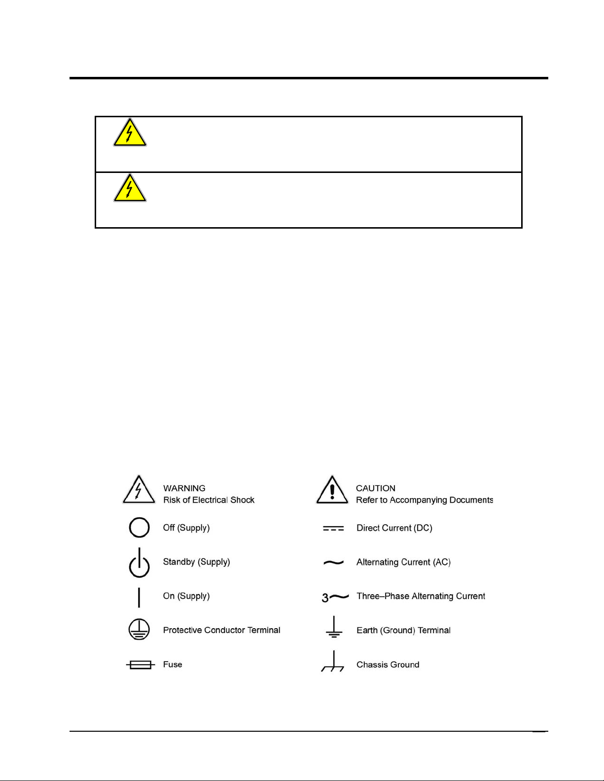
SAFETY SYMBOLS
M362000-01 Rev E
ix
Page 8

This page intentionally left blank.
x M362000-01 Rev E
Page 9

Product Family: DLM-E 3kW & 4kW Series Power Supplies
Warranty Period: Five Years
WARRANTY TERMS
AMETEK Programmable Power, Inc. (“AMETEK”), provides this written warranty covering the Product
stated above, and if the Buyer discovers and notifies AMETEK in writing of any defect in material or
workmanship within the applicable warranty period stated above, then AMETEK may, at its option: repair or
replace the Product; or issue a credit note for the defective Product; or provide the Buyer with replacement
parts for the Product.
The Buyer will, at its expense, return the defective Product or parts thereof to AMETEK in accordance with
the return procedure specified below. AMETEK will, at its expense, deliver the repaired or replaced Product
or parts to the Buyer. Any warranty of AMETEK will not apply if the Buyer is in default under the Purchase
Order Agreement or where the Product or any part thereof:
is damaged by misuse, accident, negligence or failure to maintain the same as specified or required
by AMETEK;
is damaged by modifications, alterations or attachments thereto which are not authorized by
AMETEK;
is installed or operated contrary to the instructions of AMETEK;
is opened, modified or disassembled in any way without AMETEK’s consent; or
is used in combination with items, articles or materials not authorized by AMETEK.
The Buyer may not assert any claim that the Products are not in conformity with any warranty until the
Buyer has made all payments to AMETEK provided for in the Purchase Order Agreement.
PRODUCT RETURN PROCEDURE
Request a Return Material Authorization (RMA) number from the repair facility (must be done in the
country in which it was purchased):
In the USA, contact the AMETEK Repair Department prior to the return of the product to AMETEK for
repair:
Telephone: 800-733-5427, ext. 2295 or ext. 2463 (toll free North America)
858-450-0085, ext. 2295 or ext. 2463 (direct)
Outside the United States, contact the nearest Authorized Service Center (ASC). A full listing can
be found either through your local distributor or our website, www.programmablepower.com, by
clicking Support and going to the Service Centers tab.
When requesting an RMA, have the following information ready:
Model number
Serial number
Description of the problem
NOTE: Unauthorized returns will not be accepted and will be returned at the shipper’s expense.
NOTE: A returned product found upon inspection by AMETEK, to be in specification is subject to an
evaluation fee and applicable freight charges.
M362000-01 Rev E
xi
Page 10

This page intentionally left blank.
xii M362000-01 Rev E
Page 11

ABOUT THIS MANUAL
This manual has been written expressly for AMETEK’s Sorensen brand DLM–E 3kW and 4kW series of
power supplies, which have been designed to meet the 1997 Low Voltage and Electromagnetic Compatibility
Directive Requirements of the European Community, except DLM16-185E and DLM22-180E models.
These models have been designed and tested to meet the Electromagnetic Compatibility directive
(European Council directive 2004/108/EC, generally referred to as the EMC directive) and to the
requirements of the Low Voltage directive (European Councel directive 2006/95/EC, 93/68/EEC, dated 22
July 1993). In addition, these models have been found to be compliant with FCC 47 CFR Part 15, Subpart B,
107(e) Class A, 109(g) Class A.
Since the goal of the Low Voltage Directive is to ensure the safety of the equipment operator, universal
graphic symbols (see Safety Notice above) have been used both on the unit itself and in this manual to warn
the operator of potentially hazardous situations.
M362000-01 Rev E
xiii
Page 12

This page intentionally left blank.
xiv M362000-01 Rev E
Page 13

CONTENTS
About AMETEK ............................................................................................................. vii
Important Safety Instructions .......................................................................................... ix
Warranty Terms .............................................................................................................. xi
About This Manual ........................................................................................................ xiii
SECTION 1 FEATURES AND SPECIFICATIONS ................................. 1-1
1.1 Description ....................................................................................................... 1-1
1.2 Operating Modes ............................................................................................. 1-1
1.3 Power Supply Features ................................................................................... 1-1
1.4 Specifications ................................................................................................... 1-3
1.4.1 3 kW DLM–E Electrical Specifications
1.4.2 4 kW DLM–E Electrical Specifications
1.4.3 Additional Specifications .................................................................... 1-5
1.4.4 Mechanical Specifications ................................................................. 1-6
1
............................................. 1-3
9
............................................. 1-4
SECTION 2 INSTALLATION ............................................................... 2-1
2.1 Introduction ...................................................................................................... 2-1
2.2 Safety ............................................................................................................... 2-1
2.2.1 High Energy/High Voltage Warning ................................................... 2-1
2.2.2 AC Source Grounding ....................................................................... 2-2
2.2.3 EMI Provisions ................................................................................... 2-2
2.2.4 Operating and Servicing Precautions ................................................ 2-2
2.2.5 Parts and Modifications ..................................................................... 2-3
2.3 Initial Inspection ............................................................................................... 2-3
2.3.1 Physical Check .................................................................................. 2-3
2.4 Controls, Connectors, and Indicators .............................................................. 2-3
M362000-01 Rev E xv
Page 14

Contents DLM-E 3kW & 4kW Series Power Supplies
2.4.1 Front Panel User Controls and Indicators .......................................... 2-4
2.4.2 Rear Panel ......................................................................................... 2-7
2.5 Location, Mounting, and Ventilation ................................................................. 2-8
2.5.1 Unit Dimensions ................................................................................. 2-8
2.5.2 Rack Mounting ................................................................................... 2-8
2.5.3 Ventilation .......................................................................................... 2-8
2.6 AC Input Power Connection ............................................................................. 2-9
2.6.1 AC Input Power Requirements........................................................... 2-9
2.6.2 Input Line Impedance ........................................................................ 2-9
2.7 Initial Functional Tests ................................................................................... 2-10
2.8 Load Connection ............................................................................................ 2-10
2.8.1 Load Conductor Ratings .................................................................. 2-11
2.8.2 Noise and Impedance Effects .......................................................... 2-11
2.8.3 Making the Connections .................................................................. 2-12
2.8.4 Connecting Single Loads ................................................................. 2-12
2.8.5 Connecting Multiple Loads ............................................................... 2-13
SECTION 3 BASIC OPERATION ........................................................ 3-1
3.1 Introduction ...................................................................................................... 3-1
3.2 Standard Operation .......................................................................................... 3-1
3.2.1 Operating Modes and Automatic Crossover ...................................... 3-1
3.2.2 Local Programming Mode Operation ................................................. 3-3
3.3 Using Remote Sensing .................................................................................... 3-4
3.3.1 Connecting Remote Sense Lines ...................................................... 3-4
SECTION 4 ADVANCED OPERATION ................................................ 4-1
4.1 Introduction ...................................................................................................... 4-1
4.2 Configuring for Remote Programming, Sensing, and Monitoring ....................... 4-2
4.2.1 Programming, Monitoring, and Control Functions.............................. 4-2
4.2.2 Rear Panel DIP Switch ...................................................................... 4-3
4.2.3 Resetting Rear Panel DIP Switch Settings ........................................ 4-4
4.2.4 Making J3 Connections ...................................................................... 4-4
4.3 Remote Programming of Output Voltage and Current Limit ........................... 4-5
4.3.1 Programming Output Voltage and Current Limit with the
REMOTE/LOCAL Switch ................................................................... 4-6
4.3.2 Programming Output Voltage............................................................. 4-8
xvi M362000-01 Rev El
Page 15

DLM-E 3kW & 4kW Series Power Supplies Contents
4.3.3 Programming Output Current Limit .................................................. 4-10
4.3.4 Remote Programming Only the Output Voltage or Current Limit .... 4-12
4.4 Using Over Voltage Protection (OVP) ........................................................... 4-14
4.4.1 Front Panel OVP Operation ............................................................. 4-14
4.4.2 Resetting the OVP Circuit ................................................................ 4-14
4.4.3 Programming OVP with an External Voltage Source ...................... 4-15
4.5 Using the Shutdown Function ........................................................................ 4-17
4.5.1 STANDBY Switch ............................................................................ 4-17
4.5.2 Programming the Shutdown Function ............................................. 4-17
4.5.3 Shutdown Application – Contact Closure ........................................ 4-18
4.6 Remote Monitoring ........................................................................................ 4-20
4.6.1 Readback Signals ............................................................................ 4-20
4.6.2 Status Indicators .............................................................................. 4-21
4.7 Using Multiple Supplies ................................................................................. 4-21
4.7.1 Configuring Multiple Supplies for Series Operation ......................... 4-21
4.7.2 Configuring Multiple Supplies for Split Supply Operation ................ 4-22
4.7.3 Configuring Multiple Supplies for Parallel Operation ....................... 4-24
4.8 Front Panel Lockout ....................................................................................... 4-25
4.9 Fault Alarm Signal ......................................................................................... 4-25
SECTION 5 MAINTENANCE AND TROUBLESHOOTING .................... 5-1
5.1 Periodic Service ............................................................................................... 5-1
5.2 Troubleshooting ............................................................................................... 5-1
5.2.1 Preliminary Checks ............................................................................ 5-1
5.2.2 Troubleshooting at the Operation Level ............................................ 5-2
5.3 Calibration ........................................................................................................ 5-3
5.4 Ordering Parts ................................................................................................. 5-4
5.5 Fuse Ratings .................................................................................................... 5-4
M362000-01 Rev E
xvii
Page 16

Contents DLM-E 3kW & 4kW Series Power Supplies
LIST OF TABLES
Table 4–1. J3 Connector – Program, Control, and Monitor Description ............................ 4-3
Table 4–2. Rear Panel S1 DIP Switch Functions and Settings ......................................... 4-4
Table 4–3. J12, J13 Connectors–Parallel Port Function and Pinout ............................... 4-24
Table 5–1. User Diagnostics ............................................................................................. 5-2
Table 5–2. Potentiometer Adjustment Procedures ........................................................... 5-3
Table 5–3. Fuse Ratings ................................................................................................... 5-4
xviii M362000-01 Rev El
Page 17

DLM-E 3kW & 4kW Series Power Supplies Contents
LIST OF FIGURES
Figure 2–1. EMI Suppression Filter .................................................................................. 2-2
Figure 2–2. DLM–E Controls, Connectors, and Indicators (5V–80V models) .................. 2-5
Figure 2-3. DLM–E Controls, Connectors, and Indicators (150V–600V models) ............. 2-6
Figure 2–4. Single Load with Local Sensing (Default) .....................................................2-12
Figure 2–5. Single Load with Remote Sensing ...............................................................2-13
Figure 2–6. Multiple Loads with Local Sensing ...............................................................2-14
Figure 2–7. Multiple Loads with Remote Sensing ...........................................................2-14
Figure 3–1. Operating Modes .......................................................................................... 3-2
Figure 3–2. Local Mode Default Configuration ................................................................. 3-3
Figure 3–3. J11 Sense Connector.................................................................................... 3-5
Figure 4–1. J3 Connector ................................................................................................. 4-3
Figure 4–2. Locating Jumpers, Switch, and Connector .................................................... 4-4
Figure 4–3. Programming Output Voltage, Current Limit and OVP with REM/LOC Switch4-7
Figure 4–4. Programming Output Voltage with a 0–5 VDC or 0–10 VDC Source ............ 4-8
Figure 4–5. Programming Output Voltage with a 0–5k Ohm Resistance ......................... 4-9
Figure 4–6. Programming Output Current Limit with a 0–5 VDC or 0–10 VDC Source ...4-10
Figure 4–7. Programming Output Current Limit with a 0–5k Ohm Resistance ................4-11
Figure 4–8. Programming Output Voltage Remotely, Local Control of Current Limit/OVP4-12
Figure 4–9. Programming Output Current Remotely, Local Control of Voltage Limit/OVP4-13
Figure 4–10. Remote Programming of OVP with a 0–5 VDC or 0–10 VDC External Voltage
Source .......................................................................................................4-15
Figure 4–11. Remote Programming of OVP with a 0–5k ohm Resistance ......................4-16
Figure 4–12. Using Shutdown with a DC Input (Positive Logic) ......................................4-18
Figure 4–13. Using Shutdown with Contact Closure of a Normally OPEN Relay (S1-6 Up)4-
19
Figure 4–14. Using Shutdown with Contact Closure of a Normally OPEN Relay (S1-6 Down)
..................................................................................................................4-19
Figure 4–15. Using Shutdown with Contact Closure of a Normally CLOSED Relay (S1-6 Up)
..................................................................................................................4-19
Figure 4–16. Using Shutdown with Contact Closure of Normally CLOSED Relay (S1-6
Down) ........................................................................................................4-20
Figure 4–17. Series Operation of Multiple Supplies ........................................................4-22
Figure 4–18. Split Supply Operation of Multiple Supplies (Two Positive Voltages) .........4-23
Figure 4–19. Split Supply Operation of Multiple Supplies (Positive–Negative Supply) ....4-23
Figure 4–20. Parallel Operation of Multiple Supplies ......................................................4-25
Figure 5–1. Potentiometer Locations ............................................................................... 5-3
M362000-01 Rev E
xix
Page 18

Page 19

SECTION 1
FEATURES AND
SPECIFICATIONS
1.1 Description
The DLM–E Series 3000 and 4000 watt power supplies are designed to provide highly stable,
continuously variable output voltage and current for a broad range of development, system and
burn–in applications. Model numbers for this series are designated by the DLM prefix, followed
by the output voltage and current ratings. For example, the model number DLM40–100E
indicates that the unit is rated at 0–40 VDC and 0–100 amps while a model DLM8–350E is rated
at 0–8 VDC and 0–350 amps. The DLM–E Series employs high frequency switching regulator
technology to achieve high power density and small package size.
1.2 Operating Modes
The DLM–E Series supply has two basic operating modes: Constant Voltage and Constant
Current. In constant voltage mode, the output voltage is regulated at the selected value while
the output current varies with the load requirements. In constant current mode, the output
current is regulated at the selected value while output the voltage varies with the load
requirements.
An automatic crossover system enables the unit to switch operating modes in response to
varying load requirements. If, for example, the unit is operating in voltage mode and the load
current attempts to increase above the setting of the current control, the unit will switch
automatically from voltage mode to current mode. If the load current is subsequently reduced
below the setting of the current control the unit will return to voltage mode automatically.
1.3 Power Supply Features
• 3 kW and 4 kW models with voltage ranges from 0–5 VDC to 0–600 VDC and
current ranges from 0–5A to 0–450A.
• 3 kW models operate with either single or three–phase AC input power without
jumpers.
• High input AC power factor, 0.95 typical, with three–phase 208, 400, or 480 VAC
inputs.
M362000-01 Rev E 1-1
Page 20

Features and Specifications DLM-E 3kW & 4kW Series Power Supplies
• High input AC power factor, 0.98 typical, with single–phase input.
• Front panel controls for Enable/Standby and Local/Remote modes of operation.
• Simultaneous digital display of both DC voltage and current.
• Front panel preview switch allows voltage, current, and OVP to be preset from local
or remote control.
• Local lockout feature with front panel indicator is selectable by rear panel switch.
• No internal jumpers or switches to change programming and monitor ranges.
• Current sharing parallel port and simple cable interface allows several units to be
connected in parallel to provide increased power and current.
• Voltage and current controls with ten turn potentiometers permit high resolution
setting of the output voltage and current from zero to the rated output.
• Automatic mode crossover into current or voltage mode, with mode indication.
• High frequency switching technology allows high power density, providing
increased power output in a small package.
• Remote sensing to compensate for losses in power leads.
• Fast response time for programming or load changes.
• Adjustable Over–Voltage Protection (OVP) with preview
• External DC shutdown (positive or negative logic selectable).
• Remote voltage, current, and OVP programming with selectable programming
range.
• External indicator signals for remote monitoring of OVP status, local/remote
programming status, thermal shutdown, and output voltage and current.
• Installation Category III, Pollution degree 2.
For Indoor Use Only.
• CE Approvals to EN61010-1 1993
CE Mark tested to: EN61326
EN61010-1:1993
(FCC) 47 CFR Part 15, Subpart B, 107 (e), Class A, 109 (g) Class A
• Optional IEEE-488 interface for complete remote programming and readback
capability with M9E option.
• M85 slave option allows programming of up to 31 power supplies from one GPIB
address.
1-2 M362000-01 Rev E
Page 21

DLM-E 3kW & 4kW Series Power Supplies Features and Specifications
1.4 Specifications
1.4.1 3 kW DLM–E Electrical Specifications1
Model 5–350 8–350 16–185 32–95 40–75 60–50 80–37 150–20 300–10 600–5
Output Ratings:
Output Voltage
Output Current
Output Power
Line Regulation:2
Voltage (0.05% of Vmax+2mV)
Current (0.1% of Imax)
Load Regulation:3
Voltage (0.05% of Vmax+2mV)
Current (0.1% of Imax)
Meter Accuracy:
Voltage (0.5% Vmax+1count)
Current (1.0% Imax+1count)
Preview Accuracy
Voltage (0.5% Vmax+1 count)
Current (1.0% Imax+1 count)
OVP Adjustment Range
(6% to 110% Vmax)
Output Noise and Ripple (V)
RMS
p–p (20 Hz–20 MHz)
5, 6
Stability:
Voltage (0.05% of Vmax)
Current (0.05% of Imax)
0–5V
0–350A
1750W
5 mV
350 mA
5 mV
350 mA
0.04V
4A
0.04V
6A
0–8V
0–350A
2800W
6 mV
350 mA
6 mV
350 mA
0.05V
4A
0.05V
5A
0.3–5.5V 0.4–8.8V
12 mV
100 mV
3 mV
175 mA
12 mV
4
100 mV
4 mV
175 mA
0–16V
0–185A
2960W
10 mV
185 mA
10 mV
185 mA
0.09V
3A
0.09V
3A
0.8–
17.6V
10 mV
4
100 mV
8 mV
93 mA
0–32V
0–95A
3040W
18 mV
95 mA
18 mV
95 mA
0.3V
0.8A
0.3V
1.1A
1.6–35V
10 mV
4
100 mV
16 mV
48 mA
0–40V
0–75A
3000W
22 mV
75 mA
22 mV
75 mA
0.3V
0.7A
0.3V
0.9A
0–60V
0–50A
3000W
32 mV
50 mA
32mV
50 mA
0.4V
0.5A
0.4V
0.6A
0–80V
0–37A
2960W
42 mV
37 mA
42 mV
37 mA
0.5V
0.4A
0.5V
0.5A
2–44V 3–66V 4–88V
10 mV
4
100 mV
20 mV
38 mA
15 mV
4
100 mV
30 mV
25 mA
15 mV
120 mV
40 mV
19 mA
0–150V
0–20A
3000W
77 mV
20 mA
77 mV
20 mA
0.9V
0.3A
0.9V
0.3A
7.5–
165V
30 mV
200 mV
75 mV
10 mA
0–300V
0–10A
3000W
152 mV
10 mA
152 mV
10 mA
3V
0.09A
3V
0.11A
0–600V
0–5A
3000W
302 mV
5 mA
302 mV
5 mA
4V
0.05A
4V
0.06A
15–330V 30–660V
60 mV
300 mV
150 mV
5 mA
100 mV
500 mV
300 mV
2.5 mA
Temperature Coefficient:7
Voltage (0.02% of Vmax)
Current (0.03% of Imax)
Maximum Remote Sense
Line Drop Compensation per line
1. Specifications are warranted over a temperature range of 0–50°C with default local sensing.
From 50–70°C, derate output 2% per °C.
From 40–70°C, derate output 2% per °C below 190 VAC with single or three–phase inputs.
2. For input voltage variation over the AC input voltage range, with constant rated load.
3. For 0–100% load variation, with constant nominal line voltage.
4. Typical P–P noise and ripple is 50 mV.
5. Maximum drift over 8 hours with constant line, load, and temperature, after 15 minute warm–up (30 minute warm–up
for 5V, 8V, and 16V models).
6. Current accuracy for 5V, 8V, and 16V models is 1% typical.
7.
Change in output per °C change in ambient temperature, with constant line and load.
8. Line drop subtracts from the maximum available output voltage at full rated power.
1 mV
105 mA
2V 2V 2V 5V 5V 5V 5V 5V 5V 5V
8
1.6 mV
105 mA
3.2 mV
55 mA
6 mV
30 mA
8 mV
23 mA
12 mV
15 mA
16 mV
12 mA
30 mV
6 mA
60 mV
3 mA
120 mV
1.5 mA
M362000-01 Rev E
1-3
Page 22

Features and Specifications DLM-E 3kW & 4kW Series Power Supplies
1.4.2 4 kW DLM–E Electrical Specifications9
Model 5–450 8–450 16–250 22-180 32–125 40–100 60–66 80–50 150–26 300–13 600–6.6
Output Ratings:
Output Voltage
Output Current
Output Power
Line Regulation:10
Voltage (0.05% of Vmax+2mV)
Current (0.1% of Imax)
Load Regulation:11
Voltage (0.05% of Vmax+2mV)
Current (0.1% of Imax)
Meter Accuracy:
Voltage (0.5% Vmax+1count)
Current (0.75% Imax+1count)
Preview Accuracy
Voltage (0.5% Vmax+1 count)
Current (1.0% Imax+1 count)
OVP Adjustment Range
(6% to 110% Vmax)
Output Noise and Ripple (V)
RMS
p–p (20 Hz–20 MHz)
13, 14
Stability:
Voltage (0.05% of Vmax)
Current (0.05% of Imax)
0–5V
0–450A
2250W
5 mV
450 mA
5 mV
450 mA
0.04V
5A
0.04V
6A
0.3–
5.5V
12 mV
100
12
mV
3 mV
225 mA
0–8V
0–450A
3600W
6 mV
450 mA
6 mV
450 mA
0.05V
5A
0.05V
6A
0.4–
8.8V
12 mV
100
mV12
4 mV
225 mA
0–16V
0–250A
4000W
10 mV
250 mA
10 mV
250 mA
0.09V
3A
0.09V
4A
0.8–
17.6V
10 mV
100
mV12
8 mV
125 mA
0-22V
0-180A
4000W
13 mV
180mA
13 mV
180mA
0.2V
3A
0.2V
3A
1.1-
24.2V
10 mV
100
mV12
11 mV
90 mA
0–32V
0–125A
4000W
18 mV
125 mA
18 mV
125 mA
0.3V
1A
0.3V
1.4A
1.6–35V
10 mV
100
mV12
16 mV
63 mA
0–40V
0–100A
4000W
22 mV
100 mA
22 mV
100 mA
0.3V
0.9A
0.3V
1.1A
0–60V
0–66A
3960W
32 mV
66 mA
32mV
66 mA
0.4V
0.6A
0.4V
0.8A
0–80V
0–50A
4000W
42 mV
50 mA
42 mV
50 mA
0.5V
0.5A
0.5V
0.6A
2–44V 3–66V 4–88V
10 mV
100
mV12
20 mV
50 mA
15 mV
100 mV
30 mV
33 mA
15 mV
120 mV
40 mV
25 mA
0–150V
0–26A
3900W
77 mV
26 mA
77 mV
26 mA
0.9V
0.3A
0.9V
0.4A
7.5–
165V
30 mV
100 mV
75 mV
13 mA
0–300V
0–13A
3900W
152 mV
13 mA
152 mV
13 mA
1.6V
0.11A
3V
0.14A
15–
330V
60 mV
150 mV
150 mV
6.5 mA
0–600V
0–6.6A
3960W
302 mV
7 mA
302 mV
7 mA
3.1V
0.06A
4V
0.08A
30–
660V
100 mV
300 mV
300 mV
3.3 mA
Temperature Coefficient:15
Voltage (0.02% of Vmax)
Current (0.03% of Imax)
Maximum Remote Sense
Line Drop Compensation per line
9. Specifications are warranted over a temperature range of 0–50°C with default local sensing.
From 50–70°C, derate output 2% per °C.
From 40–70°C, derate output 2% per °C below 190 VAC with single or three–phase inputs.
10. For input voltage variation over the AC input voltage range, with constant rated load.
11. For 0–100% load variation, with constant nominal line voltage.
12. Typical P–P noise and ripple is 50 mV.
13. Maximum drift over 8 hours with constant line, load, and temperature, after 15 minute warm–up (30 minute warm–up
for 5V, 8V, and 16V models).
14. Current accuracy for 5V, 8V, and 16V models is 1% typical.
15.
Change in output per °C change in ambient temperature, with constant line and load.
16. Line drop subtracts from the maximum available output voltage at full rated power.
1 mV
135 mA
2V 2V 2V 2V 5V 5V 5V 5V 5V 5V 5V
16
1.6 mV
135 mA
3.2 mV
75 mA
4.4 mV
54 mA
6 mV
38 mA
8 mV
30 mA
12 mV
19.8 mA
16 mV
15 mA
30 mV
7.8 mA
60 mV
3.9 mA
120 mV
2.0 mA
1-4 M362000-01 Rev E
Page 23
DLM-E 3kW & 4kW Series Power Supplies Features and Specifications
1.4.3 Additional Specifications
AC Input:
Output
Power
3 kW19
3 kW19
4 kW
4 kW
4 kW
17. Maximum input current measured at low AC line and maximum output power.
18. Power factor measured at nominal line, maximum output power.
19.
The 3 kW DLM–E is designed to operate without derating to the output power level with either
a single–phase or three–phase AC input voltage without any internal jumper changes.
Nominal Input
Voltage
230 VAC
Single–Phase
208 VAC
Three–Phase
208 VAC
Three–Phase
380/400/415 VAC
Three–Phase
480 VAC
Three–Phase
Input
Option
Std 180–264 VAC L–L 21A RMS 0.98
Std 180–264 VAC L–L 12A RMS 0.95
Std 180–264 VAC L–L 15A RMS 0.95
M1 345–455 VAC L–L 8.5A RMS 0.95
M2 432–528 VAC L–L 6.5A RMS 0.95
Input Range
(47–63 Hz)
Input Current
Maximum
17
Input Power
Efficiency: 5 and 8 VDC models – 82% typical, 16–600 VDC models – 87% typical
Altitude: 2000M (6562 Ft.)
Operating Temperature Range: 0 to 50°C
Storage Temperature Range: –40 to +85°C
Factor18
Humidity Range: 0 to 80% Non–condensing
Time Delay from power on until output is stable: 10 seconds maximum
Voltage Mode Transient Response Time: 1 ms recovery to 1% band for 30% step load
change from 70% to 100% or 100% to 70%
Remote Start/Stop and Interlock: TTL compatible input, Contact Closure, 5–24 VDC.
Switching Frequency: Nominal 32 kHz (64 kHz output ripple)
Float Voltage: Negative output terminal may be biased to 150 VDC relative to chassis.
For models 16V, 22V output terminal may be biased to 600 VDC relative to
chassis.
Remote Analog Programming (Full Scale Input): Scales are selectable through rear panel.
Parameter Resistance Voltage
Voltage
Current
OVP
5 kΩ
5 kΩ
5 kΩ
5V, 10V
5V, 10V
5V, 10V
Analog Programming Accuracy: 1% of rated output for voltage programming, 5% of rated
output for resistance programming, 2% of rated output voltage for OVP.
M362000-01 Rev E
1-5
Page 24

Features and Specifications DLM-E 3kW & 4kW Series Power Supplies
1.4.4 Mechanical Specifications
Unit Dimensions
Height Width Depth Weight
87.6 mm (3.5 in) 482.6 mm (19 in) 508 mm (20 in) 18.2 kg (40 lbs.)
Output Connector (Models DLM5–XXX through DLM80–XX)
Connector type: Nickel–plated copper bus bars
Approximate dimensions: 1" wide x 0.25" thick
Distance between positive and negative bus bar main mount in holes: 2.5"
Load wiring mounting holes: Two 0.312" diameter holes for securing high current output
cables. Four 0.201" diameter holes for securing lower current cables and sense leads.
Remote Sensing: Two pin screw–clamp removable mating connector housing is supplied with
each unit for remote sensing. Accommodates sense lead wire 16–22 AWG.
Output Connector (Models DLM150–XX through DLM600–XX)
Connector type: Four–position terminal block (two positive and two negative connections)
#6–32 plated Phillips head SEMS screws accommodate up to #12 AWG.
Approximate dimensions: Terminal center spacing of 0.437"
Safety: Three-sided plastic cover provided with wire exit cutouts.
Remote Sensing: Two pin screw–clamp removable mating connector housing is supplied with
each unit for remote sensing. Accommodates sense lead wire 16–22 AWG.
Input Connector
AC Input: 3–position fuse block with screw clamp connectors.
Ground: 10–32 safety ground stud on chassis located below fuse block.
Note 1: Screw clamp connectors accommodate up to AWG #6.
Note 2: Power cables not supplied.
Note 3: A clamp–on EMI filter is supplied with each power supply to allow compliance with the
Electromagnetic Compatibility Directive requirements of the European Community.
See Section 2 for proper installation.
SPECIFICATIONS SUBJECT TO CHANGE WITHOUT NOTICE
1-6 M362000-01 Rev E
Page 25

SECTION 2
INSTALLATION
2.1 Introduction
This section provides recommendations and procedures for inspecting, testing, and installing
the DLM–E Series power supply.
1. Read and follow safety recommendations (Section 2.2)
2. Perform an initial physical inspection of the supply (Section 2.3)
3. Become familiar with Controls, Indicators and Rear Panel layout (Section 2.4)
4. Install the supply, ensuring adequate ventilation (Section 2.5)
5. Connect the AC input power (Section 2.6)
6. Perform initial function tests for voltage mode operation, current mode operation, and
front panel controls (Section 2.7)
7. Connect the load (Section 2.8)
Instructions for Local Programming Mode operation (Constant Voltage and Constant Current)
are given in Section 3 Basic Operation. Remote Programming operation, monitoring, and
programmable functions are described in Section 4 Advanced Operation.
2.2 Safety
Please review the following points for both personal and equipment safety while using the
DLM–E Series power supplies.
2.2.1 High Energy/High Voltage Warning
Exercise caution when using and servicing power supplies. High energy levels can be stored at
the output voltage terminals on all power supplies in normal operation. In addition, potentially
lethal voltages exist in the power circuit and the output connector of power supplies that are
M362000-01 Rev E 2-1
Page 26

Installation DLM-E 3kW & 4kW Series Power Supplies
rated at 40V and over. Filter capacitors store potentially dangerous energy for some time after
power is removed.
Use extreme caution when biasing the output relative to the chassis due to potentially high
voltage levels at the output terminals. The output of the DLM–E Series supplies may be biased
up to a maximum voltage relative to the chassis as specified in Section 1 under Additional
Specifications.
2.2.2 AC Source Grounding
Ensure the power supply is connected to an appropriately rated AC outlet with the
recommended AC input wiring as set out in Section 2.6 AC Input Power Connection. There is a
potential shock hazard if the power supply chassis and cover are not connected to a power
return via the safety ground on the chassis. The third wire in a single phase AC input connector
and the fourth wire in a three phase AC input connector must be connected to an electrical
ground at the power outlet. Any disconnection of this ground will cause a potential shock hazard
to operating personnel.
This power supply is equipped with an AC line filter to reduce electromagnetic interference and
must be connected to a properly grounded receptacle, or a shock hazard will exist.
2.2.3 EMI Provisions
A clamp–on EMI suppression filter core is included with each unit to allow compliance with the
Electromagnetic Compatibility Directive requirement of the European Community. This filter is to
be installed so that all of the AC input wires and
input fuse block and chassis are clamped inside the filter before operating. See Figure 2–1.
Figure 2–1. EMI Suppression Filter
ground wire that connect to the unit at the AC
2.2.4 Operating and Servicing Precautions
Exceeding a model's maximum rated input voltage may cause permanent damage to the unit.
The power supply must not be operated where flammable gases or fumes exist.
2-2 M362000-01 Rev E
Page 27

DLM-E 3kW & 4kW Series Power Supplies Installation
Always disconnect power, remove external voltage sources, and allow time for internal circuits
to discharge before making internal adjustments or replacing components. When performing
internal adjustments or servicing the unit, ensure another person with first aid and resuscitation
certification is present. Repairs must be made by experienced technical personnel only.
Be sure to isolate the power supply from the input line with an isolation transformer when using
grounded test equipment, such as an oscilloscope, in the power circuit as these are referenced
to the AC input line.
WARNING!
Removal of the front panel filter and cover allows access to moving parts
and potentially hazardous voltages. Ensure that the power is turned off
prior to removal of the filter for maintenance or cleaning.
2.2.5 Parts and Modifications
Do not use substitute parts or make any unauthorized modifications to the power supply to
ensure that its safety features are not degraded. Contact customer service engineers for service
and repair help.
2.3 Initial Inspection
Upon first receiving your DLM–E Series power supply, perform a quick physical check, paying
particular attention to front panel controls and indicators as well as rear panel connectors and
terminals. The front and rear panel diagrams are located in Section 2.4.
2.3.1 Physical Check
After unpacking, perform an initial inspection to ensure the unit and parts shipped with it have
not been damaged in transit. The package should contain the power supply, a manual, a remote
sense connector, a 25–pin sub–D mating connector for J3, and an EMI filter core.
1. Inspect for dents to the cover and chassis; for scratches and cracks on the front and rear
panels; and for any broken controls, connectors, or displays.
2. Turn front panel controls from stop to stop. Rotation should be smooth.
3. Test the action of the POWER switch. Switching action should be positive.
4. If internal damage is suspected, remove the cover and check for printed circuit board
and/or component damage. Reinstall cover.
If damage has occurred, save all packing materials and notify the carrier immediately. Refer to
the terms of the warranty. Direct any repair problems to the manufacturer.
Note: Section 2.7 Initial Functional Tests contains electrical and operational tests you can
perform to ensure the unit is in proper working order after shipment. Run these tests
after applying AC input power but before connecting the load to the power supply.
2.4 Controls, Connectors, and Indicators
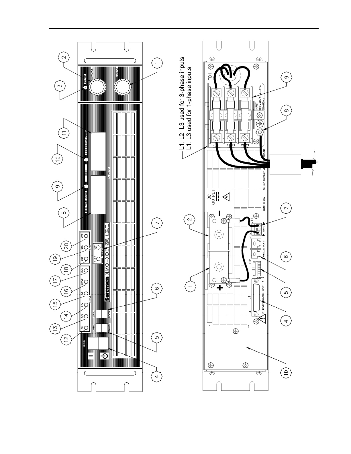
Refer to Figure 2–2 or Figure 2-3 (depending on the model) and the descriptions below.
M362000-01 Rev E
2-3
Page 28

Installation DLM-E 3kW & 4kW Series Power Supplies
2.4.1 Front Panel User Controls and Indicators
1. CURRENT knob: 10 turn adjustment sets the output current.
2. VOLTAGE knob: 10 turn adjustment sets the output voltage.
3. OVP SET potentiometer: 20 turn trim pot recessed behind front panel sets the over
voltage trip limit.
4. POWER switch: Two–position switch enables or disables the supply.
5. ENABLE/STANDBY switch: Two–position switch allows the unit to be placed in an
active (enabled) or inactive (standby) mode. The front panel displays are still active in
the STANDBY mode.
6. LOCAL/REMOTE switch: Two–position switch selects if the front panel VOLTAGE,
CURRENT and OVP controls (local) or the analog programming inputs from the rear
panel J3 connector (remote) will determine the output settings for the supply.
7. PREVIEW switches: Two momentary push button switches. While in the STANDBY
mode, the V&I button will display the output voltage and current settings prior to power
being applied to the load. The OVP button will display the over voltage shutdown set
point. Local or remote signal preview settings are selectable with the LOCAL/REMOTE
mode switch position.
8. VOLTAGE DISPLAY: 3½ digit green LED display normally indicates DC output voltage
of supply. Indicates preset output voltage setting when the V&I PREVIEW button is
pushed and indicates the OVP setting when the OVP PREVIEW button is pushed.
9. VOLTAGE MODE indicator: Green LED lights when in the constant–voltage mode of
operation. When in the constant voltage mode, the output voltage will regulate to the set
value and the current value will vary with the load.
10. CURRENT MODE indicator: Green LED lights when in the constant–current mode of
operation. When in the constant current mode, the output current will regulate to the set
value and the output voltage will vary with the load.
11. CURRENT DISPLAY: 3½ digit green LED display normally indicates DC output current
of supply. Push the V&I PREVIEW button to display preset output current setting.
12. ON (AC Input Power ON) indicator: Yellow LED lights when power switch is on and AC
is applied. (Note: this LED does NOT indicate DC output status.)
13. S/D (Shutdown) indicator: Red LED lights when the unit has been shutdown remotely.
14. REM (Remote) indicator: Green LED lights when unit is in remote programming mode.
15. OVP (Over Voltage Protection) indicator: Red LED lights when an over voltage
shutdown has occurred.
2-4 M362000-01 Rev E
Page 29
DLM-E 3kW & 4kW Series Power Supplies Installation
Figure 2–2. DLM–E Controls, Connectors, and Indicators (5V–80V models)
M362000-01 Rev E
2-5
Page 30

Installation DLM-E 3kW & 4kW Series Power Supplies
Figure 2-3. DLM–E Controls, Connectors, and Indicators (150V–600V models)
2-6 M362000-01 Rev E
Page 31

DLM-E 3kW & 4kW Series Power Supplies Installation
16. OTEMP (Over Temperature) indicator: Red LED lights when an over temperature
shutdown has occurred.
17. LOCK (Lockout) indicator: Green LED lights when in Lockout mode. Activated by
connection through rear panel DIP switch. Can only be activated when the front panel
LOCAL/REMOTE switch is in the REMOTE position. Once the Lock function has been
activated, it disables LOCAL control for all output control functions except the AC power
switch, which remains under front panel control.
The following indicators will be illuminated only when the optional GPIB controller is installed:
18. ERR (Error) indicator: Red LED lights to signal a GPIB programming error has occurred.
19. SRQ (Service Request) indicator: Green LED lights to signal GPIB service request by
the supply.
20. ADDR (Address) indicator: Green LED lights when the unit is addressed by a remote
controller.
2.4.2 Rear Panel
Refer to Figure 2–2 or Figure 2-3 (depending on the model) and the descriptions below.
1. Positive Output (+). Bus bar for 5V through 80V models.
TB2–1 and 2 for 150V through 600V models.
2. Negative Output (–). Bus bar for 5V through 80V models.
TB2–3 and 4 for 150V through 600V models.
3. Output connector location for 150V through 600V models.
4. Programming and Monitor Connector, J3. I/O connector for input programming and
analog output monitoring signals as well as status indication and remote shutdown
signals. See Table 4–1 for individual pin descriptions.
5. DIP Switch S1. Eight–position right angle slide DIP switch. Controls full scale settings for
Voltage, Current and OVP programming range, Voltage and Current Output Monitor
range, Remote On–Off logic selection, Master/Slave operation and Lockout operating
mode selections. See Table 4–2 for Rear Panel DIP switch functions and settings.
6. Parallel Port connectors, J12 and J13. Used in conjunction with S1 setting to control
multiple units in parallel mode with current sharing. See Table 4–2 for Rear Panel DIP
switch functions and settings and Table 4–3 for parallel port connector function and
pinout.
7. Sense connector, J11. Remote sense lead connection for local and remote load voltage
sensing on all models. Connections shown are for local sensing on all models.
8. AC Input chassis safety ground stud.
9. AC Input Connector/fuse block with removable safety cover.
10. Area for optional GPIB assembly.
M362000-01 Rev E
2-7
Page 32

Installation DLM-E 3kW & 4kW Series Power Supplies
2.5 Location, Mounting, and Ventilation
The DLM–E system supply is designed for use in rack mounted applications. Ensure that
sufficient space is allowed for cooling air to reach the ventilation inlets on the front of the unit,
and for fan exhaust air to exit from the rear of the unit.
2.5.1 Unit Dimensions
Dimension Height Width Depth Weight
Standard 3.5 in 19 in 20 in 40 lbs
Metric 87.6 mm 482.6 mm 508 mm 18.2 kg
2.5.2 Rack Mounting
The supply is designed to fit in a standard 19" equipment rack. Use adjustable support angles
such as Hammond RASA22WH2, or a support bar such as Hammond RASB19WH2. Bolt holes
in the chassis sides are provided for rack mount slides such as the ZERO #C300S18 slides.
Be sure to provide adequate support for the rear of the unit while not obstructing the exhaust
outlets at the rear of the unit.
CAUTION!
Rack mounting bolts must not extend more than
power supply.
3/16" into the side of the
2.5.3 Ventilation
The DLM–E system supply is fan–cooled, so it requires unobstructed space on the front
ventilation inlets and space at the rear for the ventilation exhaust. The following temperature
ranges apply for the best results when operating or storing the unit.
Operating Ambient Temperature
0 to 50° C with no derating. –40 to +85° C
1. From 50 to 70° C, derate 2% per °C.
From 40 to 70°C, derate 2% per °C below 190 VAC with single or three–phase inputs.
1
Storage Temperature Range
2-8 M362000-01 Rev E
Page 33

DLM-E 3kW & 4kW Series Power Supplies Installation
2.6 AC Input Power Connection
Before you can use the DLM–E system supply, you must determine your AC input power
requirements and connect an appropriate cable or line cord to the input connector. The power
supply is shipped with an input connector cover which you need to remove to make the input
power connections.
WARNING!
A device to disconnect the DLM–E supply from the energy supply source is
required. This switch or circuit breaker must be close to the DLM–E supply,
within easy reach of the operator, and clearly labeled as the disconnection
device for the DLM–E supply.
2.6.1 AC Input Power Requirements
The specifications for input voltage, current, and frequency are listed below.
Output
Power
3 kW3
3 kW3
4 kW
4 kW
4 kW
2. Maximum input current measured at low AC line and maximum output power.
3. The 3 kW DLM–E is designed to operate without derating to the output power level with either
a single–phase or three–phase AC input voltage without any internal jumper changes.
4. Single-phase AC inputs use L1 and L3 only. Improper connections will result in no output.
Nominal Input
Voltage
230 VAC
Single–Phase
208 VAC
Three–Phase
208 VAC
Three–Phase
380/400/415 VAC
Three–Phase
480 VAC
Three–Phase
Input
Option
Input Range
(47–63 Hz)
Input Current
Maximum
Std 180–264 VAC L–L 20A RMS
Std 180–264 VAC L–L 12A RMS
Std 180–264 VAC L–L 15A RMS
M1 345–455 VAC L–L 8.5A RMS
M2 432–528 VAC L–L 6.5A RMS
2
AC Input
Terminals
L1–L2–L3
(F1–F2–F3)
L1–L2–L3
(F1–F2–F3)
L1–L2–L3
(F1–F2–F3)
L1–L2–L3
(F1–F2–F3)
L1–L3
4
(F1–F3)
2.6.2 Input Line Impedance
The maximum input line impedance for operation at full rated output is 0.1 ohm. Higher source
impedance can be tolerated by raising the input line voltage or by reducing the power.
M362000-01 Rev E
2-9
Page 34

Installation DLM-E 3kW & 4kW Series Power Supplies
2.7 Initial Functional Tests
Before connecting the unit to an AC outlet, make sure that the POWER switch is in the Off
position, (down) and that the voltage and current control knobs are turned fully counter–
clockwise. The two smaller switches directly to the right of the POWER switch should be
depressed up to put the unit in the ENABLE and LOCAL position. Check that the J3 mating
connector on the rear of the unit has no jumpers installed on it and that the rear panel DIP
switch, S1, settings are all in the UP (1) position. (This is the default configuration as shipped
from the factory). Connect the unit to the proper AC power source and turn the POWER switch
on. After a 1–2 second power–on delay, the front panel meters should light up with both
displays reading zero. The S/D (shutdown) indicator will blink momentarily and then the ON and
VOLT MODE indicators should be illuminated.
To check voltage mode operation, proceed as follows:
• Connect a DVM, rated better than 0.5% accuracy, to the rear output terminals, observing
correct polarity.
• Rotate the CURRENT control ½ turn clockwise. Slowly rotate the VOLTAGE control
clockwise and observe both the internal and external meters. The control range should
be from zero to the maximum rated output. Compare the test meter reading with the front
panel voltmeter reading. Check that the green VOLTAGE MODE indicator is ON.
• Set the POWER switch to OFF. Note that the internal fans will continue to run for about
10 seconds.
To check current mode operation, proceed as follows:
• Rotate the VOLTAGE and CURRENT controls fully counterclockwise.
• Rotate the VOLTAGE control ½ turn clockwise.
• Connect a high current DC ammeter or current shunt across the rear output terminals,
observing correct polarity. Select cables of sufficient current carrying capacity and an
ammeter range compatible with the unit's rated current output. The ammeter/shunt
should have an accuracy of better than 0.5%.
• Set the POWER switch to ON.
• Rotate the CURRENT control slowly clockwise. The control range should be from zero to
the maximum rated output. Compare the test meter reading with the reading on the front
panel ammeter. Check that the green CURRENT MODE indicator is ON.
• Set the POWER switch to OFF. Note that the internal fans will continue to run for about
10 seconds.
2.8 Load Connection
Reliable performance of the DLM–E power supply can be obtained if certain basic precautions
are taken when connecting it in a system. To obtain a stable, low noise output, careful attention
should be paid to factors such as conductor ratings, system grounding techniques and the way
in which the load and remote sensing connections are made.
2-10 M362000-01 Rev E
Page 35

DLM-E 3kW & 4kW Series Power Supplies Installation
2.8.1 Load Conductor Ratings
As a minimum, load wiring must have a current capacity greater than the output current rating of
the power supply. This ensures that the wiring will not be damaged even if the load is shorted.
The table below shows the maximum current rating, based on 450 amps per square centimeter,
for various gauges of wire rated for 105 degrees C operation.
Operation at the maximum current rating results in approximately a 30–degree temperature rise
for a wire operating in free air. Where load wiring must operate in areas with elevated ambient
temperatures or bundled with other wiring, larger gauges or higher temperature–rated wiring
should be used.
To overcome impedance and coupling effects, which can degrade the power supply
performance, the use of leads of the largest gauge and shortest length possible is
recommended.
AWG Maximum Current AWG Maximum Current
16 7 1 209
14 11 1/0 270
12 18 2/0 330
10 23 3/0 350
8 39 4/0 408
6 67 250 MCM 425
4 106 300 MCM 480
2 170
2.8.2 Noise and Impedance Effects
To minimize noise pickup or radiation from load circuits, load wires and remote sense wires
should be twisted-pair with minimum lead length. Shielding of the sense leads may be
necessary in high noise environments. Even if noise is not a concern, the load and remote
sense wires should be twisted-pairs to reduce coupling between them, which could impact the
stability of the power supply. If connectors are utilized for the power and sense leads, be
careful not to introduce coupling between the leads. Ensure that the connector terminals for the
sense leads are in adjacent locations, and minimize the physical loop area of the untwisted
portions. Ideally, the sense leads should be separated from the power leads and should have
their own connector.
Twisting the load wires provides an additional benefit in reducing the parasitic inductance of the
cable. This improves the dynamic response characteristics at the load by maintaining a low
source impedance at high frequencies. Also, with long load wires, the resultant inductance and
resistance could produce high frequency voltage spikes at the load due to current variations in
the load itself. The impedance introduced between the output of the power supply and the load
could make the ripple/noise at the load worse than the specifications of the power supply (which
are valid when measured at the rear panel bus bars). Additional filtering with bypass capacitors
at the load terminals may be required to bypass the high frequency load currents.
M362000-01 Rev E
2-11
Page 36

Installation DLM-E 3kW & 4kW Series Power Supplies
2.8.3 Making the Connections
Load connections to the power supply are made at the positive and negative output terminals
(or bus bars) at the rear of the power supply. See Figure 2–2. The power supply provides three
load wiring mounting holes on each bus bar terminal, as specified in the following table. The
small holes can be used for local sense lines.
Load Wiring Mounting Holes Diameter Hardware Size
One (1) per terminal 0.312" 1/4" (5/16" for 8V and 16V models)
One (1) per terminal #6–32 Screw 0.32" OD (for 150V–600V models)
Two (2) per terminal 0.201" on 0.5" centers #10 or smaller
CAUTION!
When making connections to the bus bars, provide support when tightening
hardware to prevent bending bus bars. Ensure that the mounting hardware at
each terminal and wiring assembly is placed to avoid touching the other
terminal and shorting the power supply output. Heavy connecting cables
must have some form of strain relief to avoid loosening the connections or
bending the bus bars.
CAUTION!
If unit is not installed in a rack, care should be taken to protect personnel
from contact with output bus bars.
2.8.4 Connecting Single Loads
Figure 2–4 and Figure 2–5 show recommended load and sensing connections for a single load.
Local sense lines shown are default J11 connections. Refer to Section 3.3.1 Connecting
Remote Sense Lines for more information about the sense line shield.
Figure 2–4. Single Load with Local Sensing (Default)
(Local sense lines shown are default J11 to busbar connections)
2-12 M362000-01 Rev E
Page 37

DLM-E 3kW & 4kW Series Power Supplies Installation
Figure 2–5. Single Load with Remote Sensing
(Local sense lines shown are default J11 to busbar connections)
2.8.5 Connecting Multiple Loads
Proper connection of distributed loads is an important aspect of power supply applications.
Two common methods of connection are the parallel power distribution method and the radial
distribution method.
Proper connection of distributed loads is an important aspect of power supply application. A
common mistake is to connect leads from the power supply to one load, from that load to the
next load, and so on for each load in the system. In this parallel power distribution method,
the voltage at each load depends on the current drawn by the other loads and DC ground loops
are developed. Except for low current applications, this method should not be used.
The preferred way to distribute power is by the radial distribution method in which power is
connected to each load individually from a single pair of terminals designated as the positive
and negative distribution terminals. The pair of terminals may be the power supply output
terminals, the terminals of one of the loads or a distinct set of terminals specially established for
distribution. Connecting the sense leads to these terminals will compensate for losses and
minimize the effect of one load upon another.
Figure 2–6 and Figure 2–7 show recommended load and sensing connections for multiple
loads. Local sense lines shown are default J11 connections. Refer to Section 3.3.1 Connecting
Remote Sense Lines for more information about grounding the sense line shield.
M362000-01 Rev E
2-13
Page 38

Installation DLM-E 3kW & 4kW Series Power Supplies
Figure 2–6. Multiple Loads with Local Sensing
(Local sense lines shown are default J11 to busbar connections)
Figure 2–7. Multiple Loads with Remote Sensing
(Local sense lines shown are default J11 to busbar connections)
2-14 M362000-01 Rev E
Page 39

SECTION 3
BASIC OPERATION
3.1 Introduction
Once the power supply installation is complete and both the AC input power and the load have
been connected (see Section 2 Installation), the DLM–E Series power supply is in its default
configuration and is ready to operate in local programming mode.
This section covers Constant Voltage and Constant Current Mode operation as controlled by
local programming (Section 3.2). Remote sensing for voltage mode operation is described and
illustrated in Section 3.3.
Remote Programming operation, monitoring, and programmable functions are described in
Section 4 Advanced Operation.
3.2 Standard Operation
The DLM–E Series power supply has two basic operating modes: Constant Voltage Mode and
Constant Current Mode, and two control modes: Local Programming Mode (default setting)
and Remote Programming Mode. Both operating modes are available regardless of which
control mode is used.
This section deals with power supply operation using the Local Programming in both Constant
Voltage and Constant Current Modes. Remote Programming Mode as well as monitoring and
programmable functions information is found in Section 4 Advanced Operation. Also see
Section 3.3 for remote sense operations.
3.2.1 Operating Modes and Automatic Crossover
Whether controlled by local or remote programming, the power supply has two basic operating
modes: Constant Voltage Mode and Constant Current Mode. The mode in which the power
supply operates at any given time depends on the combination of:
• the output voltage setting V
• the output current limit setting I
• the resistance of the attached load R
M362000-01 Rev E 3-1
SET
and
SET
and
.
L
Page 40

Basic Operation DLM-E 3kW & 4kW Series Power Supplies
Figure 3–1 provides a graphical representation of the relationships between these variables.
Constant Voltage Mode Operation
The power supply will operate in constant voltage mode whenever the load current I
than the current limit setting I
SET
, or: I
is less
L
< I
L
(Note: IL = V
SET
SET
/ RL)
In constant voltage mode, the power supply maintains the output voltage at the selected value
(V
) while the load current I
SET
Constant Current Mode Operation
varies with the load requirements.
L
The power supply will operate in constant current mode whenever the load resistance is low
enough that the load current I
is greater than the current limit setting I
L
SET
, or: IL > I
SET
In constant current mode, the power supply maintains the output current at the selected value
(I
) while the load voltage varies with the load requirements.
SET
Figure 3–1. Operating Modes
Automatic Mode Crossover
This feature allows the power supply to automatically switch operating modes in response to
changing load requirements. If, for instance, the power supply was operating in Constant
Voltage Mode (I
than the current limit setting (I
< I
L
), and the load changed so that the load current (IL) became greater
SET
), the power supply would automatically switch into Constant
SET
Current Mode. If the additional load was subsequently removed so that the load current was
again less than the current limit setting, the supply would automatically return to Constant
Voltage Mode.
3-2 M362000-01 Rev E
Page 41

DLM-E 3kW & 4kW Series Power Supplies Basic Operation
3.2.2 Local Programming Mode Operation
Units are shipped from the factory configured for local programming mode operation. In local
programming mode:
• Output voltage and current limit settings are adjusted with the front panel controls.
• The sense point of the supply is at the output terminals.
• The front panel OVP potentiometer determines the OVP set point.
See Section 4.4 Using Over Voltage Protection (OVP) for the adjustment procedure.
Local Mode Default Configuration
Figure 3–2 shows the default factory settings for switch S1. These controls are used to select
among the various options for programming, sensing, and monitoring. See Section 4.2
Configuring for Remote Programming, Sensing, and Monitoring.
S1 Switch Settings
S1-1 OPEN
S1-2 OPEN
S1-3 OPEN
S1-4 OPEN
S1-5 OPEN
S1-6 OPEN
S1-7 OPEN
S1-8 OPEN
Figure 3–2. Local Mode Default Configuration
Setting Output Voltage and Current Limit
After installing the power supply and connecting the load as described in Section 2 Installation,
set the required output voltage and current limit according to the following front panel
procedure:
1. Turn both the voltage and current controls fully counter–clockwise.
2. Press the ENABLE/STANDBY switch to the STANDBY position to disable the power
supply output.
3. Press the LOCAL/REMOTE switch to the LOCAL position for front panel operation.
4. Turn the POWER switch ON.
5. Press and hold the V&I PREVIEW button to display the voltage and current control
settings on the voltmeter and ammeter displays.
M362000-01 Rev E
3-3
Page 42

Basic Operation DLM-E 3kW & 4kW Series Power Supplies
6. Adjust the voltage control to the required voltage (this will be the maximum compliance
voltage for applications using current mode operation).
7. Adjust the current control to the required current limit setting.
8. Release the V&I PREVIEW button.
9. Press the ENABLE/STANDBY switch to the ENABLE position to apply power to the
load.
10. The output Voltmeter and Ammeter will now display the actual values being supplied to
the load.
3.3 Using Remote Sensing
Remote sensing is used during voltage mode operation to shift the power supply's regulation
point from its output terminals (default sense point) to the load or distribution terminals by using
a separate pair of wires to monitor the load voltage. Remote sensing allows the power supply to
compensate for voltage losses in the load lines which would otherwise degrade the regulation of
the supply. The sense line connection points are located on the rear panel J11 connector.
Section 4.2 Configuring for Remote Programming, Sensing, and Monitoring has more
information about making J3 connector changes.
CAUTION!
Do not use remote sensing with multiple supplies connected in series
or in parallel.
3.3.1 Connecting Remote Sense Lines
The DLM–E Series units are shipped with the rear panel J11 Sense connector jumpered for
local sensing of the output voltage. With local sensing, the output voltage is regulated at
the output. This method does not compensate for voltage losses in the load lines, so it is
recommended only for low current applications or applications for which load regulation is
not essential.
To connect remote sense lines, refer to Figure 3–3 and to the following procedure:
1. Ensure the power supply is turned OFF. Allow several minutes to elapse to dissipate
stored energy before altering J11 connector pin connections.
2. Remove the local sense jumpers connecting J11 pin 1 (positive sense) and pin 3
(negative sense or return sense) to the local bus bar or connector.
3. Connect the positive sense lead from the load to J11 pin 1 and the negative lead to
J11 pin 3. Use shielded–twisted pair wiring of 22 AWG or larger for sense lines.
4. Ground the sense line shield, at one point only, to the power supply's return output
connection at the load, or, to the power supply's return output at its output terminal, or to
the power supply's chassis.
3-4 M362000-01 Rev E
Page 43

DLM-E 3kW & 4kW Series Power Supplies Basic Operation
5. The optimal point for the shield ground must be determined by experiment, but the most
common connection point is at the power supply's return output connection at the load.
6. Turn the power supply ON.
Notes:
1. If the power supply is operated with remote sense lines connected and with either of the
positive or negative load lines not connected, the power supply shutdown circuit will be
activated, causing the output voltage and current to fall to zero.
2. If the power supply is operated without remote sense lines or local sense jumpers in
place, the supply will continue to work, but supply regulation will be degraded and/or
erratic.
Figure 3–3. J11 Sense Connector
Rear Panel J11 Sense Connector Terminals and Functions
Terminal Name Function
J11-1 Positive Sense (+SNS)
J11-2 N/C No connection.
J11-3 Return Sense (–SNS)
Remote positive sense connection.
Default connection to (+) bus bar or output connector.
Remote negative sense connection.
Default connection to (–) bus bar or output connector.
M362000-01 Rev E
3-5
Page 44

Basic Operation DLM-E 3kW & 4kW Series Power Supplies
This page intentionally left blank.
3-6 M362000-01 Rev E
Page 45

SECTION 4
ADVANCED OPERATION
4.1 Introduction
The DLM–E Series power supplies offer the following standard features:
• Remote Programming of Output Voltage and Current Limit with 0–5V, 0–10V or 0–5k
ohms (Section 4.3)
• Overvoltage Protection (OVP) with front panel control or 0–5, 0–10V or 0–5k ohms
programming (Section 4.4)
• Programmable Shutdown with DC, or TTL compatible signals and contact closure
(Section 4.5)
• Fault Signal, TTL compatible, 10 mA source. (Section 4.9)
• Remote Monitoring of Status Indicators for thermal shutdown, OVP status, remote/local
programming mode, and voltage/current mode operation (Section 4.6)
• Calibrated Readback Signals for output voltage and output current with selectable 0–5V
or 0–10V scales (Section 4.6)
• Multiple Supply Configurations such as series, parallel, and split supply (Section 4.7)
• Remote Voltage Sensing (Section 3.3)
• Output Voltage Biasing (Section 4.7)
Accessing these features may require that you use one or more of the following procedures:
• Using the front panel REMOTE/LOCAL programming switch.
• Reconfiguring the rear panel J3 connector.
• Making connections to the J3 connector.
• Resetting rear panel DIP switch S1.
M362000-01 Rev E 4-1
Page 46

Advanced Operation DLM-E 3kW & 4kW Series Power Supplies
Section 4.2 Configuring for Remote Programming, Sensing, and Monitoring provides a
reference to the function and location of these controls, and procedures for making any required
changes.
4.2 Configuring for Remote Programming, Sensing,
and Monitoring
This section lists front panel switch, J11 connector, and rear panel DIP switch functions for the
DLM–E Series supplies. Subsequently, it provides a location diagram (Section 4.2.2), in addition
to procedures for resetting the jumpers and switches (Section 4.2.3), and for reconfiguring or
making connections to the J3 connector (Section 4.2.4).
You will find remote programming procedures and diagrams covered in more detail in
Section 4.3, remote sensing in Section 3.3, and remote monitoring of readback signals and
status indicators in Section 4.6.
4.2.1 Programming, Monitoring, and Control Functions
Front Panel REMOTE/LOCAL Switch
You can use the REMOTE/LOCAL Programming switch for remote programming. When set to
REMOTE programming, control of OUTPUT VOLTAGE, CURRENT LIMIT and OVP is passed
to external voltage or current sources which are connected to the J3 connector. Resetting the
switch to LOCAL position returns the supply to local (front panel) control. See Section 4.3 for
more information about using this switch.
External J3 Connector
The factory default configuration for the J3 connector is with no jumpers or other connections.
The external J3 connector provides user access to the following functions:
• Remote programming of output voltage or current limit, and for OVP
• Remote monitoring of the following readback signals and status indicators
Readback Signals Status Indicators
Voltage Monitor Overtemperature shutdown
Current Monitor OVP status
Remote/Local programming mode
Volt/Curr operating mode
• Remote programming of the shutdown function using DC or TTL compatible signals
(see Figure 4–1)
WARNING!
Use extreme caution when biasing the output relative to the chassis due to
potentially high voltage levels at the output and J3 terminals.
4-2 M362000-01 Rev E
Page 47
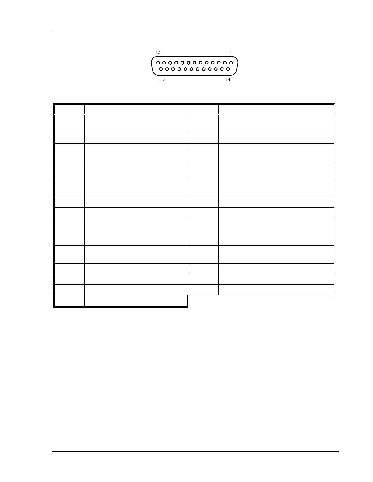
DLM-E 3kW & 4kW Series Power Supplies Advanced Operation
Figure 4–1. J3 Connector
Pin No. Function Pin No. Function
1
2 Remote Shutdown Return (–) 15 +5 VDC Aux. Output
3 Remote OVP Programming Input 16
4
5
6 Status Indicator Return (–) 19 DC Voltage Monitor Output
7 Current Monitor Output 20 Remote/Local Voltage Control Select
8
9 Voltage Programming Input 22
10 Current Programming Input 23 Remote/Local Current Control Select
11 N/C 24 N/C
12 Programming/Monitor Return (–) 25 N/C
Remote Output Enable
1 = Enable, 0 = Disable
Remote Programming Indicator
1 = Remote, 0 = Local
Operating Mode Indicator
1 = Volt mode, 0 = Current mode
N/C – for all models , except
16V, 22V models – Fault signal,
Active High, 10mA current source
14
17
18
21
Remote Shutdown Input (+). Positive or
negative true logic selection with S1
1 mA current source for OVP
Programming
OVP Status Indicator
1 = OVP Shutdown, 0 = Normal
Overtemp Shutdown Indicator
1 = OTP Shutdown, 0 = Normal
1 mA current source for Voltage
Programming
1 mA current source for Current
Programming
13 N/C
Table 4–1. J3 Connector – Program, Control, and Monitor Description
(D–subminiature 25–Pin Female)
4.2.2 Rear Panel DIP Switch
Switch S1 is located on the main printed circuit board and is able to be changed through the
rear panel of the power supply. The J3 connector is located on the unit's rear panel. See
Section 4.2.3 Resetting Rear Panel DIP Switch Settings and Section 4.2.4 Making J3
Connections.
M362000-01 Rev E
4-3
Page 48

Advanced Operation DLM-E 3kW & 4kW Series Power Supplies
Figure 4–2. Locating Jumpers, Switch, and Connector
Switch
Position
S1-1 Voltage Programming Input Range 0–5 VDC 0–10 VDC
S1-2 Current Programming Input Range 0–5 VDC 0–10 VDC
S1-3 OVP Programming Input Range 0–5 VDC 0–10 VDC
S1-4 Voltage Monitor Output Range 0–5 VDC 0–10 VDC
S1-5 Current Monitor Output Range 0–5 VDC 0–10 VDC
S1-6 Remote Shutdown Activation Active High Signal Active Low Signal
S1-7 Master/Slave Parallel Output Enable Single or Master Slave
S1-8 Front Panel Lockout Normal Lockout Mode
* Factory default position
Table 4–2. Rear Panel S1 DIP Switch Functions and Settings
Function
Open Position
(Up) *
Closed Position
(Down)
4.2.3 Resetting Rear Panel DIP Switch Settings
Some applications require the default factory settings of the rear panel 8–position DIP switch,
S1. If the switch requires resetting, read Section 2.2, and follow the procedures in this section.
Always turn off the front panel power switch before moving any DIP switch settings.
4.2.4 Making J3 Connections
The default factory configuration of the J3 connector has no jumpers. Other applications will
require placing pin–to–pin connections or making connections to external devices such as
voltage sources, or resistances. Read Section 2.2 Safety, and follow the procedures in this
section whenever the rear panel connector, J3, is to be reconfigured. Always turn off the front
panel power switch before soldering to the J3 connector, and only solder with the mating
connector removed from the supply.
4-4 M362000-01 Rev E
Page 49

DLM-E 3kW & 4kW Series Power Supplies Advanced Operation
Making the Connection
To make pin–to–pin connections:
1. Unsolder any unnecessary pin–to–pin jumpers as required by the application.
2. Solder new connections using any appropriate single bus wire such as AWG 20 to 24.
To connect external source leads, resistance leads, or monitoring lines:
3. Unsolder any unnecessary jumpers as required by the application.
4. Solder leads to the specified pin using the recommended wiring and/or grounding point
for the application. Pin, wiring, and grounding specifications for particular applications
can be found in Section 4. Advanced Operation except for remote sensing specifications
which are in Section 3.3 Using Remote Sensing.
NOTE
When the front panel LOCAL/REMOTE Switch is moved to REMOTE operation,
voltage, current, and OVP programming functions must be remotely programmed.
For clarity, only the connections for the function being described are shown in the
following figures.
4.3 Remote Programming of Output Voltage and
Current Limit
Remote programming allows control of the power supply's output voltage and/or current limit to
shift from local operation at the front panel voltage and current controls to external analog input
sources. As a programming source is varied, the power supply's output varies proportionally
over its output range.
The analog programming signals are connected to the rear panel J3 connector. To provide the
lowest noise performance, shielded–twisted pair wiring is recommended for making
connections from external circuits to the J3 connector. Use the shortest leads possible.
Ground the shield to pin 12 on the J3 connector or to the chassis via one of the J3 connector
screws.
CAUTION!
The remote programming input is internally referenced to the supply's
negative output. Do not connect remote programming input lines
(J3 pins 9 & 10) to the supply's positive output.
Remote Programming Options
The following table summarizes access options for programming output voltage and current limit
with the input scales supported for the DLM–E Series supply. Refer to Section 4.3.1 for a
procedure and a connection diagram for programming output voltage and current limit using the
REMOTE/LOCAL switch. Subsequent sections provide short procedures and diagram the J3
M362000-01 Rev E
4-5
Page 50

Advanced Operation DLM-E 3kW & 4kW Series Power Supplies
connector configurations and connections required for remote programming of output voltage
and/or current limit without using the REMOTE/LOCAL switch.
Remote Programming Options Control of ... Programming Scales *
Programming with the
REMOTE/LOCAL Switch
Programming without the
REMOTE/LOCAL Switch
(Jumper J3 Connector)
* These scales may be used in any combination
Output Voltage
Current Limit
Over Voltage Setting
Output Voltage and/or
Current Limit
0–5V, 0–10V, 0–5K
0–5V, 0–10V, 0–5K
Local control
4.3.1 Programming Output Voltage and Current Limit with the
REMOTE/LOCAL Switch
The front panel REMOTE/LOCAL Programming switch will allow you to switch back and forth
between remote and local operation when programming output voltage and current limit with
external voltage and/or current sources.
For programming output voltage and current limit using the REMOTE/LOCAL switch:
1. Connect a programming source between pins 9 (voltage programming input/positive)
and 12 (return).
2. Connect a programming source between pins 10 (current limit programming
input/positive) and 12 (return).
3. Connect a programming source between pins 3 (OVP programming input/positive) and
12 (return).
4. Connect a TTL high signal to Pin 1 (remote output enable). An external source must be
referenced to Pin 6 (common). Pin 15 (+5V) may be used as a source.
5. Set the front panel REMOTE/LOCAL switch to REM.
4-6 M362000-01 Rev E
Page 51

DLM-E 3kW & 4kW Series Power Supplies Advanced Operation
Figure 4–3. Programming Output Voltage, Current Limit and OVP with REM/LOC Switch
M362000-01 Rev E
4-7
Page 52

Advanced Operation DLM-E 3kW & 4kW Series Power Supplies
4.3.2 Programming Output Voltage
Programming Output Voltage with a 0–5 VDC or 0–10 VDC Source
1. Set S1-1, the rear panel DIP Switch, UP, in the open position for 0–5 VDC programming
range.
2. Set S1-1, the rear panel DIP Switch, DOWN, in the closed position for 0–10 VDC
programming range.
3. Connect the external programming source between pins 9 (voltage programming
input/positive) and 12 (return). Varying the programming voltage from 0 to maximum will
cause the output to vary from 0 to 100% of the model rating. Adjust the programming
signal to zero.
4. Turn the power supply ON.
5. Set the front panel LOCAL/REMOTE switch to the REMOTE position and adjust the
external programming source voltage. By pressing the V&I PREVIEW button and
observing the front panel voltmeter reading, the external control can be adjusted to the
desired setting.
S1 Switch Settings
S1-1 OPEN = 0–5V
S1-1 CLOSED = 0–10V
Figure 4–4. Programming Output Voltage with a 0–5 VDC or 0–10 VDC Source
4-8 M362000-01 Rev E
Page 53

DLM-E 3kW & 4kW Series Power Supplies Advanced Operation
Programming Output Voltage with Resistance
1. Set S1-1, the rear panel DIP Switch, UP, in the open position for 0–5k ohm programming
range.
2. Connect pins 9 (voltage programming input/positive) and 21 (1mA current source for
voltage control) to the counter–clockwise end of the potentiometer and connect the tap
and clockwise end of the potentiometer to pin 12 (return). Adjusting the resistance from
0 to maximum will vary the output voltage from 0 to 100% of the model rating. Adjust the
programming signal to zero.
3. Turn the power supply ON.
4. Set the front panel LOCAL/REMOTE switch to the REMOTE position and adjust the
external programming resistance. By pressing the V&I PREVIEW button and observing
the front panel voltmeter reading, the external control can be adjusted to the desired
setting.
S1 Switch Settings
S1-1 OPEN = 0–5K
Figure 4–5. Programming Output Voltage with a 0–5k Ohm Resistance
M362000-01 Rev E
4-9
Page 54

Advanced Operation DLM-E 3kW & 4kW Series Power Supplies
4.3.3 Programming Output Current Limit
Programming Output Current Limit with a 0–5 VDC or 0–10 VDC Source
1. Set S1-2, the rear panel DIP Switch, UP, in the open position for 0–5 VDC programming
range.
2. Set S1-2, the rear panel DIP Switch, Down, in the closed position for 0–10 VDC
programming range.
3. Connect the external programming source between pins 10 (current programming
input/positive) and 12 (return). Varying the programming voltage from 0 to maximum will
cause the output to vary from 0 to 100% of the model rating. Adjust the programming
signal to zero.
4. Turn the power supply ON.
5. Set the front panel LOCAL/REMOTE switch to the REMOTE position and adjust the
external programming voltage source. By pressing the V&I PREVIEW button and
observing the front panel ammeter reading, the external control can be adjusted to the
desired setting.
S1 Switch Settings
S1-2 OPEN = 0–5V
S1-2 CLOSED = 0–10V
Figure 4–6. Programming Output Current Limit with a 0–5 VDC or 0–10 VDC Source
4-10 M362000-01 Rev E
Page 55

DLM-E 3kW & 4kW Series Power Supplies Advanced Operation
Programming Output Current Limit with a 0–5k Ohm Resistance
1. Set S1-2, the rear panel DIP Switch, UP, in the open position for 0–5k ohm programming
range.
2. Connect pins 10 (current programming input/positive) and 22 (1mA current source for
current control) to the counter–clockwise end of the potentiometer and connect the tap
and clockwise end of the potentiometer to pin 12 (return). Adjusting the resistance from
zero to maximum will vary the output voltage from 0 to 100% of the model rating. Adjust
the programming signal to zero.
3. Turn the power supply ON.
4. Set the front panel LOCAL/REMOTE switch to the REMOTE position and adjust the
external programming resistance. By pressing the V&I PREVIEW button and observing
the front panel ammeter reading, the external control can be adjusted to the desired
setting.
S1 Switch Settings
S1-2 OPEN = 0–5K
Figure 4–7. Programming Output Current Limit with a 0–5k Ohm Resistance
M362000-01 Rev E
4-11
Page 56

Advanced Operation DLM-E 3kW & 4kW Series Power Supplies
4.3.4 Remote Programming Only the Output Voltage or Current Limit
The front panel REMOTE/LOCAL switch allows you to switch back and forth between remote
and local programming signals for all three programming inputs of Voltage, Current, and OVP.
When operation is desired for programming only the output voltage and/or current limit without
the other, or to leave the OVP control on the front panel, follow the procedures below:
Remote Programming of the Output Voltage Only
For remote programming of output voltage only:
1. Turn off power to the supply.
2. Connect a programming source to remote programming connector J3 between pins 9
(voltage programming input/positive) and 12 (return).
3. Connect a jumper between remote programming connector pins J3-20 and J3-21 for
external control of output voltage.
4. Adjust the external programming signal to zero.
5. Switch the ENABLE/STANDBY switch to STANDBY.
6. Turn the power supply ON.
7. Set the front panel LOCAL/REMOTE switch to the LOCAL position and adjust the
external programming signal. By pressing the V&I PREVIEW button and observing the
front panel voltmeter reading, the external control can be adjusted to the desired setting.
8. Adjust the current and OVP controls to the desired settings with the front panel controls
9. Switch the ENABLE/STANDBY switch to ENABLE.
10. The output voltage is now remotely programmed with local control of the current limit
and OVP settings.
S1 Switch Settings
S1-1 OPEN = 0–5V
S1-1 CLOSED = 0–10V
Figure 4–8. Programming Output Voltage Remotely, Local Control of Current Limit/OVP
4-12 M362000-01 Rev E
Page 57

DLM-E 3kW & 4kW Series Power Supplies Advanced Operation
Remote Programming of the Current Limit Only
CAUTION!
Always remove J3 mating connector from supply before soldering.
For remote programming of current limit only:
1. Turn off power to the supply.
2. Connect a programming source between pins 10 (current limit programming
input/positive) and 12 (return).
3. Connect a jumper between remote programming connector pins J3-22 and J3-23 for
external control of the current limit.
4. Adjust the external programming signal to zero.
5. Switch the ENABLE/STANDBY switch to STANDBY.
6. Turn the power supply ON.
7. Set the front panel LOCAL/REMOTE switch to the LOCAL position and adjust the
external programming signal. By pressing the V&I PREVIEW button and observing the
front panel ammeter reading, the external control can be adjusted to the desired setting.
8. Adjust the voltage and OVP controls to the desired settings with the front panel controls.
9. Switch the ENABLE/STANDBY switch to ENABLE.
10. The current limit setting is now remotely programmed with local control of the output
voltage and OVP settings.
S1 Switch Settings
S1-2 OPEN = 0–5V
S1-2 CLOSED = 0–10V
Figure 4–9. Programming Output Current Remotely, Local Control of Voltage Limit/OVP
M362000-01 Rev E
4-13
Page 58

Advanced Operation DLM-E 3kW & 4kW Series Power Supplies
4.4 Using Over Voltage Protection (OVP)
The OVP circuit allows for protection of the load in the event of a remote programming error, an
incorrect voltage control adjustment, or a power supply failure. The protection circuit monitors
the output voltage and will reduce the output current and voltage to zero whenever a preset
voltage limit is exceeded. The preset voltage limit, also called the set point or trip level, can be
set either in local programming mode from the front panel or by remote programming through
the J3 connector on the rear panel.
The red OVP LED on the front panel will light up when the OVP circuit has been activated.
4.4.1 Front Panel OVP Operation
In local programming mode, the OVP set point can be checked at any time by pressing the OVP
PREVIEW switch: The OVP set point is the value displayed on the digital voltmeter.
To set the trip level from the front panel:
1. Adjust the power supply output to zero volts.
2. Press the OVP PREVIEW switch to observe the OVP set point on the voltmeter display.
3. Turn the OVP SET potentiometer until the desired set point is reached. Release the
OVP CHECK switch.
4. Increase the power supply output voltage to check that the power supply shuts off the
output at the selected set point.
4.4.2 Resetting the OVP Circuit
To reset the OVP circuit after it has been activated:
1. Reduce the power supply's output voltage setting to below the OVP set point.
2. Press the ENABLE/STANDBY switch to the STANDBY position.
3. Return the ENABLE/STANDBY switch to the ENABLE position and resume normal
operation.
or
1. Reduce the power supply's output voltage setting to below the OVP set point.
2. Turn the power supply OFF using the POWER switch, then turn it back ON again.
4-14 M362000-01 Rev E
Page 59

DLM-E 3kW & 4kW Series Power Supplies Advanced Operation
4.4.3 Programming OVP with an External Voltage Source
CAUTION!
Always remove J3 mating connector from supply before soldering.
Programming OVP with a 0–5 VDC or 0–10 VDC Source
1. Set S1-3, the rear panel DIP Switch, UP, in the open position for 0–5 VDC programming
range.
2. Set S1-3, the rear panel DIP Switch, DOWN, in the closed position for 0–10 VDC
programming range.
3. Connect the external programming source between pins 3 (OVP programming
input/positive) and 12 (return). Varying the programming voltage from zero to maximum
will cause the OVP setting to vary from approximately 0 to 110% of the model rating.
4. Turn the power supply ON and adjust the external voltage programming to zero.
5. Set the front panel LOCAL/REMOTE switch to the REMOTE position and adjust the
external OVP programming source voltage. By pressing the OVP PREVIEW button and
looking at the front panel voltmeter setting, the external control can be adjusted to the
desired value.
6. Slowly increase the external output voltage programming signal until the red OVP LED
lights and the power supply shuts down.
S1 Switch Settings
S1-3 OPEN = 0–5V
S1-3 CLOSED = 0–10V
Figure 4–10. Remote Programming of OVP with a 0–5 VDC or 0–10 VDC
M362000-01 Rev E
External Voltage Source
4-15
Page 60

Advanced Operation DLM-E 3kW & 4kW Series Power Supplies
Programming OVP with a 0–5k Ohm Resistance
1. Set S1-3, the rear panel DIP Switch, UP, in the open position for 0–5 k ohm
programming range.
2. Connect the external programming source between pins 3 (OVP programming
input/positive) and 12 (return). Varying the programming voltage from zero to maximum
will cause the OVP setting to vary from approximately 0 to 110% of the model rating.
3. Connect pins 3 (OVP programming input/positive) and 16 (1mA current source for OVP
control) of J3 to the counter–clockwise end of the potentiometer and connect the tap and
clockwise end of the potentiometer to pin 12 (return). Adjusting the resistance from zero
to maximum will vary the output voltage from approximately 0 to 110% of the model
rating.
4. Turn the power supply ON and adjust the external voltage programming input to zero.
5. Set the front panel LOCAL/REMOTE switch to the REMOTE position and adjust the
external OVP programming source voltage. By pressing the OVP PREVIEW button and
looking at the front panel voltmeter setting, the external control can be adjusted to the
desired value.
6. Slowly increase the external output voltage programming signal until the red OVP LED
lights and the power supply shuts down.
S1 Switch Settings
S1-3 OPEN = 0–5K
Figure 4–11. Remote Programming of OVP with a 0–5k ohm Resistance
4-16 M362000-01 Rev E
Page 61

DLM-E 3kW & 4kW Series Power Supplies Advanced Operation
4.5 Using the Shutdown Function
The Shutdown function is used to disable or enable the supply's output voltage and current. It
can be used to allow adjustments to be made to either the load or the power supply without
shutting off the entire supply. This function may be activated from the front panel at any time by
using the STANDBY switch. It can also be activated via remote programming, using positive or
negative logic, with a TTL compatible input or higher DC signal.
4.5.1 STANDBY Switch
The STANDBY switch is a two–position rocker switch located on the power supply's front panel.
See the front panel diagram in Section 2. When in the STANDBY position, the shutdown circuit
is activated, and the output voltage and current are programmed to zero. Pushing the switch to
the ENABLE position allows normal power supply operation to resume.
4.5.2 Programming the Shutdown Function
The Shutdown circuit uses a 5–24 VDC input to disable or enable the power supply output.
Connections for the input signals are made on connector J3. Rear panel DIP switch S1-6,
determines whether positive or negative logic for the signal is used. The input lines for the
Shutdown circuit are optically isolated and can therefore be used by input sources with a
voltage differential of up to +/– 150 VDC.
External Wiring
Use 20 to 24 AWG wiring when making connections to the J3 connector. Keep wiring as short
as possible.
TTL Shutdown
To activate the Shutdown function using a DC input:
1. Turn off the power supply.
2. Connect the signal source to J3 pin 14 (Remote Shutdown Input/positive) and J3 pin 2
(Return for Shutdown Input) on the J3 connector on the rear panel. See Figure 4–12.
3. Set internal switch SW1-6 to select the desired circuit logic as defined in the following
table.
Switch S1-6 Setting Signal Level Output Condition
UP/Open = Positive Logic
DOWN/Closed = Negative Logic
High
Low
High
Low
OFF
ON
ON
OFF
The red S/D (Shutdown) LED on the front panel lights up when the Shutdown circuit is
activated.
M362000-01 Rev E
4-17
Page 62

Advanced Operation DLM-E 3kW & 4kW Series Power Supplies
Figure 4–12. Using Shutdown with a DC Input (Positive Logic)
4.5.3 Shutdown Application – Contact Closure
An external relay, whether normally open or normally closed, may be used to activate the
Shutdown circuit. Either positive or negative logic may be used.
To activate the Shutdown function using an external relay:
1. Turn off the power supply.
2. Connect one side of the external relay to pin 15 (+5 VDC Auxiliary Output) on connector
J3. Connect the other side of the relay to J3-pin 14 (Remote Shutdown Input). Also
connect pin 2 (Shutdown Return) to pin 6 (Status Indicator Return). See Figure 4–13
through Figure 4–16.
3. Set rear panel DIP switch S1 to select the desired circuit logic as defined in the following
table.
Relay Switch S1-6 Setting Relay Coil State Output
UP–Open (Positive Logic)
Normally Open Relay
DOWN–Closed (Negative Logic)
UP–Open (Positive Logic)
Normally Closed Relay
DOWN–Closed (Negative Logic)
Energized OFF
De-energized ON
Energized ON
De-energized OFF
Energized ON
De-energized OFF
Energized OFF
De-energized ON
The red S/D (Shutdown) LED on the front panel lights up when the Shutdown circuit is
activated.
4-18 M362000-01 Rev E
Page 63

DLM-E 3kW & 4kW Series Power Supplies Advanced Operation
Figure 4–13.
Figure 4–14.
Using Shutdown with Contact Closure of a Normally OPEN Relay (S1-6 Up)
Using Shutdown with Contact Closure of a Normally OPEN Relay (S1-6 Down)
Figure 4–15.
Using Shutdown with Contact Closure of a Normally CLOSED Relay (S1-6 Up)
M362000-01 Rev E
4-19
Page 64

Advanced Operation DLM-E 3kW & 4kW Series Power Supplies
Figure 4–16.
Using Shutdown with Contact Closure of Normally CLOSED Relay (S1-6 Down)
4.6 Remote Monitoring
4.6.1 Readback Signals
Calibrated readback signals for remote monitoring of the output voltage and current are
available via connections at the J3 connector on the rear panel. Rear panel DIP switch S1
settings allow you to select either a 0–5 VDC or a 0–10 VDC range for the output. See
Section 4.2 Configuring for Remote Programming, Sensing, and Monitoring for more information
about making these connections.
The following table shows the required pin connections and switch settings for remote
monitoring of readback signals with 0–5 VDC or 0–10 VDC outputs. Use shielded–twisted pair
wiring (20 to 24 AWG) and ground the shield to J3 connector pin 6 or to the chassis via one of
the J3 connector screws. The readback signal represents 0 to 100% of the model–rated
output.
Readback
Signal
Voltage Monitor Pin 19 Pin 12 S1–4
J3 Connections
Signal (+) Return (–)
Switch S1 Settings
Switch # Setting
UP
DOWN
Output Signal:
Range
0–5 VDC
0–10 VDC
Current Monitor Pin 7 Pin 12 S1–5
CAUTION!
Always remove J3 mating connector from supply before soldering.
4-20 M362000-01 Rev E
UP
DOWN
0–5 VDC
0–10 VDC
Page 65

DLM-E 3kW & 4kW Series Power Supplies Advanced Operation
4.6.2 Status Indicators
Status indicators for thermal shutdown, OVP circuit, programming mode, and operating mode
are available via connections on the J3 connector on the rear panel.
The following table shows the indicator signals, the J3 connector pin at which they are
available, an approximation of the signal magnitude, and the source impedance through which
the signal is fed. Use 20 to 24 AWG wiring.
Indicator Signal /
Alternate State
Overtemperature Shutdown /
Normal Operation
OVP Circuit Activated /
OVP Circuit Not Activated
Remote Programming Mode /
Local Programming Mode
Voltage Mode Operation /
Current Mode Operation
J3 Connections
Signal (+) Return (–)
Pin 18
Pin 18
Pin 17
Pin 17
Pin 4
Pin 4
Pin 5
Pin 5
Pin 6
Pin 6
Pin 6
Pin 6
Pin 6
Pin 6
Pin 6
Pin 6
Signal
Voltage
+5V
0V
+5V
0V
+5V
0V
+5V
0V
Source
Impedance
1k ohms
1k ohms
1k ohms
1k ohms
1k ohms
1k ohms
1k ohms
1k ohms
4.7 Using Multiple Supplies
DLM–E Series power supplies of the SAME MODEL may be operated with outputs in series or
in parallel to obtain increased load voltage or increased current. Split supply operation allows
two positive or a positive and a negative output to be obtained. The power supply output may be
biased up to a maximum of 150 VDC with respect to the chassis.
WARNING!
Use extreme caution when biasing the output relative to the chassis due to
potentially high voltage levels at the output and J3 terminals.
Do not attempt to bias program/monitor signal lines on the J3 connector relative to the power
supplies positive output. The signal returns on the J3 program/monitor connector are at the
same potential as the power supply return bus bar in a standard unit. Using the Isolated
Programming Interface option allows control from a programming source biased relative to the
supply’s output. Contact factory for additional details.
4.7.1 Configuring Multiple Supplies for Series Operation
Series operation will obtain a higher voltage from a single output using two or more supplies.
Connect the negative (–) output terminal of one supply to the positive (+) output terminal of the
next supply. See Figure 4–17. The total voltage available is the sum of the maximum voltages of
each supply (add voltmeter readings). The maximum allowable current for a series string of
power supplies is the model rated output current of a single supply in the string.
Note: The maximum allowable sum of the output voltages is 300 VDC. This is limited by the
voltage rating of certain internal components. See Section 1 for maximum voltage rating.
M362000-01 Rev E
4-21
Page 66

Advanced Operation DLM-E 3kW & 4kW Series Power Supplies
CAUTION!
Remote sensing must not be used during series operation.
CAUTION!
The remote programming input is internally referenced to the supply's
negative output. Do not connect any remote programming input lines on the
J3 connector to the supply's positive output.
Figure 4–17. Series Operation of Multiple Supplies
(Local sense lines shown are default J11 to busbar connections)
4.7.2 Configuring Multiple Supplies for Split Supply Operation
Split supply operation uses two power supplies to obtain two positive voltages with a common
ground, or to obtain a positive–negative supply.
To obtain two positive voltages, connect the negative output terminals of both supplies
together. The positive output terminals will provide the required voltages with respect to the
common connection. See Figure 4–18.
To obtain a positive–negative supply, connect the negative output terminal of one supply to
the positive output terminal of the second supply. The positive output terminal of the first supply
then provides a positive voltage relative to the common connection while the negative output
terminal of the second supply provides a negative voltage. The current limits can be set
independently. The maximum current available in split supply operation is equal to the model–
rated output of the supplies used. See Figure 4–19.
4-22 M362000-01 Rev E
Page 67

DLM-E 3kW & 4kW Series Power Supplies Advanced Operation
CAUTION!
To prevent possible damage to the supply, do not connect the remote
program return line of the negative supply to the common connection.
Figure 4–18. Split Supply Operation of Multiple Supplies (Two Positive Voltages)
(Local sense lines shown are from J11 to busbars)
Figure 4–19. Split Supply Operation of Multiple Supplies (Positive–Negative Supply)
(Local sense lines shown are from J11 to busbars)
M362000-01 Rev E
4-23
Page 68

Advanced Operation DLM-E 3kW & 4kW Series Power Supplies
4.7.3 Configuring Multiple Supplies for Parallel Operation
Parallel operation is used to obtain a higher current output supply using up to five units. The
DLM–E supplies are designed to be easily paralleled with current sharing between units with the
use of a simple cable between supplies. See Figure 4–20.
Notes:
1. Set the rear panel switch S1–7 down on the Slave unit(s) only. This allows for full
control of the output voltage, current, and OVP trip level through one Master supply.
2. To control the slaves, plug the Master/Slave cable into J12 of the Master supply and
into J13 of the first Slave supply.
3. Plug an identical cable into J12 on this slave and connect to J13 on any subsequent
Slave supplies as required until all supplies in the Master/Slave set have a cable
plugged into either J12 or J13 or both.
4. Ensure that all of the outputs of the positive terminals (+) and negative terminals (–)
are also connected in parallel. Refer to Section 2.8 for a discussion on the proper
method for connecting to the load.
5. The total current available is the sum of the maximum currents of each supply. Each
supply will read back the portion of current that it is supplying to the load and these
must be added together to get the total load current.
CAUTION!
To prevent internal damage, ensure that the Master/Slave Parallel Output
Enable switch S1–7 is Up on the Master supply and Down on all Slaves.
There can be only one Master supply!
Pin Number Function Voltage Level
1 Parallel OVP Control 0–5 V
2 Parallel Current Command 0–7V
3 Parallel Command Return (–) 0V
4 Parallel Voltage Control 0–5V
5 Parallel Output Command 5V
6 Programming/Monitor Return (–) 0V
Table 4–3. J12, J13 Connectors–Parallel Port Function and Pinout
4-24 M362000-01 Rev E
Page 69

DLM-E 3kW & 4kW Series Power Supplies Advanced Operation
Figure 4–20. Parallel Operation of Multiple Supplies
(Local sense lines shown are from J11 to busbars)
4.8 Front Panel Lockout
The front panel lockout mode enables a user to disable the front panel controls when the unit is
being programmed exclusively through the J3 remote input connector. To activate the front
panel lockouts, push the front panel LOCAL/REMOTE switch to the REMOTE position with the
S1 rear panel Dip switch S1–8 in the down or closed position. Once the lock function has been
activated, it disables local control for all output control functions, except the AC power switch,
which remains under front panel control and lights the front panel LOCK LED.
4.9 Fault Alarm Signal
Active high state in converter indicates over temperature, over voltage protection (OVP), or
internal shutdown. The Fault signal is the summary of protection. Circuits return J3-6 (Status
Indicator Return). This terminal goes to low state when the converter is operating under normal
conditions.
M362000-01 Rev E
4-25
Page 70

Advanced Operation DLM-E 3kW & 4kW Series Power Supplies
This page intentionally left blank.
4-26 M362000-01 Rev E
Page 71

SECTION 5
MAINTENANCE AND
TROUBLESHOOTING
5.1 Periodic Service
This section provides periodic maintenance, calibration and troubleshooting information.
Except for periodic cleaning and calibration, no routine service is required. Whenever a unit
is removed from service, it should be cleaned, using denatured or isopropyl alcohol or an
equivalent solvent on the metal surfaces, and a weak solution of soap and water for the front
panel. Low pressure compressed air may be used to blow dust from in and around
components on the printed circuit boards.
5.2 Troubleshooting
Units requiring repair during their warranty period should be returned to the manufacturer for
service. Unauthorized repairs performed during the warranty period may void the warranty.
Please refer to the Warranty page in this manual for terms and contact information.
Potentially lethal voltage exists in the power circuit and the output of high voltage
models. Filter capacitors store potentially dangerous energy for some time after
power is removed. Only experienced technical personnel should make repairs.
Be sure to isolate the power supply from the input line with an isolation transformer
when using grounded test equipment such as an oscilloscope in the power circuit.
5.2.1 Preliminary Checks
CAUTION!
If the power supply displays any unusual or erratic shut the power supply off immediately
and disconnect it from the AC power source. Check all loads, programming and monitoring
connections and circuits. Check the AC input for correct voltage and frequency. Correct any
problems found and retest the system. If no problems are found or the unit fails to operate
correctly upon re–testing proceed with internal troubleshooting as described below.
M362000-01 Rev E 5-1
Page 72

Maintenance and Troubleshooting DLM-E 3kW & 4kW Series Power Supplies
5.2.2 Troubleshooting at the Operation Level
Use the checks in Table 5–1 to ensure the DLM–E Series power supply is configured and
connected for default operation at the front panel. If you need any further troubleshooting, call
customer service.
Symptom Check Further Checks and Corrections
No output and the
display is blank
No output but the
display lights
Output not adjustable Is unit in current limit mode?
Is input voltage within specified
range?
Power switch ON? Turn on power.
Internal circuit? See your service technician.
OVP LED lit?
Front panel S/D LED lit?
OTEMP LED lit?
Current limit set to zero?
Voltage control set to zero?
REM LED lit?
Is front panel ON LED lit? Connect unit to AC supply in specified
Internal circuit. See your service technician.
(Green Current Mode LED lit.)
Is unit in REMOTE mode?
(Green REM LED lit.)
Connect to appropriate voltage
source. See Section 2.6.
See Section 2.4.1.
See Section 2.4.1.
See Section 2.4.1.
See Section 3.2.2.
See Section 3.2.2.
See Section 4.3.
range. See Section 2.4.1.
Turn current knob clockwise to
increase current limit. Reduce load if
current is at maximum. See
Section 3.2.1.
See Section 4.3.
Is unit in LOCK mode?
(Green LOCK LED lit.)
Is unit at maximum voltage or
current limit?
Output voltage
fluctuating
or regulation poor
Output oscillating Internal circui t. See your service technician.
Is unit at current limit? Increase current limit setting or reduce
Is input voltage within specified
range?
Are sense lines connected?
Is unit under remote analog
control?
Internal circuit. See your service technician.
See Section 4.8.
Reduce load for lower voltage or
current requirement.
load. See Section 3.2.1.
Connect to appropriate AC voltage
source. See Section 2.6.
See Section 2.8 and Section 3.3.
Ensure program source is stable.
Table 5–1. User Diagnostics
5-2 M362000-01 Rev E
Page 73
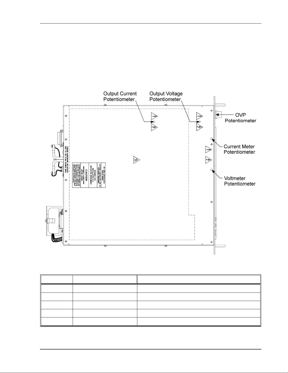
DLM-E 3kW & 4kW Series Power Supplies Maintenance and Troubleshooting
5.3 Calibration
Calibration of the output voltage, current, or OVP is accomplished using multiturn trimpots.
Table 5–2 gives the location, function, and effect of each potentiometer.
Calibration is performed at the factory during testing. Recalibration should be performed
annually and following major repairs. With the cover in place, calibration should be done
through access holes in the cover or front panel. See Figure 5–1.
Figure 5–1. Potentiometer Locations
Location Function Adjustment Procedure
Top Cover Output Voltage Clockwise rotation increases output voltage setting
Top Cover Output Current Clockwise rotation increases output current setting
Top Cover Front Panel Voltmeter Clockwise rotation increases voltage meter reading
Top Cover Front Panel Current Meter Clockwise rotation increases current meter reading
Front Panel OVP Clockwise rotation increases OVP shutdown setting
Table 5–2. Potentiometer Adjustment Procedures
M362000-01 Rev E
5-3
Page 74

Maintenance and Troubleshooting DLM-E 3kW & 4kW Series Power Supplies
5.4 Ordering Parts
Do not substitute parts without first checking with the manufacturer’s Service Department. Parts
may be ordered from the factory , using the following information:
AMETEK Programmable Power
9250 Brown Deer Road
San Diego, CA 92121-2294
Toll free in North America: 1-800-733-5427
Direct: (858) 450-0085
Fax: (858) 458-0267
E-mail: sales@programmablepower.com
www.programmablepower.com
Note: When ordering parts please include the model number and serial number of the unit with
your order.
5.5 Fuse Ratings
Table 5–3 provides a listing of Fuse Ratings.
Reference Designator Fuse Type Rating Size Option
F1, 2, 3 (Rear Panel) Fast Acting, AC F, 25A, 600V 13/32" x 1½ Std
F1, 2, 3 (Rear Panel) Fast Acting, AC F, 10A, 600V 13/32" x 1½ M1
F1, 2, 3 (Rear Panel) Fast Acting, AC F, 8A, 600V 13/32" x 1½ M2
F1 (Inside Chassis) Fast Acting, DC F, 15A, 600V 13/32" x 1½ —
F5, 6 Slow Blow, AC 2A, 250V 5 x 20 mm Leaded —
F7 Fast Acting, DC 0.5A, 125V PCB —
Table 5–3. Fuse Ratings
5-4 M362000-01 Rev E
 Loading...