

Page 1

DLM 600W Series
Power Supplies
M51A Option Isolated Analog
Programming Manual
M362299-01 Rev B www.programmablepower.com
Page 2

Page 3

About AMETEK
AMETEK Programmable Power, Inc., a Division of AMETEK, Inc., is a global leader in the design
and manufacture of precision, programmable power supplies for R&D, test and measurement,
process control, power bus simulation and power conditioning applications across diverse
industrial segments. From bench top supplies to rack-mounted industrial power subsystems,
AMETEK Programmable Power is the proud manufacturer of Elgar, Sorensen, California
Instruments and Power Ten brand power supplies.
AMETEK, Inc. is a leading global manufacturer of electronic instruments and electromec hanical
devices with annualized sales of $2.5 billion. The Company has over 11,000 colleagues working
at more than 80 manufacturing facilities and more than 80 sales and service centers in the United
States and around the world.
Trademarks
AMETEK is a registered trademark of AMETEK, Inc. Sorensen is a trademark owned by AMETEK, Inc.
Other trademarks, registered trademarks, and product names are the property of their respective
owners and are used herein for identification purposes only.
Notice of Copyright
DLM 600W Series Power Supplies M51A Option Isolated Analog Programming Manual
AMETEK Programmable Power, Inc. All rights reserved.
© 2002
Exclusion for Documentation
UNLESS SPECIFICALLY AGREED TO IN WRITING, AMETEK PROGRAMMABLE POWER, INC.
(“AMETEK”):
(a) MAKES NO WARRANTY AS TO THE ACCURACY, SUFFICIENCY OR SUITABILITY OF ANY
TECHNICAL OR OTHER INFORMATION PROVIDED IN ITS MANUALS OR OTHER
DOCUMENTATION.
(b) ASSUMES NO RESPONSIBILITY OR LIABILITY FOR LOSSES, DAMAGES, COSTS OR
EXPENSES, WHETHER SPECIAL, DIRECT, INDIRECT, CONSEQUENTIAL OR INCIDENTAL,
WHICH MIGHT ARISE OUT OF THE USE OF SUCH INFORMATION. THE USE OF ANY SUCH
INFORMATION WILL BE ENTIRELY AT THE USER’S RISK, AND
(c) REMINDS YOU THAT IF THIS MANUAL IS IN ANY LANGUAGE OTHER THAN ENGLISH,
ALTHOUGH STEPS HAVE BEEN TAKEN TO MAINTAIN THE ACCURACY OF TH E
TRANSLATION, THE ACCURACY CANNOT BE GUARANTEED. APPROVED AMETEK CONTENT
IS CONTAINED WITH THE ENGLISH LANGUAGE VERSION, WHICH IS POSTED AT
WWW.PROGRAMMABLEPOWER.COM.
Date and Revision
December 2008 Revision B
Part Number
M362299-01
Contact Information
Telephone: 800 733 5427 (toll free in North America)
858 450 0085 (direct)
Fax: 858 458 0267
Email: sales@programmablepower.com
service@programmablepower.com
Web: www.programmablepower.com
Page 4

This page intentionally left blank.
ii
Page 5
G
G
Important Safety Instructions
Before applying power to the system, verify that your product is configured properly for your
particular application.
WARNIN
WARNIN
Only qualified personnel who deal with attendant hazards in power supplies, are allowed to perform
installation and servicing.
Ensure that the AC power line ground is connected properly to the Power Rack input connector or
chassis. Similarly, other power ground lines including those to application and maintenance
equipment must be grounded properly for both personnel and equipment safety.
Always ensure that facility AC input power is de-energized prior to connecting or disconnecting any
cable.
In normal operation, the operator does not have access to hazardous voltages within the chassis.
However, depending on the user’s application configuration, HIGH VOLTAGES HAZARDOUS TO
HUMAN SAFETY may be normally generated on the output terminals. The customer/user must
ensure that the output power lines are labeled properly as to the safety hazards and that any
inadvertent contact with hazardous voltages is eliminated.
Guard against risks of electrical shock during open cover checks by not touching any portion of the
electrical circuits. Even when power is off, capacitors may retain an electrical charge. Use safety
glasses during open cover checks to avoid personal injury by any sudden component failure.
Neither AMETEK Programmable Power Inc., San Diego, California, USA, nor any of the subsidiary
sales organizations can accept any responsibility for personnel, material or inconsequential injury,
loss or damage that results from improper use of the equipment and accessories.
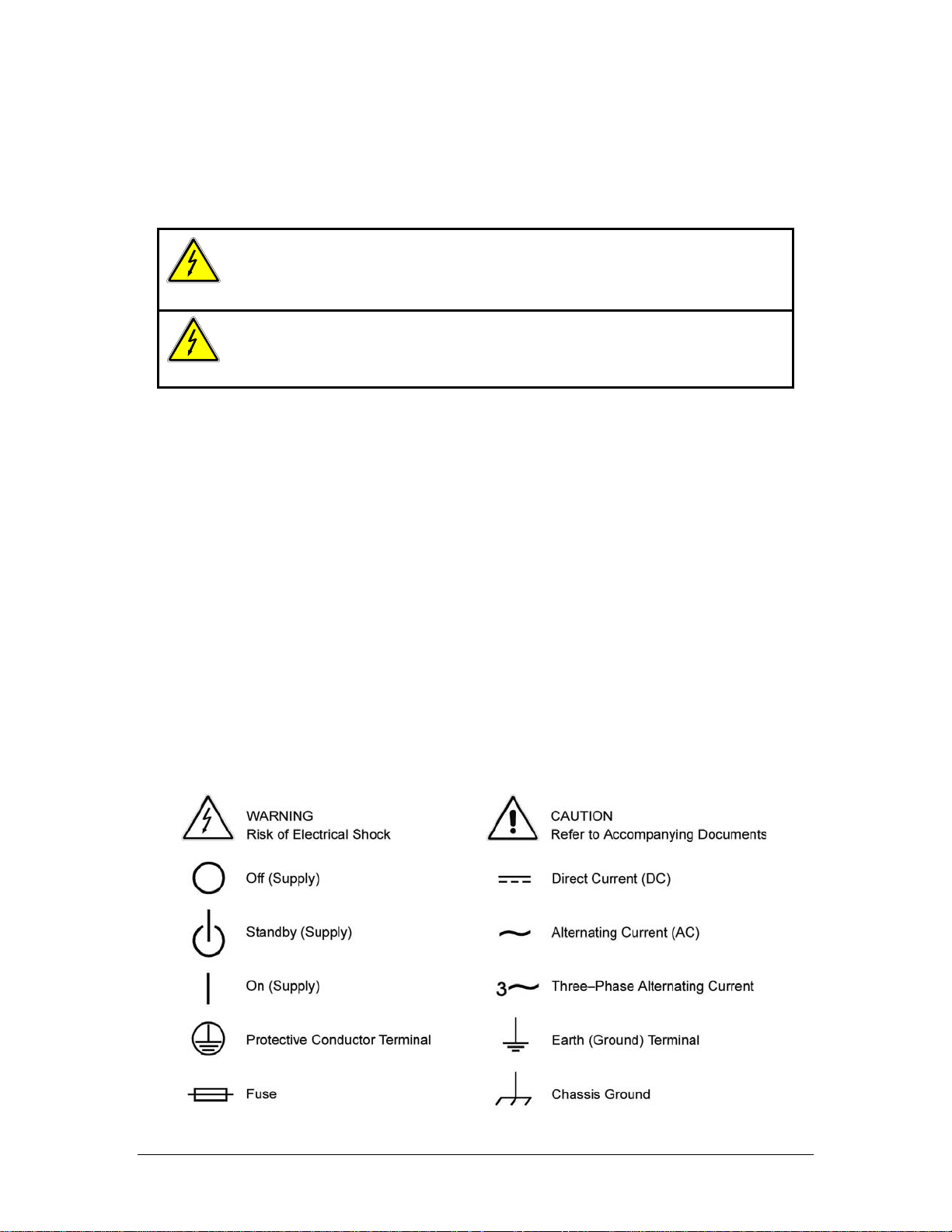
Hazardous voltages may be present when covers are removed. Qualified
personnel must use extreme caution when servicing this equipment.
Circuit boards, test points, and output voltages also may be floating above
(below) chassis ground.
The equipment used contains ESD sensitive parts. When installing
equipment, follow ESD Safety Procedures. Electrostatic discharges might
cause damage to the equipment.
SAFETY SYMBOLS
iii
Page 6

This page intentionally left blank.
iv
Page 7

Product Family: DLM 600W Series Power Supplies
Warranty Period: Five Years
WARRANTY TERMS
AMETEK Programmable Power, Inc. (“AMETEK”), provides this written warranty covering the
Product stated above, and if the Buyer discovers and notifies AMETEK in writing of any defect in
material or workmanship within the applicable warranty period stated above, then AMETEK may,
at its option: repair or replace the Product; or issue a credit note for the defective Product; or
provide the Buyer with replacement parts for the Product.
The Buyer will, at its expense, return the defective Product or parts thereof to AMETEK in
accordance with the return procedure specified below. AMETEK will, at its expense, deliver the
repaired or replaced Product or parts to the Buyer. Any warranty of AMETEK will not apply if the
Buyer is in default under the Purchase Order Agreement or where the Product or any part
thereof:
• is damaged by misuse, accident, negligence or failure to maintain the same as
specified or required by AMETEK;
• is damaged by modifications, alterations or attachments thereto which are not
authorized by AMETEK;
• is installed or operated contrary to the instructions of AMETEK;
• is opened, modified or disassembled in any way without AMETEK’s consent; or
• is used in combination with items, articles or materials not authorized by AMETEK.
The Buyer may not assert any claim that the Products are not in conformity with any warranty
until the Buyer has made all payments to AMETEK provided for in the Purchase Order Agreement.
PRODUCT RETURN PROCEDURE
1. Request a Return Material Authorization (RMA) number from the repair facility (must be
done in the country in which it was purchased):
• In the USA, contact the AMETEK Repair Department prior to the return of the
product to AMETEK for repair:
Telephone: 800-733-5427, ext. 2295 or ext. 2463 (toll free North America)
858-450-0085, ext. 2295 or ext. 2463 (direct)
• Outside the United States, contact the nearest Authorized Service Center
(ASC). A full listing can be found either through your local distributor or our
website, www.programmablepower.com, by clicking Support and going to the
Service Centers tab.
2. When requesting an RMA, have the following information ready:
• Model number
• Serial number
• Description of the problem
NOTE: Unauthorized returns will not be accepted and will be returned at the shipper’s expense.
NOTE: A returned product found upon inspection by AMETEK, to be in specification is subject to
an evaluation fee and applicable freight charges.
v
Page 8

This page intentionally left blank.
vi
Page 9

CONTENTS
SECTION 1 M51A OPTION OVERVIEW
1.1 Introduction ...................................................................................................... 1-1
1.2 General Description ......................................................................................... 1-1
1.3 Specifications................................................................................................... 1-2
1.3.1 Electrical Specifications ....................................................................... 1-2
1.3.2 Supplemental Characteristics .............................................................. 1-2
SECTION 2 ISOLATED REMOTE ANALOG INTERFACE OPERATION
2.1 INTFC SETUP Switch...................................................................................... 2-1
2.1.1 INTFC SETUP Switch Functions ......................................................... 2-2
2.2 SETUP Switch ................................................................................................. 2-2
2.3 Isolated Analog Interface Connector ............................................................... 2-3
2.3.1 ISOLATED ANALOG INTERFACE Functions ..................................... 2-5
2.4 Remote Programming Configuration ............................................................... 2-7
2.4.1 Voltage Source Programming of Output Voltage................................. 2-8
2.4.2 Voltage Source Programming of Output Current................................. 2-8
2.4.3 Voltage Source Programming of OVP ................................................. 2-8
2.4.4 Resistance Programming of Output Voltage ....................................... 2-9
2.4.5 Resistance Programming of Output Current........................................ 2-9
2.4.6 Resistance Programming of OVP...................................................... 2-10
2.4.7 4-20mA Current Source Programming of Output Voltage ................. 2-10
2.4.8 4-20mA Current Source Programming of Output Current.................. 2-10
2.5 EXTERNAL-OFF Control ............................................................................... 2-11
2.6 Remote Monitoring ........................................................................................ 2-11
2.7 Remote Digital Status Signals ....................................................................... 2-12
M51A Option vii
Page 10

Contents DLM 600W Series
LIST OF TABLES
Table 2–1. INTFC SETUP Switch............................................................................... 2-1
Table 2–2. ISOLATED ANALOG INTERFACE Connector Pinout .............................. 2-4
Table 2–3. Remote Programming Configuration Options ........................................... 2-7
Table 2–4. Remote Monitoring................................................................................. 2-11
Table 2–5. Remote Digital Status Signals ............................................................... 2-12
LIST OF FIGURES
Figure 2–1. Rear Panel View, Low–Voltage Models................................................... 2-3
Figure 2–2. Rear Panel View, High–Voltage Models.................................................. 2-3
viii M51A Option
Page 11

SECTION 1
M51A OPTION OVERVIEW
1.1 Introduction
This addendum is to be used in conjunction with the DLM 600W Series Power Supplies
Operation Manual, Sorensen Document No. M362161-01.
The Sorensen M51A Option for the DLM 600W Series power supplies provides a remote analog
interface, which has safety isolation from the output terminals. This allows the remote analog
interface to be connected to user accessible (SELV) control circuits, even though the output
terminals were floated at a high potential with respect to the chassis.
1.2 General Description
The M51A Option provides isolation for all programming, monitoring, and digital I/O signals that
are available through the remote analog interface. This isolation barrier eliminates the
connection that exists in the standard DLM models between the non-isolated remote interface
circuits and the output return (negative) terminal. The M51A Option remote analog signals are
referenced to chassis, and could be user accessible irrespective of the float potentials that exist
at the output terminals.
The M51A Option provides a full complement of programming, monitoring, and control methods.
Remote programming is available for output voltage, current, and overvoltage protection (OVP).
Analog output monitor signals are available for the output voltage and current. Digital I/O
signals provide indication of the operational state, and a means of enabling the remote interface
and the output.
The type and range of the control and monitor signals are user-selectable with a rear panel
setup switch. The output voltage, current, and OVP could be programmed with a 0-5VDC,
0-10VDC, or 0-5kΩ resistance; in addition, the output voltage and current could be programmed
with 4-20mA signals. The output voltage and current monitors could produce 0-5VDC,
0-10VDC, or 4-20mA signals. Isolated 1mA current sources are provided to facilitate the
utilization of 0-5kΩ programming resistances.
Except for the isolated remote analog interface, the installation and operation of the DLM 600W
Series power supplies remains as presented in the Operation Manual. The following sections
provide a detailed description of the new features and the differences in operation.
M51A Option 1-1
Page 12

M51A Option Overview DLM 600W Series
1.3 Specifications
1.3.1 Electrical Specifications
Remote Voltage Programming Accuracy, 0-5/10V Inputs:
Output Voltage: 0.5% of Vmax
Output Current: 0.75% of Imax
OVP: 1.0% of 1.1 X Vmax
Remote 4-20mA Programming Accuracy:
Output Voltage: 0.75% of Vmax
Output Current: 1.0% of Imax
1.3.2 Supplemental Characteristics
Remote Resistance Programming Accuracy, 0-5kΩ Input:
Output Voltage: 1.0% of Vmax
Output Current: 1.5% of Imax
OVP: 1.5% of 1.1 X Vmax
Remote Monitor Accuracy:
Output Voltage, 0-5/10V ranges: 0.5% of Vmax
Output Voltage, 4-20mA: 0.75% of Vmax
Output Current, 0-5/10V ranges: 0.75% of Imax
Output Current, 4-20mA: 1.0% of Imax
1-2 M51A Option
Page 13

SECTION 2
ISOLATED REMOTE ANALOG
INTERFACE OPERATION
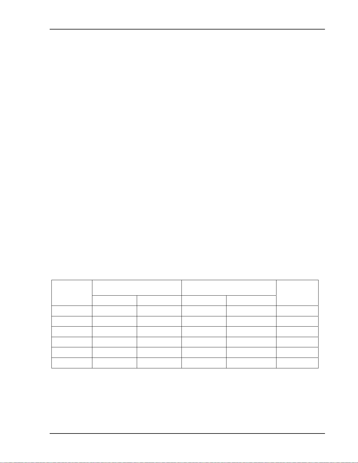
2.1 INTFC SETUP Switch
The INTFC SETUP (Interface Setup) switch is accessible from the rear panel of the unit. It
provides user selectability of the programming/monitoring ranges and signal types, as well as
configuring the power supply for operation under remote control. Setting a switch to the UP
position enables a function. The factory default settings are all switch positions OFF (down).
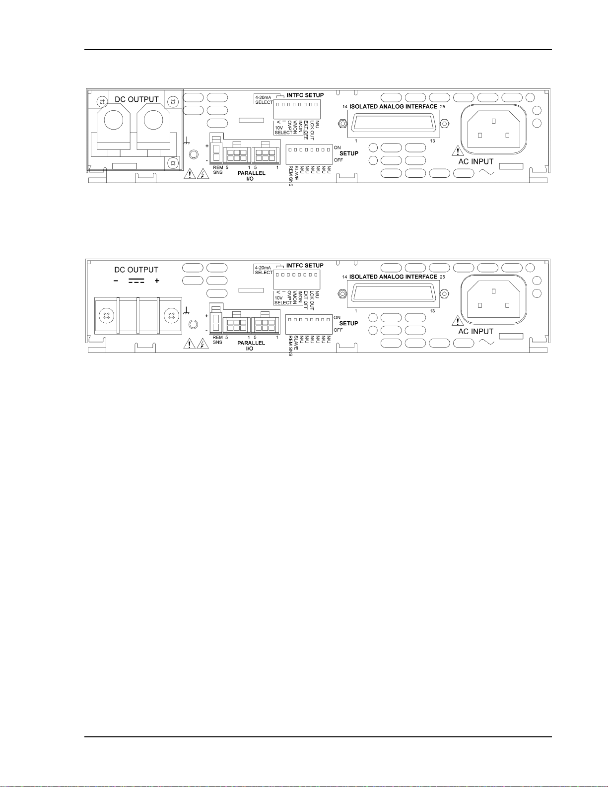
See Figure 2–1 for a rear panel view of low-voltage models DLM5–75M51A, DLM 8–75M51A,
DLM 20–30M51A, DLM 40–15M51A, and DLM 60–10M51A. Refer to Figure 2–2 for a rear
panel view of high-voltage models DLM 80–7.5M51A, DLM 150–4M51A, and DLM 300–2M51A.
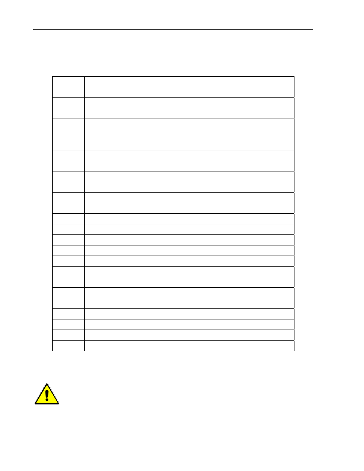
Switch
Position
1 V, 10V or 4-20mA Select 0-5VDC 0-10VDC or 4-20mA
2 I, 10V or 4-20mA Select 0-5VDC 0-10VDC or 4-20mA
3 OVP, 10V Select 0-5VDC 0-10VDC
4 VMON, 10V Select 0-5VDC or 4-20mA 0-10VDC
5 IMON, 10V Select 0-5VDC or 4-20mA 0-10VDC
6
7 LCK-OUT
8 Not Used — —
EXT-OFF, Active-Low
Function OFF (Down) Position ON (Up) Position
Select
Active-High Logic Level Active-Low Logic Level
Enable Front Panel
Controls
Lockout Front Panel
Table 2–1. INTFC SETUP Switch
M51A Option 2-1
Page 14

Isolated Remote Analog Interface Operation DLM 600W Series
2.1.1 INTFC SETUP Switch Functions
The following sections describe the functions of the various switch positions:
V, 10V or 4-20mA Select: Position-1, when ON, selects 0-10VDC programming of the output
voltage. Also, must be set to ON position when the ISOLATED ANALOG INTERFACE
connector is wired for 4-20mA output voltage programming. When OFF, selects 0-5VDC
programming of the output voltage.
I, 10V or 4-20mA Select: Position-2, when ON, selects 0-10VDC programming of the output
current. Also, must be set to ON position when the ISOLATED ANALOG INTERFACE
connector is wired for 4-20mA output current programming. When OFF, selects 0-5VDC
programming of the output current.
OVP, 10V Select: Position-3, when ON, selects 0-10VDC programming of OVP threshold.
When OFF, selects 0-5VDC programming of OVP threshold.
VMON, 10V Select: Position-4, when ON, selects 0-10VDC range for readback of output
voltage. When OFF, selects 0-5VDC readback of output voltage. Also, must be set to OFF
position when the ISOLATED ANALOG INTERFACE connector is wired for 4-20mA output
voltage readback.
IMON, 10V Select: Position-5, when ON, selects 0-10VDC range for readback of output current.
When OFF, selects 0-5VDC readback of output current. Also, must be set to OFF position
when the ISOLATED ANALOG INTERFACE connector is wired for
4-20mA output current readback.
EXT-OFF, Active-Low Select: Position-6, when ON, selects the ACTIVE-LOW logic level for
disabling the output with the EXTERNAL-OFF signal of the ISOLATED ANALOG INTERFACE
connector. When OFF, selects the ACTIVE-HIGH logic level for disabling the output with the
EXTERNAL-OFF signal of the Isolated Analog Interface connector.
LCK-OUT: Position-7, when ON, disables the front panel controls; the front panel
LOCAL(REMOTE) switch will not toggle between the front panel and remote control.
Position-8: Not used
2.2 SETUP Switch
Only two positions of the SETUP switch remain functional: Position-1, REM SNS, for remote
sensing selection; Position-2, SLAVE, for master/slave selection. Their operation is the same
as presented in the Operation Manual. The other switch positions, Position-3 through
Position-8, are not used.
2-2 M51A Option
Page 15
DLM 600W Series Isolated Remote Analog Interface Operation
Figure 2–1. Rear Panel View, Low–Voltage Models
Figure 2–2. Rear Panel View, High–Voltage Models
M51A Option 2-3
Page 16
Isolated Remote Analog Interface Operation DLM 600W Series
2.3 Isolated Analog Interface Connector
The ISOLATED ANALOG INTERFACE connector is a 25-position female
Subminiature-D type.
Pin Function
1 ANALOG-CONTROL input
2 Return for 0-5/10V monitor outputs and EXTERNAL-OFF
3 OVP programming input
4 Voltage monitor output, 4-20mA
5 VOLTAGE-MODE status output
6 Return for 4-20mA monitor outputs, Auxiliary 5VDC, and digital I/O
7 Current monitor output, 0-5/10V
8 1.25VDC output for 4-20mA voltage programming signal
9 Voltage programming input
10 Current programming input
11 1.25VDC output for 4-20mA current programming signal
12 Return for 0-5/10V or resistance programming signals
13 Return for 4-20mA current programming signal
14 EXTERNAL-OFF input
15 Auxiliary 5VDC output (+)
16 OVP resistance programming output, 1mA source
17 OVP status output
18 FAULT status output
19 Voltage monitor output, 0-5/10V
20 1.25V input for 4-20mA voltage programming signal
21 Voltage resistance programming output, 1mA source
22 Current resistance programming output, 1mA source
23 1.25V input for 4-20mA current programming signal
24 Current monitor output, 4-20mA
25 Return for 4-20mA voltage programming
Table 2–2. ISOLATED ANALOG INTERFACE Connector Pinout
CAUTION
The signals of the ISOLATED ANALOG INTERFACE have an internal
connection to chassis ground. Damage could result if the voltage from
signal returns, Pin-2, 6, 12, 13, and 25, to chassis ground exceeds
15VDC.
2-4 M51A Option
Page 17

DLM 600W Series Isolated Remote Analog Interface Operation
2.3.1 ISOLATED ANALOG INTERFACE Functions
The following sections describe the functions of the various signals of the ISOLATED ANALOG
INTERFACE. Pin numbers correspond to the connector pinout of Table 2–2.
Digital Control Input Signals
ANALOG-CONTROL: Pin-1, enables remote analog programming with an active-high logic
level of 3-15VDC. An internal 100kΩ pull-down resistor is provided. When ANALOGCONTROL is asserted, the power supply will power-up with the analog interface in control of the
output voltage. Signal is referenced to Pin-6. Circuit is SELV, and has electrical isolation from
the output of the unit.
EXTERNAL-OFF: Pin-14, disables the output when asserted. Active logic level could be
selected with the INTFC SETUP switch to be high (3-30VDC) or low. An internal 100kΩ pulldown resistor is provided. Signal is referenced to Pin-2. Circuit is SELV, and has electrical
isolation from the output of the unit.
Digital Control Output Signals
VOLTAGE-MODE: Pin-5, nominal 5VDC logic level indicates operation in constant-voltage
mode. Source resistance is 2kΩ. Signal is referenced to Pin-6. Circuit is SELV, and has
electrical isolation from the output of the unit.
OVP: Pin-17, nominal 5VDC logic level indicates that the output has been disabled because of
overvoltage protection. Source resistance is 2kΩ. Signal is referenced to Pin-6. Circuit is
SELV, and has electrical isolation from the output of the unit.
FAULT: Pin-18, nominal 5VDC logic level indicates that the output is disabled because of
overtemperature or summary fault. Source resistance is 2kΩ. Signal is referenced to Pin-6.
Circuit is SELV, and has electrical isolation from the output of the unit.
Analog Monitor Signals
VOLTAGE MONITOR, 0-5/10V: Pin-19, readback of the output voltage is provided with a
0-5VDC or 0-10VDC signal (user selectable with INTFC SETUP switch) indicating
0-100% of full scale output. Signal is referenced to Pin-2. Circuit is SELV, and has electrical
isolation from the output of the unit.
VOLTAGE MONITOR, 4-20mA: Pin-4, readback of the output voltage is provided with a
4-20mA signal indicating 0-100% of full scale output. Signal return for the 4-20mA current is
Pin-6. Circuit is SELV, and has electrical isolation from the output of the unit.
CURRENT MONITOR, 0-5/10V: Pin-7, readback of the output current is provided with a
0-5VDC or 0-10VDC signal (user selectable with INTFC SETUP switch) indicating
0-100% of full scale output. Signal is referenced to Pin-2. Circuit is SELV, and has electrical
isolation from the output of the unit.
CURRENT MONITOR, 4-20mA: Pin-24, readback of the output current is provided with a
4-20mA signal indicating 0-100% of full scale output. Signal return for the 4-20mA current is
Pin-6. Circuit is SELV, and has electrical isolation from the output of the unit.
M51A Option 2-5
Page 18

Isolated Remote Analog Interface Operation DLM 600W Series
Analog Programming Signals
OVP PROGRAMMING INPUT: Pin-3, an input signal of 0-5 volts or 0-10 volts (user selectable
with INTFC SETUP switch) programs the OVP threshold from 5-110% of full scale output
voltage. Signal is referenced to Pin-12. Circuit is SELV, and has electrical isolation from the
output of the unit.
VOLTAGE PROGRAMMING INPUT: Pin-9, an input signal for two methods of programming the
output voltage: 0-5/10V voltage source or 4-20mA current source.
An input signal of 0-5VDC or 0-10VDC (user selectable with INTFC SETUP switch) to Pin-9
programs the output voltage 0-100% of full scale. Signal is referenced to Pin-12.
An input signal of 4-20mA (user selectable with INTFC SETUP switch) to Pin-9 programs the
output voltage 0-100% of full scale. Two jumpers are also required:
Pin-20 to Pin-8; Pin-25 to Pin-12. Signal return for the 4-20mA current is Pin-25; resultant
burden voltage is referenced to Pin-12.
Circuits are SELV, and have electrical isolation from the output of the unit.
CURRENT PROGRAMMING INPUT: Pin-10, an input signal for two methods of programming
the output current: 0-5/10V voltage source or 4-20mA current source.
An input signal of 0-5VDC or 0-10VDC (user selectable with INTFC SETUP switch) to Pin-10
programs the output current 0-100% of full scale. Signal is referenced to Pin-12.
An input signal of 4-20mA (user selectable with INTFC SETUP switch) to Pin-10 programs the
output current 0-100% of full scale. Two jumpers are also required:
Pin-23 to Pin-11; Pin-13 to Pin-12. Signal return for the 4-20mA current is Pin-13; resultant
burden voltage is referenced to Pin-12.
Circuits are SELV, and have electrical isolation from the output of the unit.
OVP RESISTANCE PROGRAMMING OUTPUT: Pin-16 provides a 1mA current source which
would be connected to Pin-3, OVP PROGRAMMING INPUT, with a 0-5kΩ external resistor
connected between Pin-16 to Pin-12, to program the OVP threshold from 5-110% of full scale
output voltage. The INTFC SETUP switch Position-3, OVP, must be set to OFF (down) to
select 0-5VDC input range. Circuit is SELV, and has electrical isolation from the output of the
unit.
VOLTAGE RESISTANCE PROGRAMMING OUTPUT: Pin-21 provides a 1mA current source
which would be connected to Pin-9, VOLTAGE PROGRAMMING INPUT, with a 0-5kΩ external
resistor connected between Pin-21 to Pin-12, to program the output voltage from 0-100% of full
scale output. The INTFC SETUP switch Position-1, V, must be set to OFF (down) to select
0-5VDC input range. Circuit is SELV, and has electrical isolation from the output of the unit.
2-6 M51A Option
Page 19
DLM 600W Series Isolated Remote Analog Interface Operation
CURRENT RESISTANCE PROGRAMMING OUTPUT: Pin-22 provides a 1mA current source
which would be connected to Pin-10, CURRENT PROGRAMMING INPUT, with a 0-5kΩ
external resistor connected between Pin-22 to Pin-12, to program the output current from
0-100% of full scale output. The INTFC SETUP switch Position-2, I, must be set to OFF (down)
to select 0-5VDC input range. Circuit is SELV, and has electrical isolation from the output of the
unit.
Auxiliary Sources
AUXILIARY 5VDC OUTPUT: Pin-15, 5VDC source output for use with logic and programming
circuits. Source capability is adequate to provide for full scale programming of output voltage,
current, or OVP when the user connects it to the appropriate programming input(s). Source is
referenced to Pin-6. Maximum output current is 15mA. Circuit is SELV, and has electrical
isolation from the output of the unit.
AUXILIARY 5VDC RETURN: Pin-6, return of 5VDC AUXILIARY source output. Circuit is
SELV, and has electrical isolation from the output of the unit.
1.25VDC REFERENCE FOR 4-20mA VOLTAGE PROGRAMMING: Pin-20, provides a
1.25VDC reference utilized by internal circuits associated with 4-20mA programming of output
voltage.
1.25VDC REFERENCE FOR 4-20mA CURRENT PROGRAMMING: Pin-11, provides a
1.25VDC reference utilized by internal circuits associated with 4-20mA programming of output
current.
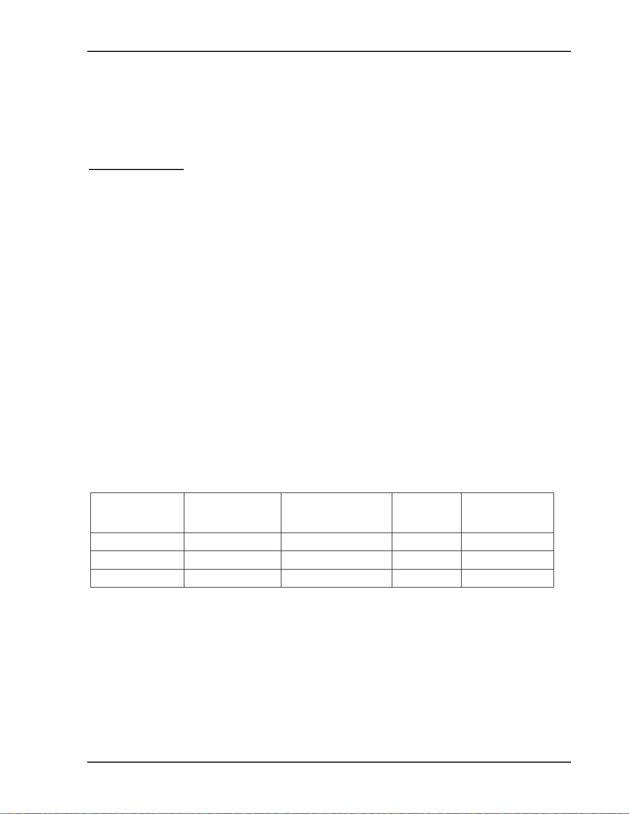
2.4 Remote Programming Configuration
Table 2–3 presents the options for remote control operation. Pin numbers refer to the
ISOLATED ANALOG INTERFACE connector. Switch position numbers refer to the INTFC
SETUP switch on the rear panel.
Mode of
Operation
Remote Only High Level ON (Up) Remote No
Local Only Low or Open Off (Down) Local No
Local/Remote High Level OFF (Down) Remote Yes
ANALOG-
CONTROL
Signal, Pin-1
Table 2–3. Remote Programming Configuration Options
LCK-OUT, INTFC
Setup Switch
Position-7
Power-Up
State
Local/Remote
Toggling
M51A Option 2-7
Page 20

Isolated Remote Analog Interface Operation DLM 600W Series
2.4.1 Voltage Source Programming of Output Voltage
Setting up for voltage source programming of the output voltage is as follows:
1. Set Position-1, V, of the INTFC SETUP switch to OFF (down) for 0-5VDC programming
range.
2. Set Position-1, V, of the INTFC SETUP switch ON (up) for 0-10VDC programming
range.
3. Connect the external programming voltage source to the ISOLATED ANALOG
INTERFACE connector, with positive to Pin-9 and negative to Pin-12.
4. Program the other parameters to the desired limit values: CURRENT PROGRAMMING
INPUT, Pin-10, and the OVP PROGRAMMING INPUT, Pin-3, with respect to pin-12.
5. Connect Pin-1, ANALOG-CONTROL, of the ISOLATED ANALOG INTERFACE
connector to Pin-15.
2.4.2 Voltage Source Programming of Output Current
Setting up for voltage source programming of the output current is as follows:
1. Set Position-2, I, of the INTFC SETUP switch to OFF (down) for 0-5VDC programming
range.
2. Set Position-2, I, of the INTFC SETUP switch ON (up) for 0-10VDC programming range.
3. Connect the external programming voltage source to the ISOLATED ANALOG
INTERFACE connector, with positive to Pin-10 and negative to Pin-12.
4. Program the other parameters to the desired limit values: VOLTAGE PROGRAMMING
INPUT, Pin-10, and the OVP PROGRAMMING INPUT, Pin-3, with respect to pin-12.
5. Connect Pin-1, ANALOG-CONTROL, of the ISOLATED ANALOG INTERFACE
connector to Pin-15.
2.4.3 Voltage Source Programming of OVP
Setting up for voltage source programming of OVP is as follows:
1. Set Position-3, OVP, of the INTFC SETUP switch to OFF (down) for 0-5VDC
programming range.
2. Set Position-3, OVP, of the INTFC SETUP switch ON (up) for 0-10VDC programming
range.
3. Connect the external programming voltage source to the ISOLATED ANALOG
INTERFACE connector, with positive to Pin-3 and negative to Pin-12.
2-8 M51A Option
Page 21

DLM 600W Series Isolated Remote Analog Interface Operation
4. Program the other parameters to the desired limit values: VOLTAGE PROGRAMMING
INPUT, Pin-9, and the CURRENT PROGRAMMING INPUT, Pin-10, with respect to
Pin-12.
5. Connect Pin-1, ANALOG-CONTROL, of the ISOLATED ANALOG INTERFACE
connector to Pin-15.
2.4.4 Resistance Programming of Output Voltage
Setting up for resistance programming of the output voltage is as follows:
1. Set Position-1, V, of the INTFC SETUP switch to OFF (down) for 0-5VDC programming
range.
2. Connect the external programming resistance, 0-5kΩ, to the ISOLATED ANALOG
INTERFACE connector, from Pin-21 to Pin-12.
3. Connect a jumper from Pin-21 to Pin-9.
4. Program the other parameters to the desired limit values: CURRENT PROGRAMMING
INPUT, Pin-10, and the OVP PROGRAMMING INPUT, Pin-3, with respect to Pin-12.
5. Connect Pin-1, ANALOG-CONTROL, of the ISOLATED ANALOG INTERFACE
connector to Pin-15.
2.4.5 Resistance Programming of Output Current
Setting up for resistance programming of the output current is as follows:
1. Set Position-2, I, of the INTFC SETUP switch to OFF (down) for 0-5VDC programming
range.
2. Connect the external programming resistance, 0-5kΩ, to the ISOLATED ANALOG
INTERFACE connector, from Pin-22 to Pin-12.
3. Connect a jumper from Pin-22 to Pin-10.
4. Program the other parameters to the desired limit values: VOLTAGE PROGRAMMING
INPUT, Pin-9, and the OVP PROGRAMMING INPUT, Pin-3, with respect to Pin-12.
5. Connect Pin-1, ANALOG-CONTROL, of the ISOLATED ANALOG INTERFACE
connector to Pin-15.
M51A Option 2-9
Page 22

Isolated Remote Analog Interface Operation DLM 600W Series
2.4.6 Resistance Programming of OVP
Setting up for resistance programming OVP is as follows:
1. Set Position-3, OVP, of the INTFC SETUP switch to OFF (down) for 0-5VDC
programming range.
2. Connect the external programming resistance, 0-5kΩ, to the ISOLATED ANALOG
INTERFACE connector, from Pin-16 to Pin-12.
3. Connect a jumper from Pin-16 to Pin-3.
4. Program the other parameters to the desired limit values: VOLTAGE PROGRAMMING
INPUT, Pin-9, and the CURRENT PROGRAMMING INPUT, Pin-10, with respect to pin-
12.
5. Connect Pin-1, ANALOG-CONTROL, of the ISOLATED ANALOG INTERFACE
connector to Pin-15.
2.4.7 4-20mA Current Source Programming of Output Voltage
Setting up for 4-20mA programming of the output voltage is as follows:
1. Set Position-1, V, of the INTFC SETUP switch to OFF (down) for 0-5VDC programming
range.
2. Connect the external 4-20mA programming current source to the ISOLATED ANALOG
INTERFACE connector, with source at Pin-9 and return at Pin-25.
3. Connect a jumper from Pin-25 to Pin-12.
4. Connect a jumper from Pin-8 to Pin-20.
5. Program the other parameters to the desired limit values: CURRENT PROGRAMMING
INPUT, Pin-10, and the OVP PROGRAMMING INPUT, Pin-3, with respect to pin-12.
6. Connect Pin-1, ANALOG-CONTROL, of the ISOLATED ANALOG INTERFACE
connector to Pin-15.
2.4.8 4-20mA Current Source Programming of Output Current
Setting up for 4-20mA programming of the output current is as follows:
1. Set Position-2, I, of the INTFC SETUP switch to OFF (down) for 0-5VDC programming
range.
2. Connect the external 4-20mA programming current source to the ISOLATED ANALOG
INTERFACE connector, with source at Pin-10 and return at Pin-13.
2-10 M51A Option
Page 23
DLM 600W Series Isolated Remote Analog Interface Operation
3. Connect a jumper from Pin-13 to Pin-12.
4. Connect a jumper from Pin-11 to Pin-23.
5. Program the other parameters to the desired limit values: VOLTAGE PROGRAMMING
INPUT, Pin-9, and the OVP PROGRAMMING INPUT, Pin-3, with respect to pin-12.
6. Connect Pin-1, ANALOG-CONTROL, of the ISOLATED ANALOG INTERFACE
connector to Pin-15.
2.5 EXTERNAL-OFF Control
The EXTERNAL-OFF control input provides the same functionality as the OUTPUT switch on
the front panel. When asserted, it will turn off the output converter, discharge the output
capacitors with the downprogrammer, and reset the OVP and FAULT monitors. The signal
could be configured to be either active-low or active-high with the INTFC SETUP switch on the
rear panel.
Set Position-6, /EXT-OFF, to the OFF (down) position to select the active-high logic level for
asserting EXTERNAL-OFF. Set Position-6, /EXT-OFF, to the ON (up) position to select the
active-low logic level for asserting EXTERNAL-OFF. The logic-high level could be produced
with a voltage source within the range of 3-30VDC, and would be connected to Pin14, positive,
and Pin-2, return. The circuit is SELV, and has electrical isolation from the output of the unit.
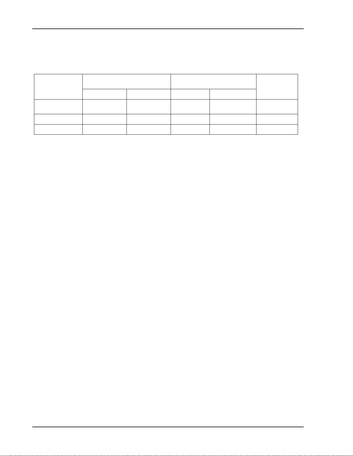
2.6 Remote Monitoring
Analog signals are available for monitoring the output voltage and current. These signals vary
proportionally to the output parameters, and have user selectable ranges of 0-5VDC, 0-10VDC,
or 4-20mA for an output change from zero to full scale. Refer to Table 2–4 for information on
configuring the monitors.
Output
Monitor
Signal
Voltage Pin-19 Pin-2 4, VMON OFF (down) 0-5VDC
Voltage Pin-19 Pin-2 4, VMON ON (up) 0-10VDC
Voltage Pin-4 Pin-6 4, VMON OFF (down) 4-20mA
Current Pin-7 Pin-2 5, IMON OFF (down) 0-5VDC
Current Pin-7 Pin-2 5, IMON ON (up) 0-10VDC
Current Pin-24 Pin-6 5, IMON OFF (down) 4-20mA
ISOLATED ANALOG
INTERFACE Connections
Signal Return Position Setting
Table 2–4. Remote Monitoring
INTFC SETUP Switch
Signal
Range
M51A Option 2-11
Page 24
Isolated Remote Analog Interface Operation DLM 600W Series
2.7 Remote Digital Status Signals
Digital signals are available for remote monitoring the operational status of the unit. Refer to
Table 2–5 for information on the characteristics of the signals.
Status
Indicator
Signal
VOLTAGE-
MODE
OVP Pin-17 Pin-6 5V 0V 2kΩ
FAULT Pin-18 Pin-6 5V 0V 2kΩ
ISOLATED ANALOG
INTERFACE Connections
Signal Return Asserted Not Asserted
Pin-5 Pin-6 5V 0V 2kΩ
Table 2–5. Remote Digital Status Signals
Logic Levels (with No
Signal Output Current)
Output
Resistance
2-12 M51A Option
 Loading...