

Page 1
Part No. NC003198
September 2011
DFX II Series
Digital Force Gauge
User Manual
- 1 -
Page 2
Icons
WARnInG
The raised hand icon warns of a situation or condition that may lead to personal injury
or death. Do not proceed until the warning is read and thoroughly understood.
Warning messages are shown in bold type.
DAnGERoUs VoLTAGE
The lightning icon warns of the presence of an uninsulated dangerous voltage within
the product enclosure that might be of sufcient magnitude to cause serious shocks
or death. Never open the enclosures unless you are an authorized and qualied
Chatillon® service personnel. Never open any enclosure when power is connected to
the system or its components.
cAUTIon
The exclamation point icon indicates a situation or condition that may lead to equipment malfunction or damage. Do not proceed until the caution message is read and
thoroughly understood. Caution messages are shown in bold type.
noTE
The note icon indicates additional or supplementary information about the action,
activity or concept. Notes are shown in bold type.
cAUTIon
HIGH FoRcEs ARE oFTEn InVoLVED WITH THE
MATERIAL TEsTInG PRocEssEs.
THE PRoDUcT Is noRMALLY UsED UnDER BATTERY PoWER. HoWEVER, MAIns PoWER MAY BE
UsED.
IF THE EQUIPMEnT Is UsED In A MAnoR noT
sPEcIFIED BY THE MAnUFAcTURER, THE
PRoTEcTIon PRoVIDED BY THE EQUIPMEnT MAY
BE IMPAIRED.
To MAInTAIn ALL AsPEcTs oF THE sPEcIFIcATIon,
onLY AMETEK® APPRoVED AccEssoRIEs,
connEcTIons AnD coMPonEnTs sHoULD BE
UsED.
sTRIcTLY ADHERE To ALL sPEcIFIED sAFETY
PRocEDUREs
READ THIs MAnUAL BEFoRE UsInG THIs PRoDUcT.
Features
ESD Considerations: The DFX II force
gauge may turn OFF if a high voltage ESD
discharge occurs to the output shaft. In
the unlikely event that a high voltage discharge
occurs, please turn back ON the DFX II force gauge
and it will operate normally.
When designing custom fixtures ensure
the load rating of the custom fixtures
exceed the load rating of the load cell in
the force gauge being used. i.e. If the load cell is
rated for 100 LBF the custom fixtures should have
a load rating greater than 100 LBF.
The DFX II Series have the following standard
features:
l +0.3% of Full Scale Accuracy
l Large, Easy-to-Read LCD Display
l Selectable Units (ozf, gf, lbf, kgf, N)
l Lockable Units
l Normal and Peak Measurement Modes
l Selectable Languages (English, French, Spanish,
Portuguese, German, Chinese)
l Automatic Power Save Shutdown
l Battery Operation 70 to 100-hours of
continuous use
l Universal Battery Charger
l Internal Calibration Procedure
- 2 -
Page 3
Introduction
The Chatillon
®
DFX II Series digital force gauges is a battery-operated force indicator. It uses a NiMH bat-
tery for power. It may also be used with the DFX II battery charger/charger (included) supplied.
The DFX II Series may be used to measure and display tensile or compressive loads at an accuracy of +0.3%
of full scale. The DFX II Series may also be set to capture the peak tensile or compressive load. The DFX Series
is available in four models having four different capacities and user-selectable units of measurement.
Model ozf gf lbf kgf N
DFX2-010 160 x 0.2 5000 x 5 10 x 0.01 5 x 0.005 50 x 0.05
DFX2-050 800 x 1 25000 x 20 50 x 0.05 25 x 0.02 250 x 0.2
DFX2-100 1600 x 2 50000 x 50 100 x 0.1 50 x 0.05 500 x 0.5
DFX2-200 - - 200 x 0.2 100 x 0.1 1000 x 1
The gauge may be setup to display text in English, French, German, Spanish, Portuguese and Chinese.
Conformance
The Chatillon DFX II Series has been assessed against the essential health and safety requirements of the
Low Voltage and the EMC Directives listed and found to be in compliance.
BS EN 61010-1:2001 Safety Requirement for Electrical Equipment
BS EN 61000-6-3:2001 EMC Generic Emission Standard
BS EN 61000-6-1:2001 EMC Generic Immunity Standard
The DFX II Series is a RoHS and WEEE compliant device.
Packaging
The Chatillon DFX II Series is supplied with the
following standard accessories:
l Flat Adapter, 100 lbf (p/n SPK-FMG-011A) or
l Flat Adapter, 200 lbf (p/n SPK-FMG-011B)
l Hook Adapter, 50 lbf (p/n SPK-FMG-012A) or
l Hook Adapter, 100 lbf (p/n SPK-FMG-012B) or
l Hook Adapter, 200 lbf (p/n SPK-FMG-012C)
l DFX II Universal Battery Charger/Charger
(p/n charger SPK-DF2-UNIV)
l DFX II Carrying Case (SPK-DF-118)
l Certificate of Conformance
Optional Certificate of Calibration with Data is available.
The DFX II is supplied with one (1) flat adapter and (1)
hook. The accessory supplied is dependent on the DFX
II capacity.
- 3 -
Page 4
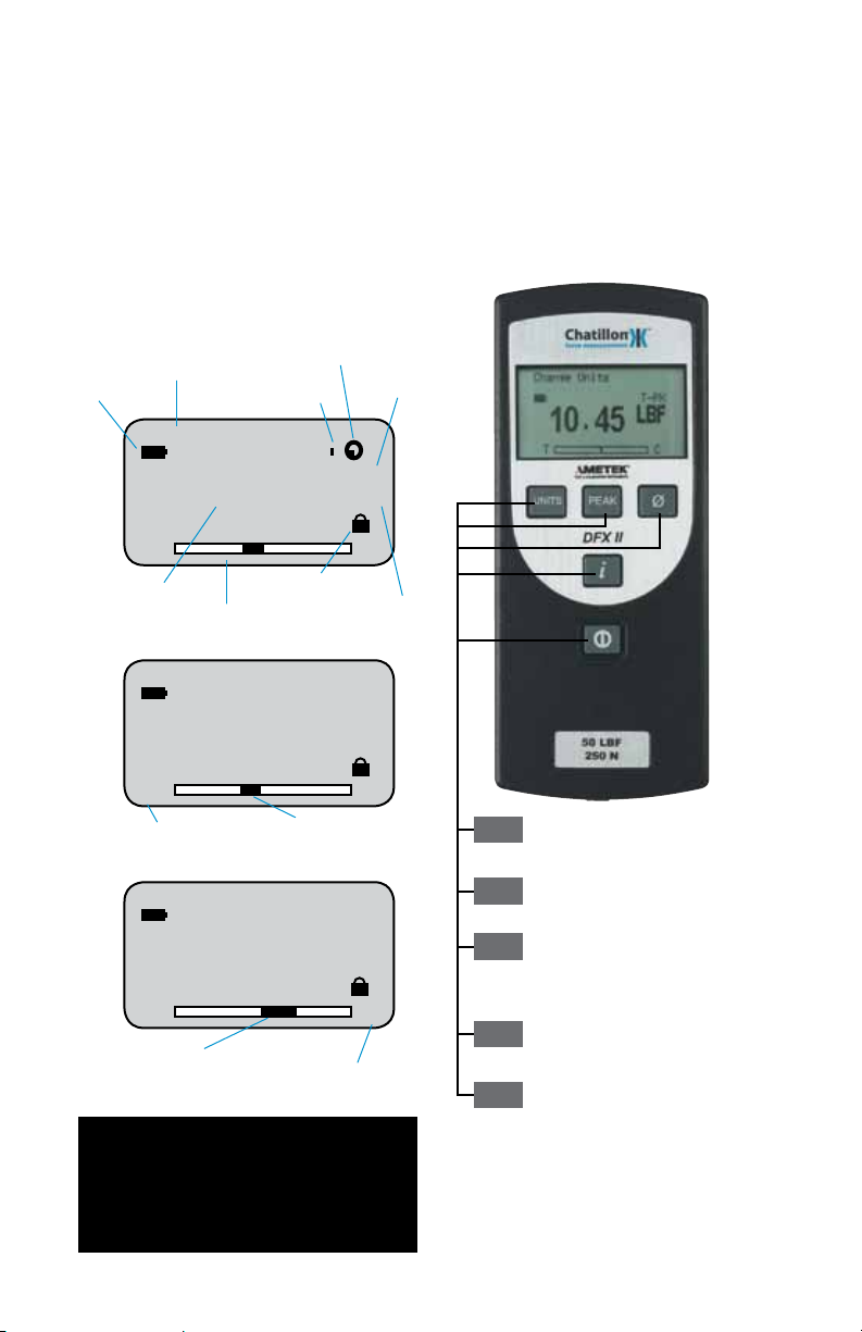
Display Layout
The Chatillon DFX II Series has a high resolution,
dot-matrix LCD, 8 lines, 21 characters. Display
contrast is set at the factory and requires no adjustment. The load bargraph, at the bottom of the
display, indicates the load currently being applied
to the internal load sensor. The bargraph fills from
the center location with tensile loads measured to
the left and compression loads measured to the
right. A load direction indicators shows whether
the applied load is tensile or compressive.
Message Prompt
Battery Status
Auto Shutdown feature is ON
Peak Filter is ON
Mode indicator
Keypad
The Chatillon DFX Series has a rubber keypad
containing the following keys:
l On/Off Key
l UNITS Key
l PEAK Key
l ZERO Key
l INFO Key
Change Mode
q
T
q
Measured result
Measured load bargraph
q
T
q
Tensile load indicator
11.23
T
Compression load applied to sensor
1.23
Units Lock feature is ON
1.23
Tensile load applied to sensor
Compression load indicator
q
Norm
LBF
C
Units of measurement
Norm
LBF
C
Norm
LBF
q
q
C
Changes measurement units: ozf, gf, lbf, kgf,
Units
N. May be disabled so that units cannot be
changed. (See Units Lock Feature).
Select to view/capture peak measurements.
Peak
Change between Normal and Peak.
Select to Zero measurement or to Tare up to
Ø
10% of the gauge’s capacity.
Note: When in INFO mode, select the Zero key
to exit and return to Home.
Select to view gauge information and to select
i
gauge operating options. (See Using INFO Key).
Turn Gauge On or Off.
Note
The bargraph fills from the center and load direction
indicator appears when load is being applied to the
internal load sensor.
- 4 -
Page 5
Selecting Mode
The DFX II Series has three measurement modes:
Normal, Tension Peak (T-PK) and Compression
Peak (C-PK). Select the Peak key to display the
peak load measured in tension or compression.
Use the zero key to clear the peak reading and to
prepare the gauge for the succeeding measurement.
Change Mode
View Peak Result
The Chatillon DFX II Series will display the peak
(maximum) load achieved for a test. There are
two methods to view peak results:
1. Place gauge in Normal mode. Apply a push
or pull force against the load sensor. Select the
PEAK key. View the peak result.
Norm
1.23
T
Peak
Change Mode
1.23
q
T
q
Peak
Change Mode
1.23
T
Peak
Zero and Taring
The DFX II Series has a dedicated Zero key for
zeroing results or taring. You may tare out up to
10% of the DFX II gauge’s rated capacity. Select
the Zero key to zero or tare.
0.0
LBF
C
T-PK
LBF
C
C-PK
LBF
C
C-PK
LBF
q
q
2. Place gauge in Peak mode by selecting the
PEAK key before performing the test. Apply a
push or pull force against the load sensor. View
the peak result.
Norm
1.23
q
T
q
Peak
4.56
q
T
q
Peak
7.89
T
Peak
Note
The corresponding load direction indicator appears
when viewing a peak load result or when load is
being applied to the internal load sensor.
LBF
C
T-PK
LBF
C
C-PK
LBF
C
q
q
T
C
Ø
- 5 -
Page 6
Using the INFO Key
The INFO (information) key is used to display the
gauge’s characteristics such as firmware revision.
It is also used to view Overloads and to set the
Units Lock feature.
Depressing the INFO key cycles the firmware
through the following functions:
1. Capacity
2. Firmware Revision
3. Overload History
4. Battery Life
5. Automatic Shutoff
6. Units Lock
7. Display Language
Note
When in INFO mode, you may exit at any time by pressing
the ZERO key.
View Capacity
The DFX II Series displays its capacity x resolution.
To view the DFX II gauge’s capacity characteristics, perform the following key sequence:
1. INFO <Capacity>
Capacity
200 x 0.2 lbf
100 x 0.1 kgf
1000 x 1 N
T
C
i
View Firmware
The DFX II Series displays its firmware information. To view the firmware characteristics, perform
the following key sequence:
1. INFO <Capacity>
2. INFO <Firmware>
Firmware
Model DFX-200
E91.99
Rev. No. V1.00
Rev. Date dd/mm/yy
T
C
i
View Overloads
The DFX II Series displays its Overload History.
To view the overloads, perform the following key
sequence:
1. INFO <Capacity>
2. INFO <Firmware>
3. INFO <Overload>
Overload
No. of Overloads
No. of Tension 0
No. of Comp. 0
T
C
i
IMPORTANT
Overloads can damage the load sensor. Always take
special care to observe the bargraph to ensure that the
- 6 -
I
sensor is not being overloaded.
Page 7
View Battery Life
The DFX II Series displays its battery life. The DFX
II uses a rechargeable NiMH battery cell. To view
the DFX II battery life, perform the following key
sequence:
1. INFO <Capacity>
2. INFO <Firmware>
3. INFO <Overload>
4. INFO <Battery>
Battery
Est Battery Life
T
100 hrs
9.00 Volts
C
i
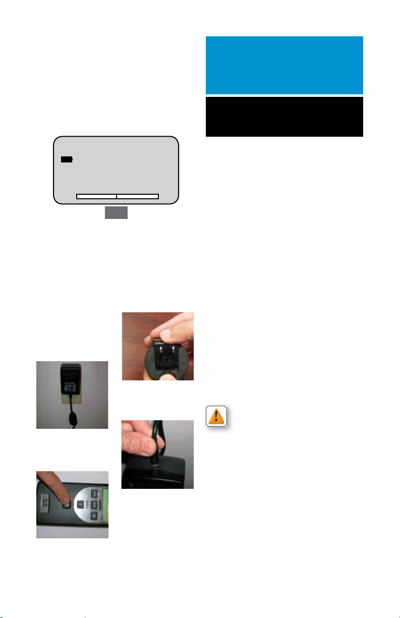
Using The Battery Charger
The DFX II Series may be battery operated or operated
using the battery charger accessory (SPK-DF2-UNIV).
When the battery charger is used, the internal batteries
are charged. The battery charger may be plugged into a
115V or 230V source power outlet. The battery charger
contains three interchangeable plug styles: USA, EURO
and UK.
1. Place the correct plug onto the
battery charger.
1
Use the Chatillon Battery Charger that comes with
IMPORTANT
the DFX II Series digital force gauge.
Do NOT use generic battery chargers. These can
permanently damage the gauge electronics.
Note
The DFX II will display “Recharge Battery” when the
battery voltage drops to approximately 4.5VDC
To charge the DFX force gauge plug the phone jack
of the supplied universal battery charger into the DFX
force gauge then plug the battery charger into the
correct AC power outlet. Ensure the correct power is
applied to the battery charger. Never plug the USA
2-prong 115VAC charger into a 230VAC power source.
To obtain a full charge it is recommended the DFX force
gauge is charged for 15-20 hours. The DFX force gauge
should get approximately 70 to 100 hours of battery life
on a single charge.
A battery icon appears on the main operating display
and operates like a bar graph. When the gauge has a
full charge, the battery icon appears full. As the battery
voltage diminishes, the battery icon will start to empty.
You may view the estimated battery life based on current usage in hours by depressing the “i” key until the
battery life screen appears.
2
3. Plug the battery charger into
the DFX II power input.
4
2. Plug the battery charger into the
source power outlet.
4. Press the DFX II On/Off key to
turn power ON.
The DFX force gauge will alert you when the battery
assembly needs to be recharged by adding a message
to the main test screen “Recharge Battery”. The force
gauge will shutdown automatically if the battery voltage
reaches approximately 4.5VDC.
CAUTION: Do not attempt to charge the
Chatillon DFX series force gauge with any
other charger than the one supplied with
the force gauge or supplied by an authorized
Chatillon dealer. The nickel metal hydride batteries are
3
temperature sensitive and the battery charger is specifically design to properly charge this battery assembly
without damaging it.
- 7 -
Page 8
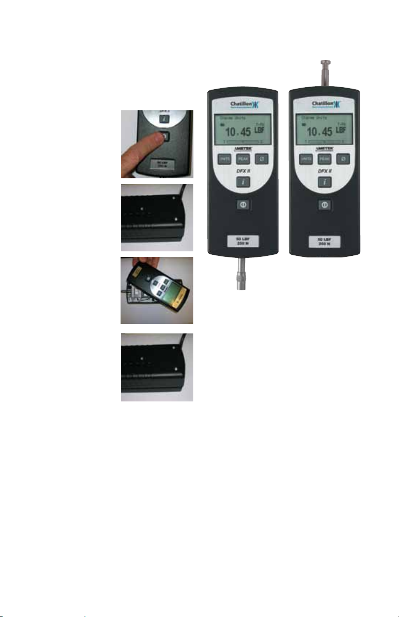
Reversing the Housing
The DFX II Series comes from the factory with
the measuring shaft located at the bottom of the
gauge when reading the display.
In applications where the measuring shaft is required to be at the top of the gauge, simply reverse
the housing.
1. Turn power to the gauge OFF.
2. Remove two (2) 6/32 screws on
the gauge housing using Hex key
supplied with the DFX II.
3. Rotate the top housing 180-degrees being careful not to strain or
damage the internal wiring.
DFX II gauges shown with top housing reversed.
4. Re-assemble gauge housing
using two #6-32 hex screws.
- 8 -
Page 9

Auto Shutdown Feature
The DFX II Series has an option to automatically
shut off power when the gauge is not being used
during a 30 minute period, e.g. no key presses.
To enable the Auto Shutdown feature, follow this
setup procedure and depress the following keys:
Selecting Units
The DFX II Series has a dedicated Units key. Select
to display results in different units of measure.
DFX II-010, DFX II-050 and DFX II-100 models may
display units as ozf, gf, lbf, kgf or N.
1. INFO <Capacity>
2. INFO <Firmware>
3. INFO <Overload>
4. INFO <Battery>
5. INFO <Auto Shutdown>
When the Auto Shutdown is ON, the gauge power
will automatically be turned OFF after 30 minutes
of inactivity, e.g. no key presses. This helps save
battery life.
Auto Shutdown
Auto Shutdown Status
OFF
PEAK to Change
INFO to Proceed
T
Peak
Auto Shutdown
Auto Shutdown Status
ON
PEAK to Change
INFO to Proceed
T
Peak
C
C
The DFX II -200 will display lbf, kgf or N only.
The Units key may be disabled so that the Units
cannot be changed by the operator. See Units Lock
Feature.
Change Units
Norm
1.23
T
Units
Change Units
1.23
T
Units
Change Units
1.23
T
Units
OZF
C
Norm
GF
C
Norm
LBF
C
Automatic Shutdown Indicator when On.
Norm
1.23
T
Note
The DFX II will shutdown, when the battery voltage
is at approximately 4.5Vdc.
Replace batteries or use charger accessory.
OZF
C
- 9 -
Change Units
T
Units
Change Units
T
1.23
1.23
Norm
KGF
C
Norm
N
C
Page 10

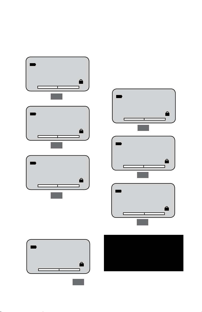
Units Lock Feature
The DFX II Series has an option to “lock the units”.
This prevents the operator from changing the units
of measure and disables the UNITS key.
To enable the Units Lock feature, follow this setup
procedure and depress the following keys:
1. INFO <Capacity>
2. INFO <Firmware>
3. INFO <Overload>
4. INFO <Battery>
5. INFO <Auto Shutdown>
6. INFO <Units Lock>
Units Lock
Units Lock Status
OFF
PEAK to Change
INFO to Proceed
T
Peak
Units Lock
Units Lock Status
ON
PEAK to Change
INFO to Proceed
T
Peak
C
C
1.23
q
T
q
Shown: Units Lock feature is ON.
1.23
q
T
q
Shown: Units Lock feature is OFF.
Norm
LBF
C
Norm
LBF
C
Units Locked
Norm
1.23
q
T
q
Units
The Units Locked icon appears when this option is
ON. Pressing the UNITS key will not change
the units of measurement.
Note
LBF
C
- 10 -
Page 11

Selecting Language
The DFX II Series allows users to select their display
language. Textual information can be displayed in
the following languages: English, Spanish, French,
Portuguese, Chinese and German. To select your
display language, follow this setup procedure and
depress the following keys:
1. INFO <Capacity>
2. INFO <Firmware>
3. INFO <Overload>
4. INFO <Battery>
5. INFO <Auto Shutdown>
6. INFO <Units Lock>
7. INFO <Language>
Language
ENGLISH
PEAK to Change
INFO to Proceed
T
Lenguaje
ESPANOL
PEAK para cambio
INFO para proceder
T
Langue
FRANCAIS
PEAK pour changer
INFO pour realiser
T
Idioma
Peak
Peak
Peak
Sprachauswahl
DEUTSCH
PEAK zum wechseln
INFO zum fortfahren
C
q
T
T
q
C
Peak
C
C
PORTUGUES
PEAK para mudar
INFO para continuar
T
Peak
C
- 11 -
Page 12

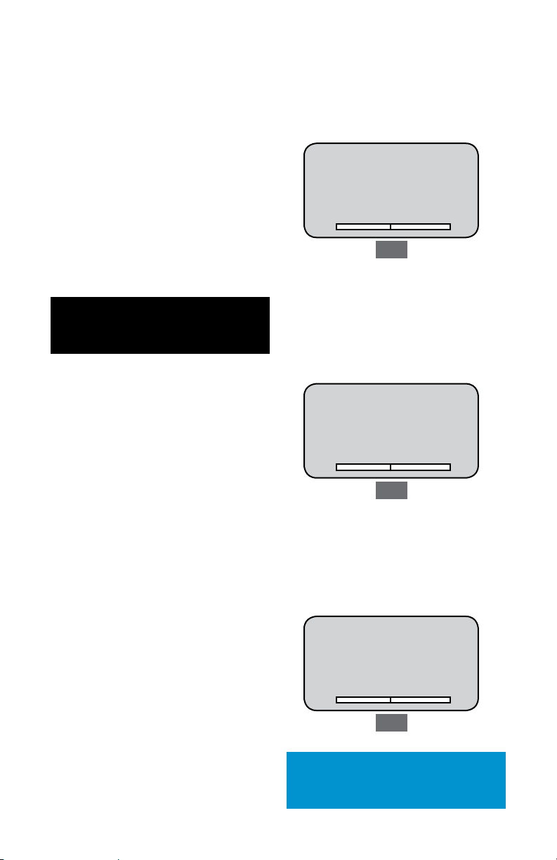
Enabling Peak Filter
The DFX II Series has a Peak Filter option that
controls the sampling rate of the gauge.
The DFX II is shipped from the factory with the Peak
Filter ON. An icon on the display indicates when the
Peak Filter is ON.
When the Peak Filter is set to ON the Peak Capture
is 40Hz. When it is set to OFF the Peak Capture is
1000Hz.
To change the Filter (Sample Rate) for your DFX II,
follow this setup procedure and depress the following keys:
1. INFO <Capacity>
2. INFO <Firmware>
3. INFO <Overload>
4. INFO <Battery>
5. INFO <Auto Shutdown>
6. INFO <Units Lock>
7. IINFO <Language>
8. INFO <Filters>
Peak Filter
Peak Filter Status
PEAK to Change
INFO to Proceed
T
ON
C
Peak
Filter
Peak Filter Status
PEAK to Change
INFO to Proceed
T
OFF
C
Peak
- 12 -
Page 13

Affixing Adapters & Fixtures
The DFX II Series has a threaded load sensor shaft.
It accepts threaded adapters, grips or fixtures
directly. Couplers may be used to adapt to different
thread sizes.
The DFX2-010, DFX2-050 and DFX2-100 models
have a #10-32 male threaded load sensor shaft.
The DFX2-200 has a 5/16-18 male threaded load
sensor shaft.
Be careful to not over tighten adapters as this
can damage the load sensor. Adapters should be
torqued to 5 in-lbs (45 N-m).
Using Handle Assemblies
The DFX II Series may be used with the optional
handle assembly (p/n SPK-DF-HANDLE) or pistol
grip (p/n SPK-FMG-141).
(p/n SPK-DF-HANDLE)
(p/n SPK-FMG-141)
- 13 -
Page 14

Accessories
SPK-FMG-008A (#10-32)
Chisel Points
SPK-FMG-009B (5/16-18)
Points
SPK-FMG-008B (5/16-18)
SPK-FMG-009A (#10-32)
NC000721 (5/16-18)
NC000725 (5/16-18)
Hooks, Stationary
ML3868 (5/16-18)
Hooks, Swivel
17057 (#10-32 to 1/4-20)
SPK-FMG-012C (5/16-18)
SPK-FMG-012B (#10-32)
SPK-FMG-012A (#10-32)
ML3869 (5/16-18)
ML3850 (#10-32)
ML3867 (#10-32)
17056 (1/4-20 to 5/16-18)
SPK-FMG-010B (5/16-18)
Notches
17160 (#10-32 to #10-32)
13048 (1/4-28 to 5/16-18)
SPK-FMG-010A (#10-32)
Couplers
SPK-FMG-013B (5/16-18)
SPK-FMG-013A (#10-32)
Extension Rods
- 14 -
Page 15

Mounting Your DFX II
to a Chatillon Tester
The DFX II Series may be used with a Chatillon
mechanical or motorized force tester. The chart
shows the Gauge Adapter Plate that may be
required to fit the gauge to the tester.
Test Model Adapter Part No.
MT150 SPK-MT-0001
MT500 SPK-MT-0004
LTCM-100 Not Required
LTCM-500 Not Required
TT NC002582
These adapters are especially designed to ensure
Note
gauge/tester centerline alignment.
SPK-MT-0001
SPK-MT-0004
Shown: The DFX II attached to the MT150 crdigital force
gauge used with the Chatillon MT150 tester. attached
to the MT150 crosshead using the SPK-MT-0001 kit
(top right)
NC002582
- 15 -
Page 16

DFX II Series Calibration
IMPORTANT
Gauge calibration should be performed only by those properly trained to service and calibrate Chatillon instruments. Factory service and calibration is available on these instruments and traceable Certificates of Calibration are provided as requested. Visit www.chatillon.com for a listing of authorized
Distributors.
Any changes made to the gauge using the calibration procedure voids the Certificate of Calibration
that accompanied your DFX II Series force gauge. Customers electing to calibrate their gauge do so
at their risk and with the understanding that they are effecting the performance of the gauge.
The Calibration Procedure described in the following pages will permit a user to calibrate and
re-characterize the loadcell being used. Exercise extreme caution when calibrating any precision
instrument.
IMPORTANT
The sensor used in your DFX II Series gauge is temperature sensitive. The gauge should be turned
ON and allowed to acclimate to ambient temperature before normal use and before being calibrated.
A 7 minute “warm-up” period is recommended.
Calibration Setup
A hanger must be used when calibrating the DFX
II Series digital force gauge in compression mode.
The hanger will ensure that side loading effects are
eliminated. Stacking deadweights onto a platen to
perform a compression calibration is NOT acceptable.
Shown: a correct compression calibration setup using a
hanger fixture.
- 16 -
Page 17

Procedure
The Chatillon DFX II Series is supplied with a Certificate of Conformance. The gauge was tested and
found to have a measurement accuracy of 0.5% of
full scale or better.
Calibration Procedure
The DFX II Series calibration procedure is contained
in the gauge firmware. The calibration is a four
point calibration: full scale compression, zero compression, full scale tension, zero tension.
Select CALIB Units
UNITS to change
INFO to proceed
PEAK to go back
T
0.0
i
LBF
C
To access the calibration routine, begin with the
gauge power OFF.
Press the ON key. While the “Chatillon Logo” is
displayed, press PEAK then UNITS.
Model DFX II-100
Rev. No. V1.00
Rev. Date dd/mm/yy
Chatillon
T
Units
Gauge Service
PEAK to calibrate
UNITS to diagnostics
INFO to exit
T
Select Gauge Model
DFX II-100
UNITS to change
INFO to proceed
PEAK to exit
T
Peak
Peak
Peak
C
C
C
Note: The units of measure selected must correspond to
the weights that are being used for the calibration.
Place gauge in
horizontal position
INFO to proceed
PEAK to go back
T
Note: Placing the gauge horizontally means to lay the
gauge perfectly flat on its backside making sure no load
is being applied to the loadcell shaft.
Place gauge in
compression mode and
exercise 3 times
INFO to proceed
PEAK to go back
T
Note: You must use a hanger when performing the
compression calibration routine to eliminate side load
effects on the loadcell.
0.0
i
0.0
i
LBF
C
LBF
C
q
q
Selecting PEAK during the calibration procedure
will take you back to the last step in the procedure.
- 17 -
Note
Page 18

DFX II Series Calibration
Remove all weight, but
leave compression
fixture attached
INFO to proceed
PEAK to go back
T
0.0
LBF
C
i i
Note: Remove all weights but leave compression
calibration hanger attached to the force gauge.
Add full scale
compression load
100 lbf
INFO to proceed
PEAK to go back
T
00.0
LBF
C
q
q
i i
Note: Carefully add weights equal to the DFX II gauge’s
full scale capacity to the hanger fixture.
Remove full scale
load for zero
verification
INFO to proceed
PEAK to go back
100.0
T
LBF
C
q
q
i i
Place gauge in
tension mode and
exercise 3 times
INFO to proceed
PEAK to go back
q
q
Note: Exercise the loadcell three times by pulling on the
loadcell shaft.
Remove all weight, but
leave tension
fixture attached
INFO to proceed
PEAK to go back
Add full scale
tension load
100 LBF
INFO to proceed
PEAK to go back
q
q
100.0
T
T
100.0
T
0.0
LBF
C
LBF
C
LBF
C
Verify compression
calibration
0.0
INFO to proceed
PEAK to go back
T
LBF
C
q
q
i
Note: Verify the compression calibration by checking
both the full scale (span) and zero. When no load is
applied, the display should read zero. When full scale
weights are applied to the fixture, the display should
read the full scale weight equivalent.
Note: Carefully add weights equal to the DFX II gauge’s
full scale capacity to the hanger fixture.
Note
Selecting PEAK during the calibration procedure will
take you back to the last step in the procedure.
- 18 -
Page 19

Remove full scale
load for zero
verification
INFO to proceed
PEAK to go back
T
0.0
LBF
Save new calibration
0.0
INFO to proceed
PEAK to go back
C
T
LBF
C
i
Note: Remove all weights but leave tension fixture attached to the force gauge.
Verify tension
calibration
INFO to proceed
PEAK to go back
q
q
100.0
T
LBF
C
i
Note: Verify the tension calibration by checking both the
full scale (span) and zero. When no load is applied, the
display should read zero. When full scale weights are
applied to the fixture, the display should read the full
scale weight equivalent.
i
Note: Select INFO to save the calibration.
- 19 -
Page 20

Performing a Tensile Test
The Chatillon DFX II Series may be used to perform
a tensile test (also called a pull test). A tensile
test causes a pulling effect on the load sensor
shaft. The shaft is commonly equipped with a hook
adapter or some form of grasping fixture.
Normal Mode Test
Place the gauge into Normal mode by pressing the
PEAK key until the mode indicator about the units
of measure reads NORM. Normal mode means the
gauge will display the real-time load applied to the
load sensor shaft. The peak or maximum load is not
displayed in Normal mode.
Affix your tensile test adapter (hook, grasping
fixture, or the like).
Press the Zero key to zero or tare out the weight of
the adapter or fixture attached to the load sensor
shaft.
1
Select Normal Mode
Place the DFX II in Normal
mode by pressing the PEAK
key until “NORM” is displayed
above the units indicator.
Select Units of
Measure
Select the UNITS key to specify
the units of measure you want
displayed.
Affix Test Adapter
Affix your testing adapter to
the DFX II load sensor shaft.
“Finger-tight” the adapter to
the #10-32 threaded shaft.
2
Press the UNITS key to setup your DFX II to display
load in your required units of measurement.
Apply a pull force to the load sensor shaft by pulling
on the sample under tester.
In a handheld test, make sure to keep the gauge
perpendicular to the centerline of the test sample
to avoid side loading effects, e.g. where load is not
being applied linearly through the load sensor shaft.
In a tester application, where the gauge is mounted
to a test stand, ensure that the center line of the
load sensor shaft is aligned directly with the sample
on the tester.
Observe the load bargraph on the DFX II gauge
to guard against overloads. If the bargraph approached being completely filled, stop the test
immediately to avoid an overload.
While you are pulling the sample, the tensile load
indicator will display (opposing arrows).
Once the test is completed, press the PEAK key
to observe the maximum tensile load that was
achieved during your test.
Peak Tensile Test (T-PK)
This test is performed identically to the Normal
Mode Test except the gauge is placed in PEAK
mode. Placing the gauge in PEAK mode automatically “freezes and displays” the maximum load
achieved during your test.
3
Apply Pull Force
Apply a pulling force to the
sample under test. Observe
the load bargraph (fills from
the center towards the “T”)
and the Tensile Load Indicator
(arrows). The main display will
indicate the load being applied
to the load sensor shaft using
the fixture/adapter.
5
- 20 -
Zero the DFX II
Select the ZERO key to zero
the DFX II and to tare out the
weight of the test fixture or
adapter.
4
Observe Load
Read the force result from the
display. If you select the PEAK
key after you complete your
test, the DFX II will display the
maximum (Peak) load that was
achieved during the test.
Page 21

Performing a Compression Test
The Chatillon DFX II Series may be used to perform
a compression test (also called a push test). A compression test causes a pushing effect on the load
sensor shaft. The shaft is commonly equipped with
a flat adapter or platen.
Normal Mode Test
Place the gauge into Normal mode by pressing the
PEAK key until the mode indicator about the units
of measure reads NORM. Normal mode means the
gauge will display the real-time load applied to the
load sensor shaft. The peak or maximum load is not
displayed in Normal mode.
Affix your compression test adapter (flat, platen
fixture, or the like).
Press the Zero key to zero or tare out the weight of
the adapter or fixture attached to the load sensor
shaft.
1
Select Normal Mode
Place the DFX II in Normal
mode by pressing the PEAK
key until “NORM” is displayed
above the units indicator.
Select Units of
Measure
Select the UNITS key to specify
the units of measure you want
displayed.
Affix Test Adapter
Affix your testing adapter to
the DFX II load sensor shaft.
“Finger-tight” the adapter to
the #10-32 threaded shaft.
2
Press the UNITS key to setup your DFX II to display
load in your required units of measurement.
Apply a pushing force to the load sensor shaft by
pushing on the sample under tester.
In a handheld test, make sure to keep the gauge
perpendicular to the centerline of the test sample
to avoid side loading effects, e.g. where load is not
being applied linearly through the load sensor shaft.
In a tester application, where the gauge is mounted
to a test stand, ensure that the center line of the
load sensor shaft is aligned directly with the sample
on the tester.
Observe the load bargraph on the DFX II gauge
to guard against overloads. If the bargraph approached being completely filled, stop the test
immediately to avoid an overload.
While you are pushing the sample, the compressive
load indicator will display (converging arrows).
Once the test is completed, press the PEAK key to
observe the maximum compressive load that was
achieved during your test.
Peak Compressive Test (C-PK)
This test is performed identically to the Normal
Mode Test except the gauge is placed in PEAK
mode. Placing the gauge in PEAK mode automatically “freezes and displays” the maximum load
achieved during your test.
3
Apply Push Force
Apply a pushing force to the
sample under test. Observe
the load bargraph (fills from
the center towards the “C”)
and the Compressive Load
Indicator (arrows). The main
display will indicate the load
being applied to the load
sensor shaft using the fixture/
adapter.
5
- 21 -
Zero the DFX II
Select the ZERO key to zero
the DFX II and to tare out the
weight of the test fixture or
adapter.
4
Observe Load
Read the force result from the
display. If you select the PEAK
key after you complete your
test, the DFX will display the
maximum (Peak) load that was
achieved during the test.
Page 22

Dimensions
Accessories
Standard Accessories Optional Accessories
Description Part No.
Hook (10 lbf) SPK-FMG-012A
Hook (100 lbf) SPK-FMG-012B
Hook (200 lbf) SPK-FMG-012C
Flat Adapter (100 lbf) SPK-FMG-011A
Flat Adapter (200 lbf) SPK-FMG-011B
Protective Carrying Case (small) SPK-DF-118
Universal Battery Charger SPK-DF2-UNIV
Hex Key (7/64”) 21565
Note: Supplied accessories depend on the gauge capacity.
Description Part No.
Point Adapter (100 lbf) SPK-FMG-009A
Point Adapter (200 lbf) SPK-FMG-009B
Chisel Adapter (100 lbf) SPK-FMG-008A
Chisel Adapter (200 lbf) SPK-FMG-008B
Notch Adapter (100 lbf) SPK-FMG-010A
Notch Adapter (200 lbf) SPK-FMG-010B
Extension Rod, 6-inch (#10-32) SPK-FMG-013A
Extension Rod, 6-inch (5/16-18) SPK-FMG-013B
Thread Coupler, #10-32 to #10-32 17160
5/8” Eye End Adapter, #10-32 SPK-EYE-1032F
Handle Assembly SPK-DF-Handle
Pistol Grip SPK-FMG-141
Soft Carrying Case NC002845
Functional Capacity Evaluation Kit FCEK
Muscle Strength Comparison Kit MSCK
- 22 -
Page 23

Parts List
- 23 -
Page 24

Parts List
- 24 -
Page 25

Troubleshooting
Symptom
No display when power button is pressed. Plug into source power with Universal battery Charger.
Check battery connections.
Plug into source power with DFX II Battery Charger
Bargraph is partially filled with no load applied to loadcell shaft. Loadcell zero shift. Recalibrate the DFX II.
Loadcell has been damaged and requires replacement.
Display goes blank after 30 minutes. Automatic shutoff feature is turned ON.
Press the “i” key to turn the Automatic Shutoff feature OFF.
Display goes blank. Battery power voltage has dropped to below 4.5Vdc.
DFX II automatically shutdown at power below 4.5Vdc.
Cannot change units of measurement by pressing the Units key. Units Lock feature is turned ON.
Press the “i” key to turn Units Lock feature OFF.
Displayed information is in a different language. Press the “i” key to select the preferred display Language.
“Change Mode” message is displayed. Select the Zero key to clear message.
“Change Units” message is displayed. Select the Zero key to clear message.
Possible Solution
Product Warranty
This instrument is warranted against defects in workmanship, material and design for one (1) year from
date of delivery to the extent that AMETEK will, at its sole option, repair or replace the instrument or any part
thereof which is defective, provided, however, that this warranty shall not apply to instruments subjected
to tampering or, abuse, or exposed to highly corrosive conditions.
THIS WARRANTY IS IN LIEU OF ALL OTHER WARRANTIES WHETHER EXPRESS OR IMPLIED AND AMETEK
HEREBY DISCLAIMS ALL OTHER WARRANTIES, INCLUDING, WITHOUT LIMITATION, ANY WARRANTY OF FITNESS
FOR A PARTICULAR PURPOSE OR MERCHANTABILITY. AMETEK SHALL NOT BE LIABLE FOR ANY INCIDENTAL
OR CONSEQUENTIAL DAMAGES, INCLUDING, BUT NOT LIMITED TO, ANY ANTICIPATED OR LOST PROFITS.
This warranty is voidable if the purchaser fails to follow any and all instructions, warnings or cautions in
the instrument’s Instruction Manual.
If a manufacturing defect is found, AMETEK will replace or repair the instrument or replace any defective part
thereof without charge; however, AMETEK’s obligation hereunder does not include the cost of transportation
which must be borne by the customer. AMETEK assumes no responsibility for damage in transit, and any
claims for such damage should be presented to the carrier by the purchaser.
- 25 -
Page 26

Specifications
Performance Specifications
Accuracy: +0.3% of full scale
Certification: Certificate of Conformance (standard). Calibration
with NIST Data, IEC/ISO17025 (optional).
Data Sampling Rate: 1000 Hz
Peak Capture Rate: 1000 Hz
Display Update Rate: 250mS
Tare Capacity: 110% full scale
Overload Protection: 150% full scale
Display Characteristics: High resolution, dot-matrix LCD,
8 lines, 21 characters.
Automatic Shut Down: 30 minutes. May be disabled.
Power: NiMH battery
Battery Life: Approximately 70 to 100 hours, continuous use.
Instrument Weight: 1.5 lbs (0.7 kg)
Shipping Weights (with accessories): 4 lbs (1.8 kg)
Warranty: 1 year
Environmental Specifications
Storage Temperature: 0O to 130OF (-17O to 54OC)
Operating Temperature: 40O to 110OF (4O to 43OC)
Temperature Stability: Better than 0.03% of rated output per OF
Relative Humidity: 20% to 85%
Loadcell Deflection Specifications
The following are the specified loadcell deflection values at full
capacity.
Capacity Deflection
10 lbf (50N) 0.010” +0.004”
50 lbf (250N) 0.010” +0.004”
100 lbf (500N) 0.010” +0.004”
200 lbf (1000N) 0.010” +0.004”
International Symbols
WEEE Directive
This equipment contains electrical and electronic
circuits and should not be directly disposed of in a
landfill site.
www.chatillon.com
Part No. NC003198, September 2011
AMETEK Denmark (Scandinavia)
Tel +45 4816 8000 • ametek@ametek.dk
AMETEK Test & Calibration Instruments
8600 Somerset Drive • Largo, Florida 33773 • USA
Tel (US only) +1 800 527 9999 • Tel +1 727 538 6000
chatillon.fl-lar@ametek.com
Information in this document is subject to change without notice. ©2011 by AMETEK, Inc., www.ametek.com. All rights reserved.
- 26 -
Tel +44 (0) 1243 833 370 • uk-far.general@ametek.com.uk
Tel +33 (0) 1 30 68 89 40 • info.lloyd-instruments@ametek.fr
Tel +49 0 2159 9136 70 • apie@ametek.de
AMETEK Singapore Pvt. Ltd. (Singapore)
Lloyd Instruments Ltd. (UK)
AMETEK Europe GmbH (Germany)
Tel +65 484 2388 • aspl@ametek.com.sg
ISO9001:2000
ISO/IEC17025
AMETEK SAS (France)
 Loading...