

Page 1
All specifications subject to change
without notice.
INTERMODULATION DISTORTION PER
IEEE 743
Transmitter:
Signal: 4 Tone per IEEE 743
Level Range: -40dBm to 0dBm
Resolution: .1dB
Accuracy: ±1dB
S/N Check: Low Pair per IEEE 743
RCVR Check: 20dB 2nd Order and 30dB 3rd Order
Distortion
Receiver:
Level Range: -40 to 0dBm (-30 to 0dBm for
135 ½ or 150 ½ Impedance)
Distortion Range: 10 to 65dB
Response Time: <10 sec.
Display Update: 3 sec.
Resolution: .1dB
Accuracy: ±1dB (10 to 55dB Distortion)
±1.5dB (55 to 65dB Distortion, Level >
-30dBm)
±2.5dB (55 to 65dB Distortion, Level <
-30dBm)
Filter:
2nd Order: 520Hz + 2240Hz Band Pass
3rd Order: 1900Hz Band Pass
Noise Check: Automatically Compensated
Detectors: RMS
PHASE JITTER PER IEEE 743 AND
ITU 0.91
Transmitter:
Signal: 1004Hz (Holding Tone)
Receiver:
Level Range: -40 to +10dBm
Jitter Range: 0 to 30¡ Peak - to - Peak
Resolution: .1¡
Accuracy: ±5% Plus ± .2¡
Carrier Filter: 1kHz Band Pass
Demodulation Filter: 20 - 300Hz, 4 - 300Hz,
4 - 20Hz
Display Response: 20 - 300Hz: 4 sec.
4 - 20/4 - 300Hz: 25 sec.
AMPLITUDE JITTER PER IEEE 743
Transmitter:
Signal: 1004Hz (Holding Tone)
Receiver:
Level Range: -40 to +10dBm
Jitter Range: 0 to 25% Peak
Resolution: .1%
Accuracy: ±5% of reading Plus ± .2%
Carrier Filter: 1 kHz Band Pass
Demodulation Filter: 20 - 300Hz, 4 - 300Hz, 4 - 20Hz
Display Response: 20 - 300Hz: 4 sec.
4 - 20/4 - 300 Hz: 25 sec.
IMPULSE NOISE (3 LEVEL) PER IEEE
743 AND ITU 0.71
Transmitter:
Quiet 30 Termination
Receiver:
Minimum Threshold: (AM5XT) 30dBrn
(AM5eXT) -60dBm
Threshold Difference: 2, 3, 4 or 6dB
Accuracy: ±1dB
Timer: .1 to 999.9 Min. or Continuous
Max Count: 999.9 Each of three Counters
Dead Time: 1 to 255ms
TRANSIENTS
Transmitter: 1004Hz (Holding Tone)
Receiver: (Common Specifications)
Blanking Interval: 1 to 255ms
Qualification Interval: (AM5XT) 3.5 to 4.39ms
(AM5eXT) 3.6 to 4.4ms
Counting Interval: .1 to 999.9 min.
Dropout Blanking: Dropout Blanks All Counters for
Duration Plus 1 sec.
Max Count: 9999 Each of 7 Counters
Receiver (Impulse Noise) Per IEEE 743
- Other Specifications Same as ÒImpulse NoiseÓ
above. -
Receiver (Phase Hits) Per IEEE 743 and
ITU 0.95
Threshold Range: 5 - 45¡
Accuracy: ±10% ± .5¡
Receiver (Gain Hits) Per IEEE 743 and
ITU 0.95
Threshold Settings: (AM5XT) 2, 3, 4, 6, 8, 10dB
(AM5eXT) 2, 3, 4, 6, 8dB
Accuracy: ±.5dB
Receiver (Dropouts) Per IEEE 743 and
ITU 0.61
Threshold: (AM5XT) 12dB
(AM5eXT) 10dB
Accuracy: ±1dB
Receiver (Interruptions) per ITU 0.61
Threshold: 6 and 10dB
Accuracy: ±1dB
Qualification: <2ms Ignore, > 3.5ms Recognize
Separation: >4ms
MICRO INTERRUPTIONS PER ITU 0.62
Transmitter: 2000Hz
Receiver:
Input Level: -30 to +10dB
Level Threshold: 3, 6, 10 or 20dB Below Initial Level
Accuracy: ±1dB @ 3, 6, 10dB
±2dB @ 20dB
Dead Time: 1 - 255ms
Counters: #1 for .3 to 3ms duration
#2 for 3 to 30ms duration
#3 for 30 to 300ms duration
#4 for 300 to 1 min. duration
#5 for >1 min. duration
GENERAL
Input: 4 Wire, 4 Wire Reverse or 2 Wire (with Internal
2W to 4W Hybrid)
Receive Impedance: (AM5XT) 135, 600, 900,
1200 ½ Terminate
(AM5eXT) 150, 600, 900,
1200 ½ Terminate
High Impedance Bridge: >50K ½, Bridging Loss
<.2dB
Transmit Source Impedance:
(AM5XT) Open, 135, 600, 900, 1200 ½
(AM5eXT) Open, 150,600, 900, 1200 ½
DC Blocking: 200 VDC
Balance: >90dB @ 50 - 120Hz Decreasing
6dB/Octave Above 120Hz
Return Loss: >30dB
Hold Circuit: Transmit and Receive Independent.
DC=200 ½, AC > 20K ½
Signaling: Dial Pulse, DTMF and
MF(R1) from Full 16 Button Keypad
Monitor: Built-In Speaker with Selection of Transmit,
Receive or Measure Monitor
Talk: Built-In Microphone with Push - to - Talk or
Hands - Free Full Duplex (Speaker Phone)
Power: 115 VAC or 230 VAC 50/60Hz @ 26 VAC.
Optional Internal Sealed Lead Acid Battery
with Recharger
Weight: Net Basic Unit: 6 lb /2.72 kg
Dimensions: 8.3ÓW x 3.5ÓH x 12.1ÓD
210 mmW x 89 mmH x 307 mmD
Operating Temp: 0 to 50¡ Celsius
Line Connect: Dual Miniature Phone Jacks
#
(Front
Panel) and Screw Terminals (Rear Panel) Optional
ÒSiemensÓ Jacks (Front Panel)
#
Mates with ADC PJ777 or Switchcraft TT253
Remote Control Port (Optional): RS232, Serial
ASCII, 300/1200/2400/9600 Baud, 3 Wire
Send/Receive/Common to DB25 Connector
Aux Port: DB9 Connector
Store/Recall: 40 User Defined Test Setups and 10
User Defined Dialed Numbers Plus
Last Number Redial
XY PLOTTER OUTPUT (OPTIONAL)
Group Delay, Envelope Delay or
Level/Frequency:
X Axis: OV = Start Frequency
5V = Stop Frequency
Y Axis: OV = Low Plotting Limit
5V = High Plotting Limit
Start and Stop Frequencies and Low and High
Plotting Limits are Settable Parameters
Phase Jitter
X Axis: Demodulated Carrier (1kHz @ 10V P-P)
Y Axis: Jitter Wave Form (10¡ P-P = 2V P-P)
Amplitude Jitter
X Axis: Received Signal (1kHz @ ~ 5V P-P)
Y Axis: Jitter Wave Form (10% ~ 2V P-P)
Transients
X Axis: 4V = Phase Hit Present
Y Axis: 4V = Gain Hit Present
Z Out: 4V = Dropout Present
Micro Interruptions
Z Out: 4V = Interruption Present
Ideal Repeaterless T1 HDSL Tester
Model AM5XT-200/AM5eXT-200
Wideband Analog Telecom Transmission
Testing in an Ultra-Portable Unit
760 Arrow Grand Circle
Covina, CA 91722 USA
TEL 626.915.5441
FAX 626.915.7181
www.ameritec.com
Test Complete
ISO 9001 Certified Company
Page 2
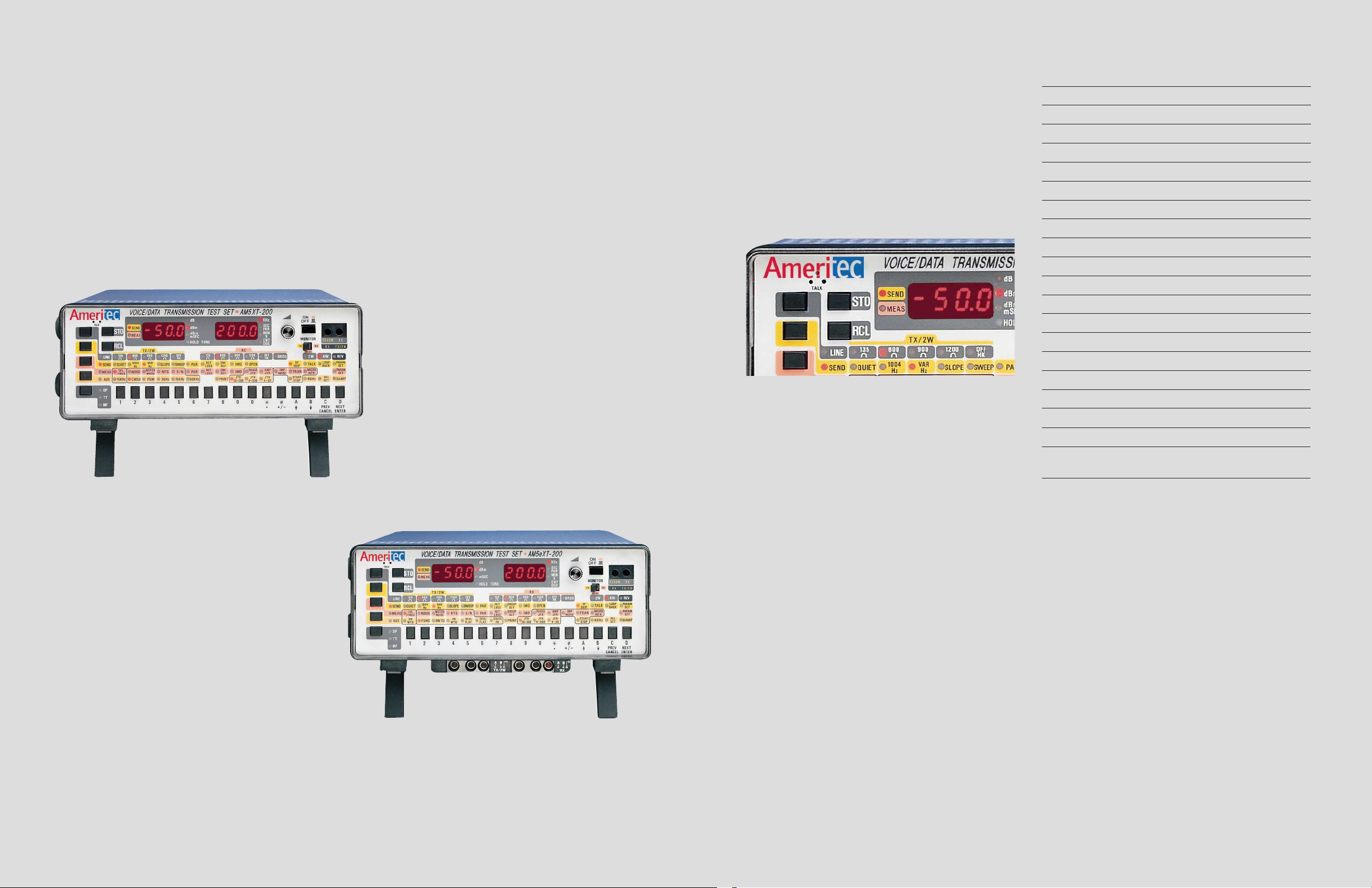
Model AM5XT-200 / IEEE 743-1984 Standard /200kHz Bandwidth
Introduction
Ameritec’s AM5 series of Wideband
Transmission Test Sets are engineered for
peak performance in the field and the lab.
They offer a full range of transmission impairment measurements, a highly versatile signal
generator and basic telephone signaling in a
single compact, portable unit.
The AM5’s perform most standard tests,
worldwide. The AM5XT-200 meets all North
American IEEE 743-1984 standards.
The AM5eXT-200 meets international ITU
standards and is CE approved for use in the
European Community.
The AM5XT-200 and AM5eXT-200 operate
with a bandwidth of 20Hz to 200kHz. The
units can perform qualification tests on
circuits carrying voice band telephone, high
quality audio, DDS to 64KBPS, Basic Rate
ISDN, HDSL, or other services using up to
200kHz bandwidth.
Model AM5eXT-200/International ITU Standard /200kHz
Bandwidth
(shown with optional Siemens connectors)
1
AM5XT store and recall buttons
AM5XT AM5eXT
IEEE 743-1984 Standard X
ITU Standard X
dBm Level (15kHz or 200kHz Filter)* X X
dBm Loss (15kHz or 200kHz Filter)* X X
Frequency X X
Frequency Response (Attenuation Distortion) X X
Noise (Wideband or with Filters) X X
Noise with Tone (Wideband or with Filters) X X
S/N Ratio (Wideband or with Filters) X X
Noise to Ground (Wideband or with Filters) X X
Impulse Noise (Wideband or with Filters) X X
Phase Jitter X X
Amplitude Jitter X X
Micro Interruptions X X
Group Delay X
Envelope Delay X
P/AR X X
Inter-Modulation Distortion (4 Tone/2 Tone) X X
2 & 4 Wire Return Loss X X
Transients (Including Phase & Gain Hits X X
Impulse Noise with Tone & Interruptions)
Ease of Operation/Store and
Recall
The front panel is arranged as a 5 x 16 push button
matrix which allows simple control of all line, send,
measure, auxiliary and signaling functions and still
allows the operator to view the unit’s configuration at a
glance. No need to scroll or hunt through confusing
menus.
For simplicity of operation, up to 40 test set-ups can be
stored in non-volatile memory for instant recall. The
complete test set-up is always displayed, but operation is
simplified to a few keystrokes.
When using a pair of AM5 series units, the local unit
can exercise remote control over the distant unit through
test set-up recall commands issued over the line under
test.
An extensive “Help Directory” in memory can be
viewed or printed via the optional RS232 port.
Audio Monitor and Speaker
Phone
The built-in speaker allows the operator to audibly
monitor either the send or receive line under test. A
built-in microphone provides “Speaker Phone” or “Push
to Talk” operation over the line under test.
Field, Lab or System Use
The units fit anywhere. Use the basic unit as a bench
top laboratory instrument, or, with the addition of
internal sealed lead acid battery pack and soft case, as a
highly compact field instrument. Battery capacity
provides for up to eight hours of uninterrupted use
between charges.
If your application dictates, add the optional rack
mounting kit and RS232 remote control port and
integrate it into a system for network testing.
A Wide Variety of Measurements
The AM5 series performs all common voice/data
analog transmission tests. All measurements are fully
auto-ranging and may either be viewed on the bright
LED display or output to a printer.
Fully Programmable Signal
Generator
Any frequency in the 20Hz to 200kHz band can easily
be selected at any level from -50dB to +10dB.
The following pre-set modes are available to facilitate
measurement.
• 1004Hz
• Loop Back Tone (Operator Pre-Settable)
• Slope Tones
• Frequency Sweep (With or Without SF Skip)
• P/AR Test tone
• ERL, SRL-LO, SRL-HI Tones for Return Loss
Measurements
• Envelope Delay or Group Delay Tones
• 4 Tone or 2 Tone for IMD Measurements
All test tones meet industry standards for purity and
accuracy.
The following measurements are provided:
*AM5XT-200 and AM5eXT-200 provide 200kHz Bandwidth
2
Page 3
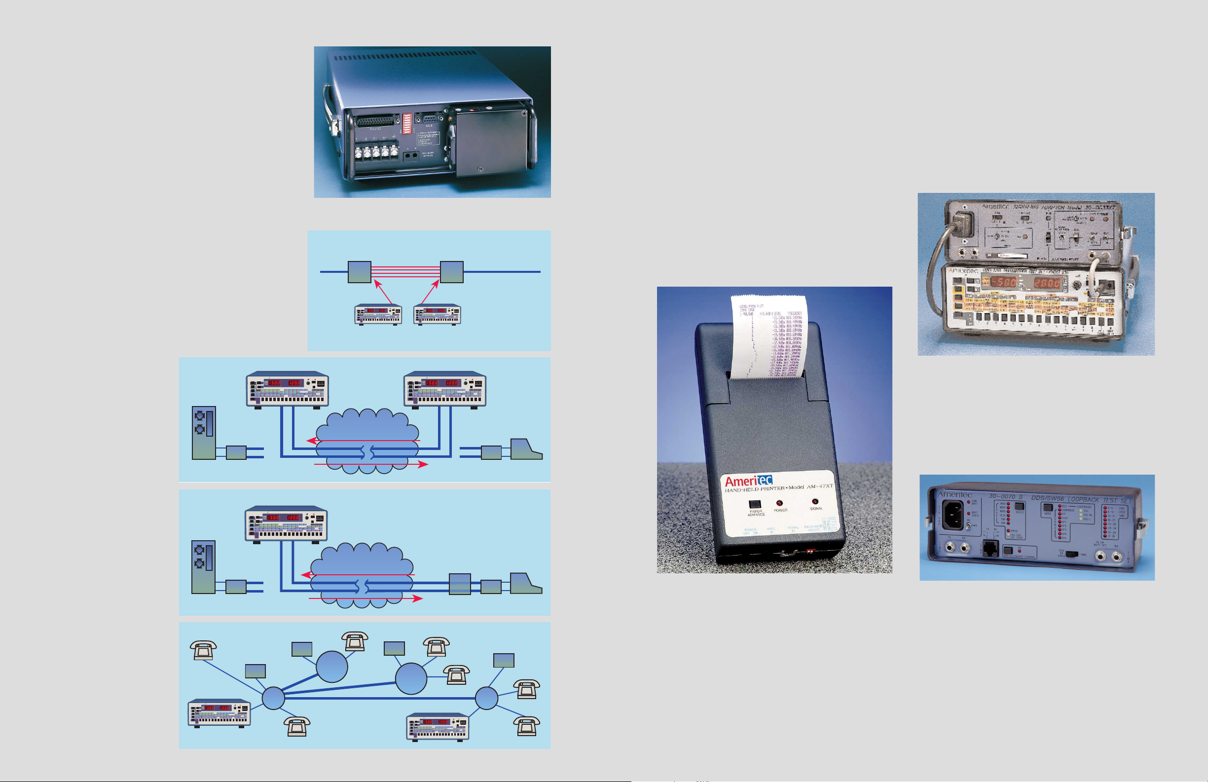
Use two sets for a complete
end-to-end test of 4 wire data
lines.
Use a single unit with an
Ameritec AM3 Series 4
Wire Responder for centralized loopback testing.
Use the AM5XT/eXT built-in
dial capability on dial-up
networks to access a distant
Ameritec AM3 Series 2 Wire
Responder or a second
AM5XT/eXT for centralized
2 wire testing.
AM-47XT accessory printer.
AM5XT-200 instrument with 30-0033XT Signaling Adaptor
Model 30-0070 S DDS/SW56 Loopback Test Set.
AM5eXT rear panel
Built-In Signaling
The AM5 series units are unique among most transmission test sets in that they provide basic loop start line
signaling. They include separate On Hook/Off Hook DC
Hold Circuits for Send and Receive Line and the ability to
signal using Dial Pulse, DTMF or MF(R1).
This feature is useful in testing dial-up circuits or in
commanding responder devices (such as the Ameritec
AM3 Series) on 4 wire dedicated circuits.
Remote Control
All front panel functions may be remote controlled by
simple ASCII character strings to the optional RS232 port.
There is even an “Auxiliary” port which can be used to
chain the AM5XT to a second device (for example, a
co-located test access switch such as the Ameritec AM6),
achieving dual control from a single terminal or computer.
When AM5XT units are used at each end of a line under
test, the distant AM5XT signal generator can be
commanded to recall test set-ups by sending DTMF
commands from the local unit.
XY Plotter Output
(option 25-0045)
Optional rear panel analog outputs are provided for
driving an XY plotter or strip chart recorder. This is
useful in graphing frequency response, plus group or
envelope delay results. This option is standard on the
AM5eXT-200 (CE).
Print or Plot Your Results
An accessory printer (Model AM-47XT) is available
for use with the unit. When connected to the optional
RS232 port, the printer can run a hard copy of any test
set-up and/or measurement result. When making
envelope delay, group delay or frequency response tests,
the “Print Lock” feature may be engaged for an
automatic printed record of the test results in both
graphic and numeric form.
Model 30-0033XT Signaling
Adaptor
The Model 30-0033XT is a Signaling Adaptor
packaged within the cover (lid) of an AM5 Series
Transmission Test Set or can be used as a stand alone
unit. It provides for Loop Start, Ground Start, DID and
Types 1, 2 and 3 E&M signaling. It also incorporates a
ring generator with manual cadence selection and
automatic ring trip. The unit supplies switch selectable -24
and -48 VDC line supply voltages and a switch to allow
for simulation of 1240 Ω loop resistance.
DDS/SW56 Loopback Test Set
30-0070 S:
The DDS Loopback Test Set provides CSU Loopback,
DSU Non-Latching Loopback, DSU Latching Loopback
and a Manual (or Forced) Loopback. DSU Latching is
accomplished with or without secondary channel.
The unit will transmit straightaway test patterns to the
distantend withmanual selectionof test patterns511,2047,
SP1, SP2, SP3, SP4 and SP5. Once again, Secondary
Channel is supported during all straightaway tests.
Supported data rates are 2400, 4800, 9600, 19.2K, 56K,
64K and Switched 56K bits per second.
Switched 56K testing is performed by connecting a
telephone butt set or AM5XT to the TIMS TX port to
provide ON/OFF Hook and pulse dial functions. Far end
signaling (wink, delay, answer) is indicated via front
panel LED.
HDSL Testing
With 200kHz bandwidth, the AM5XT-200 performs
full HDSL (High-bit-rate Digital Subscribers Line)
testing. HDSL provides DS1 (1.544Mbps) compatibility over two copper twisted pairs with each pair
carrying a 2B1Q full duplex data stream. These pairs
are tested configuring an AM5XT-200 to generate a sine
wave of 196kHz and then making the appropriate level,
noise and frequency measurements.
3 4
Application: HDSL Circuit Testing
HDSL Modem HDSL Modem
VOICE DATA TRANSMISSION TEST SET Model
Ameritec
d
d
ST
d Bm
mSE
HOLD
RC
AM5-200
2 Wire or 4 Wire Mode
ON
KH
OF
SE
C
MI
N
MONITOR
CN
T
MEAS
VOICE DATA TRANSMISSION TEST SET Model
Ameritec
ST
TX/2W
TX/2WRR
RC
AM5-200
Prequalify the HDSL
• Load Coil Test
• Level/Freq. Test
• Background Noise
w/Wideband Filter
ON
KH
d
OF
SE
d
C
MI
d Bm
N
mSE
MONITOR
TX/2W
CN
HOLD
T
TX/2WRR
MEAS
• Longitudinal
Balance
(Noise/Grd (-)
CMSG)
• Impulse Noise
CPU
CPU
AM5XT/eXT
VOICE DATA TRANSMISSION TEST SET Model
Ameritec
d
d
ST
d Bm
mSE
HOLD
RC
AM5XT/eXT
VOICE DATA TRANSMISSION TEST SET Model
Ameritec
MODEM MODEM
ST
RC
RCV
d
d
d Bm
mSE
HOLD
ON
KH
OF
SE
C
MI
N
MONITOR
TX/2W
CN
T
TX/2WRR
MEAS
TELEPHONE NETWORK
XMIT
Ameritec
ST
RC
VOICE DATA TRANSMISSION TEST SET Model
AM5XT/eXT
d
d
d Bm
mSE
HOLD
XMIT
RCV
ON
KH
OF
SE
C
MI
N
MONITOR
TX/2W
CN
T
TX/2WRR
MEAS
AM5XT/eXT
VOICE DATA TRANSMISSION TEST SET Model
Ameritec
d
d
ST
d Bm
mSE
HOLD
RC
ON
KH
OF
SE
C
MI
N
MONITOR
TX/2W
CN
T
TX/2WRR
MEAS
RESPONDER (AM3-4)
LOOPBACK QUIET
SEND TONES
MODEM MODEM
RCV
TELEPHONE NETWORK
XMIT
2W RESPONDER
KH
SE
C
MI
N
CN
T
(AM3-2)
ON
OF
MONITOR
TX/2W
TX/2WRR
MEAS
CO
PBX
LOCAL
C.O.
FX
TIE
TELEPHONE NETWORK
DISTANT
C.O.
Ameritec
AMPUTATE
XMIT
RCV
AM5XT/eXT
VOICE DATA TRANSMISSION TEST SET Model
KH
d
SE
d
ST
RC
C
MI
d Bm
N
mSE
CN
HOLD
T
2W RESPONDER
(AM3-2)
PBX
ON
OF
MONITOR
TX/2W
TX/2WRR
MEAS
DTE
DTE
Page 4
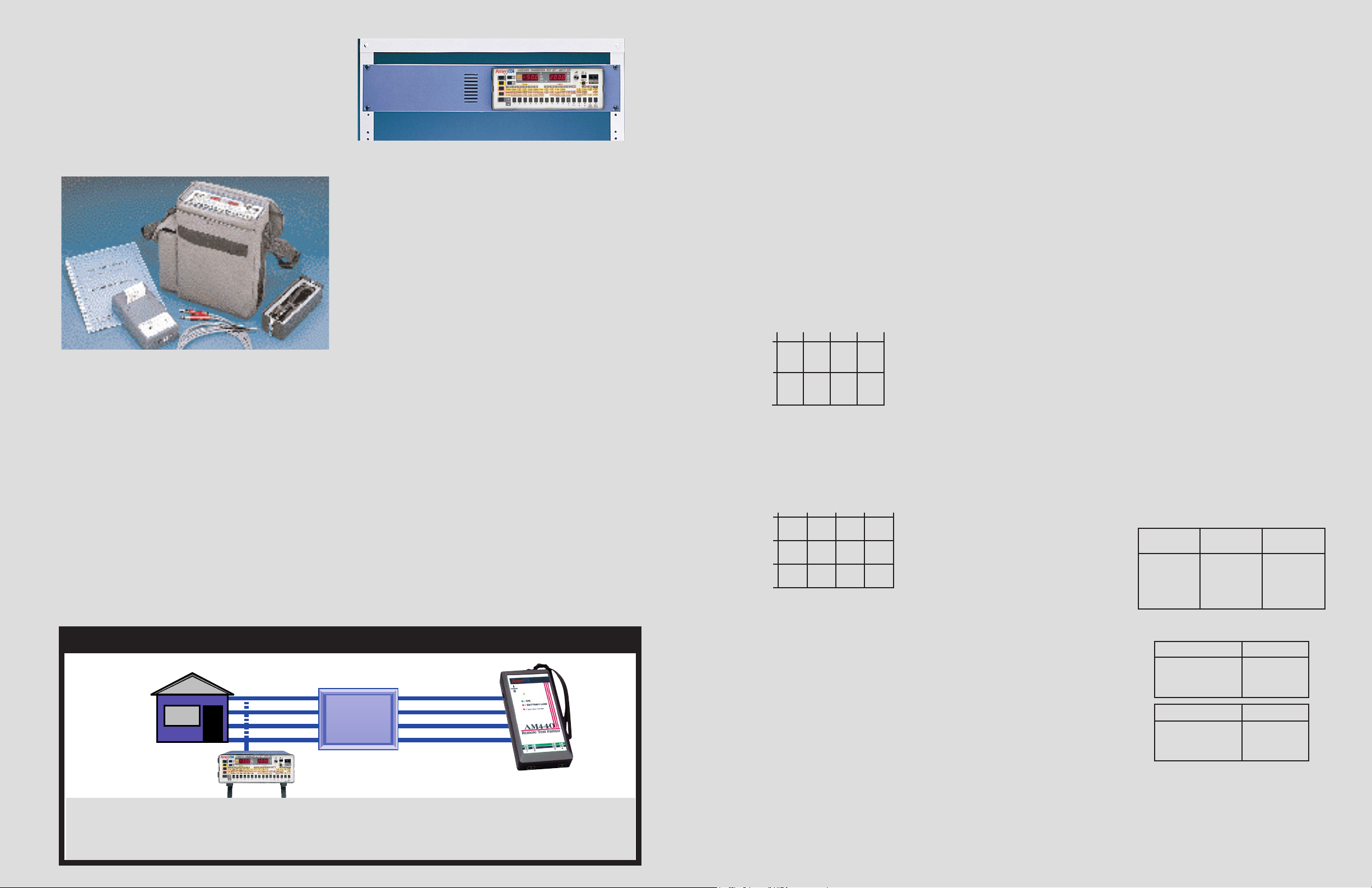
Unit with cover, manual, power cord, optional soft case, printer and cables.
Unit shown in rack mount configuration.
The DDS Loopback Test Set is packaged into a front
panel cover lid for an Ameritec AM5XTseries
Transmission Test Set. It can also be used as a stand
alone unit.
DDS Loopback Test Set 30-0070
Similar to the 30-0070 S Test Set except without
SW56 capability.
Accessories and Options
Provided: Model AM5XT-200 or AM5eXT-200,
or AM5eXT (CE) removable front cover with cord
storage, power cord and instruction manual.
Portable or Rack Mount: No other analog
transmission test set this full-featured is so convenient.
About the size and weight of a telephone directory, it is
easily transported from lab to field. For permanent
installations, a rack mounting kit is available for the
AM5XT and AM5eXT models which will allow 19”
relay rack mounting in only two rack increments of
space.
Optional Battery: An optional internal, recharge-
able battery pack is available for full portable “cordless”
operation. The batteries are of the sealed lead acid type
and require no maintenance. A front panel low battery
indicator indicates when recharging is needed.
The built-in chargerallowsthebatteriestobecharged
even while the unit is in operation.
Options:
25-0019 RS232Remote Control Port with Auxiliary
RS232 Output Port. This option required
for printer plotting or printer output.
Included with AM5eXT-200(CE).
24-0017 Internal Power Pack (Sealed Rechargeable
Lead Acid Batteries) and Internal Charger.
Included with AM5eXT-200(CE).
25-0041 “Siemens” Type Line Test Set Connections.
25-0045 Analog XY Plotter Output(Prerequisite
25-0019) Included with AM5eXT-200(CE).
25-0145 Adds 310 type input jacks.
25-0240 Complex Impedance (AM5eXT-200).
Contact factory for details.
Accessories:
30-0025 -48 VDC Source Battery Cover
30-0033XT Signaling Adaptor Cover
30-0070 DDS Loopback Test Set Cover
30-0070 S DDS/SW56 Loopback Test Set Cover
87-0070B Padded Soft Carrying Case with Pouch for
AM-47XT Printer.
AM-47XT Hand-Held Printer Plotter with Integral
Rechargeable Batteries. Includes a Roll of
Paper, AC Adaptor, Connecting Cable.
Prerequisite: Option 25-0019
26-0014 Replacement Paper for AM-47XT.
26-0015 Replacement Ink Cartridge for AM-47XT.
85-0076 19” Rack Mount Kit.
48-0062 6 Ft. Bantam to Clip Input Cable, two Req.
48-0047 6 Ft. Bantam to Bantam Input Cable, twoReq.
48-0048 6 Ft. Bantam to 310 Input Cable, two Req.
Single Technician End-to-End Testing
Up to 4 pairs Tested • Voice Response to Commands
Through its DTMF dialing capability the AM5 commands the AM440 to:
• Open Tip and Ring for foreign voltage tests • Short Tip to Ring to measure loop resistance
• Ground Tip and Ring for resistance to ground measurements • Quiet Termination for Noise or Impulse Noise testing
• Transmit preset tones from 304Hz to 384kHz, slopes, sweeps• Test for Load Coils
APPLICATION: AM5 and the AM440 Remote Testing Partner
5
Relative Level
Reading
Relative Level
Accuracy
Absolute Level
Accuracy
0 to 10dB
10 to 30dB
30 to 40dB
40 to 50dB
± .15dB
± .3dB
± .5dB
± 1dB
± .25dB
± .3dB
± .5dB
± 1dB
Measuring Frequency Additional Error
200 to 400Hz
400 to 600Hz
600 to 20kHz
± 50 µs
± 15 µs
± 5 µs
Amplitude Variation Additional Error
0 to 10dB
10 to 30dB
30 to 50dB
± 5 µs
± 10 µs
± 20 µs
Technical
Specifications
LEVEL FREQUENCY
Transmitter
Var Mode: 20Hz to 200kHz in 10 or 100Hz steps or
Direct Numeric Entry
1004Hz Mode: 1004Hz Fixed
Slope Mode: (AM5XT) 404, 1004, 3004Hz @ 5 sec.
each.
(AM5eXT) 304, 1004, 2004, 3004Hz @
5 sec. each.
Sweep Mode: Start Freq: 20Hz - 200kHz
Stop Freq: 20Hz - 200kHz
Stop Size: 1Hz - 119.9kHz
Step Dwell: 1/4 sec. - 999.9 sec.
Inter Sweep Delay:1/4 sec.- 999.9sec.
SF Skip: (AM5XT) 2450 - 2750Hz
(AM5eXT) 2130 - 2430Hz
Frequency Accuracy: ± .01%
Level Range: -50dBm to +10dBm
Resolution: .1dB
Accuracy: 20 200 20K 150K 200kHz
+10
±.25 ±.1 ±.25 ±.5
-40
±.5 ±.5 ±.5 ±.10
-50
Accuracy: 20 200 20K 150K 200kHz
+10
±.5 ±.2 ±.5 ±1.0
-40
±.5 ±.2 ±.5 ±2.0
-50
±1.0 ±1.0 ±1.0 ±3.0
NOISE (CONTINUED)
Resolution: 1dB
Accuracy: (AM5XT) ±1dB @ 20 to +99dBrn ±2dB
@ 10 to 20dBrn (±1dB CMSG.)
(AM5eXT) ±1dB @ -70 to +10dBm ±2dB
@ -80 to -70dBm (±1dB PSHO).
Filters: (AM5XT)160kHz Lo Pass C Message,
Program, 3kHz Flat, 15kHz Flat, 50KBit,
60Hz
(AM5eXT) 160kHz Lo Pass Psophometric
[P.53], Sound WTD [J.16], 3kHz Flat (2753250Hz 0.71), 2kHz Flat (750 - 2300Hz
0.71), 60Hz
Detector: (AM5XT) RMS
(AM85e) RMS or Quasi Peak [J.16]
NOTCH NOISE (NOISE WITH TONE)
Transmitter:
1004Hz (Holding Tone)
Receiver:
Notch: 995 - 1025Hz >50dB - (0.132)
Other Specifications Same as ÒNoiseÓ Above.
NOISE TO GROUND
Transmitter:
Quiet Termination
Receiver:
Range: (AM5XT) 40 to 129dBrn
(AM5eXT) -50 to +39dBm
Resolution: 1dB
Accuracy: ±1.5dB
Filters/Detector:- Same as ÒNoiseÓ Above -
SIGNAL TO NOISE RATIO (0.132)
Transmitter:
1004Hz (Holding Tone)
Receiver:
Signal Range: -40 to +10dBm
Noise Range: (AM5XT) 10 to 70dBrn
(AM5eXT) -80 to -20dBm
Ratio Range: 10 to 50dB
Accuracy: ±1dB @ 10 to 40dB
±2dB @ 40 to 45dB
±3dB @ 45 to 50dB
Noise below 20dBrn (-70 dBm) reduces accuracy
to ±2dB except when using ÒCMSGÓ filter (AM5XT)
or ÒPSHOÓ filter (AM5eXT)
P/AR
Transmitter:
P/AR Waveform per IEEE 743
Receiver:
Range: 0 to 120 P/AR Units
Resolution: 1 P/AR
Accuracy: ±2 P/AR @ 30 to 110 P/AR
±4 P/AR @ 0 to 30 and 110 to 120 P/AR
Signal Level: -40 to 0dBm (Measured with RMS
Detector)
RETURN LOSS 2W OR 4W
Transmitter:
Band Limited White Noise (ERL,
SRL LO, SRL HI) or Sine Wave @ -10 to -2dBm
Receiver
Range: 0 to 40dB (2 Wire), 0 to 50dB (4 Wire)
Resolution: .1dB
Accuracy: ± .5dB
Transhybrid Loss Compensation
(TLP): -99.9 to +99.9dB
Detector: True RMS
ENVELOPE DELAY (AM5XT ONLY) PER
IEEE 743
Transmitter:
Level Range: -40 to 0dBm
Accuracy: ± .2dBm
Carrier Freq.: 200Hz to 4kHz
Carrier Step Size: 1Hz to 3800Hz
Carrier Step Rate: 1/4 sec. to 999.9 sec.
Accuracy: ± 5 µs @ 600 to 4000Hz
± 15 µs @ 200 to 599Hz
Receiver:
Level Range: -40 to +10 dBm
Accuracy: ± .2dBm
Delay Range: -3000 to +9000 us
Resolution: 1 µs
Accuracy: ± 5 µs @ 600 to 4000Hz
± 15 µs @ 200 to 599Hz
(Accuracy Valid for S/N Ratios >24dB)
Display Averaging: 1/4 sec. to 4 sec.
General:
Mode: Normal, Repeat or Hold
Modulation Frequency: 83-1/3Hz
GROUP DELAY (AM5eXT ONLY) PER
ITU 0.81
Transmitter:
Reference Carrier: 200Hz to 20kHz (1.8kHz Default)
Measuring Carrier: 200Hz to 20kHz
Delay Error: ±5 µs @ 200 - 400Hz
±3 µs @ 400 - 600Hz
±1 µs @ 600 - 20kHz
Measuring Sweep: Step Size: 1 - 9999Hz
Step Rate: 1/4 sec. to 999.9 sec.
Level Range: -40 to 10dBm
Level Accuracy: ± .2dB
Receiver:
Input Level Range:-50 to +10dBm (-40 to
+10dBm for 135 ½ to 150 ½)
Level Measurement Accuracy:
(Accuracy not specified below 400Hz when using
135 ½ (AM5XT) or 150 ½ (AM5eXT) TX termination).
Maximum output is +6dBmwhen using 135½ or 150 ½.
Receiver:
Level Range: -64.9dBm to +10dBm
Resolution: .1dB
Display Averaging: 1/4 sec. to 4 sec.
Filter: Switchable 4kHz Low Pass
General:
Modulation Signal: 41.66Hz (40% AM)
Identifying Signal: 166.6Hz (20% AM)
Changeover Period: 240ms
Delay Range: -12,000 to +12,000
Delay Accuracy: 1% of Reading + Errors Below
Accuracy is ± .1dB @ 1004 - 1020Hz @ 0 to 20dBm (Accuracy not specified below 400Hz when
using 135 ½ (AM85) or 150 ½ (AM85e) TX termination)
Detector: Average
Filters: (AM85)120kHz Lo Pass, 15kHz Lo Pass,
60Hz Hi Pass
(AM85e) 120kHz Lo Pass, Sound UN WTD
(J.16), 60Hz Hi Pass
Frequency Range: 20Hz to 200kHz*
Resolution/Accuracy: ± 0.01% of reading ± 1 count
Sensitivity: -55dBm to + 10dBm with S/N Ratio
>20dB
NOISE
Transmitter:
Quiet Termination
Receiver:
Range: (AM85) 10 to 99dBrn (20 to 99dBrn @
135 ½)
(AM85e) -80 to +9dBm (-70 to +9 dBm @
150 ½)
6
T/R 1
CUSTOMER
PREMISES
T/R 2
T/R 3
T/R 4
T/R 1
Distribution
Panel
or
MDF
T/R 2
T/R 3
T/R 4
AM440
 Loading...