


MODEL AM5/AM5e
Classic
WIDEBAND
TRANSMISSION TEST SET
INSTRUCTION MANUAL

MODEL AM5/AM5e
Classic
WIDEBAND
TRANSMISSION TEST SET
INSTRUCTION MANUAL
May 1997
Technical Data Subject to
Change without Notice
760 Arrow Grand Circle Covina, CA 91722 USA TEL 626.915.5441 FAX 626.915.7181 www.ameritec.com
Test Complete
ISO 9001 Certified Company
For extra copies of
this manual, order
Part No. 18-0047G
AM5(e) Classic Instruction Manual |
(18-0047) |
Record of Revisions |
RECORD OF REVISIONS
00 |
March, 1993 |
Original Issue |
|
|
|
A |
August, 1993 |
Corrections on page 3-5. |
|
|
|
B |
December, 1993 |
Corrections on page 4-7, 10-3. |
C |
April, 1994 |
Major update |
|
|
|
D |
June, 1994 |
Added INDEX |
|
|
|
E |
October, 1994 |
Major update |
|
|
|
F |
August, 1996 |
Added E-mail address |
|
|
|
G |
April, 1997 |
Calibrate Procedure Addendum |
|
|
for new software version. |
|
|
|
November 19, 1997 |
iv |

AM5(e) Classic Instruction Manual |
(18-0047) |
DESCRIPTION |
CAUTION
When using the padded carrying case for the AM5 or AM5e Classic (P/N 87-0070C), DO NOT PLACE the power cord around the side of the case in the manner demonstrated in Figure 1.
Instead, be certain to WIND THE CORD UNDER THE CASING in the Area between the feet, as shown in Figure 2.
Failure to follow this procedure could cause deterioration of the cord and Increase the possibility of electric shock.
November 19, 1997
AM5(e) Classic Instruction Manual |
(18-0047) |
INTRODUCTION |
ORGANIZATION OF MANUAL
SECTION 1 — OVERVIEW/UNPACKING describes the models of the AM5 and AM5e Classic that are available and provides guidance for proper unpacking and inspection of the unit.
SECTION 2 — POWER CONSIDERATIONS describes the commercial power requirements, precautions, battery options, and power ON and OFF.
SECTION 3 — PHYSICAL AND FUNCTIONAL DESCRIPTION describes the physical characteristics; front-panel switches, indicators, displays, and connectors; rear-panel power connector, voltage-select switch, fuse location, method of identifying units, and permanent connections. Also described in this section are the Factoryinstalled options and accessories.
SECTION 4 — SELF TEST OPERATIONS describes the operations which should be performed after the unit is turned on for the first time. Default settings are described and SEND and MEASURE tests that can be performed by connecting the TX/2W to the RX jacks are described. This section also describes restoration of settings before shut down and a full-calibration procedure.
SECTION 5 — LINE TEST CONNECTIONS AND CONFIGURATIONS describes the cables that may be used to connect the unit to the equipment under test. Also covered are schematic diagrams of the line interfaces for the various configurations that can be selected by an operator through the use of the TX/2W. RX, LINE, and DIAL sections of the front panel.
SECTION 6 — MEASURE FUNCTIONS AND PARAMETERS describes each measurement that may be selected by the MEASURE key on the front panel. Included in the description are all parameters that may be changed for each type of measurement. Some typical test configurations are covered.
November 19, 1997 |
ii |
AM5(e) Classic Instruction Manual |
(18-0047) |
INTRODUCTION |
SECTION 7 — FILTERS FOR AM5 Classic describes the Noise-Weighting filters that are provided to IEEE standards.The Filters are switched by the FILTER key into the measurement circuitry for noise tests. Included in these sections are frequency response graphs for each filter type.
SECTION 8 — FILTERS FOR AM5e Classic describes the Noise-Weighting filters that are provided to CCITT standards.The Filters are switched by the FILTER key into the measurement circuitry for noise tests. Included in these sections are frequency response graphs for each filter type.
SECTION 9 — SEND FUNCTIONS AND PARAMETERS describes each signal generation function that may be selected by the SEND key on the front panel. Included in the description are all parameters that may be changed for each signaling requirement.
SECTION 10 — AM5/AM5e CLASSIC TECHNICAL SPECIFICATIONS provides a tabular listing of the specifications for the AM5 Classic and the AM5e Classic.
SECTION 11 — WARRANTY AND SERVICE POLICY provides information on warranty and on returning unit to Ameritec for service.
November 19, 1997 |
iii |
AM5(e) Classic Instruction Manual |
(18-0047) |
TABLE OF CONTENTS |
|||
|
|
TABLE OF CONTENTS |
|
|
|
CAUTION |
. . . . . . |
. . . . . . . . . . . . . . . . . . |
. . . . . . . . . . . . . . |
INSIDE OF FRONT COVER |
|
SECTION 1 ó OVERVIEW AND UNPACKING . . . . . |
. . . . . . . . . . . . . . . . . . . . . |
1 ñ 1 |
|||
1.1 |
OVERVIEW . . . . . . . . . . . . |
. . . . . . . . . . . . . . . |
. . . . . . . . . . . . . . . . . . . . |
1 ñ 1 |
|
1.2 |
UNPACKING . . . . . . . . . . |
. . . . . . . . . . . . . . . |
. . . . . . . . . . . . . . . . . . . . |
1 ñ 1 |
|
SECTION 2 ó POWER CONSIDERATIONS . . . . . . . . . |
. . . . . . . . . . . . . . . . . . . . |
2 ñ 1 |
|||
2.1 |
COMMERCIAL POWER . |
. . . . . . . . . . . . . . . |
. . . . . . . . . . . . . . . . . . . . |
2 ñ 1 |
|
|
|
CAUTION: . . . . . . . |
. . . . . . . . . . . . . . . |
. . . . . . . . . . . . . . . . . . . . |
2 ñ 1 |
2.2 |
OPTIONAL BATTERY PACK . . . . . . . . . . . . |
. . . . . . . . . . . . . . . . . . . . |
2 ñ 1 |
||
2.3 POWER ON AND OFF . . . |
. . . . . . . . . . . . . . . |
. . . . . . . . . . . . . . . . . . . . |
2 ñ 1 |
||
SECTION 3 ó PHYSICAL AND FUNCTIONAL DESCRIPTION . . . . . . . . . . . |
3 ñ 1 |
||||
3.1 |
PHYSICAL CHARACTERISTICS . . . . . . . . . |
. . . . . . . . . . . . . . . . . . . . |
3 ñ 1 |
||
|
3.1.1 |
Weight . . . . . . . . . . . |
. . . . . . . . . . . . . . . |
. . . . . . . . . . . . . . . . . . . . |
3 ñ 1 |
|
3.1.2 |
Portable Dimensions . . . . . . . . . . . . . . |
. . . . . . . . . . . . . . . . . . . . |
3 ñ 1 |
|
|
3.1.3 |
Rack Mounted Dimensions . . . . . . . . |
. . . . . . . . . . . . . . . . . . . . |
3 ñ 1 |
|
|
3.1.4 |
Construction . . . . . . |
. . . . . . . . . . . . . . . |
. . . . . . . . . . . . . . . . . . . . |
3 ñ 1 |
|
|
CAUTION: . . . . . . . |
. . . . . . . . . . . . . . . |
. . . . . . . . . . . . . . . . . . . . |
3 ñ 1 |
|
3.1.5 |
Rubber Feet . . . . . . . |
. . . . . . . . . . . . . . . |
. . . . . . . . . . . . . . . . . . . . |
3 ñ 1 |
|
3.1.6 |
Carrying Handle . . |
. . . . . . . . . . . . . . . |
. . . . . . . . . . . . . . . . . . . . |
3 ñ 1 |
|
|
NOTE . . . . . . |
. . . . . . . . . . . . . . . |
. . . . . . . . . . . . . . . . . . . . |
3 ñ 1 |
3.2 |
FRONT PANEL DESCRIPTION . . . . . . . . . . |
. . . . . . . . . . . . . . . . . . . . |
3 ñ 1 |
||
|
|
CAUTION . . . . . . . |
. . . . . . . . . . . . . . . |
. . . . . . . . . . . . . . . . . . . . |
3 ñ 1 |
|
|
NOTE . . . . . . |
. . . . . . . . . . . . . . . |
. . . . . . . . . . . . . . . . . . . . |
3 ñ 1 |
|
3.3.1 |
ON OFF Button (power switch) . . . . |
. . . . . . . . . . . . . . . . . . . . |
3 ñ 5 |
|
|
|
CAUTION . . . . . . . |
. . . . . . . . . . . . . . . |
. . . . . . . . . . . . . . . . . . . . |
3 ñ 5 |
|
|
NOTE . . . . . . |
. . . . . . . . . . . . . . . |
. . . . . . . . . . . . . . . . . . . . |
3 ñ 5 |
|
3.3.2 |
TX/2W bantam jack for 2-wire circuits (2W LED on) . . . . . . |
3 ñ 5 |
||
|
3.3.3 |
TX/2W bantam jack for 4-wire circuits (4W LED on) . . . . . . |
3 ñ 5 |
||
|
3.3.4 |
TX/2W bantam jack for REVERSE selection |
|
||
|
|
(4W REV LED on) . |
. . . . . . . . . . . . . . . |
. . . . . . . . . . . . . . . . . . . . |
3 ñ 5 |
|
3.3.5 |
RX bantam jack for 4-wire circuits (4W LED on) . . . . . . . . . . |
3 ñ 5 |
||
|
3.3.6 |
RX bantam jack for 4-wire circuits for REVERSE selection |
|
||
|
|
(4W REV LED on) . |
. . . . . . . . . . . . . . . |
. . . . . . . . . . . . . . . . . . . . |
3 ñ 5 |
|
3.3.7 |
MONITOR (TX, MEAS, RX) switch . |
. . . . . . . . . . . . . . . . . . . . |
3 ñ 6 |
|
|
3.3.8 |
Speaker Volume Control . . . . . . . . . . |
. . . . . . . . . . . . . . . . . . . . |
3 ñ 6 |
|
|
|
NOTE . . . . . . |
. . . . . . . . . . . . . . . |
. . . . . . . . . . . . . . . . . . . . |
3 ñ 6 |
|
3.3.9 |
DISPLAY key . . . . . |
. . . . . . . . . . . . . . . |
. . . . . . . . . . . . . . . . . . . . |
3 ñ 6 |
|
3.3.10 |
Left-Hand 7-Segment Display . . . . . . |
. . . . . . . . . . . . . . . . . . . . |
3 ñ 6 |
|
|
3.3.11 |
Left-Hand LEDís (dB, dBm, dBrn, mSEC, HOLD TONE) . . . |
3 ñ 6 |
||
|
3.3.12 |
Right-Hand 7-Segment Display . . . . |
. . . . . . . . . . . . . . . . . . . . |
3 ñ 8 |
|
|
3.3.13 |
Units of Measurement LEDís (kHz, SEC, MIN, CNT) . . . . . . |
3 ñ 8 |
||
|
3.3.14 |
PARAM SEL keys (Parameter Select and arrow keys) . . . . . |
3 ñ 8 |
||
|
|
NOTE . . . . . . |
. . . . . . . . . . . . . . . |
. . . . . . . . . . . . . . . . . . . . |
3 ñ 8 |
|
3.3.15 START/STOP Key (Impulse Noise Measurement) . . . . . . . . |
3ñ10 |
|||
|
3.3.16 MEASURE Key . . . |
. . . . . . . . . . . . . . . |
. . . . . . . . . . . . . . . . . . . . |
3ñ10 |
|
November 19, 1997 |
v |
AM5(e) Classic Instruction Manual |
(18-0047) |
TABLE OF CONTENTS |
|||
|
3.3.17 FILTER (left key) . . |
. . . . . . . . . . . . . . . . . . . . |
. . . . . . . . . . . . . . . . |
3ñ11 |
|
|
|
NOTE . . . . . |
. . . . . . . . . . . . . . . . . . . . |
. . . . . . . . . . . . . . . . |
3ñ11 |
|
3.3.18 |
FILTER (right key) . |
. . . . . . . . . . . . . . . . . . . |
. . . . . . . . . . . . . . . . |
3ñ11 |
|
3.3.19 |
SEND (left key) . . . |
. . . . . . . . . . . . . . . . . . . |
. . . . . . . . . . . . . . . . |
3ñ12 |
|
3.3.20 |
SEND (middle key) |
. . . . . . . . . . . . . . . . . . . |
. . . . . . . . . . . . . . . . |
3ñ12 |
|
3.3.21 |
SEND (right key) . . |
. . . . . . . . . . . . . . . . . . . |
. . . . . . . . . . . . . . . . |
3ñ12 |
|
|
NOTE: . . . . . |
. . . . . . . . . . . . . . . . . . . |
. . . . . . . . . . . . . . . . |
3ñ12 |
|
3.3.22 |
TX/2W (left key) . . |
. . . . . . . . . . . . . . . . . . . |
. . . . . . . . . . . . . . . . |
3ñ13 |
|
3.3.23 |
TX/2W (right key) . |
. . . . . . . . . . . . . . . . . . . |
. . . . . . . . . . . . . . . . |
3ñ13 |
|
3.3.24 |
RX (left key) . . . . . . |
. . . . . . . . . . . . . . . . . . . |
. . . . . . . . . . . . . . . . |
3ñ13 |
|
3.3.25 |
RX (middle key) . . . |
. . . . . . . . . . . . . . . . . . . |
. . . . . . . . . . . . . . . . |
3ñ13 |
|
3.3.26 |
RX right key) . . . . . |
. . . . . . . . . . . . . . . . . . . |
. . . . . . . . . . . . . . . . |
3ñ13 |
|
3.3.27 |
LINE Key . . . . . . . . |
. . . . . . . . . . . . . . . . . . . |
. . . . . . . . . . . . . . . . |
3ñ14 |
|
3.3.28 |
DIAL key . . . . . . . . . |
. . . . . . . . . . . . . . . . . . . |
. . . . . . . . . . . . . . . . |
3ñ14 |
|
3.3.29 |
DIAL Terminals: . . |
. . . . . . . . . . . . . . . . . . . |
. . . . . . . . . . . . . . . . |
3ñ14 |
3.4 |
REAR PANEL . . . . . . . . . . |
. . . . . . . . . . . . . . . . . . . |
. . . . . . . . . . . . . . . . |
3ñ15 |
|
|
|
NOTE . . . . . . |
. . . . . . . . . . . . . . . . . . . |
. . . . . . . . . . . . . . . . |
3ñ15 |
|
3.4.1 |
AC Power Selector Switch . . . . . . . . . . . . . |
. . . . . . . . . . . . . . . . |
3ñ15 |
|
|
|
CAUTION: . . . . . . . |
. . . . . . . . . . . . . . . . . . . |
. . . . . . . . . . . . . . . . |
3ñ15 |
|
3.4.2 |
Fuse Holder . . . . . . |
. . . . . . . . . . . . . . . . . . . |
. . . . . . . . . . . . . . . . |
3ñ15 |
|
3.4.3 |
Power Plug . . . . . . . |
. . . . . . . . . . . . . . . . . . . |
. . . . . . . . . . . . . . . . |
3ñ15 |
|
3.4.4 |
Identification Label |
. . . . . . . . . . . . . . . . . . . |
. . . . . . . . . . . . . . . . |
3ñ15 |
|
3.4.5 |
Screw Terminal, Ground . . . . . . . . . . . . . . |
. . . . . . . . . . . . . . . . |
3ñ16 |
|
|
3.4.6 |
Screw Terminals, T1 and R1 . . . . . . . . . . . |
. . . . . . . . . . . . . . . . |
3ñ16 |
|
|
3.4.7 |
Screw Terminals, T and R . . . . . . . . . . . . . |
. . . . . . . . . . . . . . . . |
3ñ16 |
|
3.5 OPTIONAL FACTORY-INSTALLED EQUIPMENT . . . . . . . . . . . . . |
3ñ17 |
||||
|
3.5.1 |
Sealed Lead-Acid Batteries and Integral Charger |
|
||
|
|
(Option 24-0017) . . |
. . . . . . . . . . . . . . . . . . . |
. . . . . . . . . . . . . . . . |
3ñ17 |
|
3.5.2 |
Siemens type ìbananaî input adapter for AM5e Classic |
|
||
|
|
only (Option 25-0041) . . . . . . . . . . . . . . . . . |
. . . . . . . . . . . . . . . . |
3ñ17 |
|
|
3.5.3 |
Model 30-0033XT Signalling Adapter with Ring Generator . |
3ñ17 |
||
3.6 |
ACCESSORIES . . . . . . . . . . |
. . . . . . . . . . . . . . . . . . . |
. . . . . . . . . . . . . . . . |
3ñ18 |
|
|
3.6.1 |
Line Cables . . . . . . . |
. . . . . . . . . . . . . . . . . . . |
. . . . . . . . . . . . . . . . |
3ñ18 |
|
3.6.2 |
Protective front panel (85-0078) . . . . . . . . . |
. . . . . . . . . . . . . . . . |
3ñ18 |
|
|
|
NOTE . . . . . |
. . . . . . . . . . . . . . . . . . . |
. . . . . . . . . . . . . . . . |
3ñ18 |
|
3.6.3 |
Padded Carrying Case (87-0070) . . . . . . . . |
. . . . . . . . . . . . . . . . |
3ñ18 |
|
|
3.6.4 |
19î Rack Mounting Kits (85-0076) . . . . . . |
. . . . . . . . . . . . . . . . |
3ñ18 |
|
|
3.6.5 |
19î Rack Mounting Shelf (85-0233): . . . . . |
. . . . . . . . . . . . . . . . |
3ñ18 |
|
SECTION 4 ó SELF TEST AND CALIBRATION . . . . . . . . . |
. . . . . . . . . . . . . . . . |
4 ñ 1 |
|||
4.1 |
SELF TEST CONFIGURATION . . . . . . . . . . . . . . |
. . . . . . . . . . . . . . . . |
4 ñ 1 |
||
4.2 POWER ON SELF-TEST . . |
. . . . . . . . . . . . . . . . . . . |
. . . . . . . . . . . . . . . . |
4 ñ 1 |
||
|
|
NOTE . . . . . . |
. . . . . . . . . . . . . . . . . . . |
. . . . . . . . . . . . . . . . |
4 ñ 1 |
November 19, 1997 |
vi |
AM5(e) Classic Instruction Manual |
(18-0047) |
TABLE OF CONTENTS |
|||
4.3 |
DEFAULT SETTINGS . . . |
. . . . . . . . . . . . . . . . . . . |
. . . . . . . . . . . . . . . . . |
4 ñ 1 |
|
|
4.3.1 |
Function LEDs at Power Turn-on . . . . . . . |
. . . . . . . . . . . . . . . . |
4 ñ 1 |
|
|
4.3.2 |
Parameter Settings at Power Turn-on: . . |
. . . . . . . . . . . . . . . . |
4 ñ 2 |
|
|
|
NOTE . . . . . |
. . . . . . . . . . . . . . . . . . . . |
. . . . . . . . . . . . . . . . |
4 ñ 2 |
|
4.3.3 |
Restoring Previous Settings . . . . . . . . . . . . |
. . . . . . . . . . . . . . . . |
4 ñ 3 |
|
|
|
NOTE . . . . . . |
. . . . . . . . . . . . . . . . . . . |
. . . . . . . . . . . . . . . . |
4 ñ 3 |
4.5 |
LOOPBACK TESTS . . . . . . |
. . . . . . . . . . . . . . . . . . . |
. . . . . . . . . . . . . . . . |
4 ñ 4 |
|
|
4.5.1 |
Set up . . . . . . . . . . . . |
. . . . . . . . . . . . . . . . . . . |
. . . . . . . . . . . . . . . . |
4 ñ 4 |
|
4.5.2 |
QUIET Test . . . . . . . |
. . . . . . . . . . . . . . . . . . . |
. . . . . . . . . . . . . . . . |
4 ñ 4 |
|
|
NOTE . . . . . . |
. . . . . . . . . . . . . . . . . . . |
. . . . . . . . . . . . . . . . |
4 ñ 5 |
|
4.5.3 |
SEND 1004 Hz Test |
. . . . . . . . . . . . . . . . . . . |
. . . . . . . . . . . . . . . . |
4 ñ 6 |
|
|
NOTE . . . . . . |
. . . . . . . . . . . . . . . . . . . |
. . . . . . . . . . . . . . . . |
4 ñ 6 |
|
|
NOTE . . . . . . |
. . . . . . . . . . . . . . . . . . . |
. . . . . . . . . . . . . . . . |
4 ñ 7 |
4.6 |
CALIBRATION PROCEDURE . . . . . . . . . . . . . . . |
. . . . . . . . . . . . . . . . |
4 ñ 7 |
||
|
4.6.1 |
External Test Equipment . . . . . . . . . . . . . . |
. . . . . . . . . . . . . . . . |
4 ñ 7 |
|
|
4.6.2 |
Calibration Setup . . |
. . . . . . . . . . . . . . . . . . . |
. . . . . . . . . . . . . . . . |
4 ñ 7 |
|
4.6.3 |
Calibration Procedure . . . . . . . . . . . . . . . . . |
. . . . . . . . . . . . . . . . |
4 ñ 8 |
|
SECTION 5 ó LINE FUNCTIONS . . . . |
. . . . . . . . . . . . . . . . . . . |
. . . . . . . . . . . . . . . . |
5 ñ 1 |
||
5.1 |
LINE CABLES . . . . . . . . . . |
. . . . . . . . . . . . . . . . . . . |
. . . . . . . . . . . . . . . . |
5 ñ 1 |
|
|
|
NOTE . . . . . . |
. . . . . . . . . . . . . . . . . . . |
. . . . . . . . . . . . . . . . |
5 ñ 1 |
5.2 BLOCK DIAGRAMS OF AM5 AND AM5E CLASSIC . . . . . . . . . . . |
5 ñ 2 |
||||
|
5.2.1 |
LINE 4W selection . |
. . . . . . . . . . . . . . . . . . . |
. . . . . . . . . . . . . . . . |
5 ñ 2 |
|
5.2.2 |
LINE 4W REVerse selection . . . . . . . . . . . . |
. . . . . . . . . . . . . . . . |
5 ñ 2 |
|
|
5.2.3 |
LINE 2W selection . |
. . . . . . . . . . . . . . . . . . . |
. . . . . . . . . . . . . . . . |
5 ñ 3 |
|
|
NOTE . . . . . . |
. . . . . . . . . . . . . . . . . . . |
. . . . . . . . . . . . . . . . |
5 ñ 3 |
|
5.2.4 |
LINE 2W 2.16µf selection . . . . . . . . . . . . . . |
. . . . . . . . . . . . . . . . |
5 ñ 3 |
|
|
5.2.5 |
DIAL terminal DIAL selection . . . . . . . . . |
. . . . . . . . . . . . . . . . |
5 ñ 3 |
|
|
5.2.6 |
TX/2W 135Ω , 150Ω, 600Ω, 900Ω, 1200Ω selections . . . . . . . |
5 ñ 4 |
||
|
5.2.7 |
TX/2W OFF HOOK selection . . . . . . . . . . |
. . . . . . . . . . . . . . . . |
5 ñ 4 |
|
|
5.2.8 |
RX 135Ω , 150Ω, 600Ω, 900Ω, 1200Ω selections . . . . . . . . . . . . |
5 ñ 4 |
||
|
5.2.9 |
RX OFF HOOK selection . . . . . . . . . . . . . . |
. . . . . . . . . . . . . . . . |
5 ñ 4 |
|
|
5.2.10 RX TERM or BRDG selection . . . . . . . . . . . |
. . . . . . . . . . . . . . . . |
5 ñ 4 |
||
|
|
NOTE . . . . . . |
. . . . . . . . . . . . . . . . . . . |
. . . . . . . . . . . . . . . . |
5 ñ 4 |
|
5.2.11 SEND QUIET selection . . . . . . . . . . . . . . . . |
. . . . . . . . . . . . . . . . |
5 ñ 5 |
||
|
|
NOTE . . . . . . |
. . . . . . . . . . . . . . . . . . . |
. . . . . . . . . . . . . . . . |
5 ñ 5 |
|
5.2.12 |
SEND SF SKIP selection . . . . . . . . . . . . . . . |
. . . . . . . . . . . . . . . . |
5 ñ 5 |
|
|
5.2.13 |
FILTER selections: . |
. . . . . . . . . . . . . . . . . . . |
. . . . . . . . . . . . . . . . |
5 ñ 5 |
|
5.2.14 |
FILTER 60 Hz selection . . . . . . . . . . . . . . . . |
. . . . . . . . . . . . . . . . |
5 ñ 5 |
|
|
5.2.15 MEASURE NTG selection . . . . . . . . . . . . . |
. . . . . . . . . . . . . . . . |
5 ñ 6 |
||
|
|
NOTE . . . . . . |
. . . . . . . . . . . . . . . . . . . |
. . . . . . . . . . . . . . . . |
5 ñ 6 |
|
5.2.16 MONITOR (TX, MEAS, RX) Selections . . |
. . . . . . . . . . . . . . . . |
5 ñ 6 |
||
|
5.2.17 DISPLAY (SEND, MEAS) Selections . . . . |
. . . . . . . . . . . . . . . . |
5 ñ 6 |
||
|
5.3 |
LINE TERMINATION IMPEDANCES . . |
. . . . . . . . . . . . . . . . |
5 ñ 7 |
|
|
|
NOTE . . . . . . |
. . . . . . . . . . . . . . . . . . . |
. . . . . . . . . . . . . . . . |
5 ñ 7 |
November 19, 1997 |
vii |
AM5(e) Classic Instruction Manual |
(18-0047) |
TABLE OF CONTENTS |
||
5.4 TEST CONFIGURATIONS |
. . . . . . . . . . . . . . . . . |
. . . . . . . . . . . . . . . . . |
5 ñ 8 |
|
|
NOTE . . . . . . |
. . . . . . . . . . . . . . . . . . |
. . . . . . . . . . . . . . . . . |
5 ñ 8 |
5.4.1 |
End-to-End Testing |
. . . . . . . . . . . . . . . . . . . |
. . . . . . . . . . . . . . . . |
5 ñ 8 |
5.4.2 |
Loopback Testing . |
. . . . . . . . . . . . . . . . . . . |
. . . . . . . . . . . . . . . . |
5 ñ 9 |
|
NOTE . . . . . . |
. . . . . . . . . . . . . . . . . . . |
. . . . . . . . . . . . . . . . |
5 ñ 9 |
5.4.3 4-Wire Testing with Responder: . . . . . . . . |
. . . . . . . . . . . . . . . . |
5ñ10 |
||
5.4.4 2-Wire Testing with Responder: . . . . . . . . |
. . . . . . . . . . . . . . . . |
5ñ11 |
||
SECTION 6 ó MEASURE FUNCTIONS AND PARAMETERS . . . . . . . . . . . . . |
6 ñ 1 |
|||
6.1 MEASURE LEVEL AND FREQUENCY (LEVEL FREQ) . . . . . . . . . |
6 ñ 2 |
|||
|
NOTE . . . . . . |
. . . . . . . . . . . . . . . . . . . |
. . . . . . . . . . . . . . . . |
6 ñ 2 |
6.2MEASURE LEVEL AND FREQUENCY,
|
NARROW BAND (L/F 15 kHz or L/F UNWTD) . . . . . . . . . . . . . . . |
6 ñ 2 |
6.3 |
MEASURE IDLE LINE NOISE (NOISE) . . . . . . . . . . . . . . . . . . . . . . . |
6 ñ 2 |
|
6.3.1 Units of Noise Measurement . . . . . . . . . . . . . . . . . . . . . . . . . . . |
6 ñ 3 |
|
6.3.2 Test Setup for Idle Line Noise . . . . . . . . . . . . . . . . . . . . . . . . . . |
6 ñ 4 |
|
6.3.3 Noise Weighting Filters: . . . . . . . . . . . . . . . . . . . . . . . . . . . . . . . |
6 ñ 4 |
6.4 |
MEASURE NOTCH NOISE (NOISE W/T) . . . . . . . . . . . . . . . . . . . . . |
6 ñ 4 |
|
6.4.1 Validity of Notch Noise . . . . . . . . . . . . . . . . . . . . . . . . . . . . . . . |
6 ñ 4 |
|
6.4.2 Test Setup for Notch Noise . . . . . . . . . . . . . . . . . . . . . . . . . . . . |
6 ñ 4 |
|
6.4.3 Noise Weighting Filters: . . . . . . . . . . . . . . . . . . . . . . . . . . . . . . . |
6 ñ 5 |
6.5 |
MEASURE NOISE TO GROUND (NTG) . . . . . . . . . . . . . . . . . . . . . . |
6 ñ 5 |
|
6.5.1 Noise to Ground Measurement Range . . . . . . . . . . . . . . . . . . . |
6 ñ 5 |
|
6.5.2 Test Setup for NTG . . . . . . . . . . . . . . . . . . . . . . . . . . . . . . . . . . . |
6 ñ 6 |
|
6.5.3 Noise Weighting Filters . . . . . . . . . . . . . . . . . . . . . . . . . . . . . . . |
6 ñ 6 |
|
6.5.4 NTG and SEND functions . . . . . . . . . . . . . . . . . . . . . . . . . . . . . |
6 ñ 6 |
6.6 |
SIGNAL-TO-NOISE RATIO (S/N RATIO) . . . . . . . . . . . . . . . . . . . . . |
6 ñ 6 |
|
6.6.1 Signal-to-Noise Ratio Measurements . . . . . . . . . . . . . . . . . . . . |
6 ñ 7 |
|
NOTE . . . . . . . . . . . . . . . . . . . . . . . . . . . . . . . . . . . . . . . . . |
6 ñ 7 |
|
6.6.2 Test Setup for S/N Ratio . . . . . . . . . . . . . . . . . . . . . . . . . . . . . . |
6 ñ 8 |
|
6.6.3 Noise Weighting Filters: . . . . . . . . . . . . . . . . . . . . . . . . . . . . . . . |
6 ñ 8 |
6.7IMPULSE NOISE WITHOUT TONE (IMP NOISE) or
IMPULSE NOISE WITH TONE (IMP N W/T) . . . . . . . . . . . . . . . . |
6 ñ 8 |
|
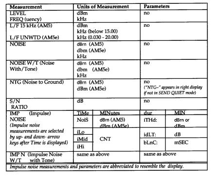
6.7.1 General Description of Impulse Noise Measurement . . . . . . |
6 ñ 8 |
|
|
NOTE . . . . . . . . . . . . . . . . . . . . . . . . . . . . . . . . . . . . . . . . . |
6 ñ 8 |
|
NOTE . . . . . . . . . . . . . . . . . . . . . . . . . . . . . . . . . . . . . . . . . |
6 ñ 9 |
6.7.2 |
Impulse Noise Measurements, Parameters, and Procedure . |
6 ñ 9 |
|
NOTE . . . . . . . . . . . . . . . . . . . . . . . . . . . . . . . . . . . . . . . . . |
6 ñ 9 |
6.7.3 Evaluation of Measurement Data . . . . . . . . . . . . . . . . . . . . . . . |
6ñ12 |
|
6.7.4 Test Setup for Impulse Noise without Tone . . . . . . . . . . . . . . |
6ñ14 |
|
6.7.5 Test Setup for Impulse Noise with Tone . . . . . . . . . . . . . . . . . |
6ñ14 |
|
6.7.6 |
Noise Weighting Filters . . . . . . . . . . . . . . . . . . . . . . . . . . . . . . . |
6ñ14 |
November 19, 1997 |
viii |
AM5(e) Classic Instruction Manual |
(18-0047) |
TABLE OF CONTENTS |
||||
SECTION 7 ó IEEE NOISE WEIGHTING FILTERS FOR AM5 CLASSIC . . . . |
7 |
ñ 1 |
||||
|
|
NOTE . . . . . |
. . . . . . . . . . . . . . . . . . . |
. . . . . . . . . . . . . . . . . |
7 |
ñ 1 |
7.1 |
NOISE WEIGHTING FILTERS . . . . . . . . . . . . . . . |
. . . . . . . . . . . . . . . . |
7 |
ñ 1 |
||
7.2 |
60 Hz FILTER . . . . . . . . . . . |
. . . . . . . . . . . . . . . . . . . |
. . . . . . . . . . . . . . . . |
7 |
ñ 8 |
|
7.3 |
L/F 15 kHz MEASURE FILTER . . . . . . . . . . . . . . |
. . . . . . . . . . . . . . . . |
7 |
ñ 8 |
||
|
|
NOTE . . . . . . |
. . . . . . . . . . . . . . . . . . . |
. . . . . . . . . . . . . . . . |
7 |
ñ 8 |
SECTION 8 ó CCITT NOISE WEIGHTING FILTERS FOR AM5e CLASSIC |
8 |
ñ 1 |
||||
|
|
NOTE . . . . . . |
. . . . . . . . . . . . . . . . . . . |
. . . . . . . . . . . . . . . . |
8 |
ñ 1 |
8.1 |
NOISE WEIGHTING FILTERS . . . . . . . . . . . . . . . |
. . . . . . . . . . . . . . . . |
8 |
ñ 1 |
||
8.2 |
60 Hz FILTER . . . . . . . . . . . |
. . . . . . . . . . . . . . . . . . . |
. . . . . . . . . . . . . . . . |
8 |
ñ 7 |
|
8.3 |
L/F UNWTD MEASURE FILTER . . . . . . . . . . . . . |
. . . . . . . . . . . . . . . . |
8 |
ñ 7 |
||
|
|
NOTE . . . . . . |
. . . . . . . . . . . . . . . . . . . |
. . . . . . . . . . . . . . . . |
8 |
ñ 7 |
SECTION 9 ó SEND FUNCTIONS AND PARAMETERS . . |
. . . . . . . . . . . . . . . . |
9 |
ñ 1 |
|||
9.1 |
NO-SIGNAL, TERMINATED (QUIET) . . . . . . |
. . . . . . . . . . . . . . . . |
9 |
ñ 2 |
||
|
|
CAUTION: . . . . . . . |
. . . . . . . . . . . . . . . . . . . |
. . . . . . . . . . . . . . . . |
9 |
ñ 2 |
|
9.1.1 |
QUIET Data . . . . . . |
. . . . . . . . . . . . . . . . . . . |
. . . . . . . . . . . . . . . . |
9 |
ñ 2 |
|
9.1.2 |
QUIET Parameters: |
. . . . . . . . . . . . . . . . . . . |
. . . . . . . . . . . . . . . . |
9 |
ñ 2 |
9.2 |
1004 Hz TONE (1004 Hz) . |
. . . . . . . . . . . . . . . . . . . |
. . . . . . . . . . . . . . . . |
9 |
ñ 3 |
|
|
9.2.1 1004 Hz Data Display . . . . . . . . . . . . . . . . . |
. . . . . . . . . . . . . . . . |
9 |
ñ 4 |
||
|
9.2.2 1004 Hz Parameter Display/Adjustment |
. . . . . . . . . . . . . . . . |
9 |
ñ 4 |
||
9.3 |
VARIABLE FREQUENCY GENERATOR (VAR Hz) . . . . . . . . . . |
9 |
ñ 4 |
|||
|
9.3.1 VAR Hz Data Display . . . . . . . . . . . . . . . . . |
. . . . . . . . . . . . . . . . |
9 |
ñ 4 |
||
|
9.3.2 VAR Hz Parameter Display/Adjustment |
. . . . . . . . . . . . . . . . |
9 |
ñ 4 |
||
|
|
NOTE . . . . . . |
. . . . . . . . . . . . . . . . . . . |
. . . . . . . . . . . . . . . . |
9 |
ñ 4 |
9.4 |
SWEEP GENERATOR (SWEEP) . . . . . . . . . . . . . . |
. . . . . . . . . . . . . . . . |
9 |
ñ 6 |
||
|
9.4.1 |
SWEEP Data Display . . . . . . . . . . . . . . . . . |
. . . . . . . . . . . . . . . . |
9 |
ñ 6 |
|
|
9.4.2 |
SWEEP Parameter Display/Adjustment . |
. . . . . . . . . . . . . . . . |
9 |
ñ 6 |
|
|
|
NOTE . . . . . . |
. . . . . . . . . . . . . . . . . . . |
. . . . . . . . . . . . . . . . |
9 |
ñ 6 |
9.5 |
SIGNALLING FREQUENCY SKIP (SF SKIP) . . |
. . . . . . . . . . . . . . . . |
9 |
ñ 8 |
||
|
9.5.1 SF SKIP Rejection for AM5 Classic . . . . . . |
. . . . . . . . . . . . . . . . |
9 |
ñ 8 |
||
|
9.5.2 SF SKIP Rejection for AM5e Classic . . . . . |
. . . . . . . . . . . . . . . . |
9 |
ñ 8 |
||
9.6 |
SINGLE FREQUENCY TONES: (F1, F2, F3, F4) . |
. . . . . . . . . . . . . . . . |
9 |
ñ 8 |
||
|
9.6.1 |
General Information . . . . . . . . . . . . . . . . . . |
. . . . . . . . . . . . . . . . |
9 |
ñ 8 |
|
|
9.6.2 |
Loop Back Tone . . . |
. . . . . . . . . . . . . . . . . . . |
. . . . . . . . . . . . . . . . |
9 |
ñ 9 |
9.7 |
OPEN CIRCUIT . . . . . . . . . |
. . . . . . . . . . . . . . . . . . . |
. . . . . . . . . . . . . . . . |
9 |
ñ 9 |
|
SECTION 10 ó AM5 and AM5E CLASSIC SPECIFICATIONS . . . . . . . . . . . . |
10 |
ñ 1 |
||||
SECTION 11 ó WARRANTY, CALIBRATION, AND SERVICE . . . . . . . . . . |
11 |
ñ 1 |
||||
11.1 WARRANTY . . . . . . . . . . . . . |
. . . . . . . . . . . . . . . . . . . |
. . . . . . . . . . . . . . . |
11 |
ñ 1 |
||
11.2 SERVICE POLICY . . . . . . . . |
. . . . . . . . . . . . . . . . . . . |
. . . . . . . . . . . . . . . |
11 |
ñ 1 |
||
11.3 CALIBRATION POLICY . . . |
. . . . . . . . . . . . . . . . . . . |
. . . . . . . . . . . . . . . |
11 |
ñ 1 |
||
11.4 RETURN OF UNIT . . . . . . . . |
. . . . . . . . . . . . . . . . . . . |
. . . . . . . . . . . . . . . |
11 |
ñ 2 |
||
SECTION A1 ó APPENDIX . . . . . . . . . |
. . . . . . . . . . . . . . . . . . . |
. . . . . . . . . . . . . . . |
A1 |
ñ 1 |
||
A.1.1 SCOPE . . . . . . . . . . . . . . . . . |
. . . . . . . . . . . . . . . . . . . |
. . . . . . . . . . . . . . . |
A1 |
ñ 1 |
||
A.1.2 EQUIPMENT REQUIRED |
. . . . . . . . . . . . . . . . . . . |
. . . . . . . . . . . . . . . |
A1 |
ñ 1 |
||
November 19, 1997 |
|
ix |
|
|
|
|
AM5(e) Classic Instruction Manual |
(18-0047) |
TABLE OF CONTENTS |
|
A.1.3 CALIBRATION PROCEDURE . . . . . . . . . . . . . . . |
. . . . . . . . . . . . . . . . A1 |
ñ 1 |
|
A.1.4 VALIDATION PROCEDURE . . . . . . . . . . . . . . . . . |
. . . . . . . . . . . . . . . A1 |
ñ 3 |
|
INDEX . . . . . . . . . . . . . . . . . . . . . . . . . . . . |
. . . . . . . . . . . . . . . . . . . . |
. . . . . . . . . . . . . . . . I ñ 1 |
|
November 19, 1997 |
x |
AM5(e) Classic Instruction Manual |
(18-0047) |
TABLE OF CONTENTS |
|
LIST OF ILLUSTRATIONS |
|
||
Figure 1 ó Wrong (way to wind power cable) . . . . . . |
INSIDE OF FRONT COVER |
||
Figure 2 ó Correct (way to wind power cable) . . . . . |
INSIDE OF FRONT COVER |
||
Figure 3-1 ó AM5 Classic Front Panel |
. . . . . . . . . . . . . . . |
. . . . . . . . . . . . . . . . . . . . . |
3 ñ 2 |
Figure 3-2 ó AM5e Classic Front Panel |
. . . . . . . . . . . . . . . |
. . . . . . . . . . . . . . . . . . . . |
3 ñ 2 |
Figure 3-3 ó Level (dB/dBm) and Noise (dBrn ) Units of Measurement . . . . . . . |
3 ñ 7 |
||
Figure 3-4 ó AM5(e) Classic Rear Panel Drawing . . . . . . . |
. . . . . . . . . . . . . . . . . . . . |
3ñ16 |
|
Figure 5-1 ó Line Cable Accessories for AM5(e) Classic . |
. . . . . . . . . . . . . . . . . . . . |
5 ñ 1 |
|
Figure 5ñ2 ó 4-Wire Line Circuit Block Diagram . . . . . . . . |
. . . . . . . . . . . . . . . . . . . . |
5 ñ 2 |
|
Figure 5ñ3 ó 2ñWire Line Circuit Block Diagram . . . . . . . |
. . . . . . . . . . . . . . . . . . . . |
5 ñ 3 |
|
Figure 5-4 ó 4-Wire End-to-End Testing Configuration . |
. . . . . . . . . . . . . . . . . . . . |
5 ñ 8 |
|
Figure 5-5 ñ 4-Wire Testing with Responder . . . . . . . . . . . |
. . . . . . . . . . . . . . . . . . . . |
5ñ11 |
|
Figure 5-6 ó 2-Wire Testing with Responders . . . . . . . . . . |
. . . . . . . . . . . . . . . . . . . . |
5ñ11 |
|
Figure 6ñ1 ó Impulse Noise Measurement Selection/Displays . . . . . . . . . . . . . . . |
6ñ10 |
||
Figure 6ñ2 ó Impulse Noise Parameters Selection/Display . . . . . . . . . . . . . . . . . . |
6ñ11 |
||
Figure 6ñ3 ó Illustration of Impulse Noise Measurement |
. . . . . . . . . . . . . . . . . . . . |
6ñ13 |
|
Figure 7-1 ó CMSG Bandwidth Filter (CMSG) . . . . . . . . . |
. . . . . . . . . . . . . . . . . . . . |
7 ñ 2 |
|
Figure 7ñ2 ó Program Bandpass Filter (PGM) . . . . . . . . . . |
. . . . . . . . . . . . . . . . . . . . |
7 ñ 3 |
|
Figure 7ñ3 ó 3 kHz Low Pass Filter (3 kHz) . . . . . . . . . . . . |
. . . . . . . . . . . . . . . . . . . . |
7 ñ 4 |
|
Figure 7ñ4 ó 15 kHz Low Pass Filter (15 kHz) . . . . . . . . . |
. . . . . . . . . . . . . . . . . . . . |
7 ñ 5 |
|
Figure 7ñ5 ó 50 Kilobit Filter (50 kBit) . |
. . . . . . . . . . . . . . . |
. . . . . . . . . . . . . . . . . . . . |
7 ñ 6 |
Figure 7ñ6 ó Wideband 120 kHz Filter (WIDE óAM5-120 Model . . . . . . . . . . . . |
7 ñ 7 |
||
Figure 7ñ7 ó Wideband 160 kHz Filter (WIDE ó AM5-200 Model) . . . . . . . . . . . |
7 ñ 7 |
||
Figure 8-1 ó Psophometric Filter (PSHO) . . . . . . . . . . . . . . |
. . . . . . . . . . . . . . . . . . . . |
8 ñ 2 |
|
Figure 8ñ2 ó Sound Unweighted Filter (UNWTD Q-PEAK/UNWTD RMS) . . . . |
8 ñ 3 |
||
Figure 8ñ3 ó Sound Weighted Filter (SWTD Q-PEAK/SWTD RMS) . . . . . . . . . . |
8 ñ 4 |
||
Figure 8-4 ó 2 kHz Flat Filter (2 kHz FLAT) . . . . . . . . . . . |
. . . . . . . . . . . . . . . . . . . . |
8 ñ 5 |
|
Figure 8ñ5 ó Wideband 120 kHz Filter (WIDE óAM5e-120 Model) . . . . . . . . . . . |
8 ñ 6 |
||
Figure 8ñ6 ó Wideband 160 kHz Filter (WIDE ó AM5e-200 Model) . . . . . . . . . . |
8 ñ 6 |
||
Figure 9ñ1 ó Send QUIET Data Display . . . . . . . . . . . . . . . . . . . . . . . . . . . . . . . . . . . 9 ñ 2 Figure 9ñ2 ó Send QUIET Parameter Displays . . . . . . . . . . . . . . . . . . . . . . . . . . . . . 9 ñ 3 Figure 9ñ3 ó Send 1004 Hz Data and Parameter Displays . . . . . . . . . . . . . . . . . . . 9 ñ 5 Figure 9ñ4 ó Send VARiable Hz Data and Parameter Displays . . . . . . . . . . . . . . . 9 ñ 5 Figure 9ñ5 ó Send SWEEP Data and Parameter Display . . . . . . . . . . . . . . . . . . . . . 9 ñ 7
November 19, 1997 |
xi |
AM5(e) Classic Instruction Manual |
(18-0047) |
OVERVIEW/UNPACKING |
1.OVERVIEW AND UNPACKING
1.1OVERVIEW
This Instruction Manual describes the operation of the Ameritec Model AM5 Classic and AM5e Classic Voice/Data Transmission Test Sets.
The AM5 Classic and AM5e Classic are microprocessor-based test instruments used to make Transmission Impairment Measurements (ìTIMSî) on 2- and 4-wire circuits. Models are available for IEEE Standards and CCITT Recommendations as follows:
AM5 |
- - -CLASSIC-120 |
IEEE Standard 743-1984 (Bell Standard 41009) |
AM5 |
CLASSIC-200 - - - |
Same as AM5 Classic-120 with extended range to 200 kHz |
AM5e |
CLASSIC-120 - - - |
CCITT International Recommendations |
AM5e |
CLASSIC-200 - - - |
Same as AM5e Classic-120 with extended range to 200 kHz |
Both the AM5 Classic and AM5e Classic are hereafter referred to as ìAM5(e) Classicî, and except where specified ìAM5î or ìAM5eî all information applies to both types of Classics.
The AM5(e) Classic also contains a separate full-function test tone generator which produces operator-selected and automatically-stepped (sweep) tones from 20 Hz to 120 kHz (or 200 kHz) required for tests.
The AM5(e) Classic provides five (5) impedance selections for RX and TX lines, separate DC hold circuits, and a built-in speaker monitor.
Optional features include a Signaling Adapter with Ring Generator, ìSiemensî-type Line Test Connections, Rechargeable batteries for cordless portable operation, a snapon cover, and a rack-mounting kit for permanent installations.
The 200 kHz Model of both the AM5 Classic and AM5e Classic extends the maximum frequency response measurement and generation from 120 kHz to 200 kHz.
1.2UNPACKING
The AM5(e) Classic was thoroughly tested and carefully packed before shipment, and was in good condition when given to the carrier for shipment.
Upon receipt, thoroughly inspect the outside of the shipping container for damage. If damage is noted, immediately contact the carrier. The name of the carrier will be noted on the packing slip which is attached to the outside of the shipping container.
Open the container carefully and compare the contents with the packing slip. Note any damage or shortages. Notify the carrier in the event of damage. Notify Ameritec in the event of shortages.
Save the shipping container for future use in case the AM5(e) Classic must be returned to the factory.
November 19, 1997 |
Page 1-2 |
AM5(e) Classic Instruction Manual |
(18-0047) |
POWER CONSIDERATIONS |
2.POWER CONSIDERATIONS
2.1COMMERCIAL POWER
CAUTION: Before connecting the AM5(e) Classic to AC Power , be sure that the AC power selector switch is in the correct position. For more details refer to Section 3, sub-sections 3.3.1. and 3.4.1.
All models of the AM5(e) Classic are powered from commercial 115 V AC or 230 V AC 50/60 Hz power, and have a power consumption of 26 Watts (VA). A rear-panel selector switch selects 115 V AC or 230 V AC.
A detachable 3-wire power cord is furnished which mates with a CCE standard V-type connector on the rear panel. The other end of the power cord has a standard threeconductor AC plug. A replaceable 1/2 Ampere fuse is also accessible on the rear panel.
2.2OPTIONAL BATTERY PACK
The AM5(e) Classic may be equipped with an internal battery pack to allow for full cordless (no commercial power) operation.
The battery pack consists of two sealed lead-acid batteries and associated charging circuitry. When fully charged, the batteries will power the AM5(e) Classic for about five to eight (5-8) hours.
A low battery is indicated by blinking decimal points on the front panel display. Blinking decimal points indicate about one-half hour of remaining battery power before recharging is required.
The AM5(e) Classic may be operated while the batteries are recharging. Recharging occurs continuously whenever the AM5(e) Classic is plugged into AC power whether the power switch is turned ON or OFF. However, charging will be accomplished faster when the power switch is turned OFF. Commercial power interruption will not cause unit to stop operating as long as the batteries remain charged.
2.3POWER ON AND OFF
The power ON-OFF switch is located on the upper right side of the front panel (refer to Section 3 for illustration). It is an alternate-action push button. When pushed-in, it will lock in that position and the power is ON. Push it again, the button will pop out, and the power is OFF. When the power is turned ON, the AM5(e) Classic will go through a self-test procedure, then will show factory-set test selections referred to as ìdefaultsî. The operator usually will change these settings for a particular test configuration.
The AM5(e) Classic is equipped with a non-volatile memory for test setups. Although loss of power will cause operation to cease, current test parameter settings will be
stored in memory. When the AM5(e) Classic is turned back ON, these settings can be re-established instead of the defaults. A procedure for restoring these settings when power is turned ON is described in Section 4 of this Manual.
November 19, 1997 |
Page 2-1 |
AM5(e) Classic Instruction Manual |
(18-0047) |
DESCRIPTION |
3.PHYSICAL AND FUNCTIONAL DESCRIPTION
This section describes the general physical characteristics of the AM5(e) Classic, the Front and Rear Panel controls, indicators, and connectors, and the optional equipment.
3.1PHYSICAL CHARACTERISTICS
3.1.1Weight: The AM5(e) Classic weighs six (6) pounds (2.7 kilograms) without the optional battery pack, and 10 pounds (4.5 kilograms) with the battery pack.
3.1.2Portable Dimensions: The AM5(e) Classic in its portable case measures 8.3 in. (210 mm) wide, 3.5 in. (89 mm) high, and 12.1 in. (307 mm) deep. With the optional snap-on cover in place, the Classic is 14 in. (356 mm) deep.
3.1.3Rack Mounted Dimensions: A 19 in. Rack Mount kit (P/N 850076) can be ordered for fixed installations. When mounted in the Rack Mount kit, the AM5(e) Classic measures 19 in (483 mm) wide, 3.5 in. (89 mm) high, and 12.1 in. (307 mm) deep. A Rack Mount kit shelf is also available (P/N 850233). For more detail refer to sub-section 3.6.5.
3.1.4Construction: The front panel (with switch and indicators labels appropriate for the AM5 Classic or AM5e Classic ) and a black, steel rear panel are attached to a sturdy aluminum case. Within the case, electronic components are mounted on three plug-in printed circuit boards, interconnected with ribbon cables. The AC power supply and optional battery pack with charging circuitry are also contained within the case.
CAUTION: None of the electronic components within the case are userserviceable, and opening the case will void the manufacturer’s warranty.
3.1.5Rubber Feet: There are four (4) rubber feet on the bottom of the case, and two rear-panel support brackets for positioning the AM5(e) Classic horizontally or vertically during operation. There are also four (4) rubber feet on the left side for setting it down after carrying it with the carrying handle.
3.1.6Carrying Handle: The carrying handle is made of thick, soft, flexible
plastic. It is located on the right side of the case. It extends for use and retracts against the case when not in use.
NOTE: Neither the rubber feet nor the carrying handle are provided when the AM5(e) Classic is installed in the 19 inch Rack Mount kit (P/N 850076).
3.2FRONT PANEL DESCRIPTION
The front panel measures approximately 3 in. (75 mm) high by 8 in. (205 mm) wide. Both panels are illustrated in Figures 3-1 and 3-2. The panels are similar in appearance with the exception of the label nomenclature for filters, certain noise measurements, and DIAL terminal identification.
November 19, 1997 |
Page 3-1 |
AM5(e) Classic Instruction Manual |
(18-0047) |
DESCRIPTION |
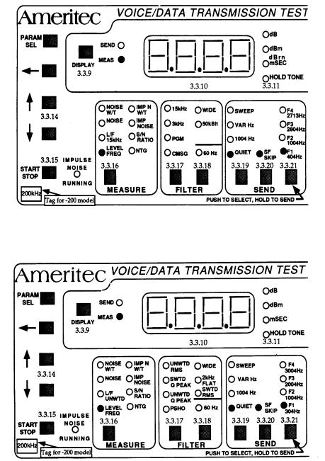
Figure 3-1 — AM5 Classic Front Panel (Sheet 1 of 2)
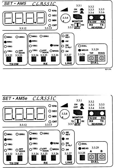
Figure 3-2 — AM5e Classic Front Panel (Sheet 1 of 2)
November 19, 1997 |
Page 3-2 |
AM5(e) Classic Instruction Manual |
(18-0047) |
DESCRIPTION |
Figure 3-1 — AM5 Classic Front Panel (Sheet 2 of 2)
Figure 3-2 — AM5e Classic Front Panel (Sheet 2 of 2)
November 19, 1997 |
Page 3-3 |

AM5(e) Classic Instruction Manual |
(18-0047) |
DESCRIPTION |
For the AM5(e) Classic models that have extended frequency response, the following designation plate appears on the lower-left side of the panel:
200 kHz
The front panel contains push-button switches, LED indicators, and LED displays for setting test conditions and displaying measurements. A speaker volume control knob is also located on the front panel. Bantam jacks are provided for line connections (duplicated on the rear panel as terminals) and two terminals are provided for a user’s “Butt Set” to allow dialing and talking by the user.
All push button keys are non-membrane type, and offer good visual, tactile, and audible feedback. All indicators, including the display, are LEDs and should never need replacement.
The remaining sub-sections in Section 3 describe the controls, indicators, and displays on the front panel. The numbering of the sub-sections corresponds with the identifications of sub-sections shown on Figures 3-1 and 3-2.
Further descriptions are contained in the other Sections of this manual which describe :
• |
Self Test Operations |
Section 4 |
• |
Line Test Connections and Configurations |
Section 5 |
• |
Measure Functions and Parameters |
Section 6 |
• |
Filters for AM5 Classic |
Section 7 |
• |
Filters for AM5e Classic |
Section 8 |
• |
Send Functions and Parameters |
Section 9 |
November 19, 1997 |
Page 3-4 |

AM5(e) Classic Instruction Manual |
(18-0047) |
DESCRIPTION |
3.3.1ON OFF Button (power switch):
CAUTION: Before connecting the AM5(e) Classic to AC Power , be sure that the selector switch is in the correct position. For more details refer to 3.4.1.
Push the button IN to turn power ON. Push the button again and the button will pop out to turn power OFF. The front panel illustrates the power positions as shown below:
Button in |
|
|
|
Power |
ON |
|
|
|
|||
|
|
|
|
||
|
|
|
|
|
|
Button out |
|
|
|
Power |
OFF |
When the power is turned ON, The Red LED indicators will come on to show the default conditions. The two display windows also may show red characters. For more information on default settings, refer to Section 4.
NOTE: The functions selected for the TX/2W jack described in the next three sub-sections are duplicated by the T and R terminals on the rear panel.
3.3.2TX/2W bantam jack for 2-wire circuits (2W LED on): The Classic both transmits and receives signals over this jack through a built-in hybrid circuit. Connect a 2- wire circuit to this jack.
3.3.3TX/2W bantam jack for 4-wire circuits (4W LED on): The Classic transmits signals over this jack. Connect the send (transmit, or TX) pair of a four-wire circuit to this jack.
3.3.4TX/2W bantam jack for REVERSE selection (4W REV LED on): This jack becomes a receive (RX) jack as shown on the panel. The Classic receives signals over this jack (as described in 3.3.5). Connections are per test requirements.
NOTE: The functions selected for the RX jack described in the next two sub-sections are duplicated by the T1 and R1 terminals on the rear panel.
3.3.5RX bantam jack for 4-wire circuits (4W LED on): The Classic receives signals over this jack. Connect the receive (or RX) pair of a four-wire circuit to this jack.
3.3.6RX bantam jack for 4-wire circuits for REVERSE selection (4W REV LED on):
The jack becomes a transmit (TX) jack as shown on the panel. The Classic transmits signals over this jack (as described in 3.3.3). Connections are per test requirements.
November 19, 1997 |
Page 3-5 |
AM5(e) Classic Instruction Manual |
(18-0047) |
DESCRIPTION |
3.3.7MONITOR (TX, MEAS, RX) switch: This three position switch selects the circuit point where the internal amplifier/speaker is connected:
3.3.8Speaker Volume Control: After the MONITOR switch has been used to select the monitor point, the Volume control can be turned clockwise to increase the speaker volume and counter-clockwise to decrease the volume.
NOTE: The speaker is located at the top of the unit near the front.
3.3.9DISPLAY Key: This key selects whether the data shown in the left-hand and right-hand display windows represent test signals sent to a circuit under test (SEND) or test data measurements on the circuit under test (MEAS). Each time the key is pressed, the SEND or MEAS(ure) LED will come on to indicate which function has been selected.
3.3.10Left-Hand 7-Segment Display: This is a red LED display containing four 7- segment characters with floating decimal point. These characters will indicate Levels for the SEND or MEASURE Selections in accordance with the LED indicators to the right of the display (except for Impulse Noise measurements where they identify the value being displayed in the right-hand 7-Segment Display).
After the PARAM SEL key is pressed, the characters identify a parameter that may be set in the right-hand LED display (for those functions that have parameters). Parameters for MEAS and SEND functions are described in Sections 6 and 9, respectively.
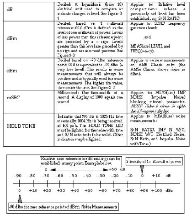
3.3.11Left-Hand LED’s (dB, dBm, dBrn, mSEC, HOLD TONE): These LEDs provide units of measurement and other information about the current SEND or MEAS(ure) DISPLAY selection. Refer to the table on the next page:
November 19, 1997 |
Page 3-6 |
AM5(e) Classic Instruction Manual |
(18-0047) |
DESCRIPTION |
Figure 3-3 - Level (db/dbm) and Noise (dBrn) Units of measurement
November 19, 1997 Page 3-7
AM5(e) Classic Instruction Manual |
(18-0047) |
DESCRIPTION |
3.1.7Right-Hand 7-Segment Display: This is a red LED display containing four 7-segment characters with floating decimal point display. These characters will indicate values for the SEND or MEASURE frequency, time, or impulse noise count selections in accordance with the LED indicators to the right of the display (Refer to 3.3.13). When setting parameters, the numeric value of the parameter identified in the left-hand display is shown.
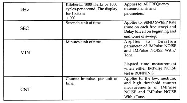
3.1.8Units of Measurement LED’s (kHz, SEC, MIN, CNT): These LEDs provide the units of measurement that apply to the data displayed in the right-hand 7-Segment Display for the SEND or MEAS(ure) DISPLAY selection.
3.1.9PARAM SEL keys (Parameter Select and arrow keys): The PARAM SEL key is used to step through parameters which may be pre-set for certain of the SEND or MEAS(ure) functions (Refer to Sections 6 and 9). The table that follows explains the functions of these keys.
NOTE: The key labelled START STOP, and the LED labelled IMPULSE NOISE RUNNING are not related to parameter selection or entry (see 3.3.15)
November 19, 1997 |
Page 3-8 |

AM5(e) Classic Instruction Manual |
(18-0047) |
DESCRIPTION |
November 19, 1997 |
Page 3-9 |
AM5(e) Classic Instruction Manual |
(18-0047) |
DESCRIPTION |
3.3.15START/STOP Key (Impulse Noise Measurement): This key is pressed to start Impulse Noise measurements after IMP NOISE has been selected in the MEASURE area of the panel. (see 3.3.16).
When Impulse Noise measurements are running the IMPULSE NOISE RUNNING indicator beside the switch flashes. Impulse Noise measurements may be set (through parameters) to have a time duration, so after the test is started it will stop after the time has elapsed. To stop Impulse Noise measurements while the indicator is flashing, press the START/STOP key again. Refer to Section 6 for a description of Impulse Noise measurement.
3.1.10MEASURE Key: Eight types of measurement may be selected by this key. Selection is by rotation and is indicated by the lighting of the LED adjacent to the abbreviation for the measurement. Measurements are always made from a signal source coming into the AM5(e) Classic (RX for 4-wire lines, or TX/2W for 2-wire lines). The following table identifies the measurements, indicates units of measurement, and whether there are parameters. MEASURE functions and parameters are described in Section 6.
November 19, 1997 |
Page 3-10 |
AM5(e) Classic Instruction Manual |
(18-0047) |
DESCRIPTION |
3.3.17FILTER (left key): This key can select six filters and RMS detection for use with the MEASURE NOISE functions of an AM5 Classic (as shown in Figure 3- 1) and five filters and RMS or Quasi-Peak detectors for an AM5e Classic (shown in Figure 3-2). Filters are selected in rotation each time the key is pressed, and the selection is indicated by the lighting of the LED adjacent to the abbreviation for the measurement.
For the AM5 Classic the selections are:
• |
CMSG |
(C-Message Bandpass) |
|
• |
PGM |
(Program Bandpass) |
|
• |
3 KHz |
(3 kHz flat) |
|
• |
15kHz |
(15 kHz flat) |
|
• |
50kBit |
(Low Pass and High Pass) |
|
• |
WIDE |
(20 |
Hz to 120 kHz) for standard units or |
|
|
(20 |
Hz to 160 kHz) for 200 kHz units |
For the AM5e Classic the selections are:
• PSHO |
(Psophometric Bandpass) |
•UNWTD Q PEAK (Sound Unweighted Quasi-Peak detection)
•SWTD Q PEAK (Sound Weighted Quasi-Peak detection)
•UNWTD RMS (Sound Unweighted RMS detection)
• |
SWTD RMS |
(Sound Weighted RMS detection) |
|
• |
2kHz FLAT |
(2 kHz flat) |
|
• |
WIDE |
(20 |
Hz to 120 kHz) for standard units or |
|
|
(20 |
Hz to 160 kHz) for 200 kHz units |
NOTE: When MEASURE selection is LEVEL/FREQ or L/F 15 kHz on an AM5 Classic (LEVEL/FREQ or L/F UNWTD for AM5e Classic), none of the above filters can be selected. However, the L/F 15 kHz (L/F UNWTD) selection places a low pass filter into the measurement circuits to eliminate high frequencies which are not of interest or when high-frequency signals (in addition to Voice Frequencies) on the line could give false readings. Filters are described in detail in Section 7 for the AM5 Classic, and in Section 8 for the AM5e Classic.
3.3.18 FILTER (right key): This key selects a 60 Hz filter; the 60 Hz LED is lighted when the filter is selected. The 60 Hz filter can be selected in addition to any other filters, and is useful when making measurements on circuits that have power-line interference. This filter cuts off frequencies below 60 Hz, and so also applies to 50 Hz or 25 Hz power-line interference. If the LEVEL or FREQuency measurement display is not steady, there may be an improvement when this function is ON.
•OFF (LED not lighted) is the default.
November 19, 1997 |
Page 3-11 |
AM5(e) Classic Instruction Manual |
(18-0047) |
DESCRIPTION |
3.3.19SEND (left key): This key allows the user to select and activate, in rotation,
• |
QUIET |
no output |
• |
1004 Hz |
steady tone |
• |
VAR Hz |
Variable frequency tone (manually adjustable over the |
|
|
entire frequency range of the generator) |
• |
SWEEP |
Sweep frequency generator which may be adjusted by |
|
|
parameters for lower limit (STrT), upper limit (SToP), |
|
|
frequency increment (STEP), time on each frequency |
|
|
(rATE) and dwell time on the first and last frequencies |
|
|
(dLAY). |
When a new function is selected, the LED is lighted immediately, the previously selected SEND function stops, and the new function starts.
•QUIET is the default.
3.3.20SEND (middle key): The middle key activates SF SKIP, and the LED is lighted when this function is turned ON. SF skip prevents any tones from being sent in the SF signaling range (2450 - 2750 Hz for AM5 Classic; 2130 - 2430 Hz for AM5e Classic). This skip prevents interference with other equipment while making tests.
•ON (SF SKIP lighted) is the default.
3.3.21SEND (right key): This key selects and sends one of four frequencies (each of which may be manually adjusted from the nominal frequencies stamped on the panel by parameters).
To select a frequency, press the key momentarily (less than one second) to step, in rotation, from F1 to F4. The LED adjacent to the frequency flashes on and off at 1/2 second intervals to show the frequency is selected.
To send the frequency, press and hold the key for approximately three seconds until the LED goes steady, then release the key. The tone will be sent until the key is pressed again (for less than one second), or if a frequency is selected from the SEND (left key) function.
The single-tone over-rides any other SEND function. If a SWEEP frequency is being generated, the SWEEP is reset to its starting frequency after the tone is stopped.
The single-tone may also be over-ridden by pressing any of the left SEND keys. For example, if an F4 tone is being output, shifting from QUIET to 1004 Hz will automatically stop the F4 tone and send the 1004 Hz tone.
•F1 is the default.
NOTE: Send Functions and Parameters are described in Section 9.
November 19, 1997 |
Page 3-12 |
AM5(e) Classic Instruction Manual |
(18-0047) |
DESCRIPTION |
3.3.22TX/2W (left key): This key selects, in rotation, the impedance of the output of the AM5(e) Classic SEND functions at the TX/2W jack (and rear-panel T and R terminals) when the LINE selector (3.3.27) is set for any position but 4W REV(erse).
When in the LINE selector is in 4W REVerse position, the selected impedance is for output at the TX REVERSE jack (and rear-panel T1 and R1 terminals).
•600 ohm is the default.
3.3.23TX/2W (right key): This key is an alternate-action key which connects a holding coil equivalent (DC path of about 200Ω) to the TX/2W circuit while maintaining an AC impedance of greater than 50 KΩ.. When OFF HOOK, the holding coil is across the TX/2W tip and ring terminals. When ON HOOK, the holding coil is disconnected.
•ON HOOK (OFF HOOK not lighted) is the default.
3.3.24RX (left key): This key selects, in rotation, the impedance of the input of the AM5(e) Classic for MEASURE functions at the RX (and rear-panel T1 and R1 terminals) when the LINE selector (3.3.27) is set to 4W.
When the LINE selector is in 4W REVerse position, the selected impedance is for input at the RX REVERSE jack (and rear-panel T and R terminals).
When the LINE selector is in either 2W position, the measure section presents highimpedance (> 50 KΩ) to the TX/2W jack.
•600 ohm is the default.
The TERMinating function must be active for any impedance setting to apply (see sub-section 3.3.26).
3.3.25RX (middle key): This key is an alternate-action key which connects a holding coil equivalent (DC path of about 200Ω) to the RX circuit while maintaining an AC impedance of greater than 50 KΩ.. When OFF HOOK, the holding coil is across the RX tip and ring terminals. When ON HOOK, the holding coil is disconnected.
•ON HOOK (OFF HOOK not lighted) is the default.
3.3.26RX right key): This key selects, in rotation, a termination with the selected impedance (TERMinate lighted) or a high-impedance (> 50 KΩ) bridging impedance (BRDG lighted). This key has no effect on RX functions when the LINE selector is in a 2W position.
•TERMinate is the default.
November 19, 1997 |
Page 3-13 |
AM5(e) Classic Instruction Manual |
(18-0047) |
DESCRIPTION |
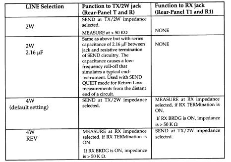
3.3.27LINE Key: This key selects, in rotation, the line connections for the TX/2W and RX jacks. Selections are shown in the following table. Descriptions of the physical connections to the jacks are provided in Section 5.
3.3.28DIAL key: This key selects, in rotation, the DIAL and MEAS(ure) functions. When DIAL is selected, the TX/2W jack is directly connected to the DIAL terminals on the front panel and all internal AM5(e) Classic circuitry is disconnected.
When MEAS(ure) is selected, the DIAL terminals are disconnected and the internal AM5(e) Classic circuitry is connected.
• MEAS(ure) is the default.
3.3.29DIAL Terminals: The DIAL terminals permit you to connect a Lineman’s Handset (also called a “butt set”) to the terminals labelled “TIP” and “RING” on the AM5 Classic or “A” and ”B” on the AM5(e) Classic.
When the DIAL function has been selected, you can use the Lineman’s Handset to dial out on the TX/2W connection (either DTMF or MF) to access a test line, responder, or other location. For pulse dialing, you must set the unit to either 4W (or 4W REVerse with change to the RX connection). This applies to units with software version 103A and before (refer to 4.6.3, step 3, to determine software used in the unit.).
After the connection is established, select MEAS(ure) to conduct the test.
November 19, 1997 |
Page 3-14 |
AM5(e) Classic Instruction Manual |
(18-0047) |
DESCRIPTION |
3.4REAR PANEL
The rear panel of the AM5(e) Classic is shown in Figure 3-4. The AC power supply assembly is mounted on the right side of the rear panel. It has a CCE standard V-type connector for the power cord, a fuse holder for the replaceable 1/2 Ampere fuse, and a selector switch for 115 V AC or 230 V AC.operation.
CAUTION: Before connecting the Classic to AC Power be sure that the AC Power selector switch is in the correct position. For more details refer to 3.4.1.
There are five terminals on the lower left side of the rear panel for “permanent” connections to a line (especially when the AM5(e) Classic is rack mounted).
NOTE: the REVERSE switch on the front panel reverses the functions of both the front-panel jacks and the rear-panel terminals.
3.4.1AC Power Selector Switch: This is a red slide switch that is located on the top of the Power supply. It is used to select between 115 Volt and 230 Volt operation. Before plugging in the power cord, set this switch to match the power source to which the power cord is to be connected.
CAUTION: Observe the CAUTION notice printed on the back of the AM5(e) Classic. When planning to connect the power cord to a 230 volt AC source, be sure to set this switch to the 230 V position before turning on the power switch.
Damage to the unit will result if 230 V AC is applied with this switch set to 115 V AC.
3.4.2Fuse Holder: This holder has a slotted cover which can be unscrewed with a common blade screwdriver so the fuse may be inspected/replaced. The fuse is 1/2 Ampere 250 V.
3.4.3Power Plug: This is a 3-pronged male CCE plug for 115V or 230V AC operation. The mating power cord is supplied. Be sure AC Power Selector switch (3.4.1) is in the correct position.
3.4.4Identification Label: This label is attached to the rear of the power supply. The sixdigit Serial Number is coded as follows:
• |
First two digits: |
00 - 52 |
Week of manufacture |
• |
Second two digits: |
00 - 99 |
Year of manufacture |
• |
Third two digits: |
00 - 99 |
Identification number |
For example: Serial Numbers 519207 and 519211 are for two different units built in the 51st week of 1992, while 529212 would be for a unit built in the 52nd week.
November 19, 1997 |
Page 3-15 |
 Loading...