


RCDIALOGUE RC
REMOTE CONTROL
SPEAKERPHONE
Model RC-100 and RC-200
Operating Instructions
®
Ameriphone products are manufactured by Walker, a Division of Plantronics, Inc.
©2002 Plantronics, Inc. All rights reserved. Ameriphone, Amplifying Your Life, and Walker are trademarks or registered trademarks of Plantronics, Inc.
520001 |
1/03 RC M0168 ∆ |
|
2 |

IMPORTANT SAFETY INSTRUCTIONS
When using your telephone equipment, always follow basic safety precautions to reduce the risk of fire, electric shock, and injury to persons, including the following:
1.Read and understand all Instructions. Observe all warnings and other markings on the product.
2.During thunderstorms, avoid using telephones except cordless models. There may be a slight chance of electric shock from lightning.
3.Do not use a telephone near a gas leak. If you suspect a gas leak, report it immediately, but use a telephone away from the area where gas is leaking.
4.Do not use this product near water, or when you are wet. For example, do not use it in a wet basement or shower, or next to a swimming pool, bathtub, kitchen sink or laundry tub. Do not use liquids or aerosol sprays for cleaning. If the product comes in contact with any liquids, unplug any line or power cord immediately. Do not plug the product back in until it has dried thoroughly.
5.Install this product in a protected location where no one can trip over any line or power cord.
Protect cords from damage or abrasion.
6.If this product does not operate normally, read “In Case of Difficulty” on page 12. If you cannot resolve the problem, or if the product is damaged, refer to the Ameriphone Warranty. Do not open this product except as may be directed in this owner’s manual. Opening this product or
reassembling it incorrectly may expose you to hazardous voltages or other risks. Opening this product automatically voids the warranty.
7.If this product uses batteries as power back-up during power outages, replace batteries only as described in this owner’s manual. Do not burn or puncture used batteries — they contain caustic chemicals.
8.Unplug this product from the wall outlet and refer servicing to qualified service personnel under the following conditions:
A.When the power supply cord or plug is damaged or frayed.
B.If liquid has been spilled on the product.
C.If the product has been exposed to rain or water.
D.If the product does not operate normally by following the operating instructions. Adjust only those controls that are covered by the operating instructions because improper adjustment of other controls may result in further damage.
E.If the product has been dropped or appears damaged.
F.If the product exhibits a distinct change in performance.
9.If this product has a polarized plug with one wide prong, it may not fit in non-polarized outlets. Do not defeat the purpose of these plugs. If they do not fit in your outlet, the outlet should be replaced by an electrician.
ADDITIONAL SAFETY NOTES FOR CANADIAN USERS
NOTICE: The Canadian Department of Communications label identifies certified equipment. This certification means that the equipment meets certain telecommunications network protective, operational and safety requirements. The department does
not guarantee the equipment will operate to the user's satisfaction.
Before installing the equipment, users should ensure that it is permissible to be connected to the facilities of the local telecommunications company. The equipment must also be installed using an acceptable method of connection. The customer should be aware that compliance with the above conditions may not prevent degradation of service in some situations. Repairs to certified equipment should be made by an authorized Canadian maintenance facility designated by the supplier. Any repairs or alteration made by the user to this equipment, or equipment malfunctions, may give the telecommunications company cause to request the user to disconnect the equipment.
Users should ensure for their own protection that the electrical ground connections of the power utility, telephone lines and internal metallic water pipe system, if present, are connected together. This precaution may be particularly important in rural areas.
CAUTION: Users should not attempt to make such connections themselves, but should contact the appropriate electric inspection authority, or electrician, as soon as possible.
NOTICE: The LOAD NUMBER (LN) assigned to each terminal device denotes the percentage of the total load to be connected to a telephone loop which is used by the device, to prevent overloading. The termination on a loop may consist of any combination of devices subject only to the requirement that the sum of the load numbers of all devices does not exceed 100.
SAVE THESE INSTRUCTIONS

TABLE OF CONTENTS |
|
|
CHAPTER 1. INTRODUCTION .............................................................................................. |
2 |
|
CHAPTER 2. PACKAGE CHECKLIST .................................................................................. |
2 |
|
CHAPTER 3. FEATURES IDENTIFICATION .......................................................................... |
3 |
|
CHAPTER 4. INSTALLATION ................................................................................................ |
4 |
|
A. Batteries .................................................................................................... |
4 |
|
B. Connections .............................................................................................. |
4 |
|
C. Setting Up Your RC .................................................................................. |
4 |
|
CHAPTER 5. OPERATION .................................................................................................... |
6 |
|
A. Programming Numbers Into Memory ........................................................ |
6 |
|
B. Making Phone Calls .................................................................................. |
6 |
|
1. |
Dialing on the keypad .................................................................. |
6 |
2. |
Memory dialing from console ........................................................ |
6 |
3. Auto dialing the first number stored in M1 .................................... |
7 |
|
4. |
Dialing using the Scan button ...................................................... |
7 |
5. |
Dialing using the Remote Transmitter .......................................... |
7 |
C. Answering Phone Calls ............................................................................ |
7 |
|
1. |
Using the keypad .......................................................................... |
7 |
2. |
Using the Remote Transmitter ...................................................... |
7 |
3. |
Voice activated answering ............................................................ |
8 |
D. Other Operations ...................................................................................... |
8 |
|
1. |
Redialing ...................................................................................... |
8 |
2. |
Flash ............................................................................................ |
8 |
3. |
Voice mail indicator ...................................................................... |
8 |
4. |
Unanswered call indicator ............................................................ |
8 |
5. Telebanking and credit card calling .............................................. |
8 |
|
CHAPTER 6. OPTIONAL ACCESSORIES ............................................................................ |
9 |
|
A. Air Switch™ .............................................................................................. |
9 |
|
B. Pillow Switch.............................................................................................. |
9 |
|
C. Lapel Microphone...................................................................................... |
9 |
|
D. Headset .................................................................................................... |
9 |
|
QUICK START GUIDE/SUMMARY ...................................................................................... |
10 |
|
CHAPTER 7. IN CASE OF DIFFICULTY .............................................................................. |
12 |
|
CHAPTER 8. MAINTENANCE .............................................................................................. |
14 |
|
CHAPTER 9. FCC INFORMATION ...................................................................................... |
14 |
|
CHAPTER 10. WARRANTY.................................................................................................. |
15 |
|
CHAPTER 11. FEATURE SUMMARY .................................................................................. |
16 |
|
CONTACT US ........................................................................................................................ |
|
16 |
INDEX .................................................................................................................................... |
|
16 |
CHAPTER 1
INTRODUCTION
Thank you for selecting the exciting new DIALOGUE RC Remote Control Speakerphone from AMERIPHONE, Inc. It has been designed to meet the highest quality standards in order to provide you with years of convenient and trouble–free service.
Please read these operating instructions thoroughly before using the DIALOGUE RC. Or, to begin using the DIALOGUE RC as quickly as possible, see Chapter 5 "Quick Start Guide/Summary". Keep this manual for future reference.
You must save your sales receipt as proof of purchase in the event that you need warranty service.
If you have any questions about your DIALOGUE RC, please call our Customer Service Department at:
(714)897–0808
(714)897–4703 Fax
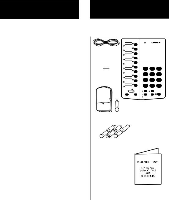
CHAPTER 2 PACKAGE CHECKLIST
Your DIALOGUE RC package includes the items as shown below:
Necklace (for |
|
|
|
|
hanging the |
|
|
|
|
remote control) |
|
|
|
|
|
|
DIALOGUE R C |
|
|
Velcro strip (for |
1 |
2 |
3 |
|
4 |
5 |
6 |
||
remote control |
||||
|
|
|
||
attachment) |
7 |
8 |
9 |
|
|
* |
0 |
# |
Remote Transmitter
and Battery
Batteries (RC-200 only)
Operating Instructions
AC adapter/battery charger
Figure 1 – DIALOGUE RC Components.
2

CHAPTER 3
FEATURES IDENTIFICATION
AIR SWITCH |
AC |
PHONE |
OFF LO HI |
ADAPTER |
LINE |
RINGER |
M1 |
POWER |
TM |
|
M2
|
M3 |
|
|
|
|
|
|
|
M4 |
|
|
|
|
|
|
|
M5 |
|
|
|
|
|
|
|
|
|
|
DIAL OGU E R C |
|
|
|
|
M6 |
1 |
2 |
|
3 |
|
|
|
M7 |
A |
D |
||||
|
|
|
|
|
B |
|
E |
|
|
|
|
|
C |
|
F |
|
|
4I |
5L |
6O |
|||
|
|
|
G |
|
J |
|
M |
|
M8 |
|
H |
|
K |
|
N |
|
M9 |
7 |
P |
8 |
T |
9 |
W |
|
|
R |
U |
X |
|||
|
|
|
S |
|
V |
|
Y |
|
M10 |
* |
0R |
# |
|||
|
|
||||||
|
|
|
|
|
O |
|
|
|
|
|
|
|
P |
|
|
|
VOL |
MUTE |
FLASH/PAUSE |
|
|
||
PROG |
SCAN |
HEADSET |
REDIAL |
ON/OFF |
|||
|
|
||||||
|
|
MIC |
|
|
|
|
|
Jack for Air Switch or accessory switch
AC adapter plug
Phone line jack
Ringer volume control
Lapel Microphone jack
Headset port (Operational in RC–200 only)
Memory location indicators
Memory directory
Memory buttons
Power indicator
Speaker
Battery compartment (underneath)
Tone/pulse selector (underneath)
Remote Flash on/off switch, underneath (Operational in RC–200 only,)
Headset on/off button (Operational in RC–200 only)
Mute button
Flash/Pause button
On/Off button
Redial button
Voice Mail/Unanswered Call
Indicator
Microphone
Scan button
Volume control
Memory Program button
Figure 2 – Features Identification
3
CHAPTER 4
INSTALLATION
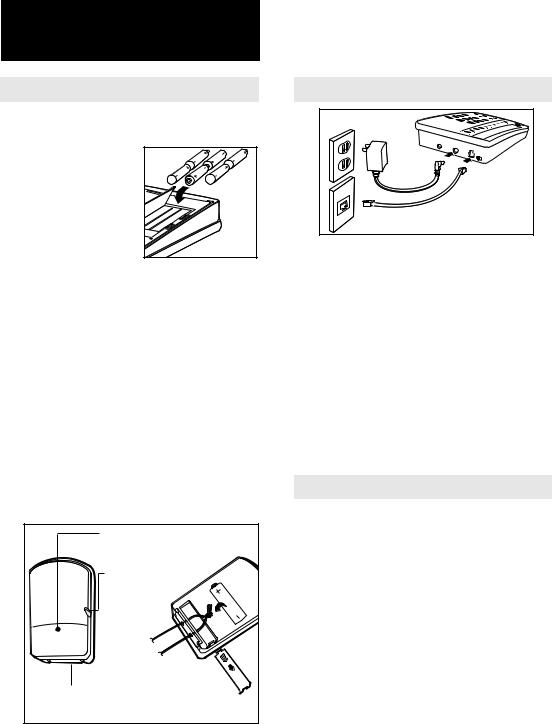
A. Battery (included with RC–200)
Speakerphone
1. Six "AA" size, Nickel Cadmium (NiCad) recharge-
able batteries are  used for back–up
  during a power out-
age (Fig 3). They power the DIALOGUE RC for approximately
3 hours. DO NOT USE ALKALINE BATTERIES, they will damage your equipment.
Remote Transmitter
2.Install the "23A" size 12V alkaline cigarette lighter battery in the Remote Transmitter (included) as shown (Fig 4). With normal usage, it lasts 6–12 months. If the power indicator light is faint or does not come on when the button is pressed, replace the battery. The Remote Transmitter has an operating range of up to 40 feet.
|
Power |
|
|
indicator |
|
|
Jack for |
|
|
accessory |
|
|
switch |
BA |
|
BTTEY |
|
|
|
RY |
|
Thread both |
|
Battery |
ends of necklace |
|
through hole and |
|
|
compartment |
tie a small knot. |
|
(optional)
Figure 4 – Remote Transmitter
B. Connections
Figure 5 – Connection of phone line and AC adapter
1.Connect the phone line and AC adapter as shown.
2.Set the tone/pulse selector (T/P) to T if you have touch tone service, set to P if you have pulse dialing (rotary). (See Fig 2)
The DIALOGUE RC can be placed on a desk, or mounted on the wall. Do not put the DIALOGUE RC on or next to metal surfaces, computers, televisions, radios, microwaves, or other electrical equipment that can cause interference to the wireless signal from the Remote Transmitter.
C. Setting up your RC
The DIALOGUE RC comes with the following operating settings from the factory:
1.Scan rate is 5 seconds per memory location.
2.Voice activated answering (RC–200 only) is off.
3.Unanswered call indicator is on.
4.Voice mail indicator (RC–200 only) is off.
5.Tone/pulse switch set to Tone.
6.Ring volume set to Hi.
7."0" (operator) is programmed into first memory location of M1.
8.Remote flash switch (RC–200 only) is off.
4
 Loading...