


®
©AMERIPHONE products are manufactured by Walker, a Division of Plantronics, Inc. 12082 Western Avenue, Garden Grove, CA 92841
(800) 874-3005 VOICE • (800) 772-2889 TTY/TDD • (714) 897-4703 FAX email: ameriphonecs@plantronics.com website: www.ameriphone.com
©2003 Plantronics, Inc. All rights reserved. Ameriphone, Amplifying Your Life, Plantronics and Walker are all trademarks or registered trademarks of Plantronics, Inc.
|
E |
|
® |
|
N |
XL |
G |
L |
|
P |
I
S
H
The Extra Loud & Clear
XL-40 AMPLIFIED TELEPHONE
with lighted keypad!
E
S
A
Ñ
O
L
Operating Instructions
F
R
A N
Ç
A
I
S
M46802 |
©2003 XL-40 5270-4023 ∆C 10/03 |

Important Safety
IMPORTANT INSTRUCTIONS
Instructions
When using your telephone equipment, basic safety precautions should always be followed to reduce the risk of fire, electric shock and persons including the following:
1.Read and understand all instructions.
2.Follow all warnings and instructions marked on the telephone.
3.Do not use this telephone near a bathtub, wash basin, kitchen sink or laundry tub, in a wet basement, near a swimming pool or anywhere else there is water.
4.Avoid using a telephone (other than a cordless type) during a storm. There may be a remote risk of electrical shock from lightning.
5.Do not use the telephone to report a gas leak in the vicinity of the leak.
6.Unplug this telephone from the wall outlets before cleaning. Do not use liquid cleaners or aerosol cleaners on the telephone. Use a damp cloth for cleaning.
7.Place this telephone on a stable surface. Serious damage and/or injury may result if the telephone falls.
8.Do not cover the slots and openings on this telephone. This telephone should never be placed near or over a radiator or heat register. This telephone should not be placed in a built-in installation unless proper ventilation is provided.
9.Operate this telephone using the electrical voltage as stated on the base unit or the owner’s manual. If you are not sure of the voltage in your home, consult your dealer or local power company.
10.Do not place anything on the power cord. Install the telephone where no one will step or trip on the cord.
11.Do not overload wall outlets or extension cords as this
can increase the risk of fire or electrical shock.
12.Never push any objects through the slots in the telephone. They can touch dangerous voltage points or short out parts that could result in a risk of fire or electrical shock. Never spill liquid of any kind on the telephone.
13.To reduce the risk of electrical shock, do not take this phone

Important Safety
Instructions
apart. Opening or removing covers may expose you to dangerous voltages or other risks. Incorrect reassembly can cause electric shock when the appliance is subsequently used.
14.Unplug this product from the wall outlets and refer servicing to the manufacturer under the following conditions:
A.When the power supply cord or plug is frayed or damaged.
B.If liquid has been spilled into the product.
C.If the telephone has been exposed to rain or water.
D.If the telephone does not operate normally by following the operating instructions. Adjust only those controls that are covered by the operating instructions. Improper adjustment may require extensive work by a qualified technician to restore the telephone to normal operation.
E.If the telephone has been dropped or the case has been damaged.
F.If the telephone exhibits a distinct change in performance.
15.Never install telephone wiring during a lightning storm.
16.Never install telephone jacks in wet locations unless the jack is specifically designed for wet locations.
17.Never touch uninsulated telephone wires or terminals unless the telephone line has been disconnected at the network interface.
18.Use caution when installing or modifying telephone lines.
19.Use only the power cord and batteries indicated in this manual. Do not dispose of batteries in a fire. They may explode. Check with local codes for possible special disposal instructions.
ADDITIONAL SAFETY NOTES FOR CANADIAN USERS
The following items are included as part of the CS-03 Requirements. The standard connecting arrangement for the equipment is CA11A. This product meets the applicable Industry Canada technical specifications.
NOTICE: The Canadian
Department of Communications
E
N G L I S H

Important Safety
Instructions
label identifies certified equipment. This certification means that the equipment meets certain telecommunications network protective operational and safety requirements. The Department does not guarantee that the equipment will operate to the user’s satisfaction. Before installing this equipment, users should ensure that it is permissible to be connected to the facilities of the local telecommunications company. The equipment must also be installed using an acceptable method of connection. In some cases, the company’s inside wiring associated with a single line individual service may be extended by means of a certified connector assembly (telephone extension cord). The customer should be aware that compliance with the above conditions may not prevent degradation of service in some situations. Repairs to certified equipment should be made by an authorized Canadian maintenance facility designated by the supplier. Any repairs or alterations made by the user to this equipment, or equipment malfunctions, may give the telecommunications company
cause to request the user disconnect the equipment.
Users should ensure for their own protection that the electrical ground connections of the power utility, telephone lines and internal metallic water pipe system, if present, are connected together. This precaution may be particularly important in rural areas.
CAUTION: Users should not attempt to make such connections themselves, but should contact the appropriate electric inspection authority, or electrician, as appropriate. The Ringer Equivalent Number is an indication of the maximum number of terminals allowed to be connected to a telephone interface. The termination on an interface may consist of any combination of devices subject only to the requirement that the sum of the Ringer Equivalent Number of all the devices not exceed five.
SAVE THESE INSTRUCTIONS

Contents
Introducing the XL-40 |
|
Warranty Service .............................................................................. |
1 |
Sales Receipt .................................................................................... |
1 |
Help from Ameriphone ...................................................................... |
1 |
Package Checklist ............................................................................ |
2 |
Features .......................................................................................... |
3 |
Setting up Your XL-40 |
|
Installing the Backup Batteries ............................................................ |
4 |
Setting the Dialing Mode .................................................................. |
5 |
Connecting for Desk or Wall Mount .................................................. |
5 |
Desktop Use .............................................................................. |
5 |
For Wall Mounting ...................................................................... |
5 |
Using Your XL-40 |
|
Incoming Voice Volume ...................................................................... |
7 |
Incoming Voice Tone.......................................................................... |
8 |
Ringer Volume and Tone .................................................................... |
8 |
Hold ................................................................................................ |
8 |
Last Number Redial .......................................................................... |
9 |
Flash................................................................................................ |
9 |
Special Features |
|
Unanswered Call/Voice Mail Message Light ...................................... |
10 |
Programming the Memory Buttons...................................................... |
11 |
Direct Audio Output ........................................................................ |
12 |
Cochlear Implant Adapter Cord ........................................................ |
12 |
Connecting to Speech Processor ........................................................ |
12 |
Regulatory Compliance .................................................................... |
13 |
Warranty ........................................................................................ |
19 |
Specifications .................................................................................. |
21 |
Troubleshooting Chart ...................................................................... |
21 |
Index .............................................................................................. |
22 |
E
N G L I S H

Introducing the XL-40
Thank you for selecting the XL-40 Amplified Telephone from Ameriphone. These Operating Instructions and the associated Quick Operating Guide provide you with the information you need to use your XL-40 effectively, easily and safely. Read this manual thoroughly before using your telephone. Keep the manual near the telephone for easy reference.
Warranty Service
Your telephone is designed to provide years of quality service. But, should the phone malfunction and the Trouble-shooting Chart on page 12 not resolve the problem, follow the Warranty procedure on page 19.
Sales Receipt
Be sure to save your sales receipt as proof of purchase date should you need warranty service.
Help from Ameriphone
For help with using your XL-40, call our Customer Relations department at 800-874-3005.
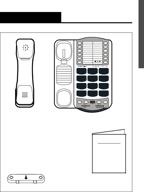
Please make sure your XL-40 package includes the items shown in Figure 1.
1
Package Checklist
M1 |
|
M7 |
M2 |
|
M8 |
M3 |
|
M9 |
M4 |
|
M10 |
M5 |
|
M11 |
M6 |
|
|
¤ |
|
|
1 |
A |
D |
2CB |
3EF |
|
G |
J |
M |
4HI |
5 L |
6 ON |
|
K |
|
P |
T |
W |
7RS |
8UV |
9XY |
HOLD*PROG |
0 |
# |
|
FLASH REDIAL |
|
TONE |
AMPLIFY |
VOL |
|
||
LO |
HI |
|
Handset
Base Unit
Telephone Line Cords |
XL-40 |
|
|
|
OPERATING |
|
|
INSTRUCTIONS |
Handset |
|
AND |
Coil Cord |
|
QUICK GUIDE |
|
|
Operating Guides |
Mounting Bracket |
AC Adapter |
|
|
|
|
Figure 1 - Package Components |
|
2 |
E
N G L I S H
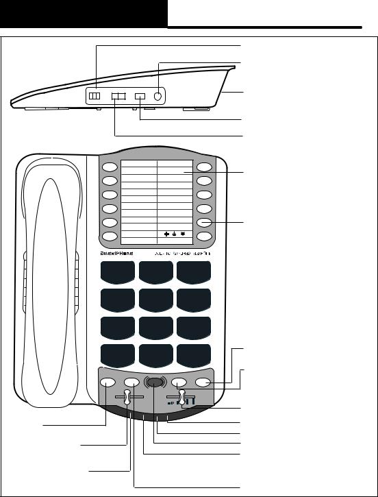
Features on the XL-40
|
|
|
|
|
RINGER volume switch |
|
|
|
|
|
AUDIO OUTPUT jack |
RINGER |
RING TONE |
DIAL |
AUDIO |
|
AC adapter and phone |
Lo Med Hi |
Lo Hi |
T P |
OUTPUT |
|
line connection |
|
|
|
|
|
TONE/PULSE switch |
|
|
|
|
|
RING TONE switch |
|
M1 |
|
|
M7 |
Phone number |
|
|
|
|
|
|
|
M2 |
|
|
M8 |
directory |
|
|
|
|
|
|
|
M3 |
|
|
M9 |
|
|
M4 |
|
|
M10 |
MEMORY button |
|
M5 |
|
|
M11 |
|
|
|
|
|
||
|
M6 |
|
|
|
|
|
|
¤ |
|
|
|
|
1 |
|
A |
D |
|
|
|
2CB |
3EF |
|
|
|
4HI |
|
5KL |
6 ON |
|
|
G |
|
J |
M |
|
|
P |
|
T |
W |
|
|
7RS |
|
8UV |
9XY |
|
|
HOLD*PROG |
0 |
|
# |
REDIAL button |
|
|
FLASH button |
|||
|
|
FLASH |
REDIAL |
||
|
|
|
|||
|
|
AMPLIFY |
|
|
|
|
TONE |
|
|
VOL |
VOL volume slider |
|
LO |
HI |
|
|
|
|
HOLD |
|
|
|
LOW BATTERY indicator |
|
button |
|
|
|
RING flasher |
|
TONE |
|
|
|
AMPLIFY button |
|
slider |
|
|
|
AMPLIFY/MISSED CALLS/ |
|
HOLD |
|
|
|
VOICE MAIL/EXTENSION |
|
|
|
|
IN USE indicator |
|
|
indicator |
|
|
|
|
|
|
|
|
PROG program button |
|
|
|
|
|
|
|
3 |
Figure 2 - Base Unit Controls |
|
|
|
|
|
|
|
|
|
Setting up Your XL-40
There are five initial steps involved in setting up your XL-40 for the first time.
1.Insert four AA alkaline batteries for back-up in case of AC power outage.
2.Decide if you want the phone to sit on a desk or hang on the wall.
3.Connect the telephone components.
4.Program up to 12 telephone numbers to call with the press of a memory button.
5.Set up special features
Installing the Backup Batteries
To install new batteries:
1.Slide open the battery compartment cover on the bottom of the telephone (Figure 3).
2.Install four fresh batteries. Be sure to observe battery polarity as imprinted on the base of the compartment. The battery indicator on the top panel will light up if the batteries are running low.
The phone operates as a regular phone if there is no power or battery.
If there is a power outage, the XL-40 will operate for up to 48 hours with four AA alkaline backup batteries (not included). If the phone is not in use, the batteries may last for several months.
Insert 4 AA batteries 

 here
here
Press in  here with a
tip of a pen 

 to open
Figure 3 - Accessing the Batteries
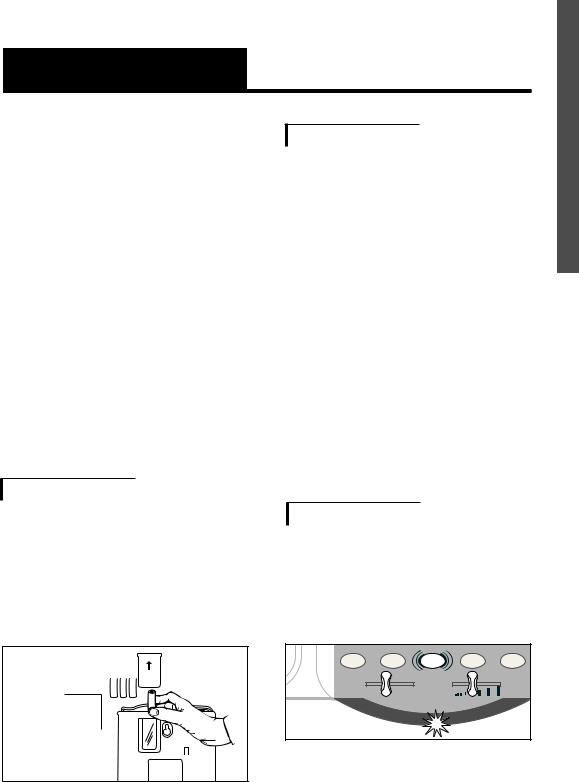
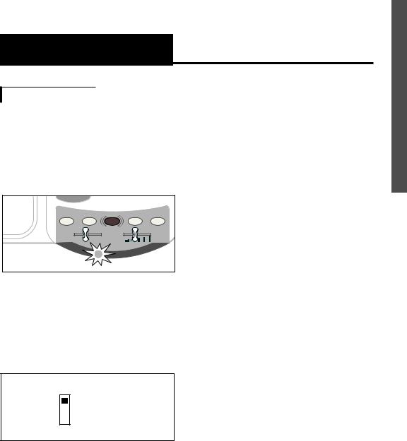
XL-40 Low Battery Indicator Light
If the batteries are weak or not installed, the Low Battery indicator will light up. Install fresh batteries according to the directions above.
HOLD PROG FLASH REDIAL
TONE |
AMPLIFY |
VOL |
|
LO |
HI |
Figure 4 - Low Battery Indicator Light
4
E
N G L I S H
Setting up Your XL-40 (continued)
Setting the Dialing Mode
Set the dial mode switch to T (tone) if you have touch tone service. Set the switch to P (pulse) if you have rotary dialing.
Connecting for Desk or Wall Mount
For Desktop Use
1.Connect one end of the telephone line cord to the “Line” jack on the back of the XL-40 and the other end to the phone outlet on your wall. Connect the handset cord to the telephone as shown in Figure 5.
Line Cord
Handset (Curly) Cord
AC Adapter
Figure 5 - Connecting the Components
2.Plug the AC adapter into an electric outlet and into the AC jack on the telephone as shown in Figure 5.
3.Lift the handset and listen for a dial tone.
The phone is ready to use.
For Wall Mounting
1.Slide the handset hook out of the base as shown in Figure 6 and reverse its position so that the hook points up and will hold the handset when you hang up.
Figure 6 - Reversing the Hook
2.Insert the tabs of the phone base into the slots in the lower position of the base as shown in Figure 7. Push the mounting bracket in and down firmly until it snaps into place.
5
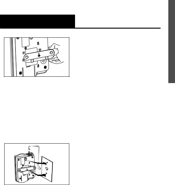
Setting up Your XL-40 (continued)
Figure 7 - Mounting Bracket
for Wall Mounting
3.Locate a desired wall phone jack near an AC outlet and hold phone upright.
4.Plug the short phone line cord into the wall outlet as shown in Figure 8.
- Short phone line cord
Figure 8 - Wall mounting installation
5.Angle the phone downward to feel for the LOWER protruding nail head. Insert the WALL JACK'S nail head into the LOWER part of the phone's mounting bracket.
6.Once the lower nail head has been inserted, insert the UPPER nail head into the phone's bracket and slide the phone down until it is firmly in place on the wall.
7.Once firmly in place, attach the short line cord to the phone, the AC adapter to the phone and attach the phone's handset.
8.Plug the AC adapter into the AC wall outlet. Lift the handset and listen for a dial tone. The phone is now ready to use.
E
N G L I S H
6
Using Your XL-40
Incoming Voice Volume
You can adjust the volume of incoming calls by simply sliding the VOL control. This gives you up to 18 dB more volume. If you want more amplification, follow the directions below.
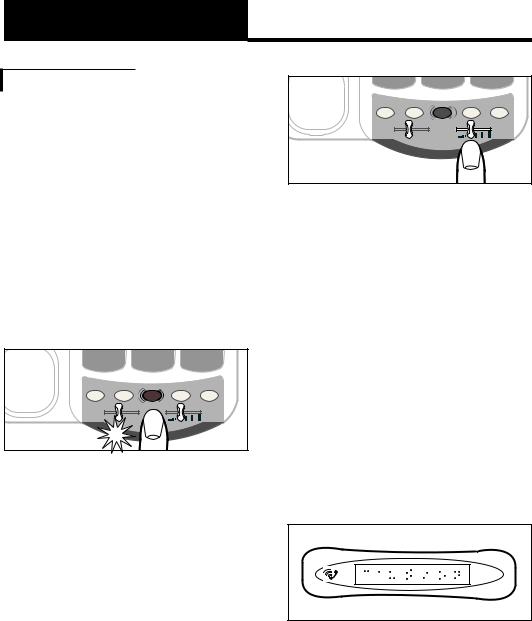
1. Press the AMPLIFY button as shown in Figure 9 to turn the incoming voice amplifier on or off. When AMPLIFY is on, the AMPLIFY indicator comes on.
HOLD*PROG |
0 |
|
# |
FLASH |
REDIAL |
||
TONE |
AMPLIFY |
|
VOL |
|
|
Figure 9 - AMPLIFY Button
and Indicator
2.Adjust the ear piece volume while on a call by moving the VOL slide control in Figure 10. With AMPLIFY on, incoming volume will be up to 40dB louder.
HOLD*PROG |
FLASH |
REDIAL |
TONE |
AMPLIFY |
VOL |
|
||
LO |
HI |
|
Figure 10 - Volume Slide Control
Caution: Repeated incremental exposure to amplification levels greater than 18 dB may be harmful to individuals without hearing disabilities. Therefore, do not remove the warning label attached to the back of the handset. If it is likely that a visually impaired person will use the telephone, securely attach the provided warning printed in Braille to the back of the handset (See Diagram A).
C A U T I O N
U S E W I T H
VOLUME
LOUD
Diagram A.
7
Using Your XL-40 |
|
|
|
E |
(Continued) |
|
|
|
N |
|
|
|
|
G |
Note: In standard use, the amplifier |
0 |
|
# |
L |
|
I |
|||
turns off when you hang up the |
HOLD*PROG |
|
|
|
FLASH |
REDIAL |
S |
||
telephone. This is a useful feature |
TONE |
|
VOL |
|
|
AMPLIFY |
|
|
H |
if many people use the phone. If |
|
|
|
|
|
|
|
|
|
you want the amplifier to always |
|
|
|
|
remain on, slide the Volume Reset |
Figure 12 - Tone Slide Control |
|
||
Override switch on the bottom of |
|
|||
|
|
|
|
|
the phone to ON, as shown in |
Ringer Volume and Tone |
|
|
|
Figure 11. |
|
|
|
|
|
|
|
|
|
MANUAL- OFF
AUTO
- ON
Volume
Reset
Override
Figure 11 - Volume Reset Override
On/Off
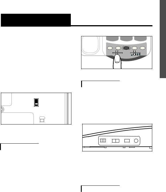
Incoming Voice Tone
1.You can adjust the RINGER VOLUME as high as 95+ decibels. The settings available are LO, MED and HI as shown in Figure 13.
RINGER |
RING TONE |
DIAL |
AUDIO |
Lo Med Hi |
Lo Hi |
T P |
OUTPUT |
The XL-40 provides extra amplification in the sound frequency range you need to boost. To identify the range that best suits your needs, follow these steps:
Figure 13 - Ringer Volume & Pitch
2.The RING TONE has two pitch settings: LO and HI.
1.When you hear a voice on the line, press the AMPLIFY button shown in Figure 9.
2.Adjust the TONE slide control in Figure 12 to suit your hearing.
Hold
To put the line on hold, press the HOLD button and return the handset to its cradle. You will notice the HOLD indicator light comes on.
8
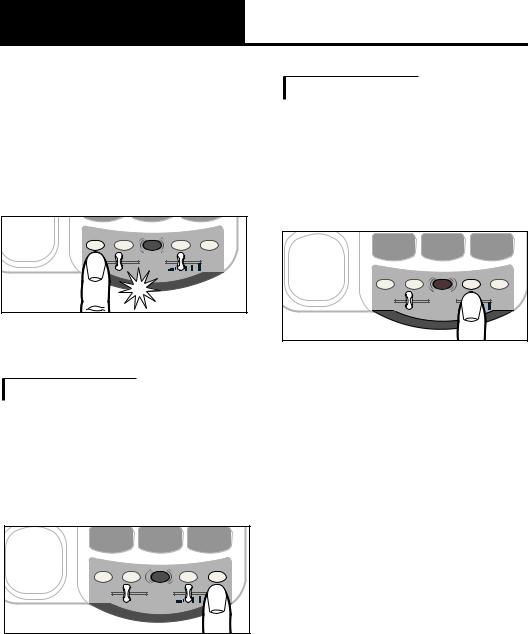
Using Your XL-40 (Continued)
Note: If you pick up an extension phone on the same line when the XL-40 is on HOLD, the XL-40 will release the HOLD, and you can continue your conversation on the extension phone.
|
|
0 |
|
HOLD |
PROG |
FLASH |
REDIAL |
|
|
AMPLIFY |
VOL |
|
|
|
Figure 14 - Hold Button and
Indicator
Last Number Redial
To redial the last number called, lift the handset and press REDIAL. The phone will redial up to 31 digits.
HOLD*PROG |
0 |
|
# |
FLASH |
REDIAL |
||
TONE |
AMPLIFY |
|
|
|
|
|
|
LO |
HI |
|
|
Figure 15 - Redial Button
Flash
Press the FLASH button shown in Figure 16 to access special services available from your local phone company such as Call Waiting and 3-Way Calling.
HOLD*PROG |
0 |
|
# |
FLASH |
REDIAL |
||
TONE |
AMPLIFY |
|
VOL |
|
|
||
LO |
HI |
|
|
Figure 16 - Flash Button
9
Special Features
Unanswered Call/Voice Mail
Message Light
If you subscribe to voice mail messaging with your telephone company, this light flashes if you have a message waiting.
call is not answered by a person or an answering machine after 1 ring, provided that you set the switch underneath the phone to Missed Calls. The light will continue to flash until the handset is lifted or AC power is disconnected.
* 

HOLD |
PROG |
FLASH |
REDIAL |
TONE |
|
AMPLIFY |
VOL |
|
|
||
|
LO |
HI |
|
Figure 17 - Voice Mail Indicator
Note: To turn the Voice Mail feature on or off, adjust the switch underneath the phone.
VMAIL
MISSED CALL
OFF
Figure 18 - Voice Mail Switch
If you do not have voice mail service, the same indicator functions as a missed call indicator. It flashes if an incoming
Note: this feature does not require any optional telephone company services.
It is useful when you are away for a short time while expecting a call. If you don’t want any notification, set the switch on OFF.
E
N G L I S H
10
Special Features (continued)
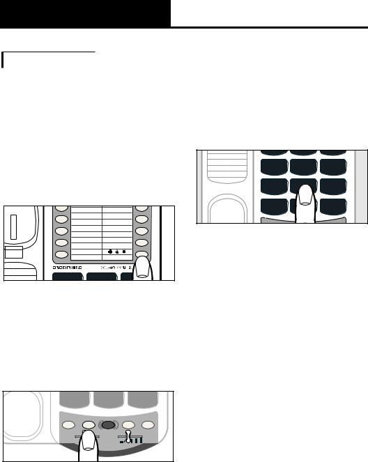
Programming the Memory Buttons
You can automatically dial twelve programmed telephone numbers using the memory buttons shown in Figure 19. Each button can be programmed (or reprogrammed using the same procedure) for a phone number up to 15 digits long.
M3 |
M9 |
M4 |
M10 |
M5 |
M11 |
M6 |
|
|
¤ |
1 |
A |
2B |
|
Figure 19 - Memory Buttons |
|
HOLD*PROG |
0 |
|
# |
FLASH |
REDIAL |
||
TONE |
AMPLIFY |
|
VOL |
|
|
Figure 20 - PROG Button
2.Enter the phone number on the keypad (Figure 21) just as you would dial it normally.
Note: Press REDIAL if you want to insert a brief pause between two numbers.
|
C |
F |
G |
J |
M |
4HI |
5 L |
6 ON |
|
K |
|
P |
|
W |
7RS |
|
9XY |
* |
|
# |
|
|
Figure 21 - Telephone Keypad
3.Press a memory button (Figure
19)to store this number on that button.
4.Immediately hang up the handset.
Note: Any number previously stored at that memory button will be overwritten.
5.To change a stored number, repeat the programming process starting with step 1.
11
Special Features (continued)
Note: Please do not program 911 in any memory button.
Direct Audio Output
The AUDIO OUTPUT socket allows you to connect the XL-40 to a hearing aid, neck loop, cochlear implant or other assistive listening devices.
RINGER |
RING TONE |
DIAL |
AUDIO |
||
o Med Hi |
Lo |
Hi |
T |
P |
OUTPUT |
Figure 22 - Audio Output
Socket
To use this port, plug in a compatible auxiliary cable and connect it to your assistive listening device. Speak into the handset when you use the Audio Output connection.
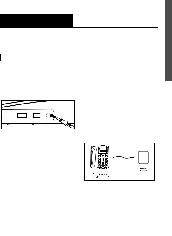
Cochlear Implant Adapter Cord
A cochlear adapter cord is available from Ameriphone that can be used to directly connect the XL-40 to a speech processor.
Connecting the speech processor:
Caution: Before plugging any cord into your speech processor, you must consult your implant manufacturer.
•Plug the mono end of the plug into the speech processor.
•Plug the stereo end of the plug into the Audio Output socket on the phone.
•Speak into the handset when using the Cochlear Implant Adapter Cord
Figure 23 - Connection of
Speech Processor
WARNING! During thunderstorms, avoid using telephones (except cordless models). Electric shock from lightning can occur.
E
N G L I S H
12

Regulatory Compliance
Part 68 of FCC Rules
Information
This equipment complies with Part 68 of the FCC rules and the requirements adopted by the ACTA. On the bottom of this equipment is a label that contains, among other information, a product identifier in the format US:AAAEQ##TXXXX. If requested, this number must be provided to the telephone company.
A plug and jack used to connect this equipment to the premises wiring and telephone network must comply with the applicable FCC Part 68 rules and requirements adopted by the ACTA. A compliant telephone cord and modular plug, RJ11 USOC, is provided with this product. It is designed to be connected to a compatible modular jack that is also compliant. See installation instructions for details.
The REN is used to determine the number of devices that may be connected to a telephone line. Excessive RENs on a telephone
line may result in the devices not ringing in response to an incoming call. In most but not all areas, the sum of RENs should not exceed five (5.0). To be certain of the number of devices that may be connected to a line, as determined by the total RENs, contact the local telephone company. For products approved after July 23, 2001, the REN for this product is part of the product identifier that has the format US:AAAEQ##TXXXX. The digits represented by ## are the REN without a decimal point (e.g., 03 is a REN of 0.3). For earlier products, the REN is separately shown on the label.
If this telephone equipment, the XL-40 telephone, causes harm to the telephone network, the telephone company will notify you in advance that temporary discontinuance of service may be required. But if advance notice isn’t practical, the telephone company will notify the customer as soon as possible. Also, you will be advised of your right to file a complaint with the FCC if you
13

Regulatory Compliance (continued)
believe it is necessary.
The telephone company may make changes in its facilities, equipment, operations or procedures that could affect the operation of the equipment. If this happens the telephone company will provide advance notice in order for you to make necessary modifications to maintain uninterrupted service.
If trouble is experienced with this telephone equipment, for repair or warranty information, please contact Walker / Ameriphone, 1-800- 874-3005. If the equipment is causing harm to the telephone network, the telephone company may request that you disconnect the equipment until the problem is resolved.
DO NOT DISASSEMBLE THIS EQUIPMENT.
This telephone equipment is not intended to be repaired and it contains no repairable parts. Opening the equipment or any attempt to perform repairs will void the warranty. For service or repairs, call 1-800-874-3005.
|
E |
|
|
N |
|
|
G |
|
Connection to party line service is |
L |
|
I |
||
subject to state tariffs. Contact the |
||
S |
||
state public utility commission, |
||
H |
||
public service commission or |
||
|
||
corporation commission for |
|
|
information. |
|
|
If your home has specially wired |
|
|
|
||
alarm equipment connected to the |
|
|
telephone line, ensure the |
|
|
installation of this telephone |
|
|
equipment does not disable your |
|
|
alarm equipment. If you have |
|
|
questions about what will disable |
|
|
alarm equipment, consult your |
|
|
telephone company or a qualified |
|
|
installer. |
|
|
This telephone equipment is |
|
|
hearing aid compatible. |
|
|
We recommend the installation of |
|
|
an AC surge arrester in the AC |
|
|
outlet to which this equipment is |
|
|
connected. The telephone |
|
|
companies report that electrical |
|
|
surges, typically lighting transients, |
|
|
are very destructive to customer |
|
|
terminal equipment connected to |
|
|
AC power sources. |
|
14
Regulatory Compliance (continued)
Customer-Owned Coin/Credit
Card Phones:
To comply with state tariffs, the telephone company must be given notification prior to connection. In some states, the state public utility commission, public service commission or corporation commission must give prior approval of connection.
Part 15 of FCC Rules
Information
This device complies with part 15 of the FCC Rules. Operation is subject to the following two conditions: (1) This device may not cause harmful interference, and (2) this device must accept any interference received, including interference that may cause undesired operation.
Your XL-40 Telephone has been tested and found to comply with the limits of a Class B digital device, pursuant to Part 15 of FCC rules. These limits are
designed to provide reasonable protection against harmful interference in residential installation.
This equipment generates, uses, and can radiate radio frequency energy and, if not installed and used in accordance with the instructions, may cause harmful interference to radio communications. However, there is no guarantee that interference will not occur in a particular installation; if this equipment does cause harmful interference to radio or television reception, which can be determined by turning the equipment off and on, you are encouraged to try to correct the interference by one of the following measures:
1.Where it can be done safely, reorient the receiving television or radio antenna.
2.To the extent possible, relocate the television, radio or other receiver with respect to the telephone equipment.
15

Regulatory Compliance (continued)
(This increases the separation between the telephone equipment and the receiver.)
3.Connect the telephone equipment into an outlet on a circuit difference from that
to which the television, radio, or other receiver is connected.
4.Consult the dealer or an experienced radio/TV technician for help.
CAUTION: Changes or modifications not expressly approved by the manufacturer responsible for compliance could void the user’s authority to operate the equipment.
THE PARTY RESPONSIBLE FOR PRODUCT COMPLIANCE
Ameriphone Products by Walker, A Division of Plantronics, Inc. 12082 Western Avenue
Garden Grove, CA 92841 Telephone: 800-874-3005
Industry Canada Technical
Specifications
This product meets the applicable Industry Canada technical specifications.
Before installing this equipment, users should ensure that it is permissible to be connected to the facilities of the local telecommunications company. The equipment must also be installed using an acceptable method of connection. In some cases, the company’s inside wiring associated with a single line individual service may be extended by means of a certified connector assembly (telephone extension cord). The customer should be aware that compliance with the above conditions may not prevent degradation of service in some situations.
Repairs to certified equipment should be made by an authorized Canadian maintenance facility designated by the supplier. Any repairs or alterations made by the
E
N G L I S H
16

Regulatory Compliance (continued)
user to this equipment, or equipment malfunctions, may give the telecommunications company cause to request the user to disconnect the equipment.
Users should ensure for their own protection that the electrical ground connections of the power utility, telephone lines and internal metallic water pipe system, if present, are connected together. This precaution may be particularly important in rural areas.
Caution: Users should not attempt to make such connections themselves, but should contact the appropriate electric inspection authority, or electrician, as appropriate.
The Ringer Equivalence Number is an indication of the maximum number of terminals allowed to be connected to a telephone interface. The termination on an interface may consist of any combination of devices subject only to the requirement that the sum of the Ringer Equivalence Numbers of all
the devices does not exceed five.
[The term “IC:” before the certification/registration number only signifies that the Industry Canada technical specifications were met.]
17

E
N G L I S H
18

IMPORTANTWarranty INSTRUCTIONS
This warranty applies only to Ameriphone products that are purchased and used in the United States or Canada.
Ameriphone warrants the XL-40 Amplified Telephone against any defect in materials or workmanship for the period of one year from the date of purchase.
If your Ameriphone product is defective and returned within 30 days of the date of purchase, your Ameriphone dealer will replace it at no charge.
If returned after 30 days but within one year from the date of purchase, we will repair or replace it at no charge. In the repair of your XL-40 Amplified Telephone, we may use new or reconditioned replacement parts. If we elect to replace your XL-40 Amplified Telephone, we may replace it with a new or reconditioned product of the same or similar design. Repair or replacement will be warranted for either 90 days or the remaining time on the original
warranty period, whichever is longer.
Implied warranties, including those of fitness for a particular purpose and merchantability (an unwritten warranty that the product is fit for ordinary use), are limited to one year from date of purchase. We will not pay for loss of time, inconvenience, loss of use of your XL-40 Amplified Telephone, or property damage caused by your XL-40 Amplified Telephone or its failure to work, or any other incidental or consequential damages. Some states do not allow limitations on how long an implied warranty lasts or the exclusion of incidental or consequential damages, so the above exclusions or limitations may not apply to you. To get warranty service for your XL-40 Amplified Telephone, you must provide proof of the purchase date. Within 30 days of the date of purchase, return your XL-40 Amplified Telephone to the place where you purchased it for immediate replacement. After 30 days, call
19

IMPORTANT SAFETY Warranty INSTRUCTIONS
Ameriphone at 800-874-3005 voice or 800-772-2889 TTY for the authorized service center nearest you. You must prepay all shipping costs.
We suggest you save the original package materials in the event you need to ship the XL-40 Amplified Telephone. When shipping for warranty repair, include your name, address, phone number, proof of date of purchase, and a description of the problem. After repairing the product, we, (or the service center) will ship it back to you at no cost within the United States and Canada. CANADIAN RESIDENTS: call Ameriphone at 800-874-3005, 800-772-2889 TTY for instructions.
This warranty does not cover defects resulting from accidents, damage while in transit to our service location, alterations, unauthorized repair, failure to follow instructions, misuse, use outside the United States or Canada, fire, flood, and acts of
God. Nor do we warrant the product to be compatible with any particular telephone equipment, party line, key telephone systems or more sophisticated switching systems.
If your XL-40 Amplified Telephone is not covered by this warranty, call us at 800-874-3005 voice or 800-772-2889 TTY for advice as to whether we will repair your XL-40 Amplified Telephone and other repair information. The repair shall be warranted for 90 days.
E
N G L I S H
20

IMPORTANTSpecificationsINSTRUCTIONS
Maximum gain
High frequency (3kHz): 40dB Wide band (300 to 3000Hz): 30dB
Tone control range
Full range: 300 to 3000Hz using one slide control.
Dimensions
Size: 9 1/2" x 7" x 3 1/4"
Weight: 2.52 lbs.
Power Requirements
AC Adapter: 9VDC, 300 mA Batteries: 4 AA alkaline batteries (not included)
21
Troubleshooting Chart
The chart below will help you solve most problems that may arise during operation of your telephone. Should the difficulty continue, contact Ameriphone or your authorized dealer for assistance.
|
CAUSE AND |
|
SYMPTOM |
CORRECTIVE |
|
|
ACTION |
|
No dial tone |
Check all phone |
|
|
cord connections. |
|
No number |
No number stored in |
|
dialed when |
that memory |
|
memory |
button. See: |
|
button pressed |
“Programming the |
|
|
Memory buttons”, P. 10. |
|
Call cannot |
See “Setting Up |
|
be dialed, |
Your Phone” to reset |
|
or dials |
the dial mode |
|
switch, P. 5, 6. |
||
very slowly |
||
|
||
Call comes in |
1. Check that line |
|
cord is not loose. |
||
but phone |
2. Check that AC |
|
does not ring. |
adapter is |
|
|
plugged in. |
|
|
|
|
Phone locks up. |
1. Unplug the |
|
No |
AC adapter. |
|
2. Remove backup |
||
functions |
batteries. |
|
operate |
3.Then, plug in the |
|
|
AC adapter |
|
|
and reinstall |
|
|
batteries. |
|
|
|
 Loading...