


T M
Installation
Instructions
2904
Centerset Lavatory Faucet with
Speed Connect™ Drain
Congratulations on purchasing your American Standard faucet with Speed Connect drain, a feature found only on American Standard faucets.
Speed Connect Drain*
•1/3 of the parts, installs in 1/3 of the time
•No tools needed
•Never needs adjustment
•Guaranteed to seal properly the first time, every time.
Certified to comply with ANSI A112.18.1
M968423 Rev . 1 . 2
*Your new American Standard faucet is designed to work only with the Speed Connect drain. Helpful tips for removing your current drain can be found in the Troubleshooting section of these instructions.
To ensure that your installation proceeds smoothly-please read these instructions carefully before you begin.
Recommended tools
Screwdriver Channel Locks Adjustable Wrench Tubing Cutter
1 |
|
|
Turn off hot and cold water |
|
INSTALL FAUCET |
CAUTION |
|||
|
supplies before beginning. |
Turn off hot and cold water supplies before beginning.
Insert FAUCET (1) and CABLE CONNECTOR (2) through mounting holes of Sink or mounting surface. Fig. A.
Assemble LOCKNUTS (3) onto SHANKS (4) ( from under side of Sink. Hand tighten firmly. Fig. B.
(HAND TIGHTEN)
3
4
Fig. B.
2
Fig. A.
4 |
POP-UP |
CABLE |
SINK OR
MOUNTING
SURFACE
3
2
1

2 INSTALL POP-UP DRAIN
Remove CLEAR PLASTIC COVER (1). Remove CARDBOARD SPACER (2) from under DRAIN POP-UP (3). Fig. A.
Drop DRAIN BODY (4) through sink drain hole. Make sure WHITE FOAM GASKET (5) is under flange of DRAIN BODY (4). Fig. B.
Note: No plumber’s putty or caulk is required.
The CABLE ATTACHMENT POINT (6) must face towards the rear of the SINK. Fig. B.
Fig. A. |
Fig. B. |
|
REAR OF |
|
|
|
SINK |
1 |
|
|
|
3 |
|
|
4 |
|
|
5 |
6 |
|
|
|
|
2 |
|
|
SINK |
|
|
DRAIN |
|
|
|
|
HOLE |
3 INSTALL BLACK GASKET
Install BLACK CONE GASKET (1) onto DRAIN BODY (2) from below.
Note: The flat side of the BLACK CONE GASKET (1) must face down.
2
1
 FLAT SIDE OF GASKET MUST FACE DOWN
4 INSTALL GRAY LOCKNUT
Install GRAY LOCKNUT (1) onto DRAIN BODY (2) from below SINK. Fig. A.
Note: The flat side of the GRAY LOCKNUT (1) must face up.
Tighten firmly by hand. No tools are required. Check DRAIN FLANGE in SINK to ensure that WHITE FOAM GASKET (3) is fully compressed and not visible. Fig. B.
Fig. A. |
Fig. B. |
2 |
|
|
DRAIN |
|
FLANGE |
|
FLAT SIDE OF |
|
GRAY LOCKNUT |
|
MUST FACE UP |
1 |
3 WHITE FOAM |
|
GASKET |
|
NOT VISIBLE |
5 POP-UP KNOB |
DOWN |
|
|
POP-UP KNOB (1) must be fully down. |
1 |
M968423 Rev . 1 . 2
2
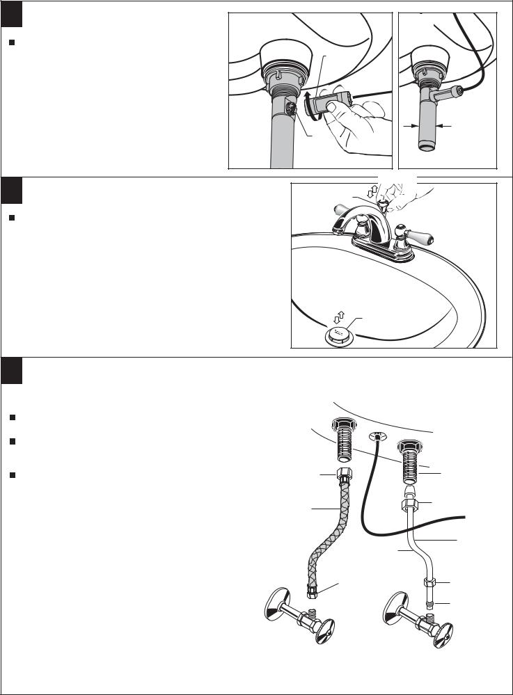
6 ATTACH CABLE CONNECTOR |
Fig. A. |
Fig. B. |
Thread CABLE CONNECTOR (1) clockwise |
|
|
onto DRAIN BODY CONNECTION (2) and |
|
1 |
hand tighten. Fig. A. |
|
|
|
|
|
Your new POP-UP DRAIN installation is |
|
|
now complete. Fig. B. |
|
|
Note: Tailpeice on pop-up drain is 1-1/4” O.D. |
|
|
Fig. B. |
|
|
|
|
1-1/4” O.D. |
|
|
2 |
7 CHECK OPERATION OF POP-UP |
1 |
Operate LIFT KNOB (1) to verify that STOPPER (2) opens and |
|
closes. Fig. B. |
|
Note: If STOPPER (2) does not open and close properly then refer to the “troubleshooting section” of these instructions.
8 MAKE WATER SUPPLY AND WASTE CONNECTIONS
NOTE: FLEXIBLE SUPPLIES OR BULL-NOSE RISERS MUST BE
PURCHASED SEPARATELY.
Connect water supply to FAUCET (1) with 1/2" IPS FLEXIBLE
SUPPLIES (2) or 3/8" O.D. BULL-NOSE RISERS (3).
Use adjustable wrench to tighten connections. Do not over tighten. Be careful not to kink copper supply when bending. Use tubing cutter to cut to proper length.
Connect 1-1/4” O.D. tailpiece on POP-UP DRAIN to waste outlet.
1/2" PIPE |
1 |
THREAD |
|
2 |
COUPLING |
NUT |
|
FLEXIBLE |
|
SUPPLIES |
|
|
3 |
|
3/8 O.D. |
|
BULL-NOSE |
|
RISERS |
3/8” COMPRESSION |
COMPRESSION |
CONNECTION |
NUT |
|
FERRULE |
HOT |
COLD |
M968423 Rev . 1 . 2
3
 Loading...