


INSTALLATION INSTRUCTIONS
Champion®4
Model 2004 Normal Height Elongated One Piece Toilet
Model 2034 Right Height® Elongated One Piece Toilet
Thank you for selecting American Standard - the benchmark of fine quality for over 100 years. To ensure this product is installed properly, please read these instructions carefully before you begin. (Certain installations may require professional help.) Also be sure your installation conforms to local codes.
! CAUTION: PRODUCT IS FRAGILE. TO AVOID BREAKAGE AND POSSIBLE INJURY HANDLE WITH CARE!
NOTE: Pictures may not exactly define contour of china and components.
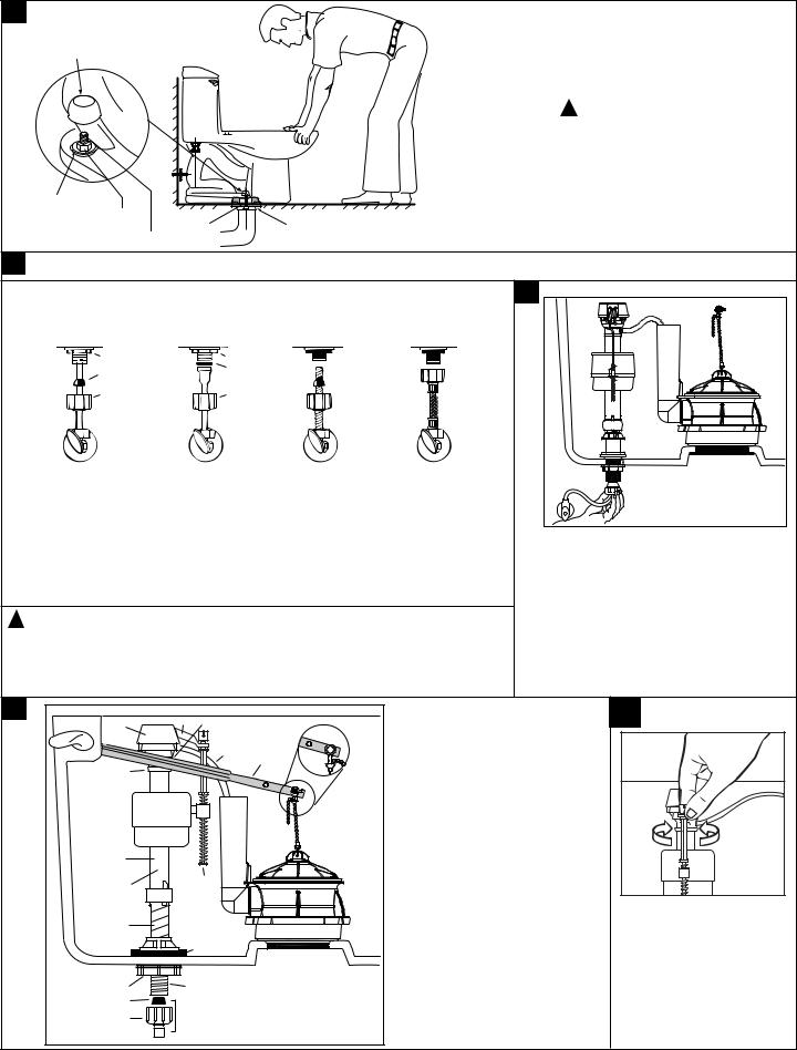
NOTE: BACK-TO-BACK INSTALLATION |
|
|
|
|
|
|
|
|
|
|
|
|
|
|
|
|
|
|
|
|
|
|
|
|
|
|
||
|
|
|
|
|
|
|
|
|
|
|
|
|
|
|
|
|
|
|
|
|
|
|
|
|
|
|||
Depending upon your plumbing and venting conditions, the flow from |
|
|
|
|
|
|
|
|
|
|
|
|
|
|
|
|
|
|
|
|
|
|
|
|
|
|
||
|
|
|
|
|
|
|
|
|
|
|
|
|
|
|
|
|
|
|
|
|
|
|
|
|
|
|||
the Champion in a back-to-back installation may create a vacuum on |
|
|
|
|
|
|
|
|
|
|
|
|
|
|
|
|
|
|
|
|
|
|
|
|
|
|
||
|
|
|
|
|
|
|
|
|
|
|
|
|
|
|
|
|
|
|
|
|
|
|
|
|
|
|||
the system and draw water from the opposing bowl. The National |
|
|
|
|
|
|
|
|
|
|
|
|
|
|
|
|
|
|
|
|
|
|
|
|
|
|
||
|
|
|
|
|
|
|
|
|
|
|
|
|
|
|
|
|
|
|
|
|
|
|
|
|
|
|||
Standards Plumbing Code prohibits the use of a cross fitting for |
|
|
|
|
|
|
|
|
|
|
|
|
|
|
|
|
|
|
|
|
|
|
|
|
|
|
||
|
|
|
|
|
|
|
|
|
|
|
|
|
|
|
|
|
|
|
|
|
|
|
|
|
|
|||
drainage as throw over is possible. The code does approve a |
|
|
|
|
|
|
|
|
|
|
|
|
|
|
|
|
|
|
|
|
|
|
|
|
|
|
||
|
|
|
|
|
|
|
|
|
|
|
|
|
|
|
|
|
|
|
|
|
|
|
|
|
|
|||
directional "Y" style fitting with proper venting to direct the water |
|
|
|
|
|
|
|
|
|
|
|
|
|
|
|
|
|
|
|
|
|
|
|
|
|
|
||
Recommended fitting type for back-to-back installations. |
||||||||||||||||||||||||||||
downward and away from the other toilet. |
||||||||||||||||||||||||||||
|
|
|
|
|
|
|
|
|
|
|
|
|
|
|
|
|
|
|
|
|
|
|
|
|
|
|
||
RECOMMENDED TOOLS AND MATERIALS |
|
|
|
|
|
|
|
|
|
|
|
|
|
|
|
|
|
|
|
|
|
|
|
|
|
|
||
Regular Screwdriver |
Adjustable Wrench |
Putty Knife |
|
Sealant |
Carpenters Level |
|||||||||||||||||||||||
Wax Ring/Gasket |
Flexible Supply Tube |
Closet Bolts |
|
Hacksaw |
Tape Measure |
|||||||||||||||||||||||
1REMOVE OLD TOILET
a.Close toilet supply valve and flush tank completely. Towel or sponge remaining water from tank and bowl.
b.Disconnect and remove supply line. NOTE: If replacing valve, first shut off main water supply!
c.Remove old mounting hardware, remove toilet and plug floor waste opening to prevent escaping sewer gases.
d.Remove closet bolts from flange and clean away old wax, putty, etc. from base area. NOTE: Mounting surface must be clean and level before new toilet is installed!
2ROUGHING-IN DIMENSIONS:
NOTE: Distance from wall to closet flange centerline must be as listed below:
FINISHED WALL |
|
Model 2004 |
FINISHED WALL |
|
|
|
||
|
29-3/4 |
|
|
29-3/4 |
|
Model 2034 |
||
|
(756mm) |
|
|
(756mm) |
|
|||
1-3/4 (44mm) |
|
|
1-3/4 (44mm) |
|
|
|
||
8 |
C/L OF SEAT |
|
16-3/4 |
8 |
C/L OF SEAT |
|
16-3/4 |
|
(203mm) |
POST HOLES |
|
(425mm) |
(203mm) |
POST HOLES |
|
(425mm) |
|
5-1/2 (140mm) |
|
5-1/2 (140mm) |
|
|
||||
|
CENTERS |
|
|
|
CENTERS |
|
|
|
|
18-1/2 |
|
|
|
18-1/2 |
|
|
|
|
(470mm) |
|
|
|
(470mm) |
|
|
|
1 |
|
|
|
1 |
|
|
|
|
(25mm) |
|
|
|
(25mm) |
|
|
|
|
|
|
SUPPLY |
17-3/4 |
|
|
SUPPLY |
17-3/4 |
|
|
|
(451mm) |
|
|
(451mm) |
29-1/2 |
||
|
|
AS |
28-1/8 |
|
|
AS |
|
|
|
|
REQ'D |
(714mm) |
|
|
REQ'D |
|
(749mm) |
|
|
15 |
|
|
|
16-1/2 |
|
|
4 |
|
(381mm) |
7 |
3-3/4 |
|
(419mm) |
7 |
|
|
|
|
|
|
||||
(102mm) |
|
|
(95mm) |
|
|
|
||
|
|
(178mm) |
|
|
(178mm) |
|
||
|
|
|
|
|
|
|
||
1-1/4 |
1/2 |
*4-1/2 |
|
1-1/4 |
1/2 |
*4-1/2 |
|
FINISHED |
(32mm) |
(13mm) |
FINISHED |
(32mm) |
(13mm) |
|
|||
10-3/4 |
13-1/2 |
(114mm) |
FLOOR |
10-3/4 |
13-1/2 |
(114mm) |
|
FLOOR |
|
|
|
||||||
(273mm) |
(343mm) |
|
10-3/4 |
(273mm) |
(343mm) |
|
10-3/4 |
|
12 |
C/L OF OUTLET |
(273mm) |
12 |
C/L OF OUTLET |
(273mm) |
|
||
(305mm) |
|
(305mm) |
|
|
||||
|
|
|
|
|
|
|
|
|
3
CLOSET
FLANGE
A
CLOSET
BOLTS
INSTALL CLOSET BOLTS
Install closet bolts in flange channel, turn 90°, and slide into place 6" (152mm) apart and parallel to wall.
4 |
5 |
SEALANT |
WAX RING |
|
INSTALL WAX SEAL
Invert toilet on floor (cushion to prevent damage), and install wax ring evenly around waste flange (horn), with tapered end of ring facing toilet. Apply a thin bead of sealant around toilet base.
NUT
TAPERED
WASHER
CLOSET |
FLANGE |
|
BOLT |
||
|
POSITION TOILET ON FLANGE
a.Unplug floor waste opening and install toilet on closet flange so bolts project through mounting holes.
b.Loosely install retainer washers and nuts. Side of washers marked "THIS SIDE UP" must face up!
P r o d u c t n a m e s l i s t e d h e r e i n a r e t r a d e m a r k s o f A S A m e r i c a , I n c . |
730865-100 Rev. M |
© A S A m e r i c a , I n c . 2 011 |
|
S A V E F O R F U T U R E U S E
6
|
INSTALL TOILET |
BOLT CAP |
a. Position toilet squarely to wall and, with a rocking motion, |
|
|
|
press bowl down fully on wax ring and flange. Alternately |
|
tighten nuts until toilet is firmly seated on floor. |
|
! CAUTION: |
|
DO NOT OVERTIGHTEN NUTS |
|
OR BASE MAY BE DAMAGED! |
|
b. Install caps on washers. (If necessary, cut bolt height to |
|
size before installing caps.) |
|
c. Smooth off the bead of sealant around base. Remove |
WASHER |
excess sealant. |
NUT |
|
BOLTS |
CLOSET FLANGE |
CLOSET BOLT |
|
7 INSTALL TOILET SEAT Install toilet seat in accordance with manufacturer's directions.
8a |
Before continuing, determine the type of water supply connection you have from |
|
the chart below and use the appropriate assembly parts required to properly |
|
reconnect the water supply. DO NOT use plumber's putty to seal these fittings.
METAL/COPPER |
METAL FLANGED |
|
FLARED TUBING |
TUBING |
|
LOCK NUT |
LOCK NUT |
|
CONE |
EXISTING |
|
WASHER |
||
WASHER |
||
|
||
COUPLING |
EXISTING |
|
COUPLING |
||
NUT |
||
NUT |
||
|
||
WATER |
WATER |
|
SHUT-OFF |
SHUT-OFF |
These parts must be used as illustrated |
Use existing |
|
coupling nut |
||
to insure water-tight connection. Use of |
||
and washer. |
||
existing coupling nut may result in water |
||
|
||
leakage. Water supply tube or pipe |
|
|
must extend at least 1/2" inside |
|
|
threaded shank of valve (does not apply |
|
|
to flanged tubing). |
|
METAL SPIRAL
TUBING


 LOCK NUT
EXISTING

 CONE WASHER
 COUPLING
NUT
WATER
SHUT-OFF
Use existing spiral cone washer. Fluidmaster cone washer may not seal completely on spiral type supply line.
VINYL/BRAIDED
CONNECTOR


 LOCK NUT
 COUPLING
NUT
WATER
SHUT-OFF
Captive cone washers already included. No additional washers needed.
|
|
CAUTION: Overtightening of |
CAUTION: DO NOT USE |
|
|
|
LOCK NUT or COUPLING |
|
CONE WASHER WITH |
|
|
|
NUT could result in breakage |
|
PLASTIC SUPPLY LINE. |
|
and potential flooding. |
!WARNING: Do not use plumber’s putty, pipe dope, or any other sealant on the water supply connection to this tank. If the connection leaks after hand tightening, replace the supply line. If the connection continues to leak with the new supply line, replace the fill valve. Warranty is void if any type of sealant is used on the water supply connection.
8b |
With correct washers in place (see Step 8a), tighten COUPLING NUT 1/4 turn beyond hand tight.
DO NOT OVERTIGHTEN.
9
TOP |
ARM |
NIPPLE |
|
|
|
|
|
|
|
REFILL |
|
|
|
TUBE |
TANK |
|
|
|
LEVER |
CRITICAL LEVEL |
|
|
|
MARK ("C.L.") |
|
|
|
MUST BE |
|
|
|
1" ABOVE |
|
|
|
OVERFLOW PIPE |
FLOAT |
|
|
|
|
|
|
|
CUP |
|
Fig. 9a |
|
|
|
|
FILL |
|
|
|
VALVE |
|
|
|
VALVE |
WATER LEVEL |
|
|
ADJUSTMENT |
|
||
BODY |
|
||
ROD |
|
||
|
|
||
ADJUSTABLE |
|
|
HEIGHT |
|
|
|
SHANK |
|
|
WASHER |
|
LOCK NUT |
THREADED |
|
CONE WASHER |
SHANK |
|
PARTS FOR WATER |
||
|
||
COUPLING NUT |
CONNECTION |
|
(SEE STEP 8) |
||
(HAND TIGHT ONLY) |
Diagram 1 |
ADJUSTMENTS: a. Turn supply on.
Adjust water level to level indicated on tank by adjusting float cup. See Step 10.
b.
If bowl fails to siphon, an adjustment may be required with the lift chain. Simply remove the bead chain from the retainment clip (see Fig. 9a) and take up slack on the chain, and reinsert on lift rod. Make sure the chain is not too taut.
10 |
Turn on water supply. Submerge the FLOAT CUP under the water for 30 seconds. Adjust the water to desired level by turning WATER LEVEL ADJUSTMENT ROD and moving FLOAT CUP up or down.
- 2 - |
730865-100 Rev. M |
 Loading...