

Page 1
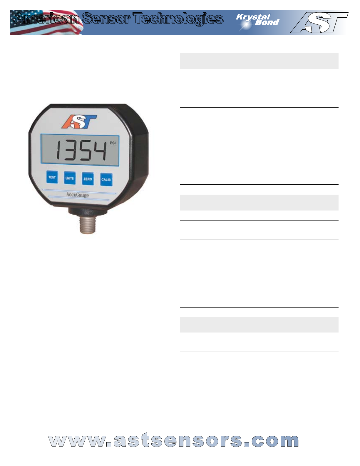
AccuGauge AG200
American Sensor Technologies
American Sensor Technologies
T
A
Your sensor business partner...
TM
Technology
by AST
TM
Bond
K
rystal
Media Isolated 4-20mA Loop-Powered
Digital Pressure Gauge
The AG200 is a media-isolated, digital
pressure gauge that offers a 4-20mA
output signal with a large LCD display.
Utilizing Krystal Bond™ Technology, the
AG200 provides the same quality and
performance as AST’s sensors, with a
local readout. The AG200 also has the
optio n of ze ro and span cali brat ion,
allowing the user to reset the gauge, or
adjust the calibration points to their exact
needs.
American Sensor Technologies
450 Clark Drive
Mount Olive, NJ 07828 USA
Ph 973.448.1901 Fx 973.448.1905
Email: [email protected]
PERFORMANCE @ 25°C (77°F)
Pressure Range
Measurement Units
(Display)
Accuracy
Stability (1 year) ±0.25%FS (typ)
Over Range Protection
Burst Pressure
Pressure Cycles >100 Million
ENVIRONMENTAL DATA
Temperature
Operating
Storage
Thermal Limits
Compensated
Range
TC Zero
TC Span <±1.5% of FS
ELECTRICAL DATA
Loop Current
Update Rate
Display Update
Rate
Power 7.5 to 32VDC
Output 4 – 20mA loop powered
Reverse Polarity
Protection
A number of preset ranges
are available (see page 2)
PSI, BAR, kg/cm, ATM,
InH20, InHg, mAmps
< ± 0.5% BFSL (includes
Non-linearity, Hysteresis
and Non-repeatability)
2X Rated Pressure
5X or 20,000 psi
whichever is less
-10°C to 70°C
(14°F to 158°F)
-40°C to 65°C
(-40°F to 150°F)
0°C to 55°C
(32°F to 130°F)
<±1.5% of FS
(<+/- 3.0% for 0-25 PSI)
32 times per Second
3 times per second
Yes
www.astsensors.com
Page 2
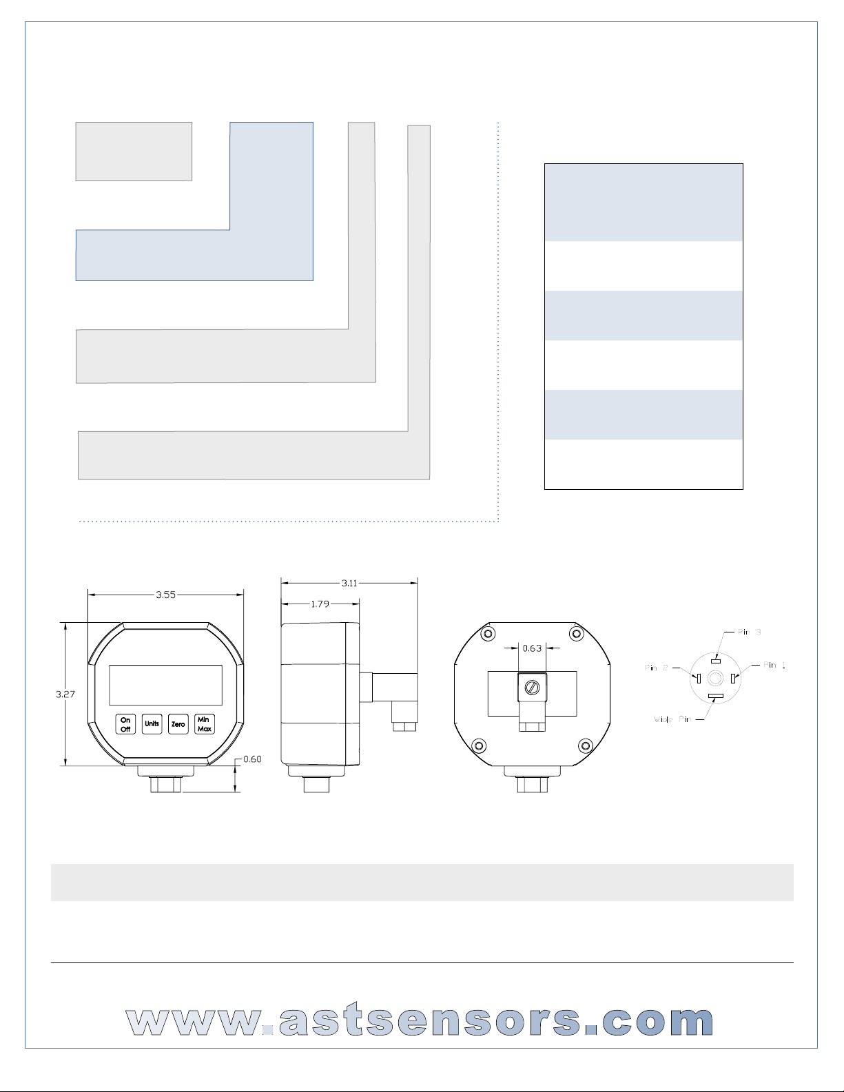
ORDERING INFORMATION
AG200 A 00100 P 4 E 0 000
Series type
A=1/4” NPT male
J= 1/8” NPT female
Pressure range
Insert 5 digit pressure
range code from chart
Pressure unit
P=PSI
Outputs
4=4-20mA (loop powered)
Electrical
E=Mini DIN 43650 (mate included)
Wetted Material
0=17-4
Options
PRESSURE RANGES
Gage
PSIG
Pressure
Range
Code
0-50 00050
0-100 00100
0-250 00250
0-500 00500
0-1000 01000
Pin 2 = 4-20mA output
Pin 3 = +V
WARRANTY
Workmanship - AST, Inc. pressure transmitters have a limited one-year warranty to the original purchaser. AST, Inc. will replace or
repair, free of charge, any defective transmitter. This warranty does not apply to any units that have been modied; misused, neglected
or installed where the application exceeds published ratings. AST’s sensors are made with pride in New Jersey, USA. If in the area
please feel free to stop by for a visit!
Installation/Applications - The purchaser is responsible for media compatibility, functional adequacy, and correct installation of the
transmitter.
www.astsensors.com
© 2007 American Sensor Technologies Inc. All specications are subject to change without notice. Form: dataAG200, Rev 10/9/07
Page 3
American Sensor Technologies
American Sensor Technologies
T
A
Your sensor business partner...
TM
AG200 - OPERATION
Loop Voltage
Select a loop power supply voltage and total loop resistance so that
when the loop current is 20 mA, the gauge will have at least 7.5 VDC at
its terminals. Too large a loop resistance will cause the gauge output to
“limit” or saturate before reaching its full 20 mA output.
The minimum loop supply voltage may be calculated from the formula:
Vmin = 7.5V + (20mA x Total loop resistance).
If the loop voltage drops too low, the AG200 will display the LOW LOOP
icon. When the LOW LOOP icon is displayed, all calibration functions,
described below, are disabled.
Normal Operation
Under normal operation the AG200 displays the pressure in the selected
units and outputs 4mA to 20mA current proportional to the pressure. The
AG200 outputs 4mA for zero or low end pressure, and 20mA for full scale or
high end pressure. If the pressure reading goes outside the specied range,
the AG200 will output as low as 3.5mA or as high as 24mA loop current.
Press the UNITS button the change the displayed units. The AG200
displays PSI, bar, Atm, Kg/cm2, InHg, InH2O and mA loop current. The
UNITS button does not affect the current output.
Generating a Test Current
When the TEST button is held depressed, the display and loop current are
switched to a test level. This test mode will allow setup and testing of the
current loop by switching to this test level whenever desired without having
to alter the system pressure. To change the test output level, press the
CALIB button, while the TEST button is depressed. Each time the CALIB
button is pressed, the test level current increases by 2mA.
Zero Pressure Calibration
The gauge port must be open with no pressure or vacuum applied. Press
the ZERO and CALIB buttons together for about 3 seconds to zero the
unit. The buttons can be released when the gauge shows a zero pressure
reading. Note: It is best to perform this step when pressure units (not mA)
are shown on the display. The zero calibration is retained after the unit
is turned off.
Span Pressure Calibration
Span calibration should only be attempted if the user has access to
a pressure reference of known accuracy. The calibration equipment
should be at least four times the gauge accuracy. Zero calibration must
be done before span calibration. To perform span perform the following
steps:
1. Choose the calibration units by using the UNITS button.
2. Hold the CALIB button for about 3 seconds.
3. The display will alternate between CAL and the required calibration
pressure. For instance, if the unit needs to be calibrated at 500 PSI, the
display will show:
CAL then 500
4. Connect the unit to a pressure source and apply the pressure indicated
on the display.
5. Press and hold the CALIB button for about 3 seconds to complete the
calibration. If the calibration is successful, the display will show:
Done
If there is an error, the display will show:
Err
An error condition will occur if the user tries to calibrate the unit beyond +/10% of the factory calibration.
• To cancel the calibration at any point during the procedure, press and release the CALIB button.
• Factory calibration can be restored by entering the calibration state, as
described in step 2, then holding the ZERO button for about 3 seconds. The
unit will display:
FAC
to indicate that factory calibration has been restored.
Current Output Calibration
The AG200 has been set at the factory to be in agreement between the
displayed value and the 4-20mA loop current. These settings should not
normally be
adjusted. If adjustment is necessary, perform the following steps:
1. Choose the mA display units, using the UNITS button.
2. Connect the loop to an accurate current measurement device.
3. Hold the CALIB button for about 3 seconds.
4. The display will alternate between CAL and 4.00mA:
CAL then 4.00
the loop current will be set to 4.00mA.
5. Use the TEST button to decrease the output loop current by 0.01mA. Use
the UNITS button to increase the output loop. Note that even though the
output loop current will change, the display will not.
6. To accept the calibration at 4.00mA, press and hold the CALIB button for
about 3 seconds, until the display changes, as described in step 7. You can
also cancel any changes you made, by pressing and releasing the CALIB
button.
7. The display will now alternate between CAL and 20.00mA:
CAL then 20.00
the loop current will be set to 20.00mA.
8. Again, use the TEST button to decrease the output loop current by 0.01mA.
Use the UNITS button to increase the output loop current by 0.01mA. Note
that even though the output loop current will change, the display will not.
9. To accept the calibration at 20.00mA, press and hold the CALIB button for
about 3 seconds, until the display shows:
DOnE
You can also cancel any calibration changes you made, by pressing and
releasing the CALIB button.
Factory calibration of the loop current can be restored by entering the loop
current calibration state, as described in step 3, then holding the ZERO
button for about 3 seconds. The unit will display:
FAC
to indicate that factory calibration has been restored.
Ph 973.448.1901 Fx 973.448.1905 Email: [email protected]
American Sensor Technologies
450 Clark Drive, Mount Olive, NJ 07828 USA
www.astsensors.com
 Loading...