

Page 1

PPC-L106T
AMD LX800 processor-based
Panel PC with 10.4" TFT LCD flat
panel display
User Manual
Page 2

Copyright
This document is copyrighted, © 2006. All rights are reserved. The original manufacturer reserves the right to make improvements to the products
described in this manual at any time without notice.
No part of this manual may be reproduced, copied, translated or transmitted in any form or by any means without the prior written permission of
the original manufacturer. Information provided in this manual is
intended to be accurate and reliable. However, the original manufacturer
assumes no responsibility for its use, nor for any infringements upon the
rights of third parties that may result from such use.
Acknowledgements
Award is a trademark of Award Software International, Inc.
AMD is a trademark of Advanced Micro Devices, Inc.
IBM, PC/AT, PS/2 and VGA are trademarks of International Business
Machines Corporation.
Intel and Pentium are trademarks of Intel Corporation.
Microsoft Windows® is a registered trademark of Microsoft Corp.
RTL is a trademark of Realtek Semi-Conductor Co., Ltd.
ESS is a trademark of ESS Technology, Inc.
UMC is a trademark of United Microelectronics Corporation.
SMI is a trademark of Silicon Motion, Inc.
Creative is a trademark of Creative Technology Ltd.
All other product names or trademarks are properties of their respective
owners.
This manual is for the PPC-L106T.
Part No. 2006106T00
1st Edition, Printed in Taiwan November, 2006
PPC-L106T User Manual ii
Page 3

FCC Class B
This equipment has been tested and found to comply with the limits for a
Class B digital device, pursuant to Part 15 of the FCC Rules. These limits
are designed to provide reasonable protection against harmful interference when the equipment is operated in a residential environment. This
equipment generates, uses and can radiate radio frequency energy. If not
installed and used in accordance with this user manual, it may cause
harmful interference to radio communications. Note that even when this
equipment is installed and used in accordance with this user manual, there
is still no guarantee that interference will not occur. If this equipment is
believed to be causing harmful interference to radio or television reception, this can be determined by turning the equipment on and off. If interference is occurring, the user is encouraged to try to correct the
interference by one or more of the following measures:
• Reorient or relocate the receiving antenna
• Increase the separation between the equipment and the receiver
• Connect the equipment to a power outlet on a circuit different from that
to which the receiver is connected
• Consult the dealer or an experienced radio/TV technician for help
Warning! Any changes or modifications made to the
equipment which are not expressly approved by
the relevant standards authority could void your
authority to operate the equipment.
iii
Page 4

Packing List
Before you begin installing your card, please make sure that the following
materials have been shipped:
• PPC-L106T series panel PC
• Accessories for PPC-L106T
- Keyboard extension cable (5-pin DIN female to 6-pin PS/2 male)
- HDD flat cable (44-pin) (8 cm)
- Power cord (1.8 m) - USA type
- HDD bracket
- Driver/Utility CD-ROM disk
- Screws
- Warranty card
If any of these items are missing or damaged, contact your distributor or
sales representative immediately.
Additional Information and Assistance
Step 1. Visit the our web site where you can find the latest
information about the product.
Step 2. Contact your distributor, sales representative, or customer
service center for technical support if you need additional
assistance. Please have the following information ready before
you call:
• Product name and serial number
• Description of your peripheral attachments
• Description of your software (operating system, version, application
software, etc.)
• A complete description of the problem
• The exact wording of any error messages
PPC-L106T User Manual iv
Page 5

Sa fe ty I ns tr uc ti ons
1. Please read these safety instructions carefully.
2. Please keep this User Manual for later reference.
3. Please disconnect this equipment from any AC outlet before cleaning. Do not
use liquid or spray detergents for cleaning. Use a damp cloth.
4. For pluggable equipment, the socket-outlet must be installed near the equip-
ment and must be easily accessible.
5. Please keep this equipment away from humidity.
6. Put this equipment on a reliable surface during installation. Dropping it or let-
ting it fall could cause damage.
7. The openings on the enclosure are for air convection. Protect the equipment
from overheating. DO NOT COVER THE OPENINGS.
8. Make sure the voltage of the power source is correct before connecting the
equipment to the power outlet.
9. Position the power cord so that people cannot step on it. Do not place anything
over the power cord.
10. All cautions and warnings on the equipment should be noted.
11. If the equipment is not used for a long time, disconnect it from the power
source to avoid damage by transient overvoltage.
12. Never pour any liquid into an opening. This could cause fire or electrical
shock.
13. Never open the equipment. For safety reasons, the equipment should be
opened only by qualified service personnel.
14. If one of the following situations arises, get the equipment checked by service
personnel:
a. The power cord or plug is damaged.
b. Liquid has penetrated into the equipment.
c. The equipment has been exposed to moisture.
d. The equipment does not work well, or you cannot get it to work according
to the user manual.
e. The equipment has been dropped and damaged.
f. The equipment has obvious signs of breakage.
15. DO NOT LEAVE THIS EQUIPMENT IN AN UNCONTROLLED ENVIRONMENT WHERE THE STORAGE TEMPERATURE MAY GO
BELOW -20° C (-4° F) OR ABOVE 60° C (140° F). IT MAY DAMAGE
THE EQUIPMENT.
The sound pressure level at the operator's position according to IEC 7041:1982 is equal to or less than 70 dB(A).
DISCLAIMER: This set of instructions is supplied according to IEC 704-
1. We disclaim all responsibility for the accuracy of any state-
ments contained herein.
v
Page 6

W ic ht i ge Si c he rh e is hi n we is e
1. Bitte lesen sie Sich diese Hinweise sorgfältig durch.
2. Heben Sie diese Anleitung für den späteren Gebrauch auf.
3. Vor jedem Reinigen ist das Gerät vom Stromnetz zu trennen. Verwenden Sie
Keine Flüssig-oder Aerosolreiniger. Am besten dient ein angefeuchtetes Tuch
zur Reinigung.
4. Die NetzanschluBsteckdose soll nahe dem Gerät angebracht und leicht
zugänglich sein.
5. Das Gerät ist vor Feuchtigkeit zu schützen.
6. Bei der Aufstellung des Gerätes ist auf sicheren Stand zu achten. Ein Kippen
oder Fallen könnte Verletzungen hervorrufen.
7. Die Belüftungsöffnungen dienen zur Luftzirkulation die das Gerät vor überhitzung schützt. Sorgen Sie dafür, daB diese Öffnungen nicht abgedeckt werden.
8. Beachten Sie beim. AnschluB an das Stromnetz die AnschluBwerte.
9. Verlegen Sie die NetzanschluBleitung so, daB niemand darüber fallen kann.
Es sollte auch nichts auf der Leitung abgestellt werden.
10. Alle Hinweise und Warnungen die sich am Geräten befinden sind zu
beachten.
11. Wird das Gerät über einen längeren Zeitraum nicht benutzt, sollten Sie es vom
Stromnetz trennen. Somit wird im Falle einer Überspannung eine Beschädigung vermieden.
12. Durch die Lüftungsöffnungen dürfen niemals Gegenstände oder Flüssigkeiten
in das Gerät gelangen. Dies könnte einen Brand bzw. elektrischen Schlag auslösen.
13. Öffnen Sie niemals das Gerät. Das Gerät darf aus Gründen der elektrischen
Sicherheit nur von authorisiertem Servicepersonal geöffnet werden.
14. Wenn folgende Situationen auftreten ist das Gerät vom Stromnetz zu trennen
und von einer qualifizierten Servicestelle zu überprüfen:
a - Netzkabel oder Netzstecker sind beschädigt.
b - Flüssigkeit ist in das Gerät eingedrungen.
c - Das Gerät war Feuchtigkeit ausgesetzt.
d - Wenn das Gerät nicht der Bedienungsanleitung entsprechend funktioniert
oder Sie mit Hilfe dieser Anleitung keine Verbesserung erzielen.
e - Das Gerät ist gefallen und/oder das Gehäuse ist beschädigt.
f - Wenn das Gerät deutliche Anzeichen eines Defektes aufweist.
15. VOSICHT: Explisionsgefahr bei unsachgemaben Austausch der Batterie.Ersatz nur durch densellben order einem vom Hersteller empfohlenemahnlichen Typ. Entsorgung gebrauchter Batterien navh Angaben des
Herstellers.
Der arbeitsplatzbezogene Schalldruckpegel nach DIN 45 635 Teil 1000
beträgt 70dB(A) oder weiger.
DISCLAIMER: This set of instructions is supplied according to IEC704-
1. We disclaim all responsibility for the accuracy of any state-
ments contained herein.
PPC-L106T User Manual vi
Page 7

Contents
Chapter 1 General Information ........................................2
1.1 Introduction ....................................................................... 2
1.2 Specifications .................................................................... 2
1.3 LCD Specifications ........................................................... 5
1.4 Dimensions........................................................................ 6
1.5 I/O Arrangement ............................................................... 7
1.6 Cutout (Suggestion)........................................................... 8
1.7 Mounting ........................................................................... 9
1.7.1 Panel mounting ............................................................... 9
1.7.2 Desktop stand (optional)............................................... 10
1.7.3 Wall-mounting (optional) ............................................. 11
Chapter 2 System Setup...................................................14
2.1 General ............................................................................ 14
2.2 Preparing For First Time Use.......................................... 14
2.3 Installing Options ............................................................ 15
2.3.1 Removing Rear Panel ................................................... 15
2.3.2 Installing a primary 2.5" HDD (internal)...................... 16
2.4 Installing I/O Equipment................................................. 17
2.4.1 PS/2 keyboard and PS/2 mouse .................................... 17
2.4.2 Mic-in, line-out ............................................................. 17
2.4.3 External VGA ............................................................... 17
2.4.4 Four serial COM ports .................................................. 17
2.4.5 Ethernet......................................................................... 18
2.4.6 USB ports...................................................................... 18
2.5 Installing Software to the HDD....................................... 18
2.5.1 Method 1: Use the Ethernet .......................................... 18
2.5.2 Method 2: Use a USB Disk or USB CD-ROM ............ 18
2.5.3 Method 3: Use the COM or parallel port...................... 18
2.6 Exploded Diagram........................................................... 19
2.7 PCM-9679 and I/O Adapter Replacement ...................... 20
Chapter 3 The Engine of the PPC-L106T (PCM-9679)24
3.1 Introduction ..................................................................... 24
3.2 Features ........................................................................... 25
3.3 Jumpers and Connectors.................................................. 26
3.3.1 Setting jumpers ............................................................. 26
3.3.2 Jumpers ......................................................................... 27
3.3.3 Connectors .................................................................... 27
3.4 CMOS Clear for External RTC (J3)................................ 29
3.5 COM Port Interface (J6, J7)............................................ 29
vii
Page 8

3.5.1 COM2 RS-232/422/485 setting (J6)............................. 29
3.5.2 COM3/COM4 pin 9 output setting (J7) ........................ 31
Chapter A I/O Pin Assignments.......................................42
A.1 Keyboard connector (CN5-1).......................................... 42
A.2 Mouse connector (CN5-2)............................................... 42
A.3 VGA connector (CN6) .................................................... 43
A.4 COM1 RS-232 serial port (CN1-2)................................. 43
A.5 COM3 RS-232 serial port connector (CN2-1) ................ 44
A.6 COM4 RS-232 serial port connector (CN2-2) ................ 44
A.7 COM2 Connector ............................................................ 45
A.8 Parallel port connector (CN1-1)..................................... 46
A.9 GPIO Connector (Default: No Load).............................. 47
A.10 USB 3 / USB 4 Connector (Internal) .............................. 47
A.11 SMBUS Connector (Default :No Load).......................... 48
PPC-L106T User Manual viii
Page 9

CHAPTER
General Information
This chapter gives background
information on the PPC-L106T.
Sections include:
• Introduction
• Specifications
• LCD Specifications
• Dimensions
• I/O Arrangement
• Cutout (Suggestion)
• Mounting
1
Chapter 1 General Information 1
Page 10

Chapter 1 General Information
1.1 Introduction
The PPC-L106T is a 10.4" LCD Panel PC with an AMD LX800 CPU that
is designed to serve as a human machine interface (HMI). It is a PC-based
system with 10.4" color TFT LCD display, on-board PCI Ethernet, multiCOM port interfaces, and a 16-bit audio controller. This simple, complete, compact and highly integrated multimedia system lets you easily
build a panel PC into your applications. By incorporating the PPC-L106T
into your project, your product development time will be shortened.
The PPC-L106T is a compact, network-compatible PC with extensive
features to control a dedicated system in a wide variety of applications.
Common industrial applications include factory automation systems, precision machinery, and production process control. It is also suitable for
many nonindustrial applications, including terminal information systems,
entertainment management systems, and car park automation systems.
Our panel PC is a reliable, cost-effective solution to your application's
processing requirements.
1.2 Specifications
General
• Dimensions (W x H x D): 342 x 265 x 92.4 mm
(13.5"x10.4"x3.6")
• Weight: 3.2 kg (7.1 lbs)
• Power supply:
AC model: 65 watts
Input voltage: 100 ~ 240Vac, 2A, 50 ~ 60 Hz
Output voltage: +5 V @ 3.5 A, +12 V @ 4 A
• Safety: UL/CB/CCC/BSMI approved
• Disk drive housing: Space for one internal 2.5" HDD
• Front panel protection: IP 65/NEMA 4 compliant
Standard PC functions
• CPU: AMD LX800 (500 MHz) processor on board
• BIOS:
• Chipset: AMD CS 5536
AWARD 4M bit Flash BIOS, supports Plug & Play, APM v1.2
2 PPC-L106T User Manual
Page 11

• 2nd level cache: 128 KB on CPU
• RAM: One 200-pin SODIMM sockets accept 256 ~ 1024 MB
DDR
• PCI Bus Master IDE interface: Supports two connectors (one
internal, one external). Each connector supports two IDE
devices on two channels (PIO modes 3/4). BIOS supports IDE
(PIO mode 0~4, DMA mode 0~2, and Ultra DMA33 simultaneously). Default: CF Slot set as Master
• Parallel port: One parallel port, supports SPP/EPP/ECP parallel
mode.
• Serial ports: Four serial ports with three RS-232 ports (COM1, 3,
and 4), one RS-232/422/485 port (COM2). All ports with
16C550 compatible UARTs. Default COM4 reserved for Touch
• USB: Supports four USB 2.0 (2 x internal, 2 x external)
• PCI/ISA bus expansion slot: Accepts either one ISA or one PCI
bus card.
• Watchdog timer: 256-level interval from 1 to 255 seconds.
Jumperless selection and software enabled/disabled.
• Battery: 3 V @ 195 mA lithium battery for CMOS backup
Solid State Disk (SSD)
• One 50-pin socket: for one CompactFlash™ Type II storage card,
shared with one IDE channel.
PCI SVGA/flat panel interface
• Chipset: AMD CS 5536
• Display memory: 1.5~4 MB share memory
• Display type: Simultaneously supports CRT and flat panel displays
• Display resolution: Supports non-interlaced CRT and LCD dis-
plays up to 800 x 600 @ 256 K colors with 1.5~4 MB shared
memory
Audio function:
• Audio Chipset: ALC203, fully compliant AC 97 analog I/O com-
ponent, 16-bit stereo full-duplex codec, audio interface for
microphone-in, line-in and speaker out
PCI bus Ethernet interface
Chapter 1 General Information 3
Page 12

• Ethernet Chipset: Realtek RTL8100C PCI local bus Ethernet con-
troller fully compliant with IEEE 802.3u 10/100 Base-T specifications.
Touchscreen (optional)*
Type Analog Resistive Infrared
Resolution
Continuous 4096 x 4096
Light Transmission
Controller
Optional USB
interface
Power Consumption
Software Driver
Durability (touches
in a lifetime)
80% 91%
RS-232 interface
(uses COM4)
<5 V @ 200 mA 5 V @ 100 mA
Supports Windows CE
/XP
35 million 100,000 hrs
Supports Windows CE
/XP
*Note: The PPC-L106T with the optionally installed touchscreen will
share COM4.
Environment
• Temperature: 45° C (32 ~ 125° F)
• Relative humidity: 10 ~ 95% @ 40° C, non-condensing
• Shock: 10G peak acceleration (11 msec duration)
• Power MTBF: 50,000 hrs
• Certification: CE, FCC Class B, BSMI, CCC
4 PPC-L106T User Manual
Page 13

1.3 LCD Specifications
Default Optional
Display type (LCD)
Max. resolution
Colors
View angle
Dot size (mm)
Luminance (cd/mð)
Temperature (°C)
VR controls
Simultaneous mode
Lamp Life (hrs)
10.4" SVGA TFT 10.4" SVGA TFT
800 x 600 800 x 600
262 K colors 262 K colors
120 / 100 140 / 100
0.264 X 0.264 0.264 X 0.264
230 400
0 ~ 50 0 ~ 50
Yes* Yes*
Yes Yes
20,000 hours 50,000 hours
* The VR control is defined by hot key in DOS or BIOS mode as follows:
Ctrl-Alt-F3, Ctrl-Alt-F4
Chapter 1 General Information 5
Page 14
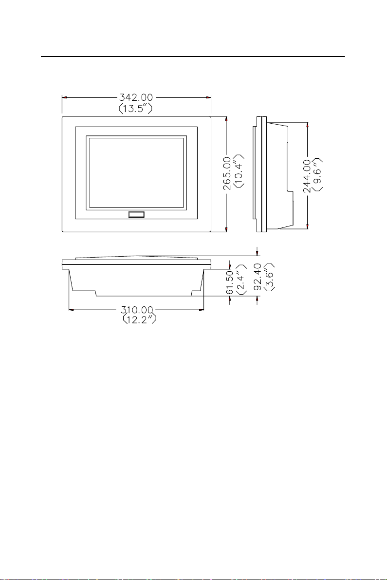
1.4 Dimensions
Figure 1.1: PPC-L106T panel PC dimensions
6 PPC-L106T User Manual
Page 15
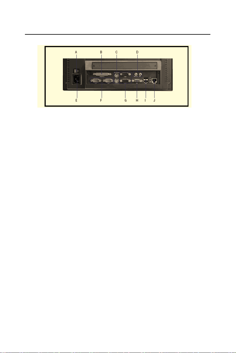
1.5 I/O Arrangement
Figure 1.2: PPC-L106T back panel I/O arrangement and cable connec-
tions
A. Power switch F. COM ports
B. Parallel port G. COM ports
C. PS/2 mouse connector H. VGA port
D. Mic-in/Line-out I. USB ports V2.0
E. AC inlet J. Ethernet
* Three RS-232 (COM1, 3, 4) and one RS-232/422/485 (COM2)
Chapter 1 General Information 7
Page 16
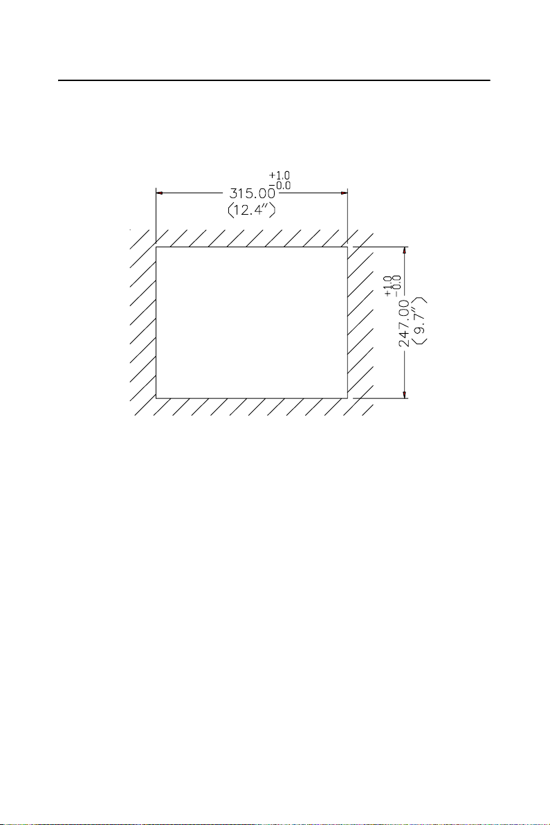
1.6 Cutout (Suggestion)
The PPC-L106T will stand on a shelf or a table, or you can mount it into
a panel. Cutout panel dimensions are as follows
Figure 1.3: PPC-L106T panel mounting cutout
8 PPC-L106T User Manual
dimensions
Page 17
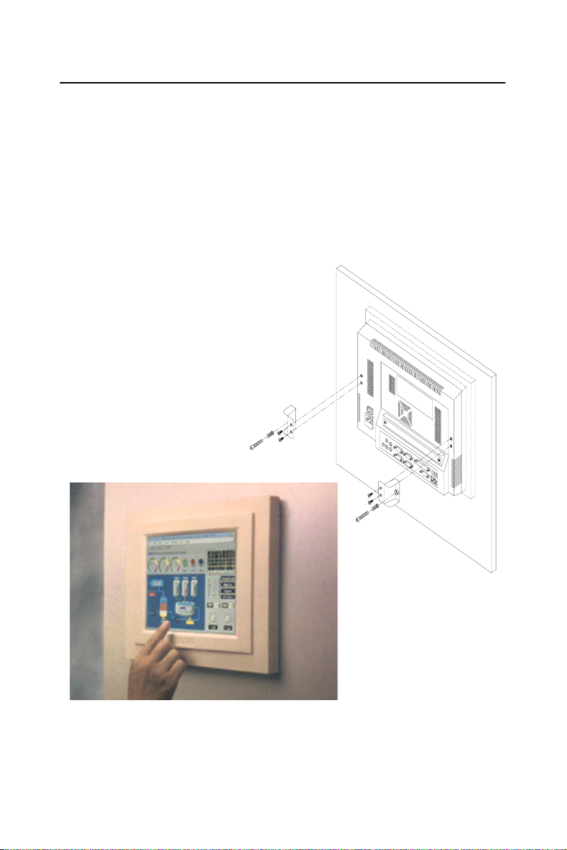
1.7 Mounting
1.7.1 Panel mounting
If you decide to use a cutout within a panel to mount your PPC-L106T,
we have included two panel-mount brackets. The brackets have two
screws that fit in the keyhole slots on the panel PC.
Slide the PPC-L106T backwards into the panel opening. Attach the two
mounting brackets by sliding the two screw heads into the keyhole slots
on the rear cover. Secure the PPC-L106T against the back of the panel
opening.
Figure 1.4: PPC-L106T rear panel mounting brackets
Chapter 1 General Information 9
Page 18
1.7.2 Desktop stand (optional)
An optional stand is available for mounting the PPC as a desktop PC. The
PPC-L106T slides into the stand and is held in place by the screws provided. The compactness of the desktop-mounted PPC-L106T saves desk
space.
Figure 1.5: PPC-L106T desktop stand
10 PPC-L106T User Manual
Page 19

1.7.3 Wall-mounting (optional)
An optional wall-mounting attachment is also available for mounting the
PPC at approximately 45° to a flat surface. Installation instructions follow:
1. The wall-mounting attachment is comprised of three parts: one
back bracket, one support bracket, and one mounting bracket.
2. First attach the back bracket to the rear cover of the PPC-L106T,
securing it in place with four of the philips-head screws provided.
3. Using a flat-head screwdriver, attach the support bracket to the
back bracket using four of the flat-head screws provided, two on
either side of the support bracket. The sides of the support bracket
should overlap the sides of the back bracket, and the screws should
secure one bracket to the other through the existing holes drilled
into each bracket.
4. Mount the mounting bracket on the wall or other flat surface. The
support bracket slides vertically from the top into the mounting
bracket. It can then can be secured to the mounting bracket by
screwing one of the philips-head screws provided through the corresponding holes at the tops of the mounting bracket and the support bracket.
Figure 1.6: PPC-L106T wall mounting configuration
Chapter 1 General Information 11
Page 20

12 PPC-L106T User Manual
Page 21

System Setup
Sections include:
• General
• Removing Rear Panel
• Installing Options
• Installing I/O Equipment
• Installing Software to the HDD
• Exploded Diagram
• PCM-9679 and I/O Adapter
• Replacement
• Power Supply and Cooling Fan
• Replacement
CHAPTER
2
Chapter 2 System Setup 13
Page 22

Chapter 2 System Setup
2.1 General
The PPC-L106T consists of a PC-based industrial computer that is
housed in a protective cover. Your HDD, DDR RAM and power supply
and are all readily accessible by removing the rear panel. Any maintenance or hardware upgrades can be carried out easily after removing the
rear panel.
Warning! Do not remove the rear cover until you have
verified that no power is flowing within the PPCL106T. Power must be switched off, and the
power cord must be disconnected. Every time
you service the PPC-L106T, you should be
aware of this.
2.2 Preparing For First Time Use
Before you set up the PPC-L106T system, you should have at least the
following items ready:
• Power cord (in the accessory box)
• PS/2 keyboard
• PS/2 mouse (for system software installation, i.e. MS Windows,
NT, etc.)
14 PPC-L106T User Manual
Page 23

2.3 Installing Options
2.3.1 Removing Rear Panel
Unscrew the eleven screws that secure the rear cover, then remove the
cover.
Figure 2.1: Removing the rear panel
Chapter 2 System Setup 15
Page 24

2.3.2 Installing a primary 2.5" HDD (internal)
You can attach one enhanced Integrated Device Electronics (IDE) hard
disk drive to the PPC-L106T's internal controller which uses a PCI localbus interface. The advanced IDE controller supports faster data transfer
rates and allows the IDE hard drive to exceed 528 MB. The following are
instructions for installation:
1. Detach the rear panel and remove.
2. Place the HDD in the appropriate location inside the PPC-L106T,
and tighten the screws.
3. Connect the cable included in this package (1x44-pin to 1x44-pin)
from the HDD to the PC board (CN9). Make sure that the red/blue
wire corresponds to pin 1 on the connector, which is labeled on the
board. Plug the other end of the cable into the enhanced IDE hard
drive, with pin 1 on the cable corresponding to pin 1 on the hard
drive.
Warnings! (1) Plug the other end of the cable into the
HDD, with pin 1 on the cable corresponding to
pin 1 on the hard drive. Improper connection
will damage the HDD.
(2) Be careful not to damage the CPU board
with your tools!
Figure 2.2: Installing a primary 2.5" HDD (internal)
16 PPC-L106T User Manual
Page 25

2.4 Installing I/O Equipment
2.4.1 PS/2 keyboard and PS/2 mouse
The PPC-L106T provides a PS/2 keyboard connector that supports a PS/2
style keyboard and a 5-pin DIN keyboard extension cable. In most cases,
especially in embedded applications, a keyboard is not used. The standard
PC/AT BIOS will report an error or failure during power-on self-test
(POST) after a reset if the keyboard is not present. The BIOS standard
setup menu allows you to select* "All, But Keyboard" under the "Halt
On" selection. This allows no-keyboard operation in embedded system
applications without the system halting under POST. Note that the mouse
port on the PPC-L106T is a PS/2 mouse port.
Note: “All but keyboard” is the default setting.
2.4.2 Mic-in, line-out
The PPC is equipped with a high quality audio interface, which provides
16-bit CD quality recording and playback as well as OPL3 compatible
FM music. It is supported by all major operating systems and is completely compatible with Sound Blaster Pro.
The audio interface includes two jacks: microphone-in and line-out (See
Fig. 1-2).
2.4.3 External VGA
The PPC-L106T can be connected to an external CRT monitor. To connect an external CRT monitor, connect the monitor's VGA cable to the
PPC-102's VGA port and connect the monitor's power cable to an AC
outlet. The PPC-L106T's external CRT display (VGA) connector is a
standard 15-pin D-SUB connector commonly used for VGA.
2.4.4 Four serial COM ports
Many available peripherals, such as a serial mouse or an optional touchscreen, require connection to a serial port. When an optional touchscreen
is ordered with a PPC-L106T, it shares COM4, and COM4 is not available as a serial port.
Chapter 2 System Setup 17
Page 26

2.4.5 Ethernet
The PPC-L106T is equipped with a high performance 32-bit Ethernet
chipset which is fully compliant with the IEEE 802.3 100 Mbps CSMA/
CD standards. It is supported by major network operating systems. It is
also both 100Base-T and 10Base-T compatible. The medium type can be
configured via the RSET8139.EXE program included on the utility disk.
The Ethernet port provides a standard RJ-45 jack. The network boot feature can be utilized by incorporating the boot ROM image files for the
appropriate network operating system. The boot ROM BIOS files are
combined with system BIOS, which can be enabled/disabled in the BIOS
setup.
2.4.6 USB ports
The external USB device may be connected to the system though the 4pin USB ports located on the rear side of the system unit.
The USB ports support hot plug-in connection. You should install the
device driver before you use the device.
2.5 Installing Software to the HDD
Installing software requires an installed HDD. Software can be loaded in
the PPC-L106T using any of four methods:
2.5.1 Method 1: Use the Ethernet
You can use the Ethernet port to download software to the HDD.
2.5.2 Method 2: Use a USB Disk or USB CD-ROM
You can use a USB disk or USB CD-ROM to download the software to
your HDD.
2.5.3 Method 3: Use the COM or parallel port
Connect another PC to the PPC-L106T with an appropriate cable and
transmit the software to the PPC-L106T.
18 PPC-L106T User Manual
Page 27
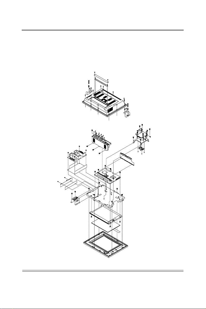
2.6 Exploded Diagram
Figure 2-3 shows all the components and parts that make up the PPCL106T. Use it as a guide when assembling and disasesembling your system.
Figure 2.3: PPC-L106T exploded diagram
Chapter 2 System Setup 19
Page 28

2.7 PCM-9679 and I/O Adapter Replacement
To replace or service the PCM-9679 (all-in-one CPU board) and I/O
adapter, complete the following steps:
1. Turn off the power to the PPC-L106T
2. Remove the rear protective cover (see Figure 2-1)
3. Install the PCM-9679 in the panel and screw in the eight screws
(see Figure 2-4)
4. When the PCM-9679 is mounted in the panel, plug and press the
adapter into the socket (see Figure 2-4))
5. Some screws on the left connect the I/O adapter to the PC, and also
connect the adapter to the PCM-9679. Screw the screws into the
panel..
Note: You may change the jumper settings for RS-
232/422/485 before installing the PCM-9679
and I/O adapter
20 PPC-L106T User Manual
Page 29

Figure 2.4: Installing/removing the PCM-9679 & I/O adapter
Chapter 2 System Setup 21
Page 30

22 PPC-L106T User Manual
Page 31

3
CHAPTER
The Engine of the
PPC-L106T (PCM-9679)
Sections include:
• Introduction
• Features
• Jumpers and Connectors
• CMOS clear
• Watchdog timer configuration
• COM2 RS-232/422/485setting
Chapter 3 System Setup 23
Page 32

Chapter 3 The Engine of the PPC-L106T
(PCM-9679)
3.1 Introduction
The PCM-9679 is a highly reliable single board computer based on the
AMD LX800 CPU. It offers built-in functionality comparable to a complete industrial PC system, including a VGA/LCD controller, network
communications, CompactFlash disk in a small 8" x 5.75" form factor.
For maximum performance, the PPC-L106T also supports a DDR
SODIMM socket that can accept up to 1024 MB memory. On-board features include an Ethernet interface, audio interface, socket for CompactFlash card, Enhanced IDE interface that supports the Ultra DMA
protocol, one parallel port, four serial ports (RS-232 and RS-232/422/
485) with DB-9 connectors, and a mini-DIN PS/2 keyboard/mouse inter-
face. An SVGA/LCD display controller (for LCD and CRT displays)
allows LCD screen resolutions up to 800 x 600 @ 256 K colors.
The PCM-9679 complies with the "Green Function" standard and supports three types of power saving features: Normal, Doze and Sleep
modes.
The display type configuration is done through software. A single Flash
chip holds the system BIOS and the VGA BIOS. This minimizes the
number of chips and eases configuration. You can change the display
BIOS simply by programming the Flash chip.
Flash memory also offers faster data access and longer MTBF than
mechanical disk drives and is an ideal solution for critical commercial or
industrial applications. The watchdog timer ensures the system will be
reset if it stops due to a program bug or EMI problem.
24 PPC-L106T User Manual
Page 33

3.2 Features
• Ultra-compact size single board computer as small as a 3 1/2" hard
disk drive (145 mm x 102 mm)
• On-board AMD LX800 CPU
• Up to 1024 MB system memory via an SODIMM (DDR)
• On-board VGA/LCD controller
• On-board 10/100Base-T Ethernet interface (dual LAN Optional)
• Supports on-board CompactFlash™ socket
• Built-in Enhanced IDE (AT bus) hard disk drive interface
• Four serial ports: three RS-232, one RS-232/422/485 or infared selectable
• Supports One Mini PCI socket
• Supports 4 USB 2.0 (2 external, 2 internal)
• Supports 8 bit GPIO
Chapter 3 System Setup 25
Page 34
3.3 Jumpers and Connectors
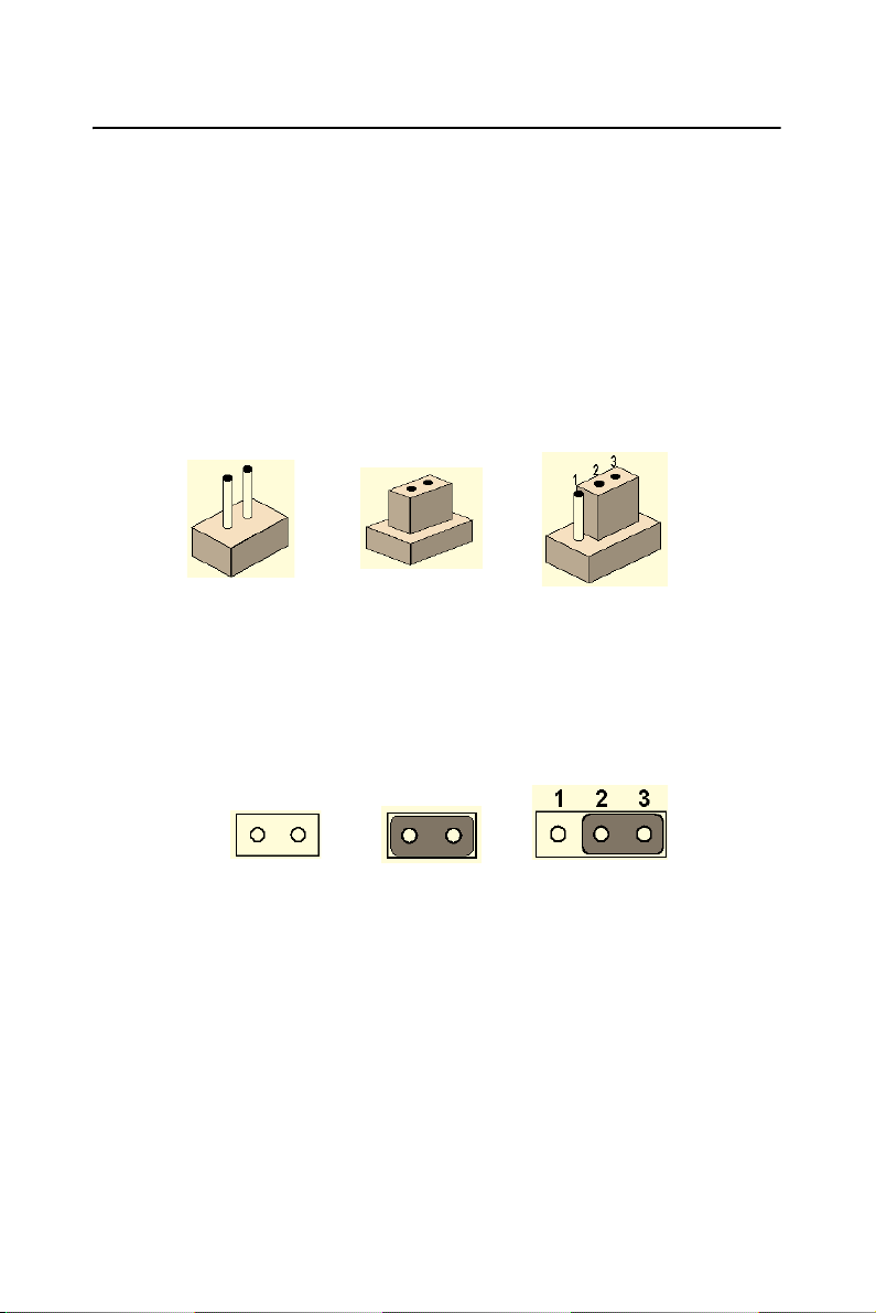
3.3.1 Setting jumpers
You can configure your panel PC to match the needs of your application
by setting jumpers. A jumper is the simplest kind of electrical switch. It
consists of two metal pins and a small metal clip (often protected by a
plastic cover) that slides over the pins to connect them. To “close” a
jumper, you connect the pins with the clip. To “open” a jumper you
remove the clip. Sometimes a jumper will have three pins, labeled 1, 2,
and 3. In this case, you would connect either pins 1 and 2 or pins 2 and 3.
The jumper settings are schematically depicted in this manual as follows:
open closed closed 2-3
A pair of needle-nose pliers may be helpful when working with jumpers.
open closed closed 2-3
If you have any doubts about the best hardware configuration for your
application, contact your local distributor or sales representative before
you make any changes.
26 PPC-L106T User Manual
Page 35

3.3.2 Jumpers
The table below lists the function of each of the board’s jumpers.
Table 3.1: Jumpers and their functions
S1 Reset Button
J2 SMBUS Power Setting
J3 CMOS Clear
J4 AT/ATX Setting
J6 COM2 RS232/422/485 Setting
J7 COM3/4 Pin9 output type setting
BT1 Battery Connector
SLOT1 PCI/ISA bus expansion connector
3.3.3 Connectors
The table below lists the function of each of the board's connectors.
Table 3.2: Panel PC connectors
Label Function
J1 Inverter power connector
J2 Flat panel display connector
J3 Primary IDE hard drive connector
J4 Keyboard connector
J5 Internal touchscreen connector
CN1 SODIMM socket
CN2 CompactFlash Disk secondary IDE connector
CN3 CD IN
CN4 I/O board connector
CN5 I/O board connector
CN6 Power FAN power connector
CN7 External KBT2
CN8 CPU FAN power connector
CN10 Power Switch
CN20 Speaker and Microphone connector (Reserved)
PS1 Power test connector (Reserved)
JS2 Brightness VR (Reserved)
Chapter 3 System Setup 27
Page 36

TOUCH-(COM4)
SMBUS
CN5
CN1
H2
J2
SMB_PWRSEL
GPIO
CN7
CN6
CN9
IDE
H4
INTERNAL USB
CN12
MIO-(USB+COM3)
CN14
MIO_(USB)
CN15
CN16
INTERNAL
AUDIO OUT
INTERNAL
SPAKER
H9
CN21
CN20
LINE_IN
J3
J4
SLOT1
CN3
H1
INVERTER
CN4
POWER INPUT
CN8
PWR_LED
S1
H5
CN17
INTERNAL LAN
H8
U12
J3
Clear CMOS
CN11
Reset Button
BT1
J4
AT/ATX Sel
SLOT1
H3
LVDS
CN2
32198765417161514131211
10
A
B
C
D
E
F
G
H
J
K
L
M
N
P
R
T
U
CN13
IAS-5V/
-12VINPUT
H6
J6
J7
CN18
CN19
J6 J7BT1
Figure 3.1: Jumpers on the PPC-L106T motherboard
J2
CN3
H1
CN4
CN8
CN11
INVERTER
CN4
POWER INPUT
CN8
PWR_LED
H5
CN17
INTERNAL LAN
CN17
H8
Figure 3.2: Connectors on the PPC-L106T motherboard
28 PPC-L106T User Manual
U12
J3
Clear CMOS
CN11
Reset Button
BT1
J4
AT/ATX Sel
SLOT1
J6
CN19 CN18
CN2CN3 CN5
H3
LVDS
CN2
12 3 4 5 67 8 9 10111213 14151617
A
B
C
D
E
F
G
H
J
K
L
M
N
P
R
T
U
CN13
IAS-5V/
-12VINPUT
H6
J7
CN18
CN19
CN1
SMBUS
TOUCH-(COM4)
CN5
CN1
H2
J2
SMB_PWRSEL
CN6
GPIO
CN7
CN7
CN6
IDE
CN9
H4
INTERNAL USB
CN14
MIO-(USB+COM3)
MIO_(USB)
CN15
INTERNAL
SPAKER
CN21
CN20
LINE_IN
CN9
CN12
CN12
CN13
CN16
INTERNAL
AUDIO OUT
H9
CN21
CN20
Page 37

3.4 CMOS Clear for External RTC (J3)
Warning! To avoid damaging the computer, always turn off
the power supply before setting “Clear CMOS”.
Set the jumper back to “Normal operation” before
turning on the power supply.
This jumper is used to erase CMOS data and reset system BIOS information.
The procedure for clearing CMOS is:
1. Turn off system.
2. Short pin 2 and pin 3.
3. Return jumper to pins 1 and 2.
4. Turn on the system. The BIOS is now reset to its default setting.
Table 3.3: CMOS clear (J3)
*Normal operation Clear CMOS
* default setting
3.5 COM Port Interface (J6, J7)
The panel PC provides four serial ports (COM1, 3, 4: RS-232; COM2:
RS-232/422/485) in one COM port connector.
3.5.1 COM2 RS-232/422/485 setting (J6)
COM2 can be configured to operate in RS-232, RS-422, or RS-485 mode.
This is done via J6.
Chapter 3 System Setup 29
Page 38

Table 3.4: COM2 RS-232/422/485 setting (J6)
*RS-232
RS-422
RS-485
* default setting
The IRQ and the address ranges for COM1, 2, 3, and 4 are fixed. However, if you wish to disable the port or change these parameters later you
can do this in the system BIOS setup. The table overleaf shows the
default settings for the panel PC’s serial ports.
COM1 and COM2 are one set. You can exchange the address range and
interrupt IRQ of COM1 for the address range and interrupt IRQ of
COM2. After exchanging, COM1's address range is 3F8 ~ 3FF and its
request IRQ is IRQ4: and COM2's address range is 2F8 ~ 2FF and its
interrupt IRQ is IRQ3.
COM3 and COM4 are another set. Their address and IRQ is the same as
the COM1/COM2 set
30 PPC-L106T User Manual
Page 39
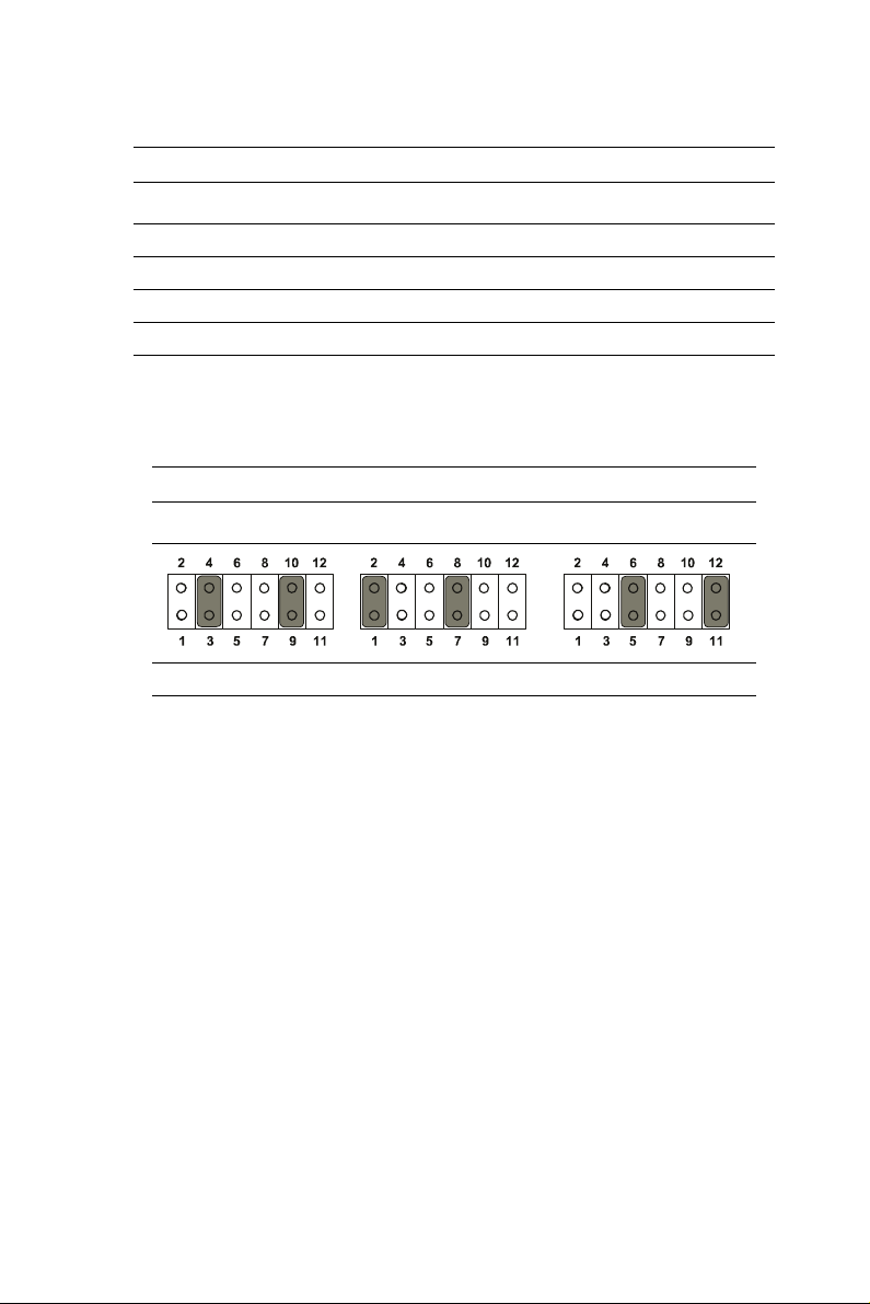
Table 3.5: Serial port default settings
Port Address Range Interrupt
COM1 3F8 ~ 3FF IRQ4
COM2 2F8 ~ 2FF IRQ3
COM3 3E8 ~ 3EF IRQ10
COM4 2E8 ~ 2EF IRQ5
3.5.2 COM3/COM4 pin 9 output setting (J7)
Table 3.6: COM3/4 pin 9 settings (J7)
*Normal operation +5 V output +12 V output
*default setting
Chapter 3 System Setup 31
Page 40

32 PPC-L106T User Manual
Page 41

A
APPENDIX
I/O Pin Assignments
Sections include:
Appendix A I/O Pin Assignments 41
Page 42

Chapter A I/O Pin Assignments
A.1 Keyboard connector (CN5-1)
Table A.1: Keyboard connector
Pin Signal
1KB_DT
2N/A
3GND
4+5 V
5KB_CK
6N/A
A.2 Mouse connector (CN5-2)
Table A.2: Mouse connector
Pin Signal
1MS_DT
2N/A
3GND
4+5 V
5MS_CK
6N/A
42 PPC-L106T User Manual
Page 43

A.3 VGA connector (CN6)
Table A.3: VGA connector
Pin Signal
1RED
2 GREEN
3BLUE
4N/A
5GND
6GND
7GND
8GND
9N/A
10 GND
11 N /A
12 N/A
13 HSYNC
14 VSYNC
15 N/A
6
111
212
313
414
515
10
A.4 COM1 RS-232 serial port (CN1-2)
Table A.4: COM1 RS-232 serial port
Pin Signal
1 DCD
2RxD
3TxD
4DTR
5GND
6DSR
7RTS
8CTS
9RI
Appendix A I/O Pin Assignments 43
1
2
3
4
5
6
7
8
9
Page 44

A.5 COM3 RS-232 serial port connector (CN2-1)
Table A.5: COM3 RS-232 serial port
Pin Signal
1 DCD
2RxD
3TxD
4DTR
5GND
6DSR
7RTS
8CTS
9RI
1
2
3
4
5
A.6 COM4 RS-232 serial port connector (CN2-2)
Table A.6: COM4 RS-232 serial port
Pin Signal
1 DCD
2RxD
3TxD
4DTR
5GND
6DSR
7RTS
8CTS
9RI
6
7
8
9
44 PPC-L106T User Manual
Page 45

A.7 COM2 Connector
Table A.7: COM2
Pin RS-232 RS-422 RS-485
1 DCD TX- DATA-
2RX TX+ DATA+
3 TX RX+ ---
4 DTR RX- ---
5 GND GND ---
6 DSR --- ---
7 RTS --- ---
8 CTS --- ---
9 RI --- ---
Appendix A I/O Pin Assignments 45
Page 46

A.8 Parallel port connector (CN1-1)
Table A.8: Parallel port connector
Pin Signal
1 STROBE*
2D0
3D1
4D2
5D3
6D4
7D5
8D6
9D7
10 ACK*
11 BUSY
12 PE
13 SLCT
14 AUTOFD*
15 ERR*
16 INIT*
17 SLCTINI*
18 GND
19 GND
20 GND
21 GND
22 GND
23 GND
24 GND
25 GND
14
15
16
17
18
19
20
21
22
23
24
25
1
2
3
4
5
6
7
8
9
10
11
12
13
* active low
46 PPC-L106T User Manual
Page 47

A.9 GPIO Connector (Default: No Load)
Table A.9: CN7 GPIO
Pin Signal Pin Signal
1+V52GPIO4
3 GPIO0 4 GPIO5
5 GPIO1 6 GPIO6
7 GPIO2 8 GPIO7
9GPIO310GND
A.10 USB 3 / USB 4 Connector (Internal)
Table A.10: CN12 Internal USB 3 / USB 4
Pin Signal Pin Signal
1 +V5_USB1 2 +V5_USB1
3 USB2_Z_P+ 4 USB3_Z_P+
5 USB2_Z_P- 6 USB3_Z_P-
7GND8GND
9GND
Appendix A I/O Pin Assignments 47
Page 48

A.11 SMBUS Connector (Default :No Load)
1
2
3
4
Table A.11: CN5 SMBUS Input
Pin Signal
1 +V_SMB
2GND
3 SMB_A_CLK
4SMB_A_DAT
48 PPC-L106T User Manual
 Loading...