

Page 1
Qí
Ш
Z
AWM093HX
AWM123HX
о
ь
Û
Z
о
U
—
<
Q_
CO
AOM183HX
(match AWM093HX+AWM093HX)
U
_ AOM243HX
Installation manual (match AWM123HX+AWM123HX or AWM093HX+AWM123HX)
www.amcorgroupusa.com
Page 2

Page 3
Foreword
This instruction Manual is the universal-purpose version for the models of separate wall-mounted
air conditioners manufactured by our Co.The appearance of the units that you purchase might be
slightly different from the ones described in the Manual, but it does not affect your proper
operations and usage.
Please read carefully the sections corresponding to the specific model you choose,and keep the
Manual properly so as to facilitate your reference at later time.
IMPORTANT!
Please Read Before Starting
This air conditioning system meets strict safety and operating standards.
As the installer or service person , it is an important part of your job to install or service the system
so it operates safely and efficiently.
For safe installation and trouble-free operation.you must:
• Carefully read this instruction booklet before beginning.
• Follow each installation or repair step exactly as shown.
• Observe all local,state,and national electrical codes.
• Pay close attention to all danger,warning,and caution notices given in this manual.
WARNINGiThis symbol refers to a hazard or unsafe practice which can result in severe personal
injury or death.
CAUTION:This symbol refers to a hazard or unsafe practice which can result in personal injury
and the potential for product or property damage.
CONTENTS
SELECTING THE MOUNTING POSITION 1
INSTALLATION DIAGRAM OF INDOOR UNITS 2
FINISHING 6
FRONT PANEL REMOVALAND INSTALLATION 8
LOCATION OF OUTDOOR UNIT 9
ELECTRICAL CONNECTION BETWEEN OUTDOORAND INDOORUNIT 10
INSTALLATION/SERVICE TOOLS (ONLY FOR R41OA PRODUCT 12
REFRIGERANTTUBING 14
THE INTRODUCTION OF THE ROTATIONAL ADAPTER: 15
AIRPURGING 16
SELF DIAGNOSIS FUNTIONS 18
WIRE DIAGRAM 19-21
Page 4
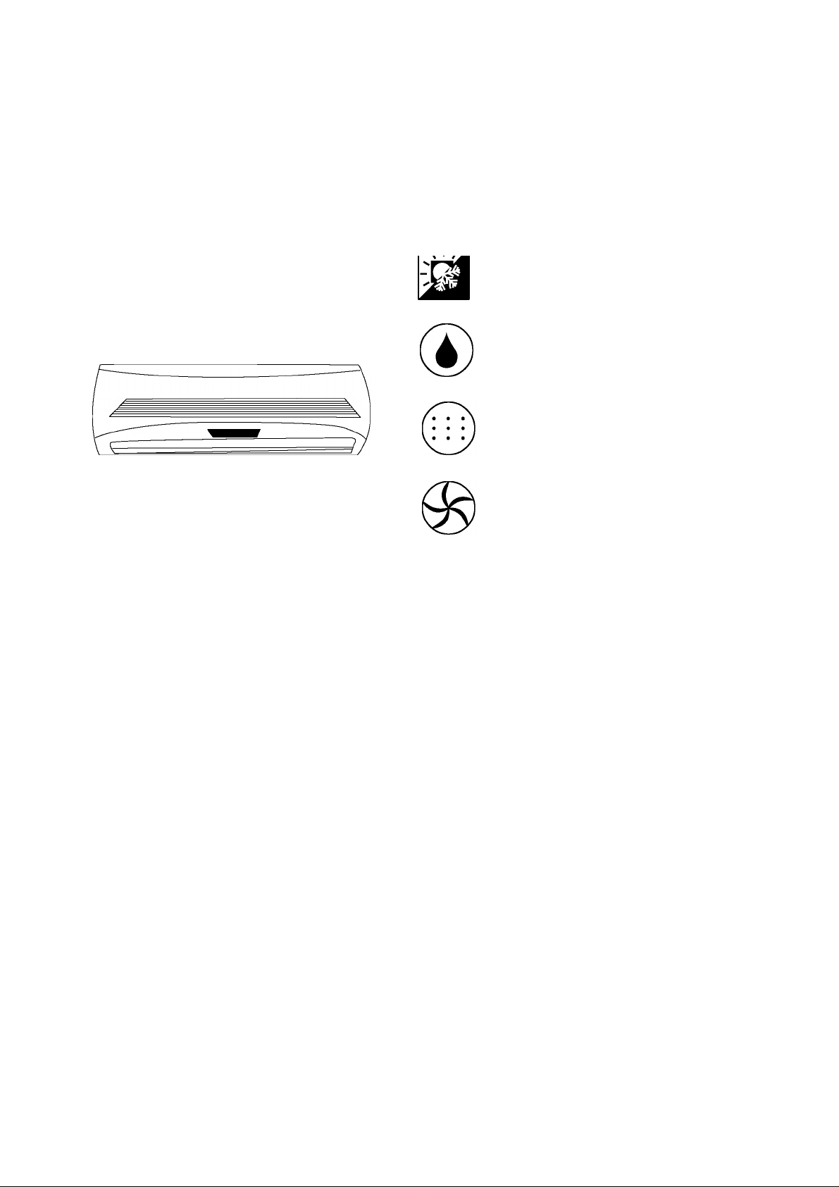
This Split Air Conditioner is designed for versatile
application :
Cooling & Heating
Dehumidifying
Ventilation
Filtration
IMPORTANT NOTICE :
• This air œnditioner must be grounded to protect against electrical
shock.
• Installation of the air conditioner must be performed by an
experienced air conditioning installer, observing good
refrigeration practice.
• Failure to comply with the manufacturer's installation and
operation installation and operation instructions could affect
the performance of the air conditioner and the validity of the
warranty.
Page 5

SELECTING THE MOUNTING POSITION
Decide the mounting position with the customer as
foilows:
INDOOR UNIT
(1 ) Install the indoor unit level on a strong wall which is not subject
to vibration.
(2) The inlet and outlet ports should not be obstructed : the air
should be able to blow all over the room.
(3) Do not install the unit where it will be exposed to direct sunlight.
(4) Install the unit where connection to the outdoor unit is easy.
(5) Install the unit where the drain pipe can be easily installed.
(6) Take servicing,etc.into consideration and leave the spaces
shown in figure. Also install the unit where the filter can be
removed.
!\ WARNING
Install at a place that can withstand the weight of the indoor
and outdoor units and install positively so that the units will
not topple or fall.
CAUTION
(1) Do not install where there is the danger of combustible gas
leakage.
(2) Do not install near heat sources.
(3) If children under 10years old may approach the unit, take
preventive measures so that they cannot reach the unit.
Page 6
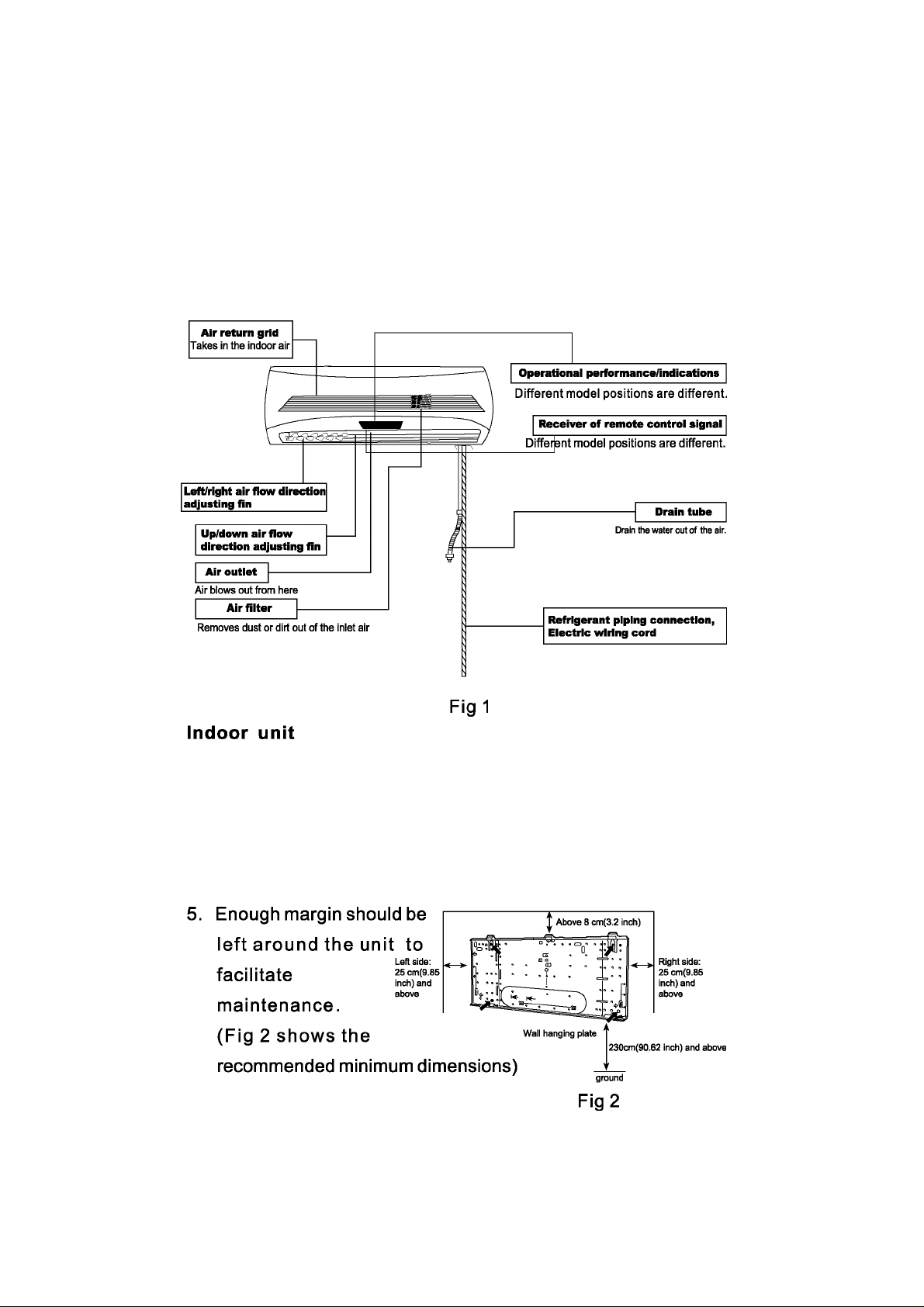
INSTALLATION DIAGRAM OF INDOOR UNITS
Wall-mounted Type
1. Firmly install it on the rigid wall.
2. The air intake and outlet vents should be unblocked, and the
cold air can be blown to the whole room.
3. Away from thermal sources or sources of combustible gases.
4. Not exposed to direct sunlight.
Ceiling
Page 7
Installation of wall-mounting plate
Fix the wall-mounting plate firmly on the wall with screws.Make
sure of the leveling of the place. Slanted wall-mounting plate
might jeopardize the smooth discharge of condensed water.
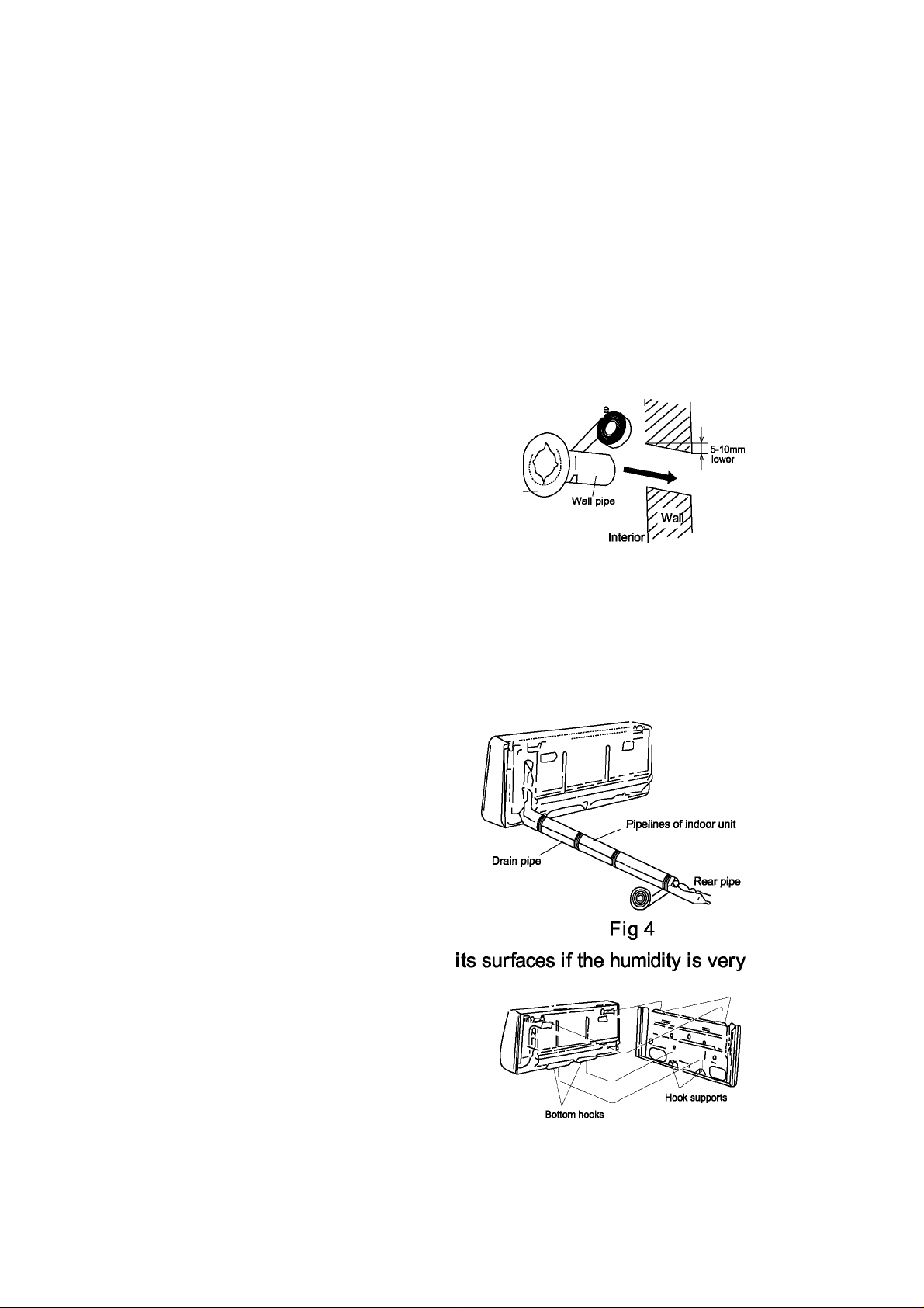
1. Drill holes on the wall
Drill holes places slightly below the wall-mounting plate,with
hole diameter of 65mm and the outer
Fix with a tapi
edge of the hole 5-10mm lower (
Fig3) so that the condensed water
can smoothly flow out. Cut the waiicap-
wall penetrating pipe to proper
length according to the thickness
Fig3
/1 Exterior
of the wall(3-5mm longer than
the wall thickness)and insert the pipe as indicated in Fig 4.
2. Installation of drain pipe
Install the pipelines of the indoor unit in accordance with the
direction of the wall holes.
Wrap tightly the drain pipe
and the pipelines with tape.
Make sure that the drain pipe
is underneath the pipelines ,
(Fig 4)(When the drain pipe
passes the room interior, so me
condensed water might occur to
high).
3. Installation of indoor unit pass
the connection wires,connecting
pipelines and drain pipe through
the wall hole.Hang the indoor unit pjg 5
Top hooks
Page 8
on the hooks at the top of the wall-mounting plate so that the
hooks at the bottom of the indoor unit match the hooks of the
wall-mounting plate. (Fig 5)
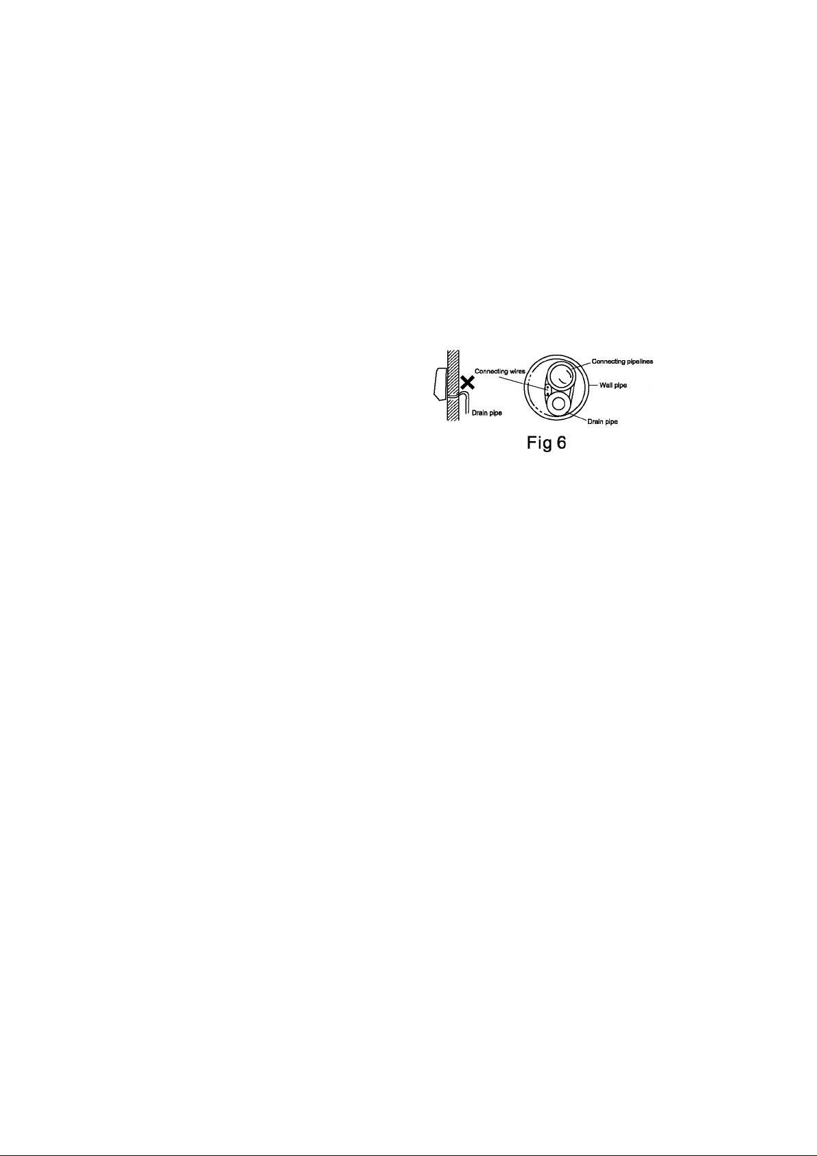
Inspections:
a. See if the hooks at the top and bottom are firmly fixed.
b. See if the position of the master unit is
properly leveled.
c. The drain pipe should not curve
upward( Fig 6).
d. The drain pipe should be at the
lower part of the wall pipes(Fig 6).
4. Wire connections of indoor and outsoor units connect the wires
of the indoor and outdoor units properly according to the schematic
diagram.
Note: Do not connect the wires in a wrong way, otherwise electric
malfunctions will be caused and ever damages to the units will
occur.
The appliance is fitted with means for disconnection from the
supply mains having a contact separation in all poles that provide
full disconnection under over voltage category III conditions,
and these means must be incorporated in the fixed wiring in
accordance with the wiring rules.
Page 9
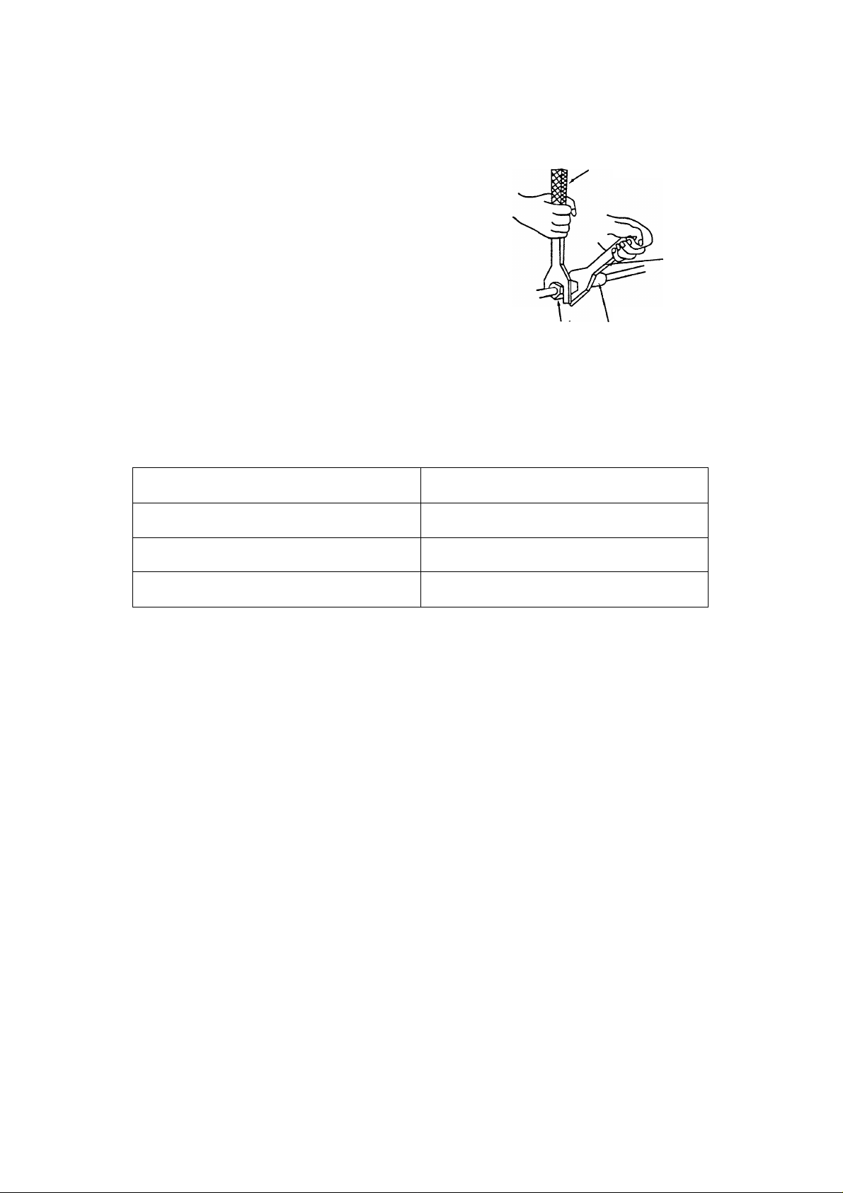
Installation of the connection pipe
1. Align the center of the piping flare
with the relevant valve.
Torque wrench
2. Screw in the flare nut by hand and
Spanner
then tighter the nut with spanner and
torque wrench refer to the diagram
at right.
Nut of
connection pipe
Fig?
Joint
Note: Exceeding tightening torque will damage the flare surface.
Tightening torque table
Hex nut diameter
4>6mm(1/4")
4)9.5mm(3/8")
4)12mm(1/2 ")
Tightening torque(N.m)
15-20
31-35
50-55
Page 10

FINISHING
1. Insulate between pipes.
• For rear,right,and beween piping,overlap
the connection pipe heat insulation and
indoor unit pipe heat insulation and bind
them with vinyl tape so that there is no gap.
• Forleftand left rear piping,butthe connection
pipe heat insulation and indoor unit pipe
heat insulation together and bind them
with vinyl tape so that there is no gap .
• For left and left rear piping , bundle the
(Saddle)
P i pe
piping and drain hose together by wrapping
them with cloth tape over the range within
which they fit into the rear piping hosing
section.
2. Temporarily fasten the connection cord
along the connection pipe with vinyl tape.(
Wrap to about 1/3 the width of the tape
the bottom of the pipe so that water does not
enter.)
3. Fasten the connection pipe to the outside
wall with a saddle etc.
4. Fill the gap between the outside wall pipe
hole and the pipe with sealer so that rain
water and wind cannot blow in.
Connection^^e
So that there is no gap.
P i pe
(Outdoors)
Over lapthe insulation
vinyl tape
with
0 I oth tape
Cloth tape
5. Fasten the drain hose to the outside wall,
etc.
©
Page 11

For connection from the left rear Check the following: View from indoors
BAD BAD
©
Page 12

FRONT PANEL REMOVAL AND INSTALLATION
AIR CLEANING UNIT REMOVAL
1. Open the intake grille ,and then remove the right air filter.
2. Pull the air cleaning unit grip in the direction of the arrow and
remove the unit.
AIR CLEANING UNIT INSTALLATION
1. Open the intake grille, and then insert the dust collection unit
into the indoor unit.
2. Install the right air filter, and then close the intake grille.
THE INTAKE GRILLE REMOVAL
1. Open the intake grille.
2. Pull down the knob.
3. Lift the intake grille upward, until the axle at the top of the intake
grille is removed .
THE INTAKE GRILLE INSTALLATION
1. The fixing axle of the intake grille is installed on the Panel.
2. Lay down the intake grille.
THE FRONT PANEL REMOVAL
1. Remove intake grille (Reference the intake grille removal.)
2. Remove four screws.
3. The thumb is hung on the lower part as shown in the figure ,
and it pulls to the front, pushing [ V ] mark,and bottom hooks (
two position)is removed from wall hook bracket.
4. The front panel bottom is pulled to the front, and bottom hooks
is removed indoor unit.
5. The front panel is pulled to the front, raising the upper surface,
and a front panel is removed.
THE FRONT PANEL INSTALLATION
1. Firstly, fit the lower part of the front panel,and insert top and
bottom hooks.(Three top sides, six bottom sides)
2. Four screws is attached.
3. The intake grille is attached.
Page 13

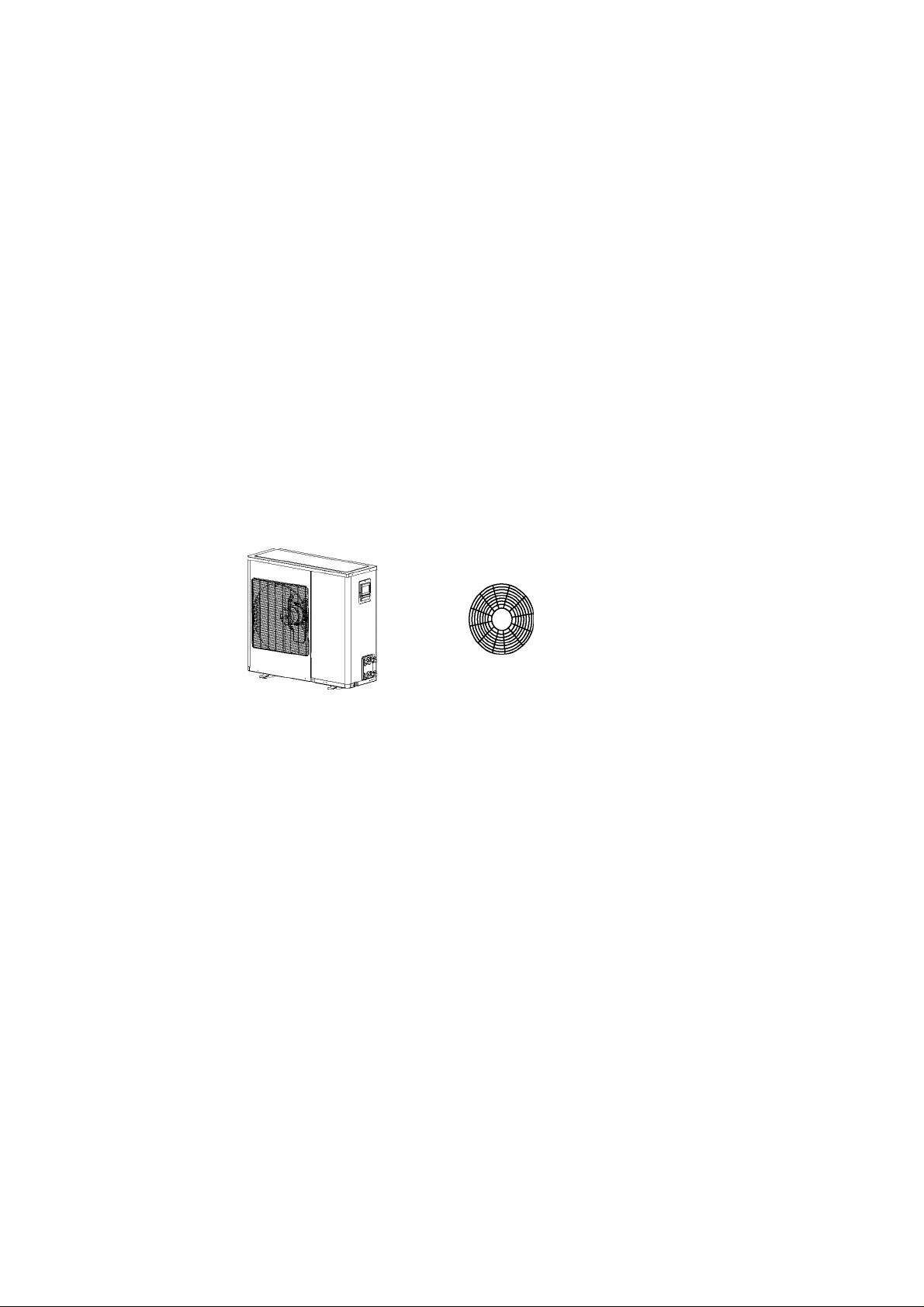
LOCATION OF OUTDOOR UNIT
Select the location considering the foiiowing:
OUTDOOR UNIT
1 .The location must allow easy servicing and provide good air circulation as shown in f i g 8.
2.The unit may be suspended from a wall by a bracked(Optional)or located in a free standing
position on the flooripreferably slightly elevated).
3.lf the unit is suspended , ensure that the bracket is firmly connected and the wall is strong
enough to withstand vibrations.
4. Unit location should not disturb neighbours with noise or exhaust air stream.
5. Place the mounting pads under the unit legs.
6. Refer to figuregfor allowed installation distances.
25mm(82FT)
L,+L2^30m(100FT)
H„H2^10m(33FT)
Fig 8
L„L„L3^25m(82FT)
L,+L2+L3^50m(164FT)
H,,H2,H3^10m(33FT)
Page 14

ELECTRICAL CONNECTION BETWEEN
OUTDOOR AND INDOOR UNIT
ELECTRICAL REQUIREMENTS
Electrical wiring and connections should be made by qualified electricians and in accordance
with local electrical codes and regulation.The air conditioner units must be grounded.
The air conditioner units must be connected to an adequate power outlet from a separate
branch circuit protected by atimedelay circuit breaker, as specified on unit's nameplate.
Voltage should not vary beyond ± 10% of the rated voltage.
1 .Remove the power supply cable that is connected to the indoor unit!
2. To connect the indoor units to the outdoor units,use the foiiowing eiectrical cabies.
Electrical connections:
Power input cable: 1 group 3wiresX14AWG
cable between indoor and
outdoor units: 2 group 4 wiresX14AWG(some modeis are 2 group 2 wiresX14AWG)
3. Prepare the cable ends for the power input and for the cables between outdoor and indoor
units as shown in figure 3a and 3b respectively.
4. Connect the cable ends to the terminals of the indoor and outdoor units , as show in fig4, figS.
Please select corresponding connection according to the different indoor units.
5.Secure the multiple wire power cable with the cable clamps.
•Power input cable
8mm
(0.315inch).
L«25m(81.9673FT)
U25m(81.9673FT)
L«25m(81.9673FT)
8mm
J
(0.315inch)
100mm
(3.937inch)
Fig 12
40mm _wR
(1.575inch)
Page 15

For North America Model: Fig 13.14
Electrical connections:
Power input cable: 1 group 3 wiresX14AWG
cable between indoor an outdoor units: 2group4wiresX14AWG
This figure adapt to AOM183HX(AWM093HX+AWM093HX)
Electrical connections:
Power input cable: 1 group 3 wiresX 14AWG
cable between indoor and outdoor units: 2 group 2 wiresXI4AWG
This figure adapt to AOM243HX(AWM123HX+AWM123HX or AWM093HX+AWM123HX)
Page 16

INSTALLATION/SERVICE TOOLS(QNLY FOR R410A PRODUCT)
CAUTION
New Refrigerant Air Conditioner Installation
This air conditioner adopts the new MFC refrigerant (R41OA) which does not destroy ozone layer.
R41 OA refrigerant is approx . 1.6 times of refigerant R22. Accompanied with the adoption of the
new refrigerant, the refrigeration machine oil has also been changed.
Therefore,during installation work, be sure that water, dust, former refrigerant, or refrigeration
machine oil does not enter into the new type refrigerant R41 OA air conditioner circuit.The system
must not be left open to the atmosphere for any reason for any period of time as the systems oil
quickly absorbs moisture and will contaminate and damage the system.
A refrigerant liquid line drier is recommended.
To prevent mixing of refrigerant or refrigerating machine oil ,the sizes of connoting sections of
charging port on main unit and installation tools are different from those used for the conventional
refrigerant units. Accordingly,special tools are required forthe new refrigerant (R410A) units.
For connecting pipes use new and clean piping materials with high pressure fitting made for
R41 OA only, so that water and/or dust does not enter. Moreover, do not use the existing piping
becausetherearesomeproblemswithpresure fittings and possible impurities in existing
piping .
Changes in the product and components
In air conditioners using R41 OA ,in order to prevent any other refrigerant from being accedentally
charged .the service port diameter size of the outdoor unit control valve (3 way valve ) has been
changed. (1/2 UFN 20 threads per inch)
• In order to increase the pressure resisting strength of the refrigerant piping ,flare processing
diameter and opposing flare nuts sizes have been changed.! fot copper pipes with nomensions
1/2 and 5/8)
Page 17

New tools for R410A
Nes tools for R410A
Chages
As the working pressure is high , it is impossible to measure the
Gauge manifold
working pressure using conventional gauges. In order to prevent
any other refrigerant from being charged,any other refrigerant
from being charged, the port diameters have been changed.
In order to increase pessure resisting strength, hose materials
Charge hose
and port sizes have been changed(to 1/2 UNF 20 threads
per inch).When puchasing a charge hose,be sure to confirm
the port size.
Electronic balance for refrigerant
charging
As working pressure is high and gasification speed is faft,
it is difficuit to read the indicated value by means of
charging cylinder ,as air bubbles occur.
The size of opposing flare nuts have been increased ,
Torque wrench (nominal dia.1/4,3/8)
incidentally,a common wrench is used for nominal
diameters 1/4 and 3/8.
Flare tooKclutch type)
By increasing the clamp bar'receiving hole size , strength
of spring in the tool has been improved.
Gauge for projection adjustment Used when flare is made by using conventional flare tool.
Connected to conventional vacuum pump,it is necessary to use an adapter
to prevent vacuum pump oil from flowing back into the charge hose , The
Vacuum pump adapter
charge hose connecting part has two ports-one for conventional refrigerant
(7/16 UNF 20 theads per inch )and one for R410A,if the vacuum pump oil (
mineraDmixes with R41OA a sludge may occur and damage the equipment.
Gas leakage detector Exclusive for MFC refrigerant
• lncidentally,the "refrigerant cylinder"comes with the refrigerant des i gnat ion (R410A)and
protector coating in the U.S's ARI specified rose color (Ari color code; PMS 507).
•Also the "charge port and packing for refrigerant cylinder"requires 1/2 UNF 20 theads per inch
corresponding to the charge pOse's port size.
Page 18

REFRIGERANT TUBING
CONNECT THE INDOORTOTHE OUTDOOR UNIT
The indoor unit contains a small quantity of nitrogen.Do not unscrew the nuts from the unit until
you are ready to
connect the tubing.The outdoor unit is supplied with suffcient refrigerant charge(R410A).Refer
to outdoor unit nameplate.
To prevent crushing,bend tubes using a bending tool.
NOTE:U se refrigeration R41OA type copper tubing only.
1 .Open the valve cover.
2. Use tubing diameter that corresponds to the tubing diameter of the indoor and outdoor units.
Note that the liquid and suction tubes have different diameters.(See tube size,torque tightening
table.)
3. Place flares nuts on tube ends before preparing them with a flaring tool.Use the flare nuts that
are mounted on the supplied outdoor and indoor units.
4. Connecttheallendsofthetubingtotheindoorandoutdoorunits.Noticethesign.AII ends
should correspond one by one.
5.Insulate each tube separately,and their unions,with at least 6mm thick of insulation .Wrap the
refrigerant tubing,drain hose and electric cables together with a vinyl tape (UV protected).
Caution!
When unscrewing the
valve caps, do not stand
in front ofthemorthe
spindles at any time,as
the system is under
pressure.
____________
Fig 15
1.INDOOR UNIT
2.Liquid tube(small dia.)
3.Suction tubedarge dia.)
4. Plugs
5. Flare nuts
6. Tubing between units
7.Suction tube
8.Liquid tube
9.OUTDOOR UNIT
10.Flare nuts
11 .Suction valve(larger)
12.Liquid valve(smal)
NOTE:1. ForunituseconnectionsA,B
and D
2. For large indoor unit of 5.0KW
Use the lower connection(unit D)
and use the 3/8"-1/2"transition(
supplied)
3. The electric control channel must
match the tube channel.
Page 19

Tightening
torques of unions
and valve caops:
TUBE SIZE TORQUE
Liquid line 1/4"
Suction line 3/8"
Suction line 1/2"
Suction line 5/8"
\
15-20 N.M.
30-35 N.M.
50-54 N.M.
75-78 N.M.
Gx.
-----
Fig 9
1. Wrench
2. Torque wrench
3. Union
i J
Fig 10
To prevent refrigerant
leakage,coat the fiared
surface with
refrigeration oil
Gr
Figli
1 .Suction valve
2.Service port
3.Liquid valve
The introduction of the rotationai adapter:
The size of two calibers of the rotational adapter isdifferent:
one is 1/2" and the other is 3/8". The rotational adapter is
applicable for aom 243HXunit, the detail can be referred to the
following figure.
Indoor unit
Page 20

Air Purging
Air andmoistureremaining in theref rigerant system have undesrable efTects asindicatedbelow.
•Pressur e inth esyste m rises.
•Ope ratingcurren t rises.
•Cooling(o rheating )efficienc ydrop s.
•Moisture inth eref rigerantcircui t mayfree zean d biockcapiiia rytubing.
•Water mayiea d tocorrosio n ofpa rts inth eref rigerationsystem.
Therefore,th eindoo runi t andtubin gbet weenth eindoo ran doutdoo r unit must beiea ideste dan d evacuated
torem ove anynoncondensa biesan dmoistur efro mth esystem.
AirpurgingWith N^cuumPump
Preparation
•Che ck that each tubing(both iiquid and gas side
tubes)bet weenth eindoo ran doutdoo runit s have
beenprope riyconnecte d andai iwi ring forth etest
run has been compieted. Remove the service
vaivecap sfro mbot hth ega san dth eiiqui dside
onth eoutdoo runit .Not etha tbot hth eiiqui dand
thega ssid ese rvice vaives onth eoutdoo runi tare
keptciose d atthi sstag e.
Leakiest
•Connect the manifoid vaive(wilh pressure
gauges) and dry nitrogen gas cyiinder to this
servicepo rtwit hcharg ehose s.
Besur e tous e amani foid vaive forair
purging, if it isno t avaiiabie,us e astop
vaive forthi spu rpose.Th e"Hi "kno bof
themani foid vaive mustai ways be kept
ciose.
•Pressurizeth esystem to nomore than150 P.S.i.G
with dry nitrogen gas and ciose the cyiinder vaive
whenth e gaugereadingreached 150 P.S.i.G. Next;
test fiorieakswithiiquidsoa p.
• Do aiea k test ofai ijoints ofth etubing(bothindoor
andoutdoor)an dbothgasan diiquidsid e service
vaives.
Bubbies indicate aieak. Besure towipeoffth esoap
with aciea ncioth.
•Afte rth esyste m is found to be free of ieate,reii eve
the nitrogenpressure byiooseningth echarg ehose
connecter atth enitrogen cyiinder.Whenth esystem
pressure isreduced tono rmai,disconnectth ehose
fromth ecyiinder.
Indoor unit
Toavodnitrogeen teingtherefigerartsysten in
ai iqud staè,thetop ofthecylindemust beh ighe
th aii ts bo ttoiw h 31 youp ressdzet he sy ste m
Usu^thecyiindeis us si in averticástandig
position
Page 21

Installation
— Soapwate rmethod
(1) Rem oveth ecap sfro mth e gassid eand
liquidsid e valves.
(2) Rem oveth ese rvice-portca pfro mth egas
side valve.
(3) Toope nth ega ssid e valvetu rnth e valve
stemcounterclo ckwiseappr oximately90 °,
wait forabou t2~ 3second s,an dclos eit.
(4) Appl y asoa p water or allqui dneut ral
detergent onth eindoo runi tconnectio nor
outdooruni tconnection s by asof t brushto
check forleakag e ofth econnectin gpoints
ofth epiping.
(5) If bubblescom eout ,th epipe s have
leakage.
-------------------------
Evacuation
•Connec tth echarg ehos een ddesc ribed inthe
precedingstep s toth e vacuumpum pto
evacuateth etubin gan dindoo runit.
Confirmth e"Lo "kno b ofth emani fold valveis
open.Then, runth e vacuumpum p.
Theope ratlontim e for evacuation varleswith
tubinglengt han dcapacit y ofth epum p.The
followingta blesh owsth etim erequire d for
evacuation.
Required time for evacuatlonwhe n 30gal/h
Iflubln glengt h Isless
thanlO m(3 3ft)
vacuumpum p isused
Iftubln glengt h Islonger
thanlO m(3 3fl)
lOmin .ormore 15min . ormore
Indoor unit
Outdoor unit
•Whe nth edesire d vacuum Isreached ,clos ethe
"Lo"kno b ofth emani fold valvean dsto pthe
vacuumpum p.
Finishing thejob
•Wit h ase rvice valvewrench ,tu rnth e valve
stem ofllqui dsid e valvecounter-cio ckwiseto
fullyope nth e valve.
• Turnth e valveste m ofga ssid e valvecounterclockwise to fullyope n the valve.
•Loose nth echarg ehos e connected toth ega s
sidese rvicepo rtsllghtly toreleaseth epressure,
theorem oveth ehos e.
•Replaceth efiare nutan d itsbonnet onth e gas
sidese rvicepo rtan d fastenth e flare nut secure^
with anadjustablewrench.Thisprocess Is very
important topreveit leakacpfro mth esystem.
•Replaceth e valve caps atbothgasan dliquid side
service valvesan d fastenthemtight.
Thiscompletesal rpurging with a vacuumpum p.
Theal rconditloner Is nowready totes t run.
Pressure
gauge
Open
Manifold valve
Close
Vacuum pump
Page 22

Self DiagnosisFuntions
Our company has provided the thoughtful services for customers, and
the air conditioner had been installed self diagnosis system to display
the code for failure.
(1) Indoor unit fault shows as following:
Failure Failure code
Communication failure
Failure of room temperature sensor.
Failure oftube-exit temperature sensor
Failure oftube-entry temperature sensor
Failure oftube-midpointtemperature sensor
Failure of PG fan F4
(2) Outdoor unit fault shows as following:
Fault Fault code
Fault ofoutdoor unit transducer module
protecting.
Outdoor unit AC input too big.
Outdoor unit compressor exhaust temperature
too high, outdoor environment temperature
ultra warm, compressor outer cover temperature
switch disconnection .
The outdoor machine direct current bus bar
is unusual in voltage.
F1
F2
F3
F3
F3
P2
P3
P4
P7
Fault of lack refrigerant or fault of reversing
valve.
Faultoftheoutdoor temperature sensor.
Fault of outdoor unit drive, fault of compressor
start.
P8
F6
FC
Page 23

AWM093HX & AWM123HX indoor wire diagram
Page 24

REACTOR
AOM183HX outdoor wire diagram
To coopretsai tupeiituiel
protector
INSTRUCTION:
COMPRESSOR:
BROWN (U),BLACK(V),BLUE(W)
WIRE COLOUR;
BL (BLUE),BK(BLACK),
BR(BROWN), RD(RED),
GR(GREEN), YL(YELLOW),
WH(WHITE), OR(ORANGE)
simulant quantity input;
IA1 :exhaust temperature (3950)
IA2:outside temperature ( 3470)
I A3: condensator midpiont temperature ( 3470)
IA4: inspiration temperature(3470)
(li>^
GIXtlD
CHOP)
CID^
BL
R
RD
EARTH
f A
-----------------------
FILTER
GR
AC-N
AC-L
^BK
GR
-«3
(DX^
(0)9(ID
(11X3®
cnx3®
Page 25

AOM243HX outdoor wire diagram
Page 26

Page 27

Page 28

Tsim Sha Tsui, Kowloon,
Hong Kong
Tel: +852 2997 6865
Fax: +852 2997 6091
Email: amcorhk@amcorgroup.com
United Kingdom
Amcor Ltd
9 Ryan Drive, West Cross Centre,
Great West Road, Brentford,
Middlesex, TW8 9ER,
United Kingdom
Tel: +44 20 8560 4141
Fax: +44 20 8232 8814
Email: amcoruk@amcorgroup.com
USA
Amcor Inc.
685A Gotham Parkway, Carlstadt,
New Jersey 07072,
United States of America
Tel: +1 201 460 8100
Fax: +1 201 460 9481
Email: amcorusa@amcorgroup.com
The Netherlands
Amcor B.V.
Anton Philipsweg 9-11,
1422 AL Uithoorn,
The Netherlands
Tel: +31 297 560 079
Fax: +31 297 523 062
Email: amcorex@amcorgroup.com
Israel
Amcor International Ltd
3 Sapir Street, Herzelia Pituach,
46733, Israel
Tel: +972 9 951 5351
Fax: +972 9 958 5650
Email: amcoril@amcorgroup.com
Singapore
Amcor Investments (Singapore) Pte Ltd
545 Orchard Road,
#13-02, Far East Shopping Centre,
Singapore 238882
Tel: +65 6297 9881
Fax: H-6s 6297 8891
Email: amcorsg@amcorgroup.com
Amcor (Guangzhou) Ltd - China
Room 2903, 29/F Renfeng Tower,
490 Tianhe Road, Tianhe District,
Gianzhou, China 510630
Tel: -1-86 20 3888 6708
Fax: -1-86 20 3888 6619
amcorgz@amcorgroup.com
Amcor Ltd - Dong Cuan, China
8/F Changwang Bldg, Dongxing Road
ChangpingTown, Dongguan City,
Guangdong Province, China
Tel: -1-8676981175780
Fax: -1-86 769 8117 5785
amcorcn@amcorgroup.com
Amcor Industries Ltd - China Factory
Xialiao village, longxi Town,
Boluo County, Huizhou City
Guandong Province, China
Tel: -1-867526879015
Fax: -1-86 752 6383 170
amcorappl@amcorgroup.com
^^1 P^US
3058080
00
VO
00
www.amcorgroupusa.com
800-584-6484
 Loading...