


Commercial Microwave—Technical Information
230V, 50 Hz Models
RMS510TS2 |
P2006703M |
RMS510DS2 |
P2006704M |
RMS510TSUA |
P2006707M |
RMS510DSUA P2006708M |
|
RMS510TSCA |
P2006709M |
RMS510TSIA |
P2006710M |
RMS510TSAA |
P2006711M |
|
|
Due to possibility of personal injury or property damage, always contact an authorized technician for servicing or repair of this unit.
Refer to Owner’s Manual for installation and operating instructions
To avoid the risk of electrical shock, personal injury or death, disconnect power to oven and discharge capacitor before servicing, unless testing requires power.
Model |
Region |
Control |
Consumption |
Power Source |
Plug Type |
RMS510TS2 |
EMEA, SEA, LATAM |
Touch |
1500 W, 7.3 A |
230v, 50hz, 16A |
CEE 7/7 “Schuko” |
RMS510DS2 |
EMEA, SEA, LATAM |
Dial |
1500 W, 7.3 A |
230v, 50hz, 16A |
CEE 7/7 “Schuko” |
RMS510TSUA |
EMEA, UK, LATAM |
Touch |
1500 W, 7.3 A |
230v, 50hz, 13A |
BS1363/A |
RMS510DSUA |
EMEA, UK, LATAM |
Dial |
1500 W, 7.3 A |
230v, 50hz, 13A |
BS1363/A |
|
|
|
|
|
|
RMS510TSAA |
Australia |
Touch |
1500 W, 7.3 A |
230v, 50hz, 10A |
Type 1 |
RMS510TSCA |
China |
Touch |
1500 W, 7.3 A |
230v, 50hz, 16A |
China |
RMS510TSIA |
India |
Touch |
1500 W, 7.3 A |
230v, 50hz, 16A |
BS546 |
|
|
|
|
|
|
Models |
RMS510D / RMS510T* |
Power Output |
|
Nominal microwave energy (IEC705) |
1000 Watts |
Minimum temperature rise (∆T) |
10º F / 5º C |
|
|
Operating Frequency |
2450 MHz |
Dimensions |
|
Cabinet |
|
Width |
508mm (20") |
Height |
311mm (12 1/4") |
Depth |
419mm (16 1/2") |
Oven Interior |
|
Width |
330.2mm (13") |
|
|
Height |
197mm (7 3/4") |
Depth |
330.2mm (13") |
Weight |
|
Crated |
14.5 kg. (39 lbs.) |
|
|
Uncrated |
17.7 kg. (32 lbs.) |
July 2019 |
1 |
©2019 ACP, Inc. |
16500066 |

Component Testing Procedures
To avoid risk of electrical shock, personal injury or death, disconnect power to oven and discharge capacitor before servicing, unless testing requires power.
|
Illustration |
Component |
Test |
Results |
|||||
|
|
|
|
|
|
|
Thermal Cutout |
Disconnect all wires from TCO. |
|
|
|
|
|
|
|
|
|
Measure resistance across terminals. |
|
|
|
|
|
|
|
|
|
|
|
|
|
|
|
|
|
|
|
|
|
|
|
|
|
|
|
|
|
Cavity TCO………… ...................................... |
Open at 203° F (95° C) Closes at 185° |
|
|
|
|
|
|
|
|
|
F (85° C) |
|
|
|
|
|
|
|
|
Magnetron TCO.............................................. |
|
|
|
|
|
|
|
|
|
|
Open at 293° F (145° C) Closes at 275° |
|
|
|
|
|
|
|
|
|
F (135° C) |
|
|
|
|
|
|
|
Diode/Rectifier |
Discharge Capacitor |
Infinite resistance should be measured |
|
|
|
|
|
|
|
|
|
in one direction and 50KΩ or more in |
|
|
|
|
|
|
|
|
Remove diode lead from capacitor and |
the opposite direction. |
|
|
|
|
|
|
|
|
||
|
|
|
|
|
|
|
|
connect ohmmeter. |
|
|
|
|
|
|
|
|
|
|
NOTE: Test meter must contain a |
|
|
|
|
|
|
|
|
Reverse leads for second test. |
battery of 6 volts minimum. |
|
|
|
|
|
|
|
Capacitor |
Discharge Capacitor |
Check 1.20uf value for + or – 3% |
|
|
|
|
|
|
|
|
Remove wires from capacitor terminals and |
Between Terminals: Meter should |
|
|
|
|
|
|
|
|
connect ohmmeter, set on highest |
momentarily deflect towards zero then |
|
|
|
|
|
|
|
|
resistance scale to terminals. |
return to over 5 MΩ. If no deflection |
|
|
|
|
|
|
|
|
|
occurs, or if continuous deflection |
|
|
|
|
|
|
|
|
|
occurs, replace capacitor. |
|
|
|
|
|
|
|
|
Also check between each terminal and |
Terminal to Case: Infinite resistance. |
|
|
|
|
|
|
|
|
capacitor case. |
|
|
|
|
|
|
|
|
Magnetron |
Discharge Capacitor |
2M248(J)A –B2 |
|
|
|
|
|
|
|
|
|
Between Terminals: Less than 1 Ω. |
|
|
|
|
|
|
|
|
Remove wires from magnetron and |
|
|
|
|
|
|
|
|
|
connect ohmmeter to terminals. Also check |
Each terminal to ground measures |
|
|
|
|
|
|
|
|
between each terminal and ground. |
Infinite resistance. |
|
|
|
|
|
|
|
|
|
NOTE: This test is not conclusive. If |
|
|
|
|
|
|
|
|
|
oven does not heat and all other |
|
|
|
|
|
|
|
|
|
components test good replace the |
|
|
|
|
|
|
|
|
|
magnetron and retest. |
|
|
|
|
|
|
|
|
|
|
|
|
|
|
|
|
|
Stirrer Motor |
Remove all wires from terminals. |
|
|
|
|
|
|
|
|
|
|
230vac 50hz 29.1rpm |
|
|
|
|
|
|
|
|
Measure resistance from: |
Bidirectional |
|
|
|
|
|
|
|
|
||
|
|
|
|
|
|
|
|
terminal to terminal...................................... |
Approximately 4 KΩ. |
|
|
|
|
|
|
|
|
|
|
|
|
|
|
|
|
|
Blower Motor |
Remove all wires from motor. |
|
|
|
|
|
|
|
|
|
Measure resistance from terminal to |
|
|
|
|
|
|
|
|
|
terminal… ....................................................... |
Approximately 50 Ω. |
|
|
|
|
|
|
|
|
|
230vac 50hz 2800rpm |
|
|
|
|
|
|
|
|
|
|
|
|
|
|
|
|
|
Fuse block / Filter |
Power In terminals....................................... |
230 VAC |
|
|
|
|
|
|
|
assembly |
Power Out terminals .................................... |
230 VAC |
|
|
|
|
|
|
|
20A Fuse |
Continuity Test |
Rated 20A 250vac |
|
|
|
|
|
|
|
|
|
|
|
|
|
|
|
|
|
LED Lamp |
Power across terminals |
230vac = light |
|
|
|
|
|
|
|
|
|
48 lumens |
|
|
|
|
|
|
|
|
|
|
2 |
July 2019 |
16500066 |
©2019 ACP, Inc. |
Component Testing Procedures
To avoid risk of electrical shock, personal injury or death, disconnect power to oven and discharge capacitor before servicing, unless testing requires power.
Illustration |
Component |
|
Test |
Results |
|
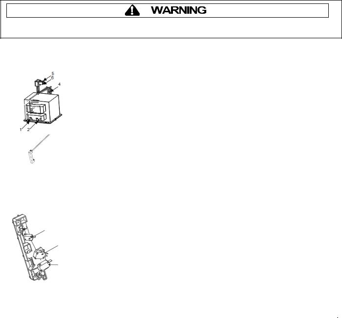
Transformer |
Discharge Capacitors |
|
|
|
|
Remove all wires from terminals. |
|
|
|
|
Measure resistance from: |
|
|
|
|
Terminal 1 to Terminal 2.................................. |
2.0 Ω. |
|
|
|
Wire 5 to Wire 6 ............................................... |
|
Less than 1 Ω. |
|
|
Terminal 4 to Ground screw on transformer... |
127Ω. |
|
|
|
Terminal 4 to any other terminal ...................... |
Infinite resistance |
|
|
HV Fuse |
Resistance |
|
Continuity |
|
|
Rated 700ma 5KV |
||
|
(Terminal 4) |
|
|
|
|
|
|
|
|
|
|
|
|
|
|
Interlock switch |
|
|
|
|
assembly |
|
|
|
|
|
With door open measure resistance from: |
|
|
|
|
Terminal C to NO |
Secondary...................... |
Infinite |
|
|
Terminal C to NC |
Monitor ........................... |
Continuity |
Secondary |
|
Terminal C to NO |
Primary / Logic............... |
Infinite |
Interlock |
|
|
|
|
Switch |
|
With door closed measure resistance from: |
Continuity |
|
|
|
|||
Monitor |
|
Terminal C to NO |
Secondary...................... |
Infinite |
Interlock |
|
Terminal C to NC |
Monitor ........................... |
Continuity |
Switch |
|
Terminal C to NO |
Primary / Logic |
|
|
|
|
||
Primary |
|
|
|
|
Interlock |
|
|
|
|
Switch |
|
|
|
|
|
|
|
|
|
Wire Harness |
|
Disconnect wires to switch. |
Continuity. |
|
Service Mode
To Check Magnetron Hours or Door Cycles:
1)Open door and Press/Hold Pad #3 for 5 seconds or until “SErV” is Displayed
2)Press Pad #1 to display Magnetron Hours in 100’s.
3)Press Pad #3 to display Door Cycles in 100’s
July 2019 |
3 |
©2019 ACP, Inc. |
16500066 |
 Loading...