


Commercial Microwave—Technical Information
120V, 60 Hz Models
RMS10TSA |
P2006701M |
RMS10DSA |
P2006702M |
MMS10TSA |
P2006705M |
MMS10DSA |
P2006706M |
Due to possibility of personal injury or property damage, always contact an authorized technician for servicing or repair of this unit.
Service should only be performed by a Qualified Service Technician
To avoid the risk of electrical shock, personal injury or death, disconnect power to oven and discharge capacitor before servicing.
Models |
*MS10DSA / *MS10TSA |
|
|
Power Source |
|
Voltage AC |
120 VAC |
|
|
Amperage (Single Unit) |
15 A |
Frequency |
60 Hz |
Single Phase, 3 wire grounded |
X |
|
|
Receptacle |
5-15R |
Plug |
5-15P |
|
|
Power Output |
|
Nominal microwave energy (IEC705) |
1000 Watts |
|
|
Minimum temperature rise (∆T) |
10º F / 5º C |
Operating Frequency |
2450 MHz |
|
|
Power Consumption |
|
Cook Condition Microwave |
1550 Watts |
|
|
Dimensions |
|
Cabinet |
|
Width |
512 (20 1/8”) |
|
|
Height |
310 (12 1/4”) |
Depth |
403 (15 7/8”) |
Oven Interior |
|
Width |
330 (13") |
Height |
197 (7 3/4") |
Depth |
330 (13") |
Weight |
|
|
|
Crated |
16.8kg (37 lbs) |
Uncrated |
13.6 kg. (30 lbs) |
|
|
May 2019
©2019 ACP, Inc. |
16500067 |
|
Rev 2 |

Component Testing Procedures
To avoid risk of electrical shock, personal injury or death, disconnect power to oven and discharge capacitor before servicing, unless testing requires power.
Illustration |
Component |
Test |
Results |
||||
|
|
|
|
|
Thermal Cutout |
Disconnect all wires from TCO. |
|
|
|
|
|
|
|
Measure resistance across terminals. |
|
|
|
|
|
|
|
|
|
|
|
|
|
|
|
|
|
|
|
|
|
|
|
Cavity TCO…………...................................... |
Open at 203° F (95° C) Closes at 185° |
|
|
|
|
|
|
|
F (85° C) |
|
|
|
|
|
|
Magnetron TCO.............................................. |
|
|
|
|
|
|
|
|
Open at 293° F (145° C) Closes at 275° |
|
|
|
|
|
|
|
F (135° C) |
|
|
|
|
|
Diode/Rectifier |
Discharge Capacitor |
Infinite resistance should be measured in |
|
|
|
|
|
|
|
one direction and 50KΩ or more in the |
|
|
|
|
|
|
Remove diode lead from capacitor and |
opposite direction. |
|
|
|
|
|
|
connect ohmmeter. |
NOTE: Test meter must contain a |
|
|
|
|
|
|
|
|
|
|
|
|
|
|
Reverse leads for second test. |
battery of 6 volts minimum. |
|
|
|
|
|
|
|
|
|
|
|
|
|
Capacitor |
Discharge Capacitor |
|
|
|
|
|
|
|
|
1.05uf |
|
|
|
|
|
|
Remove wires from capacitor terminals and |
Between Terminals: Meter should |
|
|
|
|
|
|
connect ohmmeter, set on highest |
|
|
|
|
|
|
|
momentarily deflect towards zero then |
|
|
|
|
|
|
|
resistance scale to terminals. |
|
|
|
|
|
|
|
return to over 5 MΩ. If no deflection |
|
|
|
|
|
|
|
|
|
|
|
|
|
|
|
|
occurs, or if continuous deflection |
|
|
|
|
|
|
|
occurs, replace capacitor. |
|
|
|
|
|
|
Also check between each terminal and |
Terminal to Case: Infinite resistance. |
|
|
|
|
|
|
capacitor case. |
|
|
|
|
|
|
|
|
|
|
|
|
|
|
Magnetron |
Discharge Capacitor |
2M248(J)A-B2 |
|
|
|
|
|
|
|
Between Terminals: Less than 1 Ω. |
|
|
|
|
|
|
Remove wires from magnetron and |
|
|
|
|
|
|
|
connect ohmmeter to terminals. Also check |
Each terminal to ground measures |
|
|
|
|
|
|
between each terminal and ground. |
Infinite resistance. |
|
|
|
|
|
|
NOTE: This test is not conclusive. If |
|
|
|
|
|
|
|
|
|
|
|
|
|
|
|
|
oven does not heat and all other |
|
|
|
|
|
|
|
components test good replace the |
|
|
|
|
|
|
|
magnetron and retest. |
|
|
|
|
|
|
|
|
|
|
|
|
|
Stirrer Motor |
Remove all wires from terminals. |
|
|
|
|
|
|
|
|
120vac 60hz 35RPM |
|
|
|
|
|
|
Measure resistance from: |
Bidirectional |
|
|
|
|
|
|
......................................terminal to terminal |
Approximately 4K Ω. |
|
|
|
|
|
|
|
|
|
|
|
|
|
Blower Motor |
Remove all wires from motor. |
|
|
|
|
|
|
|
Measure resistance from terminal to |
Approximately 45 Ω. |
|
|
|
|
|
|
terminal… ....................................................... |
|
|
|
|
|
|
|
|
|
|
|
|
|
|
Fuse Block |
Power In terminals....................................... |
120vac |
|
|
|
|
|
Filter Assembly |
Power Out terminals .................................... |
120vac |
|
|
|
|
|
|
|
If no power in, check power outlet If |
|
|
|
|
|
|
|
no power out, check fuse |
|
|
|
|
|
|
Fuse…………………………………………… |
Rated 20A Fuse 250vac |
|
|
|
|
|
|
|
|
|
|
|
|
|
|
|
|
May 2019
©2019 ACP, Inc. |
16500067 |
|
Rev 2 |
Component Testing Procedures
To avoid risk of electrical shock, personal injury or death, disconnect power to oven and discharge capacitor before servicing, unless testing requires power.
Illustration |
Component |
Test |
Results |
|
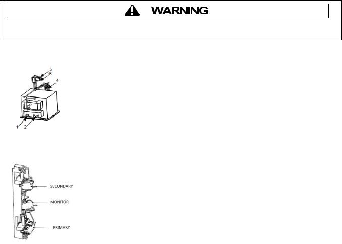
Transformer |
Discharge Capacitors |
|
|
|
Remove all wires from terminals. |
|
|
|
Measure resistance from: |
|
|
|
Terminal 1 to Terminal 2........................................... |
2.0 Ω. |
|
|
Wire 5 to Wire 6 ......................................................... |
<1.0 Ω. |
|
|
Terminal 4 to Ground screw on transformer.............. |
102Ω. |
|
|
Terminal 4 to any other terminal ............................... |
Infinite |
|
|
|
|
|
Interlock |
1) Inspect Latch for Cracking/Breakage |
|
|
Switch |
2) Disconnect Wires to Switch. |
|
|
Assembly |
|
|
|
|
With door open measure resistance: |
|
|
|
Secondary…………………………………. |
Infinite |
|
|
Monitor……………………………………... |
Continuity |
|
|
Primary…………………………………….. |
Infinite |
|
|
With door closed measure resistance: |
|
|
|
Secondary…………………………………. |
Continuity |
|
|
Monitor……………………………………... |
Infinite |
|
|
Primary…………………………………….. |
Continuity |
|
|
|
|
Service Mode
To Check Magnetron Hours or Door Cycles:
1)Open door and Press/Hold Pad #3 for 5 seconds or until “SErV” is Displayed
2)Press Pad #1 to display Magnetron Hours in 100’s.
3)Press Pad #3 to display Door Cycles in 100’s
May 2019
©2019 ACP, Inc. |
16500067 |
|
Rev 2 |
 Loading...