

Page 1
Accelerated Cooking Products
INC.
This document covers ARX* and MRX* series models
Service Manual
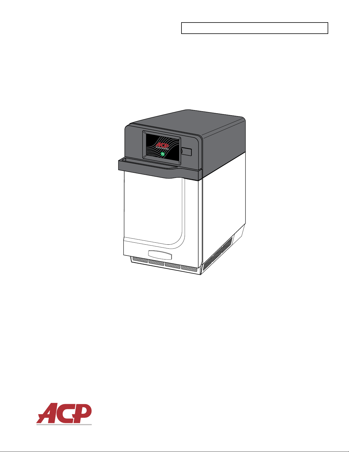
HIGH SPEED COMMERCIAL COMBINATION OVEN
Keep these instructions for future reference.
Please read this manual thoroughly before attempting to
install, operate or service this equipment.
Prior to servicing this equipment, please refer to the
SAFETY INSTRUCTIONS contained in this manual for
important safety information.
Models Covered: ARX1, ARX1BL, ARX2, ARX2BL
MRX1, MRX1BL, MRX2, MRX2BL
16400033
December 2018
Page 2

Table of Contents
Model Identication........................................................................................................................................................5
Online Oven Resources ................................................................................................................................................5
ACP Programming Application ................................................................................................................................... 5
Firmware Updates ...................................................................................................................................................... 5
Important Safety Instructions ......................................................................................................................................... 7
General Safety Instructions ........................................................................................................................................... 9
Theory of Operation.....................................................................................................................................................12
Sequence of Operation................................................................................................................................................12
Specications ..............................................................................................................................................................14
Grounding and Installation...........................................................................................................................................15
Grounding/Earthing Instructions ................................................................................................................................15
External Equipotential Earthing Terminal (export only) ............................................................................................15
Installation ...................................................................................................................................................................15
Unpack Oven ............................................................................................................................................................. 15
Place Oven on Counter .............................................................................................................................................15
Install Cook Plate ....................................................................................................................................................... 15
Oven Clearances .....................................................................................................................................................15
Touch Panel Menu Descriptions .................................................................................................................................. 17
Touch Screen Icon Descriptions .................................................................................................................................. 18
Basic Oven Operation .................................................................................................................................................19
Power On Oven, Preheat ........................................................................................................................................... 19
Power O Oven .........................................................................................................................................................19
Methods of Cooking and Programming .....................................................................................................................19
First Time Use ............................................................................................................................................................ 19
Set User Options ...................................................................................................................................................... 19
Preprogrammed Menu.................................................................................................................................................20
Cooking with Preprogrammed Menu Items................................................................................................................20
Manual Cooking...........................................................................................................................................................21
Manual Programming .................................................................................................................................................. 23
Save a Menu Item from Manual Cook: .....................................................................................................................23
Manually Edit an Existing Menu Item: ........................................................................................................................ 23
Manually Move Recipe:..............................................................................................................................................23
Manual Organization: Folders .....................................................................................................................................24
Manual Organization: Tabs .......................................................................................................................................... 25
Oven Programming: USB Flash Drive ......................................................................................................................... 26
Export Menu via USB Flash Drive .............................................................................................................................26
Open Menu in ACP Programming Application ...........................................................................................................26
Import Menu via USB Flash Drive..............................................................................................................................26
Oven Programming: Wi-Fi and Ethernet .....................................................................................................................27
Connect Oven to Network .......................................................................................................................................... 27
To connect via Wi-Fi ................................................................................................................................................. 27
To connect via Ethernet ............................................................................................................................................ 27
Connect Computer to Oven via Wi-Fi/Ethernet..........................................................................................................27
Transfer Recipe Information via Wi-Fi/Ethernet ......................................................................................................... 27
Log-in Information ....................................................................................................................................................27
Care and Cleaning.......................................................................................................................................................29
Recommended Cleaning Supplies .......................................................................................................................... 29
For a new oven, before using it for the rst time ...................................................................................................... 29
Daily Cleaning .......................................................................................................................................................... 30
Weekly Cleaning ......................................................................................................................................................30
User Options ...............................................................................................................................................................32
Access and Modify User Options .............................................................................................................................. 32
Default User Options .................................................................................................................................................. 33
Firmware Update Procedure .......................................................................................................................................35
Before Calling for Service ............................................................................................................................................ 38
Service Test Mode ...................................................................................................................................................... 39
With the PIN Code enabled .......................................................................................................................................39
Page 3

Table of Contents (continued)
With the PIN Code not enabled .................................................................................................................................39
Oven Tests ...................................................................................................................................................................42
Power Test .................................................................................................................................................................42
Set Up: .....................................................................................................................................................................42
Equipment ................................................................................................................................................................42
Procedure .................................................................................................................................................................42
Microwave Leak Test .................................................................................................................................................43
Measuring Procedure.................................................................................................................................................44
Error Codes .................................................................................................................................................................45
Troubleshooting Chart .................................................................................................................................................46
Panel Removal ............................................................................................................................................................48
Top Panel ...................................................................................................................................................................48
Side Panels ................................................................................................................................................................48
Rear Panel .................................................................................................................................................................48
Removal and Replacement ......................................................................................................................................49
Rear Exhaust Duct Removal .......................................................................................................................................49
Oven Thermal Cutout (TCO) .......................................................................................................................................50
Testing........................................................................................................................................................................50
Removal and Replacement........................................................................................................................................50
Triacs ...........................................................................................................................................................................51
Testing........................................................................................................................................................................51
Removal and Replacement........................................................................................................................................51
Autotransformer and Snubber .....................................................................................................................................52
Testing........................................................................................................................................................................52
Autotransformer .......................................................................................................................................................52
Snubber ....................................................................................................................................................................52
Removal and Replacement........................................................................................................................................52
Cooling Fan Relay (24V) .............................................................................................................................................53
Testing........................................................................................................................................................................53
Removal and Replacement .......................................................................................................................................53
Power Relay ................................................................................................................................................................54
Testing........................................................................................................................................................................54
Removal and Replacement........................................................................................................................................54
HV Capacitor ...............................................................................................................................................................55
Testing........................................................................................................................................................................55
Removal and Replacement........................................................................................................................................55
HV Diode .....................................................................................................................................................................56
Testing........................................................................................................................................................................56
Removal and Replacement........................................................................................................................................56
Magnetron TCO ...........................................................................................................................................................57
Testing........................................................................................................................................................................57
Removal and Replacement........................................................................................................................................57
Magnetron ...................................................................................................................................................................58
Testing........................................................................................................................................................................58
Removal and Replacement........................................................................................................................................58
Stirrer (Antenna) Motor ................................................................................................................................................59
Testing........................................................................................................................................................................59
Removal and Replacement........................................................................................................................................59
Wave Guide .................................................................................................................................................................60
Removal and Replacement........................................................................................................................................60
HV Transformer ...........................................................................................................................................................61
Testing........................................................................................................................................................................61
Removal and Replacement........................................................................................................................................61
Primary Interlock Switch ..............................................................................................................................................62
Testing........................................................................................................................................................................62
Removal and Replacement........................................................................................................................................62
Page 4

Table of Contents (continued)
Secondary, Monitor and Tertiary Interlock Switches ....................................................................................................63
Testing........................................................................................................................................................................63
Removal and Replacement........................................................................................................................................63
For Secondary and Monitor Switches ......................................................................................................................63
For Tertiary Switch ....................................................................................................................................................63
Power Supply Board ....................................................................................................................................................64
Testing........................................................................................................................................................................64
Removal and Replacement........................................................................................................................................64
Main Control Board......................................................................................................................................................65
Testing........................................................................................................................................................................65
Removal and Replacement........................................................................................................................................65
Touch Screen Display Board .......................................................................................................................................66
Testing........................................................................................................................................................................66
Removal and Replacement........................................................................................................................................66
Temperature Sensor ....................................................................................................................................................67
Testing........................................................................................................................................................................67
Removal and Replacement........................................................................................................................................67
Convection Motor ........................................................................................................................................................68
Testing........................................................................................................................................................................68
Removal and Replacement........................................................................................................................................68
Heater ..........................................................................................................................................................................69
Heater ........................................................................................................................................................................69
Testing........................................................................................................................................................................69
Removal and Replacement........................................................................................................................................69
Cooling Fans ...............................................................................................................................................................70
Testing........................................................................................................................................................................70
Removal and Replacement........................................................................................................................................70
Cooling Fan Motor Run Capacitors .............................................................................................................................71
Testing........................................................................................................................................................................71
Removal and Replacement........................................................................................................................................71
Wiring Diagrams & Schematics ...................................................................................................................................73
Electrical Schematic: Models Amx1, Amx1bl, Mrx1, Mrx1bl .....................................................................................73
Wiring Diagram: Models Amx2, Amx2bl, Mrx2, Mrx2bl ............................................................................................74
Electrical Schematic: Models Amx2, Amx2bl, Mrx2, Mrx2bl .....................................................................................75
Wiring Diagram: Models Amx2, Amx2bl, Mrx2, Mrx2bl ............................................................................................76
Page 5
Model Identication
When contacting ACP, provide product information.
Product information is located on oven serial plate.
Record the following information:
Model Number: _____________________________
Serial or S/N Number: ________________________
Date of installation: __________________________
Dealer’s name and address: ___________________
__________________________________________
__________________________________________
Before servicing this oven, please take the time to read the Safety Instructions contained in this manual.
Information herein is subject to change without notice. Errors are subject to correction.
For the most recent product literature, please visit acpsolutions.com/product-literature/
Any questions or to locate an authorized ACP servicer,
call ACP ComServ Service Support.
– Inside the U.S.A. or Canada, call toll-free at
866-426-2621.
– Outside the U.S.A. and Canada, call 319-368-8195.
– Email: commercialservice@acpsolutions.com
Warranty service must be performed by an authorized
ACP servicer. ACP also recommends contacting an
authorized ACP servicer, or ACP ComServ Service
Support if service is required after warranty expires.
Online Oven Resources
ACP Programming Application
Download and install the ACP Programming Application to create, edit, and customize menu
and display settings for your oven, using a desktop computer or tablet.
To download the latest and greatest version of the ACP Programming Application
please visit acpsolutions.com/oven-programming/
Firmware Updates
For the optimal user experience, ACP recommends using the latest version of oven rmware.
To download rmware updates and installation instructions, or to opt-in for email update
notications, please visit acpsolutions.com/oven-programming/
©2018 ACP, Inc.
Cedar Rapids, IA 52404 Page 5 of 80
Part No. 16400033
Original Instructions
Page 6

1
Important Safety Information
©2018 ACP, Inc.
Cedar Rapids, IA 52404 Page 6 of 80
Part No. 16400033
Original Instructions
Page 7
IMPORTANT SAFETY INSTRUCTIONS
RECOGNIZE THIS SYMBOL AS A SAFETY MESSAGE
⚠
WARNING
⚠
When operating this oven, you must follow safety precautions to reduce the risk of personal injury due to burns,
electric shock or possible exposure to microwave energy.
Important Notice for Servicers and Consumers
ACP will not be responsible for personal injury or property damage from improper service procedures. Pride
and workmanship go into every product to provide our customers with quality products. It is possible, however,
that during its lifetime a product may require service. Products should be serviced only by a qualied service
technician who is familiar with the safety procedures required in the repair of this equipment and who is
equipped with the proper tools, parts, testing instruments and the appropriate service information.
IT IS THE TECHNICIANS RESPONSIBLITY TO REVIEW ALL APPROPRIATE SERVICE INFORMATION
BEFORE BEGINNING REPAIRS.
WARNING
⚠
To avoid risk of severe personal injury or death, disconnect power before working/servicing on appliance to avoid
electrical shock.
Recognize Safety Symbols, Words, and Labels
Immediate hazards which WILL result in severe
DANGER
⚠
WARNING
⚠
CAUTION
⚠
E-Mail: commercialservice@acpsolutions.com
Telephone: 1-866-426-2621 or 319-368-8195
Amana® Commercial
ARX Contact:
ComServ Support Center
Web Site: www.acpsolutions.com
personal injury or death.
Hazards or unsafe practices which COULD result in
severe personal injury or death.
Hazards or unsafe practices which COULD result in
minor personal injury, product or property damage.
Menumaster® MRX
Contact:
©2018 ACP, Inc.
Cedar Rapids, IA 52404 Page 7 of 80
Part No. 16400033
Original Instructions
Page 8

IMPORTANT SAFETY INSTRUCTIONS
RECOGNIZE THIS SYMBOL AS A SAFETY MESSAGE
⚠
WARNING
⚠
Read the following information to avoid possible exposure to microwave radiation:
The basic design of the microwave oven makes it an inherently safe device to both use and service.
However, there are some precautions which should be followed when servicing the microwave to maintain this
safety. These are as follows:
1. ALWAYS operate the oven from an adequately
grounded outlet. Do not operate on a two-wire
extension cord.
2. Before servicing the oven (if oven is operable)
perform the microwave leakage test.
3. The oven should NEVER be operated if the door
does not properly seat against the seal; the hinges
or hinge bearings are damaged or broken; the
choke is damaged, (pieces missing, etc.); or any
other visible damage can be noted. Check the
choke area to ensure that this area is clean and
free of all foreign matter.
4. If the oven operates with the door open and
produces microwave energy, take the following
steps:
Tell the user not to operate the oven.
Contact ACP ComServ immediately.
5. ALWAYS have the oven disconnected when the
outer case is removed except when making the
“live” tests called for in the Service Manual. DO
NOT reach into the oven area while the oven is
energized. Make all connections for the test and
check them for tightness before plugging the cord
into the outlet.
6. ALWAYS ground the capacitors on the
magnetron lter box with an insulated-handle
screwdriver before working in the high voltage
area of the oven compartment. Some types of
failures will leave a charge in these capacitors and
the discharge could cause a reex action which
could make you injure yourself.
7. ALWAYS remember that in the area of the
transformer there is HIGH VOLTAGE. When the
oven is operating keep this area clear and free
of anything which could possibly cause an arc or
ground, etc.
8. DO NOT for any reason defeat the interlock
switches. There is no valid reason for this action
at any time; nor will it be condoned by ACP.
9. IMPORTANT: Before returning an oven to a
customer, be sure to check for proper switch
interlock action.
10. The microwave oven should never be operated
with any components removed and/or bypassed
or when any of the safety interlocks are found to
be defective, or when any of the seal surfaces are
defective, missing, or damaged.
11. All microwave ovens meet all requirements of
the radiation control for Health and Safety Act
of 1968. Due to measurement uncertainties, the
maximum leakage for the eld will be 4mW/cm2.
12. To ensure that the oven does not emit excessive
microwave leakage and to meet the Department
of Health and Human Services guidelines,
check the oven for microwave leakage using a
microwave oven leakage meter that complies
with US Government CDRH / FDA / DHHS
requirements and or any other local government
requirements. The maximum leakage level
allowed by ACP is 4mW/cm2.
13. If servicer encounters an emission reading
over 4mW/cm2, the servicer is to cease repair
and contact the ACP ComServ Department
immediately for further direction. ACP will contact
the proper Government Agency upon verication
of the test results.
©2018 ACP, Inc.
Cedar Rapids, IA 52404 Page 8 of 80
SAVE THESE INSTRUCTIONS
Part No. 16400033
Original Instructions
Page 9

GENERAL SAFETY INSTRUCTIONS
RECOGNIZE THIS SYMBOL AS A SAFETY MESSAGE
⚠
WARNING
⚠
When using electrical equipment, basic safety precautions should be followed to reduce the risk of burns,
electrical shock, re, or injury to persons including the following:
1. READ all instructions before using oven.
2. READ AND FOLLOW the specic “PRECAUTIONS
TO AVOID POSSIBLE EXPOSURE TO EXCESSIVE
MICROWAVE ENERGY”.
3. This oven MUST BE GROUNDED. Connect only to
properly GROUNDED outlet. See “ GROUNDING /
EARTHING INSTRUCTIONS”.
4. Install or locate this oven ONLY in accordance with the
installation instructions in this manual.
5. Liquids or other foods, MUST NOT BE HEATED in
sealed containers since they are likely to explode.
6. Eggs in their shell and whole hard-boiled eggs
SHOULD NOT BE HEATED in microwave ovens
since they may explode even after microwave heating
has ended.
7. Use this oven ONLY for its intended use as described
in this manual. DO NOT use corrosive chemicals or
vapors in this oven. This type of oven is specically
designed to heat, cook, or dry food. It is not designed for
industrial or laboratory use.
8. This oven is NOT intended for use by persons
(including children) with reduced physical, sensory
or mental capabilities, or lack of experience and
knowledge, unless they have been given supervision or
instruction concerning use of the appliance by a person
responsible for their safety.
9. CHILDREN SHOULD BE SUPERVISED to ensure
that they DO NOT play with the appliance.
10. Failure to maintain the oven in a clean condition could
lead to deterioration of the surface that could adversely
aect the life of the appliance and possibly result in a
hazardous situation.
11. DO NOT heat baby bottles in oven. Baby food jars
must be open when heated and contents stirred or
shaken before consumption in order to avoid burns.
12. DO NOT operate this oven if it has a damaged cord
or plug, if it is not working properly, or if it has been
damaged or dropped.
13. This oven, including power cord, must be serviced
ONLY by qualied service personnel. Special tools are
required to service oven. Contact nearest authorized
service facility for examination, repair, or adjustment.
14. DO NOT cover or block louvers or other openings on
oven.
15. DO NOT store this oven outdoors. DO NOT use
this product near water – for example, near a kitchen
sink, in a wet basement, a swimming pool, or a similar
location.
16. DO NOT immerse cord or plug in water.
17. Keep cord A W AY from HEATED surfaces.
18. DO NOT let cord hang over edge of table or counter.
19. For commercial use only.
PRECAUTIONS TO AVOID POSSIBLE EXPOSURE TO
EXCESSIVE MICROWAVE ENERGY
A. DO NOT attempt to operate this oven with the door open since open door operation can result in harmful exposure to
microwave energy. It is important not to defeat or tamper with the safety interlocks.
B. DO NOT place any object between the oven front face and the door to allow soil or cleaner residue to accumulate on
sealing surfaces.
C. DO NOT operate the oven if it is damaged. It is particularly important that the oven door close properly and that there is
no damage to the:
1. door (bent)
2. hinges and latches (broken or loosened)
3. door seals and sealing surfaces.
D. The oven should not be adjusted or repaired by anyone except properly qualied service personnel.
©2018 ACP, Inc.
Cedar Rapids, IA 52404 Page 9 of 80
SAVE THESE INSTRUCTIONS
Part No. 16400033
Original Instructions
Page 10
GENERAL SAFETY INSTRUCTIONS
RECOGNIZE THIS SYMBOL AS A SAFETY MESSAGE
⚠
To avoid risk of re in the oven cavity:
a. DO NOT overcook food. Carefully attend oven
when paper, plastic, or other combustible materials
are placed inside the oven, due to the possibility of
ignition.
b. Remove wire twist-ties from paper or plastic bags
before placing bag in oven.
c. If materials inside the oven ignite, keep oven door
CLOSED, turn oven o and disconnect the power
cord, or shut o power at the fuse or circuit breaker
panel.
d. DO NOT use the cavity for storage. DO NOT leave
paper products, cooking utensils, or food in the cavity
when not in use.
To avoid personal injury or property damage, observe the following:
WARNING
⚠
Liquids such as water, coee, or tea are able to be
overheated beyond the boiling point without appearing
to be boiling due to surface tension of the liquid. Visible
bubbling or boiling when the container is removed
from the microwave oven is not always present. THIS
COULD RESULT IN VERY HOT LIQUIDS SUDDENLY
BOILING OVER WHEN A SPOON OR OTHER
UTENSIL IS INSERTED INTO THE LIQUID.
To reduce the risk of injury to persons:
a. DO NOT overheat liquid.
b. Stir liquid both before and halfway through heating.
c. DO NOT use straight-sided containers with narrow necks.
d. After heating, allow container to stand in the microwave
oven for a short time before removing container.
e. Use extreme care when inserting a spoon or other
utensil into the container.
CAUTION
⚠
WARNING
⚠
1. DO NOT deep fat fry in oven. Fat could overheat
and be hazardous to handle.
2. DO NOT cook or reheat eggs in shell or with an
unbroken yolk using microwave energy. Pressure
may build up and erupt. Pierce yolk with fork or knife
before cooking.
3. Pierce skin of potatoes, tomatoes, and similar foods
before cooking with microwave energy. When skin is
pierced, steam escapes evenly.
4. DO NOT operate oven without load or food in oven
cavity.
5. Microwave popcorn should NOT be popped in oven.
6. DO NOT use regular cooking thermometers in oven.
Most cooking thermometers contain mercury and
may cause an electrical arc, malfunction, or damage
to oven.
7. DO NOT use metal utensils in oven.
8. DO NOT use aluminum foil in oven
9. NEVER use paper, plastic, or other combustible
materials that are not intended for cooking.
10. When cooking with paper, plastic, or other
combustible materials, follow manufacturer’s
recommendations on product use.
11. DO NOT use paper towels which contain nylon or
other synthetic bers. Heated synthetics could melt
and cause paper to ignite.
12. Do not heat sealed containers or plastic bags in
oven. Food or liquid could expand quickly and cause
container or bag to break. Pierce or open container
or bag before heating.
13. To avoid pacemaker malfunction, consult physician
or pacemaker manufacturer about eects of
microwave energy on pacemaker.
14. An authorized servicer MUST inspect oven annually.
Record all inspections and repairs for future use.
©2018 ACP, Inc.
Cedar Rapids, IA 52404 Page 10 of 80
SAVE THESE INSTRUCTIONS
Part No. 16400033
Original Instructions
Page 11

Introduction
2
Theory of Operation
Sequence of Operation
©2018 ACP, Inc.
Cedar Rapids, IA 52404 Page 11 of 80
Part No. 16400033
Original Instructions
Page 12

Theory of Operation
Utilizing technology that combines Convection and Hot Air-Impingement along with Microwaves, the ARX-MRX
family of High Speed Combination Ovens rapidly cook food without sacricing quality in a small footprint. The
controls allow either programmed or manual cooking to coordinate air velocity and microwave production as needed
to meet the cooking requirements of the specic product. The on-board catalytic converter allows for ventless
installation.
Sequence of Operation
The oven is turned “ON” and allowed to come up to the programmed cooking temperature.
With a Menu Item loaded into the oven cavity and the door closed, the operator can either select from a list of
preprogrammed menus or input manual cooking instructions.
There are cooking stages that can have dierent levels of microwave energy and impingement air velocity.
Once initiated, the oven’s Controller will signal the Magnetron circuit to operate from 0 to 100% by modulating the
circuit on and o (or on 100%) based on the program. Simultaneously, the Controller will regulate the Convection
Blower’s speed from 0 to 100% based on the program. At the end of each cooking stage, the oven can change to a
dierent microwave level and/or blower speed.
During these cooking stages, the oven controls the cooking temperature by energizing and de-energizing a heating
element.
©2018 ACP, Inc.
Cedar Rapids, IA 52404 Page 12 of 80
Part No. 16400033
Original Instructions
Page 13

Specications
3
Power Specication
· Input
· Output
· Consumption
Oven Dimensions
Weight
Grounding
Installation
©2018 ACP, Inc.
Cedar Rapids, IA 52404 Page 13 of 80
Part No. 16400033
Original Instructions
Page 14
Specications
MODELS ARX/MRX 2 ARX/MRX 1
Power Supply
Voltage AC 208-240 VAC 240 VAC
Amperage 30 A 20 A
Frequency 60 Hz 60 Hz
Single Phase
Plug NEMA 6-30P NEMA 6-20P
Power Output
Microwave 2000 W 1000 W
Convection 3000 W 3000 W
Frequency 2450 MHz 2450 MHz
Power Consumption
Watts 5950 W 3600 W
Amps @ 240V 28.6 A 18.2 A
Dimensions
Cabinet
Width 14 ⅛” (358mm) 14 ⅛” (358mm)
4 4
Height 22 ¾” (578mm) 22 ¾” (578mm)
Depth 29 ¼” (743mm) 29 ¼” (743mm)
Cavity
Width 12 ¼“ (312mm) 12 ¼“ (312mm)
Height 7” (178mm) 7” (178mm)
Depth 12 ¼“ (312mm) 12 ¼“ (312mm)
Weight
Crated 152 lbs. (69 kg) 134 lbs. (61 kg)
Uncrated 134 lbs. (61 kg) 116 lbs. (53 kg)
©2018 ACP, Inc.
Cedar Rapids, IA 52404 Page 14 of 80
Part No. 16400033
Original Instructions
Page 15
Grounding and Installation
Grounding/Earthing Instructions
WARNING
Oven MUST be grounded. Grounding reduces risk of electric shock
by providing an escape wire for the electric current if an electrical short
occurs. This oven is equipped with a cord having a grounding wire
with a grounding plug. The plug must be plugged into an outlet that is
properly installed and grounded.
Consult a qualied electrician or servicer if grounding instructions are not completely understood, or if doubt exists as to whether
the oven is properly grounded.
Do not use an extension cord.
If the product power cord is too short, have a qualied electrician install a three-slot receptacle. This oven should be plugged into
a separate circuit with the electrical rating as provided in the product specications. When the combination oven is on a circuit
with other equipment, an increase in cooking times may be required and fuses can be blown.
External Equipotential Earthing Terminal (export only)
The oven has a secondary earthing terminal. The terminal provides an external earthing connection used in addition to
the earthing prong on plug. Located on outside of oven back, the terminal is marked with symbol shown at right.
To avoid risk of electrical shock or
death, this oven must be grounded
Installation
STEP 1 - Unpack Oven
• Inspect oven for damage, such as
dents in door or inside oven cavity.
• Report any dents or breakage to
source of purchase immediately.
Do not attempt to use oven if
damaged.
• Remove all packing materials from
oven interior.
• If oven has been stored in an
extremely cold area, wait a few hours
before connecting power.
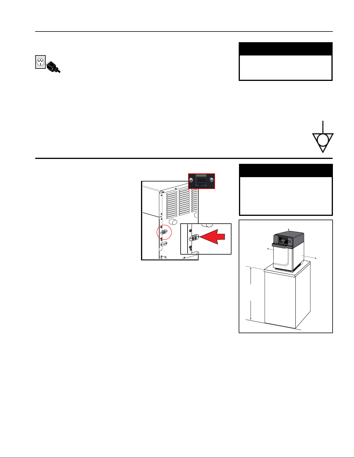
• If you plan to program via Ethernet, remove plastic plug from port on the right
rear of oven. Gently use pliers if necessary.
Use two or more people to move and
Failure to do so can result in back or
⚠
and plug must not be altered.
WARNING
⚠
Excessive Weight Hazard
install oven.
other injury
MIN. 2" (5.1 cm)
MIN.
1/2"
(1.27 cm)
(1.27 cm)
MIN.
1/2"
STEP 2 - Place Oven on Counter
• Recommended countertop surface depth is 28” (71 cm).
• Do not install oven next to or above source of heat, such as pizza oven
or deep fat fryer. This could cause oven to operate improperly and could shorten
life of electrical parts.
• Do not block or obstruct oven lters. Allow access for cleaning.
• Install oven on level countertop surface.
• Outlet should be located so that plug is accessible when oven is in place.
STEP 3 - Install Cook Plate
• Install oven cook plate
1. Oven cavity must be cool to touch.
2. Place cook plate in oven with curved edge toward the front of cavity.
CAUTION: DO NOT cook food directly on oor of oven.
⚠
©2018 ACP, Inc.
Cedar Rapids, IA 52404 Page 15 of 80
MIN.
36"
(91.5 cm)
Oven Clearances
A. Allow at least 2” (5.1 cm) of
clearance around top of oven.
Proper air ow around oven
cools electrical components. With
restricted air ow, oven may not
operate properly and life of electrical
parts is reduced.
B. There is not an installation
clearance requirement for the back
of the oven.
C. Allow at least 1/2” (1.27 cm) of
clearance around sides of oven.
D. Install oven so oven bottom is at
least 3 feet (91.5 cm) above oor.
Part No. 16400033
Original Instructions
Page 16

Oven Operation
4
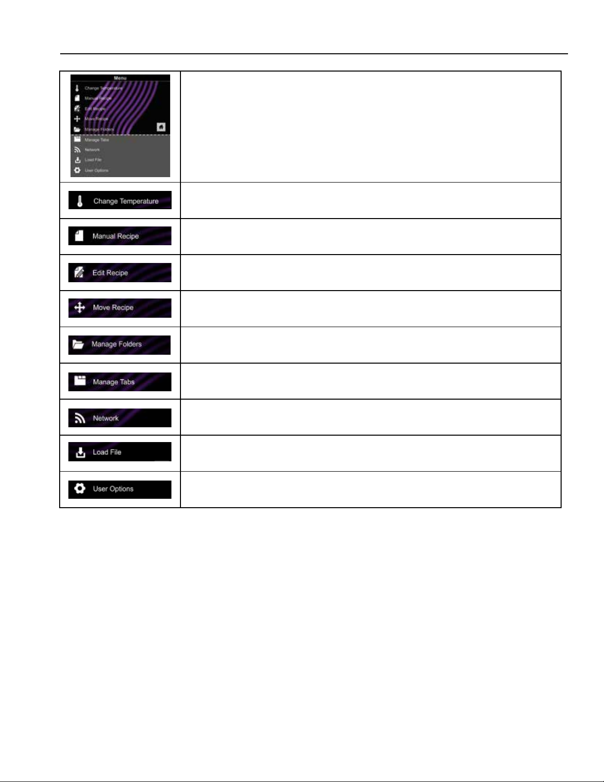
Touch Panel Menu Descriptions
Touch Screen Icon Descriptions
Basic Oven Operation
Preprogrammed Menu
Manual Cooking
©2018 ACP, Inc.
Cedar Rapids, IA 52404 Page 16 of 80
Part No. 16400033
Original Instructions
Page 17
Touch Panel Menu Descriptions
MENU SCREEN
• Scroll up or down to choose from dierent categories
CHANGE TEMPERATURE
• Changes current oven temperature
MANUAL RECIPE
• Manually enter settings for a recipe
EDIT RECIPE
• Change current oven temperature
MOVE RECIPE
• Move/reorganize individual programmed recipes
MANAGE FOLDERS
• Add or edit recipe folders
MANAGE TABS
• Add or edit recipe tabs
NETWORK
• Connect the oven to Wi-Fi
LOAD FILE
• Transfer a Menu le to the oven via USB Flash Drive
USER OPTIONS
• Modify a variety of user options such as key beep, temperature, etc.
©2018 ACP, Inc.
Cedar Rapids, IA 52404 Page 17 of 80
Part No. 16400033
Original Instructions
Page 18

Touch Screen Icon Descriptions
Breakfast Casse...
Breakfast Sand...
Omelet
Tuna Melt
POWER ON ICON
• Press to preheat oven.(Fan will continue to run if temperature is over 200°F / 95°C).
MENU ICON
• Press to access a Menu Screen for manually editing recipes, changing user options, etc.
HOME ICON
• Press to return to the Home Screen.
TIME ENTRY
• Indicates the Time entry column in Manual Cooking entry.
MICROWAVE POWER ENTRY
• Indicates the Microwave Power entry column in Manual Cooking entry.
FAN POWER ENTRY
• Indicates the Fan Power entry column in Manual Cooking entry.
SAVE ICON
• Press to Save a manually programmed recipe and return to the Main Screen.
GREEN CHECK MARK ICON
• Press to begin cooking after manually entering a recipe. Press to Save changes.
BACK ICON
• Press to return to previous Screen.
NEXT ICON
• Press to move to next Screen.
DELETE ICON
• Press to delete Menu Item, Folder, or Network.
•
PAUSE ICON
• Press to pause a Cook Cycle.
STOP ICON
• Press to cancel a Cook Cycle. Press to Stop and Return to the Main Screen.
NEW FOLDER ICON
• Press to add new Folder.
FOLDER ICONS
• Used to organize programmed recipes. Can be customized with color, icon, or image
Example: Pizza Folder - cheese pizza, pepperoni pizza, etc.
TAB ICONS
• Used to organize programmed recipes. Example: AM or PM Menus.
PROGRAMMED RECIPE ICON
• Press to begin the Cook Cycle for the desired recipe.
©2018 ACP, Inc.
Cedar Rapids, IA 52404 Page 18 of 80
Part No. 16400033
Original Instructions
Page 19
Basic Oven Operation
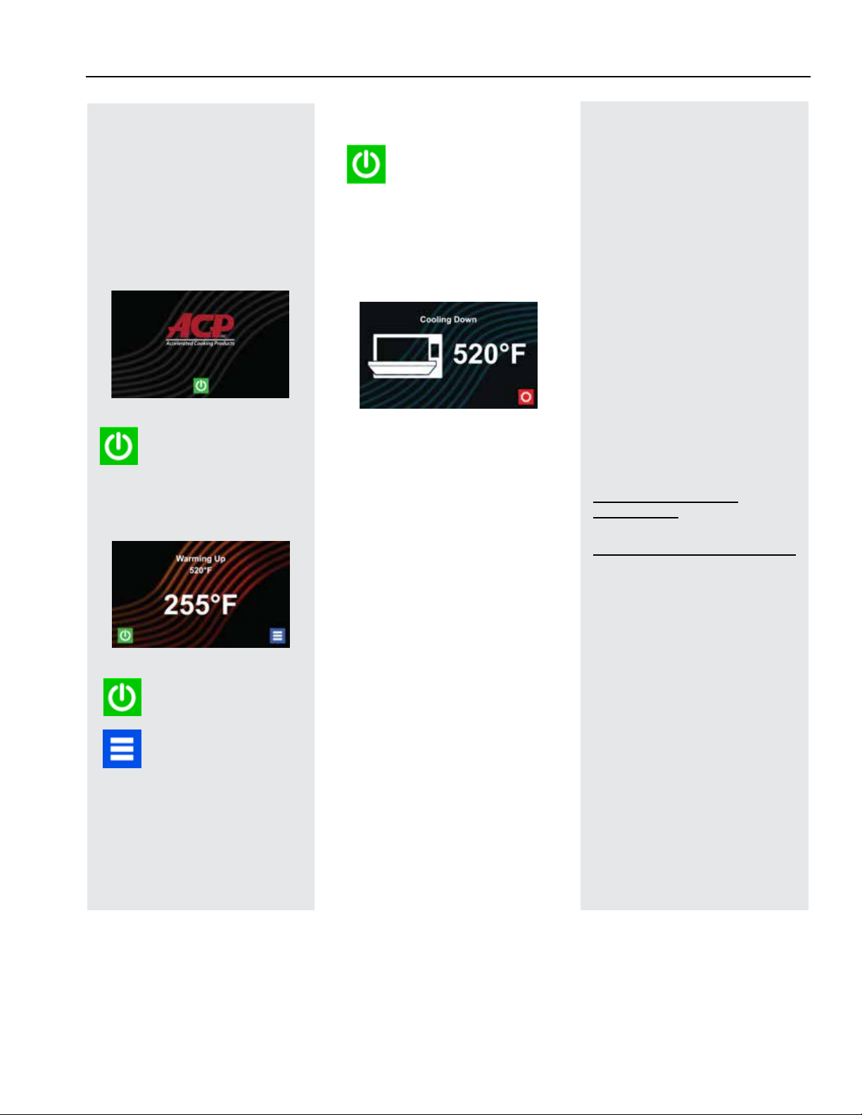
Power On Oven,
Preheat
This oven can be set to a
preheat temperature between
200°F (95°C) and 520°F (270°C).
Oven must be plugged in.
(Screen will power on to “Standby
Mode” within approximately 30 seconds.)
Press Green
Power Icon
Preheat temperature of oven
will appear in display.
Press the Power Icon
again to interrupt
preheating, or press the
Blue Menu Icon to
access Main Menu and
User Options.
Power Off Oven
At the end of the day,
turn the oven o by
pressing the Green
Power Icon on the screen. The
oven will begin cooling down.
The Oven Fan will continue to
run to cool the oven.
Cooling Down Screen appears
and stays on until oven
temperature is below 200°F
(95°C)
Caution: To avoid
⚠
damage to the convection
motor DO NOT turn o power
by unplugging the oven or
shutting o the power breaker
until the fan stops.
Methods of Cooking
and Programming
• Cooking with Preprogrammed
Menu Items
• Manual Cooking and Oven
Programming
• Recipe and Menu creation via
ACP Programming Application
• USB Programing
• Wi-Fi Programming
• Ethernet Programming
You may add and organize
recipe information by creating
new recipes, folders and
tabs. See Section – Manual
Programming.
To download and view example
menus, please visit
acpsolutions.com/ovenprogramming/
First Time Use
Set User Options
There are several options you
can change to customize the
operation of the oven for your
business. To access and edit
user options, see Section –
User Manual.
Set Time and Date settings
for current local time. This
oven maintains a data log
which is used to diagnose and
troubleshoot errors. An accurate
date and time are important for
the data log.
©2018 ACP, Inc.
Cedar Rapids, IA 52404 Page 19 of 80
Part No. 16400033
Original Instructions
Page 20

Preprogrammed Menu Items
The Home Screen on the oven displays Recipe Options. Scroll up and down with your nger to navigate
through On-Screen Menus and Recipes. After the oven has preheated, the Menu appears. The high-speed
oven comes preprogrammed with several Menu Items to simplify cooking.
Standard Preprogrammed Menu Items:
1. Breakfast Casserole
2. Breakfast Sandwich
3. Omelet
4. Tuna Melt
5. Crab Cakes
6. Pizza
7. Reuben Panini
8. Muuletta Panini
9. Fish Tacos
10. Salmon
11. Roasted Vegetables
12. Baked Potato
13. Ice Cream Sandwich
14. Grilled Pineapple
15. Chicken Wings
16. Fries
17. Shrimp
Cooking with Preprogrammed Menu Items
1. After oven has preheated to desired temperature, open oven door, place
food in oven and close door.
2. Scroll to choose desired food item from Menu and press the Food
Item you wish to cook. The Cook Cycle will begin and screen will show
remaining Cook Time.
Note: If “Preheat Warning” is enabled and preheat temperature diers
from default preheat temperature, the control will interrupt cook cycle to
guarantee that oven reaches desired temperature before cook cycle begins.
Enable “Preheat Warning” in user options.
3. At the end of the cooking cycle, the oven beeps and displays animation.
Use oven mitts and/or paddle to carefully remove food from oven.
1
2
3
©2018 ACP, Inc.
Cedar Rapids, IA 52404 Page 20 of 80
Part No. 16400033
Original Instructions
Page 21
Manual Cooking
Note: “Manual cooking” must be enabled in user options (see Section – User Options)
Use manual cooking when a specic entered time and cooking power levels are desired. Manual cooking is very
useful when you are experimenting with new food items. Maximum Cook Time is 99:99 (100 minutes and 13
seconds). Microwave and Fan can be set to power levels between 0-100%.
Note: You may also create and edit recipes using the ACP Programming Application.
1. After oven has preheated press Blue Menu Icon.
Note: To guarantee that oven reaches the desired temperature
before the start of cook cycle, enable “Preheat Warning” in user
options.
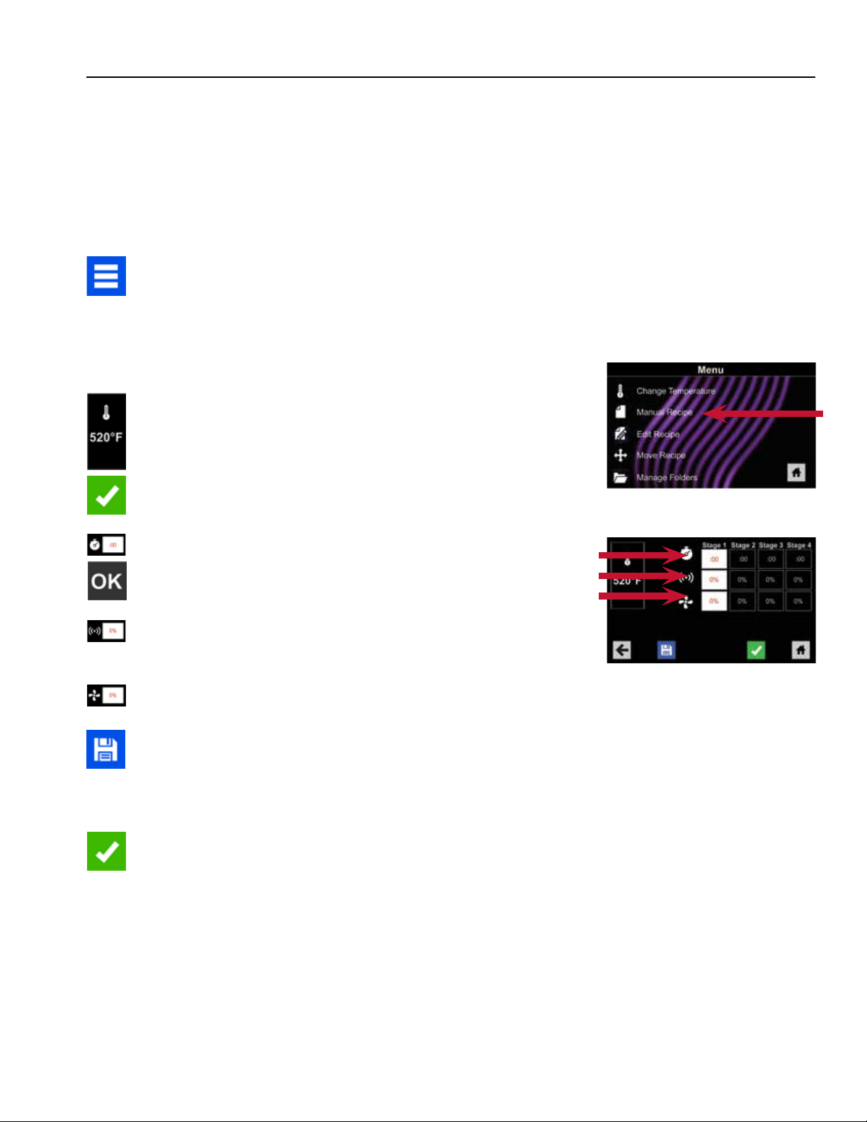
2. Press the “Manual Recipe” option.
3. To change cooking temperature for recipe, press Temperature
Icon on the left, and input new temperature. Two frequently used
temperatures will appear for quick selection.
Press Green Check Mark Icon after inputting a temperature.
4. For Stage 1, enter cooking time by pressing Time Entry Box.
A number pad will appear. Enter the desired Cook Time.
Press the “OK” Icon.
5. Select desired microwave power by pressing Microwave Power
Entry Box. Choose from options ranging from 0% - 100%.
6. Select desired fan speed by pressing Fan Speed Entry Box.
Choose from options ranging from 0% - 100%.
7. Repeat steps 4-6 for each cooking stage, if more than one
cooking stage is necessary.
Note: To Save without cooking rst, press the Save Icon.
Follow instructions on the next page.
2
4-6
Time
MW
Fan
8. Open oven door and place food in oven. Press the Green
Check Mark Icon to begin cooking. Once the cook cycle is
complete, open door and use oven mitts and/or paddle to
carefully remove food. The display will return to the Manual
Input Screen. See instructions on next page to Save and Edit
Menu Item from Manual Cook.
©2018 ACP, Inc.
Cedar Rapids, IA 52404 Page 21 of 80
Part No. 16400033
Original Instructions
Page 22

Programming
5
Manual Programming
Manual Organization: Folders
Manual Organization: Tabs
Oven Programming: USB Flash Drive
Oven Programming: Wi-Fi and Ethernet
©2018 ACP, Inc.
Cedar Rapids, IA 52404 Page 22 of 80
Part No. 16400033
Original Instructions
Page 23
Manual Programming
Save a Menu Item from Manual Cook:
1. To Save the settings and create Menu Item, press the Blue Save Icon.
2. Choose a background color and icon, or an image, to customize the
Menu Item.
3. Press the Right Arrow Icon to move to the next screen.
4. Name recipe and press the Green Check Mark Icon to Save.
5. To reorganize Menu Items, you may press, hold and drag them.
6. Press the Green Check Mark Icon to complete this step and Save the
Menu Item.
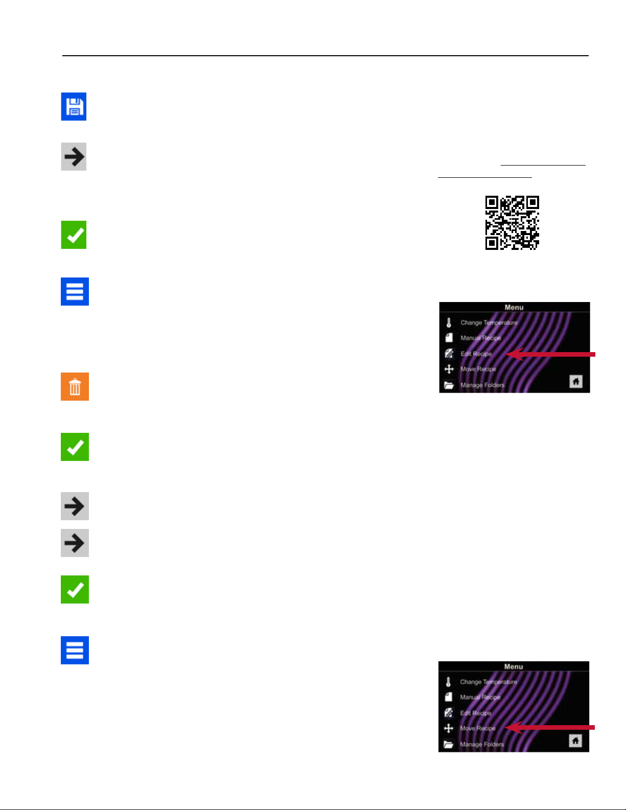
Manually Edit an Existing Menu Item:
1. Press the Blue Menu Icon at the bottom of the screen.
2. Press the “Edit Recipe” option.
3. Press the desired recipe to be edited. The control will prompt you
to the Manual Editing Screen where you may revise the Cooking
Settings.
Note: For larger and more
complex menus, it may be
more manageable to create
and edit menus using the
ACP Programming Application.
For detailed instructions,
please visit: acpsolutions.com/
oven-programming/
2
4. To delete the Menu Item, press the Orange Garbage Can Icon. Press
the Green Check Mark Icon to conrm, or press the “X” to dismiss.
Note: Skip the following step if you do not want to cook anything.
5. Open the oven door and place the food in the oven. Press the
Green Check Mark Icon to begin cooking with the revised Menu
Item settings. The display will return to the Manual Input Screen at
the end of the Cook Cycle.
6. Press the Right Arrow Icon to Save any changes made to Cook
Settings and move to the next screen.
7. If desired, choose a dierent background color. Press the Right
Arrow Icon to select an image at the next screen. Press the Right
Arrow Icon again to move to the next screen.
8. If desired, change the name of the recipe. Press the Green
Check Mark Icon to Save the Menu Item.
Manually Move Recipe:
1. Press the Blue Menu Icon at the bottom of the screen.
2. Press the “Move Recipe” option.
2
3. Press, hold, and drag recipes to dierent locations on the screen.
4. To move a recipe into a folder, press, hold and drag the recipe to
the folder.
5. To move a recipe out of a folder, press, hold and drag the recipe
to the top of the screen.
©2018 ACP, Inc.
Cedar Rapids, IA 52404 Page 23 of 80
Part No. 16400033
Original Instructions
Page 24
Manual Organization: Folders
Manually Create a Recipe Folder:
Note: You may also create folders using the ACP Programming Application.
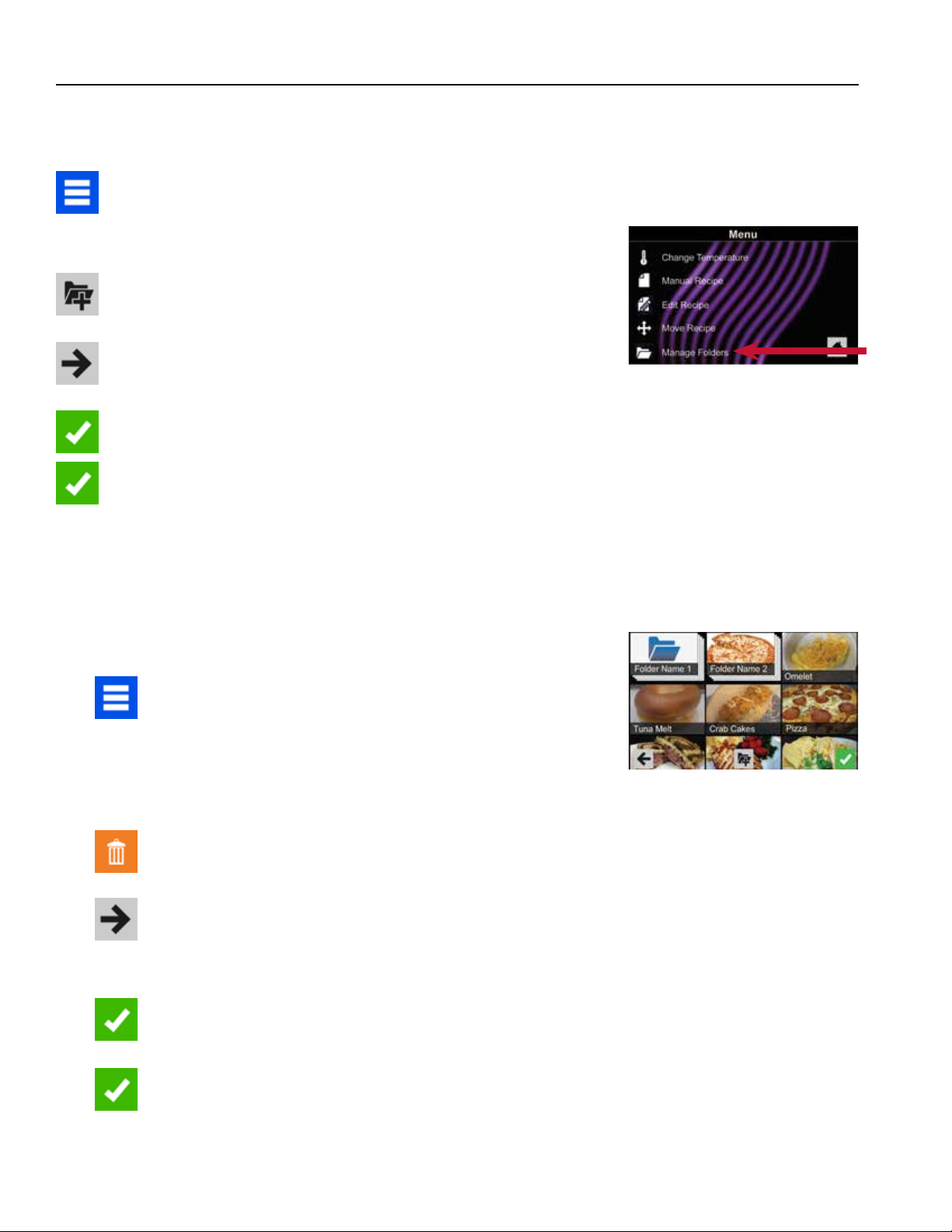
1. Press the Blue Menu Icon at the bottom of the screen.
2. Press the “Manage Folders” option in the Menu Screen.
3. To create a new folder, press the Grey Folder Icon at the bottom
of screen.
4. Choose a background color and icon, or an image, to customize
the folder. Conrm that your new folder appears on the Main
Screen. Press the Right Arrow Icon.
5. Name folder and press the Green Check Mark Icon to Save.
6. Conrm that your new folder appears on the Main Screen.
Press the Green Check Mark Icon again to Save the new folder.
Manually Edit an Existing Recipe Folder:
Note: You may also edit folders using the ACP Programming Application.
2
1. Press the Blue Menu Icon at the bottom of the screen.
2. Press the “Manage Folders” option in the Menu Screen.
3. Press the desired folder to be edited.
4. To delete the Folder: Press the Orange Garbage Can Icon.
Press the Check Mark Icon to conrm deletion. Or, press the “X” to
dismiss.
5. If desired, select a dierent photo, icon, or color for the folder.
Press the Right Arrow Icon to move to the next screen.
6. If desired, change the name of the recipe.
7. Press the Green Check Mark Icon to Save changes.
8. Press the Green Check Mark Icon once more to Save the revised
folder.
©2018 ACP, Inc.
Cedar Rapids, IA 52404 Page 24 of 80
Part No. 16400033
Original Instructions
Page 25

Manual Organization: Tabs
Manually Create a Recipe Tab
Note: You may also add recipe tabs using the ACP Programming Application.
1. Press the Blue Menu Icon at the bottom of the screen.
2. Press the “Manage Tabs” option in the Menu Screen.
3. Press the “Add Tab” option.
4. A new tab will appear at the top of the screen.
5. Press the Home Icon to return to the Main Screen.
Manually Edit an Existing Recipe Tab
Note: You may also edit tabs using the ACP Programming Application.
1. Press the Blue Menu Icon at the bottom of the screen.
2
2. Press the “Manage Tabs” option in the Menu Screen.
3. Press the desired tab to be edited.
Change the image on the tab: Press the “Choose Icon” option.
Select an image. Press the Green Check Mark Icon.
Add text to the tab: Press the “Enter Text on Tab” option. Enter
the desired text. Press the Green Check Mark Icon to Save.
Relocate the tab: Press the “Move Tab Right” or “Move Tab
Left” option.
Delete the tab: Press the “Delete Tab” option.
4. After changes have been made, press the Home Icon to Save
and return to the Main Screen.
2
3
©2018 ACP, Inc.
Cedar Rapids, IA 52404 Page 25 of 80
Part No. 16400033
Original Instructions
Page 26

Oven Programming: USB Flash Drive
Caution: Uploading a new le will overwrite existing items on oven. To
ensure items are not lost, rst backup les by exporting to USB drive.
Export Menu via USB Flash Drive
1. Press the Blue Menu Icon at the bottom of the screen.
2. Scroll down and press the “Load File” option.
3. When prompted, insert the Flash Drive into the USB port.
4. When prompted, select “Export Files”. “Copying Files” Screen
will appear. DO NOT remove USB Flash Drive until “Success”
Screen appears.
5. Once the les have copied, press the Home Icon to return to
the Main Screen. Remove USB Flash Drive. Settings and Menu
Items will be loaded on USB Flash Drive and ready to share or
open in ACP Programming Application.
2
3
4
Open Menu in ACP Programming Application
Note: For more comprehensive instructions, see ACP Programming
Application User Guide online.
1. Insert Flash Drive into USB port on computer.
2. Open ACP Programming Application.
3. Select “File,” then “Open.” Navigate to Flash Drive.
4. Select the Menu le and Open.
Import Menu via USB Flash Drive
1. Press the Blue Menu Icon at the bottom of the screen.
2. Scroll down and press the “Load File” option.
Caution: Uploading a new le will overwrite existing items on oven.To
ensure items are not lost, rst backup les by exporting to USB drive.
3. When prompted, insert the Flash Drive into the USB port.
4. Press the desired le to be uploaded.
5. Once le has uploaded, press the Home Icon to return to the
Main Screen. Settings and Menu Items will now be loaded and
ready to use.
4
©2018 ACP, Inc.
Cedar Rapids, IA 52404 Page 26 of 80
Part No. 16400033
Original Instructions
Page 27

Oven Programming: Wi-Fi and Ethernet
Connect Oven to Network:
1. Press the Blue Menu Icon at the bottom of the screen.
2. Press the “Network” option.
3. Connect to network using your choice of Ethernet or Wi-Fi:
To connect via Wi-Fi
• Enable Wi-Fi capability by pressing the “ON” option.
• Select the desired Wi-Fi network. Enter the network’s
password. If the network does not immediately appear,
press “Search” to locate the Wi-Fi network.
To connect via Ethernet:
• Make sure the Ethernet cord is plugged into the back of
the oven and wall jack. If necessary, use pliers to gently
remove plastic plug from Ethernet port on right rear of
oven.
• Insert Ethernet cable.
Connect Computer to Oven via Wi-Fi/Ethernet:
1. Connect computer to same network and enter password.
2. An IP address will appear on oven control once it has connected to
the network.
3. Open an internet browser window on computer and type in the IP
address exactly as it appears on oven screen.
4. Enter your log-in information:
2
Log-in Information
Username ACP_MXP
Password Express
5. The oven and computer are now connected.
Transfer Recipe Information via Wi-Fi/Ethernet:
1. After connecting the computer to the oven and logging in, click on
the “Upload Recipes” tab in browser window.
Caution: Uploading a new le will overwrite existing items on oven.To ensure
items are not lost, rst backup les by exporting to USB drive.
2. Upload Menu le by following the instructions on web page.
3. Press the Green Check Mark Icon.
4. Once the le has been fully uploaded, a message will appear that
says “Upload Successful!” The recipes will be imported when the
oven enters Standby Mode.
5. To cycle the oven through Standby Mode, press the Home Icon
then the Green Power Icon. Oven will begin cooling down.
Need to update recipe information
for multiple locations?
Contact us at
commercialservice@acpsolutions.com
for more details about SFTP and
Enterprise Wi-Fi support.
6. Press the Red Stop Icon to return to Home Screen. Menu items
and settings will be uploaded and ready to use.
©2018 ACP, Inc.
Cedar Rapids, IA 52404 Page 27 of 80
Part No. 16400033
Original Instructions
Page 28

6
Care and Cleaning
©2018 ACP, Inc.
Cedar Rapids, IA 52404 Page 28 of 80
Part No. 16400033
Original Instructions
Page 29

Care and Cleaning
Follow the recommendations below and on the following page for proper
maintenance of ARX & MRX ovens.
Caution: The use of caustic cleaning products or those containing
⚠
ammonia, phosphates, chlorine, sodium or potassium hydroxide (lye) can
damage critical oven parts. DO NOT use water pressure type cleaning
systems. Use of unapproved cleaning agents will void the terms of
the warranty.
Recommended Cleaning Supplies:
Damp towel, plastic scouring pad, ACP Oven Cleaner (Item CL10 (US),
Item CL10W (EU), ACP Oven Shield Oven Protectant (Item SH10 (US),
Item PR10W (EU), mild liquid dishwashing detergent, rubber gloves, safety
glasses, microber cloth
For a new oven, before using it for the rst time:
When oven is clean, spray damp towel with ACP Oven Shield Protectant
(SH10) and wipe all interior surfaces. DO NOT remove Oven Shield. Turn
oven on and pre-heat to start cooking.
Best Practices
DO clean oven daily.
DO use non-caustic cleaner.
DO NOT use caustic cleaning products or those
containing ammonia, phosphates, chlorine, sodium or
potassium hydroxide (lye).
WARNING
⚠
Wear protective gloves and protective
glasses when cleaning the oven.
To prevent burns, handle utensils,
accessories, and door with care.
Allow oven, utensils, and accessories
to cool before cleaning. Oven,
utensils, and accessories become hot
during operation.
Failure to maintain the oven in a clean
condition could lead to deterioration of
the surface that could adversely aect
the life of the appliance and possibly
result in a hazardous situation.
DO wear protective gloves and glasses while cleaning.
DO always use recommended cleaning supplies: Damp
towel, plastic scouring pad, ACP Oven Cleaner (CL10)
and ACP Oven Shield Protectant (SH10).
DO allow oven and tools to cool before cleaning.
DO remove food from oven at end of cycle.
DO use only accessories that are both high temperature
oven-safe and microwave-safe.
DO wash cook plate with warm, soapy water and air dry.
DO place cookware in center of oven rack, not touching
oven sides.
DO NOT use water pressure style cleaning systems.
DO NOT spray cleaning solution into perforations.
DO NOT use abrasive scouring pads to clean cavity
ceiling cover or red sealant in cavity corners.
DO NOT cook foods with plastic wrap on them.
DO NOT operate oven without a load (empty) in
Microwave Mode.
©2018 ACP, Inc.
Cedar Rapids, IA 52404 Page 29 of 80
Part No. 16400033
Original Instructions
Page 30

Care and Cleaning
1. Shut oven o by pressing ON/OFF button. The fan will run for a few minutes to cool the oven interior faster.
Allow the oven interior to reach room temperature before cleaning.
Note: To accelerate cool down time of oven, put a tray lled with ice in oven cavity after shutting the oven down.
OVEN
1. PREPARE
2. Once cooled, remove cook plate and other accessories from the cavity.
DAILY CLEANING
FOR OVENS WITH NON-STICK LINERS
1. Using a warm, damp, clean towel, wipe
the oven interior. Rinse the towel and
wring dry. Repeat 2-3 times to remove
remaining particles from the oven.
2. FOR STUBBORN DEBRIS, use ACP Oven
Cleaner (CL10):
a. Wear rubber gloves and safety
glasses. Spray oven door and cavity
with ACP Oven Cleaner (CL10). Avoid
spraying into perforations. Allow
cleaner to soak for 2 minutes.
CAUTION: DO NOT spray cleaning
⚠
2. CLEAN OVEN INTERIOR
1. CLEAN COOK PLATE: Allow cook plate to cool before cleaning,
2. Clean the cook plate with liquid dishwashing detergent such as Dawn®, and a non-abrasive sponge or soft bristle
3. FOR STUBBORN DEBRIS: Soak cook plate in hot, soapy water for 10 minutes. Burnt-on foods should lift o after
4. Maintain with Bar Keeper’s Friend® cleanser and a plastic scouring pad, being sure to rinse thoroughly.
3. CLEAN ACCESSORIES
5. For other accessories, please refer to instruction sheet included in original packaging.
solution into perforations.
b. WIPE OVEN INTERIOR. Using a damp
clean towel, wipe the oven interior,
then rinse the towel and wring
dry. Repeat 2-3 times to remove
remaining oven cleaner and particles
from the oven.
brush.
soaking.
CAUTION: DO NOT use lye-based cleaners (e.g., sodium hydroxide) as they react with aluminum and
⚠
will degrade the surface.
1. CLEAN OVEN INTERIOR: Spray oven door and cavity with ACP
2. Allow cleaner to soak for 2 minutes.
3. Clean metal portions of the oven door and interior using a
4. Clean cavity ceiling cover with a damp cloth sprayed with
5. Clean perforated area with damp cloth sprayed with cleaner.
2. CLEAN OVEN INTERIOR
6. WIPE OVEN INTERIOR. Using a damp clean towel, wipe the
7. APPLY OVEN SHIELD. When oven is clean, spray a thin layer
FOR OVENS WITHOUT NON-STICK LINERS
CAUTION: Wear rubber gloves and safety glasses.
⚠
Oven Cleaner (CL10).
CAUTION: DO NOT spray cleaning solution into
⚠
perforations.
plastic scouring pad.
cleaner and apply gentle pressure to clean cavity ceiling cover.
oven interior, then rinse the towel and wring dry.
Repeat 2-3 times to remove remaining oven cleaner and
particles from the oven.
of ACP Oven Shield (SH10) on all interior surfaces.
Do not remove Oven Shield.
1. CLEAN EXTERIOR DOOR and other surfaces with a clean cloth, sponge or nylon pad; using a mild detergent and warm
water solution.
2. CLEAN TOUCHSCREEN with a dry or damp microber cloth.
EXTERIOR
4. CLEAN OVEN
CAUTION: DO NOT use Windex or other harsh chemicals. DO NOT spray liquid on the screen.
⚠
WEEKLY CLEANING
1. Remove all 3 of the Magnetic Air Filters located along the front base and sides of the oven.
CAUTION: DO NOT operate oven without Air Filters in place.
⚠
2. Wash lters in a mild detergent solution made with warm water.
3. Rinse and dry thoroughly.
FILTERS
1. CLEAN AIR
4. Place the clean lters on oven front base and sides.
©2018 ACP, Inc.
Cedar Rapids, IA 52404 Page 30 of 80
Part No. 16400033
Original Instructions
Page 31

User Options
7
Default User Options
©2018 ACP, Inc.
Cedar Rapids, IA 52404 Page 31 of 80
Part No. 16400033
Original Instructions
Page 32

User Options
There are several options you can change to customize the operation of the
oven for your business. The table on the following page shows these options.
The factory setting is shown in bold type.
Access and Modify User Options:
1. Press the Blue Menu Icon at the bottom of the screen.
2. Scroll down and press to select User Options.
3. Use this Menu to modify Oven Settings.
4. Press the Left Arrow Icon to return to the Menu after making each change.
Note: You may also make User Options changes using the ACP
Programming Application.
Note: Programming the Preheat Temperature in the User Options
Menu will set the oven to heat to a certain temperature each time it is
powered on.
TIME AND DATE
This oven maintains a data log of information, including date and time of operation.
This information is used to diagnose and troubleshoot errors. An accurate date and
time are important for the data log.
1. Select Time. Choose format (12 HR or 24 HR). Enter local time.
2. Press the Left Arrow Icon to return.
3. Select Date. Choose format (MM/DD/YYYY or DD/MM/YYYY).
Enter today’s date.
4. Press the Left Arrow Icon to return.
2
ALLOW MANUAL COOK
Allow Manual Cook option must be enabled to view Allow Manual Save options.
PIN CODE
If enabling PIN Code, select a 4-digit numeric PIN. PIN Code must be enabled
before trained technician may enter Service Mode.
CLEAN FILTER REMINDER
When “Clean Filter” message displays, clean air lters thoroughly.
Cleaning the air lters will not shut o message.
Message will automatically stop displaying after 24 hours.
a. Check “Filter Cleaned” box to conrm clean.
b. Select “Dismiss” to close popup.
Note: If “Filter Cleaned” box is checked, reminder time resets.
Necessary cleaning frequency of air lters dependant on microwave use and
environmental conditions. Once frequency is determined, set the user option for
appropriate time frame.
Air lters and vents must be cleaned regularly to prevent overheating of oven.
Refer to “1. Clean Air Filters” on page 30 for cleaning instructions.
PREHEAT WARNING
To guarantee that oven reaches the desired temperature before the start of cook
cycle, enable Preheat Warning in user options. Enable setting when using recipe
with dierent starting temperature than default Preheat Temperature.
©2018 ACP, Inc.
Cedar Rapids, IA 52404 Page 32 of 80
Part No. 16400033
Original Instructions
Page 33

Default User Options
The table below shows the standard user options. The factory setting for each Model is shown in bold type.
STANDARD DEFAULT PER MODEL
User Option ARX & MRX, 60Hz ARX & MRX, 50Hz
Language
Time
*time entry can be customized by
hour and minute
Date
*date entry can be customized by
day, month, and year
Temperature Scale
Preheat Temperature
2000F - 5200F (930C - 2700C)
Keypad Activation
Brightness
Key Beep
Volume
End of Cycle Beep
Allow Manual Cook
Allow Manual Save
PIN Code
*must be a 4-digit numeric PIN
Opening Door Behavior
Clean Filter Reminder
Preheat Warning
Auto Shut O
English, Chinese (Mandarin),
Japanese, Korean, Russian, German,
French, Italian, Polish, Danish, Greek,
Latin, Swedish, Portuguese, Spanish,
Thai, Lao, Dutch, Vietnamese, Arabic,
Ukrainian, Filipino, Norwegian, Hindi,
Bengali
*12 Hr
*24 Hr
*MM / DD / YYYY
*DD / MM / YYYY
Celsius
Fahrenheit
English, Chinese (Mandarin),
Japanese, Korean, Russian, German,
French, Italian, Polish, Danish, Greek,
Latin, Swedish, Portuguese, Spanish,
Thai, Lao, Dutch, Vietnamese, Arabic,
Ukrainian, Filipino, Norwegian, Hindi,
Bengali
*12 Hr
*24 Hr
*MM / DD / YYYY
*DD / MM / YYYY
Celsius
Fahrenheit
520°F ( 270°C ) 270°C ( 520°F )
30 seconds
60 seconds
2 minutes
Low
Med
High
On
O
Low
Medium
High
Three Beeps (Once)
Three Beeps (Repeating)
Continuous Until Door is Opened
On
O
On
O
*On
Off
Reset Timer
Pauses Cook Cycle
Every 7 Days
Every 30 Days
Every 90 Days
Off
On
Off
2 Hours
4 Hours
8 Hours
Off
30 seconds
60 seconds
2 minutes
Low
Med
High
On
O
Low
Medium
High
Three Beeps (Once)
Three Beeps (Repeating)
Continuous Until Door is Opened
On
O
On
O
*On
Off
Reset Timer
Pauses Cook Cycle
Every 7 Days
Every 30 Days
Every 90 Days
Off
On
Off
2 Hours
4 Hours
8 Hours
Off
©2018 ACP, Inc.
Cedar Rapids, IA 52404 Page 33 of 80
Part No. 16400033
Original Instructions
Page 34

8
Firmware Update Procedure
©2018 ACP, Inc.
Cedar Rapids, IA 52404 Page 34 of 80
Part No. 16400033
Original Instructions
Page 35

Firmware Update Procedure
The Touch Control is designed to be updated as future technology and programming requirements change.
Should new Firmware be required follow the steps below.
Firmware Updates are available at: http://acpsolutions.com/oven-programming/
1. Ensure the oven is powered ON.
2. If the Standby (OFF) Screen is showing, press the Green Power
Icon.
3. Press the Blue Menu Icon.
4. If the PIN is enabled, enter 1-3-5-7-9 to access Service Mode.
If the PIN is not enabled the Menu will appear.
A. Press and drag up to scroll to the bottom of the Menu and select “User
Options”.
B. Press and drag up to scroll down through the user options and select
“PIN Code”.
C. Select ON, enter and remember a 4-digit Pin Code and then select the
Home Icon.
D. Now press the Blue Menu Icon and enter 1-3-5-7-9 to access Service
Mode.
A
B
5. Ensure the Software Version displayed is less than the version being
installed. Press the Home Icon and proceed to program loading.
6. Select “Software Version”.
7. Insert the USB/Flash Drive with the new rmware into the USB port.
8. A box will appear in the lower portion of the screen “Rev “xxxx”
Available Begin Update”.
9. Press this box to begin rmware update. The screen will now
display “Entering Standby Mode” for a few seconds and then the
screen will go blank. Continue to wait.
10. The screen will blink, then a few seconds later the Startup logo will
appear. Underneath will appear the word “Updating” along with a
progress bar. Continue to wait. Note: DO NOT remove the USB/
Flash Drive until AFTER the reboot is completed.
11. After about two minutes the words “Update Complete” will appear
and a Green “Reboot” Icon will appear. DO NOT remove the USB/
Flash Drive. Press the Green Icon.
C
©2018 ACP, Inc.
Cedar Rapids, IA 52404 Page 35 of 80
Part No. 16400033
Original Instructions
Page 36

Firmware Update Procedure
12. Once the ACP logo and Green Power Icon appear, remove the
Flash Drive and press the Green Power Icon.
13. Press the Blue Menu Icon and enter 1-3-5-7-9 to access Service
Mode.
14. Verify the Software Version displayed is new version.
15. Press the Home Icon.
16. The Firmware Update is complete.
12
©2018 ACP, Inc.
Cedar Rapids, IA 52404 Page 36 of 80
Part No. 16400033
Original Instructions
Page 37

Troubleshooting
9
Before Calling for Service
Service Test Mode
Oven Tests
Error Codes
Troubleshooting Chart
©2018 ACP, Inc.
Cedar Rapids, IA 52404 Page 37 of 80
Part No. 16400033
Original Instructions
Page 38

Before Calling for Service
WARNING
⚠
To avoid electrical shock which can cause severe personal injury or death, do not remove outer case at any time.
Only an authorized servicer should remove outer case.
This is a Class A product. In a domestic environment this product may cause radio interference in which case the
user may be required to take adequate measures.
PROBLEM POSSIBLE CAUSE
Oven does not operate Conrm oven is plugged in.
Conrm oven is connected to a grounded circuit.
Check fuse or breaker.
Oven operates intermittently Check air lters and discharge air vents.
Oven does not accept entries when
pad is pressed
Oven fan turns on while oven is not
preheating or cooking
When I turn the oven OFF, the display
is still lit
Clean Filter displays This is normal and will appear for 24 hours.
Frozen oven display Oven display needs to reset.
Make sure oven is preheated. Open and close door, press pad again.
Normal operation
Normal operation
Models without reset button:
Unplug oven. Wait 5 seconds. Plug back in.
Models equipped with reset button:
a. Remove front magnetic air lter.
b. Reach through far left hand air intake hole and press upwards on button to
reset oven.
“G0” error displays on Screen Oven Exceeded Max. Temp.
After oven cools, press the red reset button found on back, bottom-right hand corner of oven.
If “G0” error continues to appear, or reoccurs, contact ACP, Inc. ComServ Customer Service
Amana® Commercial ARX
Contact:
email: commercialservice@acpsolutions.com
For full product documentation visit:
www.acpsolutions.com
©2018 ACP, Inc.
Cedar Rapids, IA 52404 Page 38 of 80
Menumaster® MRX
Contact:
Part No. 16400033
Original Instructions
Page 39

Service Test Mode
Service Test Mode:
The Service Mode is a useful tool to aid in diagnosing any service issue. To
access the oven’s Service Test Mode, the PIN Code must be enabled. If the
PIN Code is not enabled, enable it (see below). To determine if the PIN CODE
is enabled, press the Blue Menu Icon. If the PIN Code prompt appears it is
enabled. The Touch Control System installed in this model is used in other
ovens, so some components tests will not work properly.
With the PIN Code enabled:
1. Press Green start pad.
2. Press the Blue Menu Icon and the PIN Code prompt will display.
3. Enter, in order, 1, 3, 5, 7, 9 (the odd numbers) and the Service
Mode is initiated.
2
2
With the PIN Code not enabled:
If the PIN Code is not enabled, it must be enabled in the User’s Options.
1. With oven on, press the Blue Menu Icon at the bottom of the
screen and the PIN Code prompt will display.
2. Scroll screen to User Options and press it.
3. Scroll screen to PIN Code (it will say “DISABLED” underneath) and
press it.
4. Press the radial pad “On” and ensure it is lit.
5. Enter 1,2,3,4 as PIN Code and memorize, take a picture, or write it
down.
6. Press the Home Icon to return to Main Screen.
3
6
©2018 ACP, Inc.
Cedar Rapids, IA 52404 Page 39 of 80
Part No. 16400033
Original Instructions
Page 40

Service Test Mode
7. Press the Blue Menu Icon and the PIN Code prompt will display.
8. Enter, in order, 1, 3, 5, 7, 9 and the Service Mode is initiated.
Once the Service Mode is initiated a menu of options and
information is displayed. The Menu Screen can be navigated by
swiping up or down if needed.
7
Some components can be activated from this Menu – See example
of Magnetron 1, by pressing Start to start or Stop to stop. Pressing
the Back Arrow Icon will return back one screen. Pressing the Home
Icon returns to opening screen.
Press
Swipe
Home
Back
(Left)
Arrow
©2018 ACP, Inc.
Cedar Rapids, IA 52404 Page 40 of 80
Part No. 16400033
Original Instructions
Page 41

Service Test Mode
Service Mode Purpose Comments
Oven Information Provide service provider with
Door Cycles and Magnetron Tube
Hours of operation.
Software Version Displays the version of software
and rmware installed in the
control.
Magnetron 1
Right Side
Magnetron 2
Left Side
Both Magnetrons Both systems can be started and
Convection Heater Heater can be stopped and started
Radiant Heaters Not Used for this model.
Convection Fan
Low
Convection Fan
High
Cooling Fan Motors can be stopped and
Antenna Motor The Antenna Motor can be started
RTD Resistive Thermal Devices (Temp
Memory Attached Memory Devices Press and the following will display:
Error History Chronological List of Errors
Voltage Switching Displays the voltage as sensed by
Temperature Oset The degree of oset programmed
Pin Code Displays the 4 Digit Pin Code Pressing has no eect.
System can be started and
stopped by pressing the Start or
Stop Icon.
System can be started and
stopped by pressing the Start or
Stop Icon.
stopped by pressing the Start or
Stop Icon.
by pressing the Start or Stop Icon.
Convection Fan Motor Low Speed
can be stopped and started by
pressing the Start or Stop Icon.
Convection Fan Motor High
Speed can be stopped and
started by pressing the Start or
Stop Icon.
started by pressing the Start or
Stop Icon.
by pressing the Start Icon.
NOTE: The Stop Icon will not stop
the Antenna Motor.
Sensors)
Press and the current temperature
sensed by the RTD along with the
maximum temperature recorded.
experienced by the Control.
the Control.
into Control to synchronize
Control to cavity temperature.
Press and the following will display:
Door Cycles:
Tube Hours:
Press and the following will display:
SW:
EE:
App:
The current amperage being drawn by the HV system. 5 -12 amps
is considered normal. Look for consistent reading with Magnetron 2
and Convection Heater. This circuit is protected by Fuse F3.
The current amperage being drawn by the HV system. 5 -12 amps
is considered normal. Look for consistent reading with Magnetron 1
and Convection Heater. This circuit is protected by Fuse F4.
The current amperage being drawn by BOTH HV systems. Look for
consistent readings with Convection Heater. These are protected by
Fuses F3 & F4.
The current amperage being drawn by the Convection Heater. 7-15
amps is considered normal. This circuit protected by Fuse F5.
The current amperage being drawn by the Convection Fan Motor
on low speed. <2 amps and fan motor operating noise is considered
normal. This circuit is protected by Fuse F2.
The current amperage being drawn by the Convection Fan Motor on
high speed. <3 amps and a high speed fan motor operating noise is
considered normal.
The current amperage being drawn by both the Cooling Fan Motors.
1-3 amps is considered normal. A failed Cooling Fan motor will likely
result in a G2 Error Code.
USE RADIANT RTD READING ONLY.
The Radiant RTD is located between the Magnetrons on top of the
oven. To reset maximum temperature reading, press and hold the
Max Radiant RTD for several seconds - temperature will change to
then current temperature sensed.
MRX OVENS ONLY HAVE ONE RTD AND MAXIMUM READING
IS NOT USED. “NON USED” READING WILL BE 656 or 657 –
USE RADIANT RTD READING ONLY.
The Radiant RTD is located at the back center of oven. The
Convection RTD is located on the upper left by the Convection
Element. To reset maximum temperature reading, press and hold
the Max Convection RTD for several seconds—temperature will
change to the current temperature sensed.
USB Present or Absent
SD Card Present or Absent
Press and the following will display:
Error Code Date, Time, and Code (see Error Code List in this section)
Pressing has no eect.
Press and the following will display: The amount of temperature
oset programmed by the factory
©2018 ACP, Inc.
Cedar Rapids, IA 52404 Page 41 of 80
Part No. 16400033
Original Instructions
Page 42

Oven Tests
All ACP Microwave Oven Power Outputs are rated using the IEC705 standards. Using the IEC705 test method
requires precision measurements and equipment that is not practical to be performed in the eld. Using the following
tests will indicate if the oven is performing satisfactorily.
Power Test
Set Up:
• Oven MUST be at room temperature for accurate results.
• Service Test Mode: Both Magnetrons.
Equipment:
• 1000ml test container
• Thermometer
Procedure:
1. Fill the test container with cool tap water, as close to 60°F (16°C) as possible.
2. Using the thermometer, stir the water for 10 seconds; measure and record the temperature.
3. Place the container of water in the center of the oven and close the door.
4. Heat the water on full power for 33 seconds.
5. At the end of the cycle, remove the container from the oven.
6. Once again, stir the water for 10 seconds, take another measurement and record.
7. Subtract the starting water temperature from the ending water temperature to obtain the temperature rise.
8. If the temperature rise meets or exceeds the nominal microwave energy output rating found on the oven’s
model/serial tag, the test is complete.
9. If the temperature rise fails to meet the minimum, test the incoming line voltage to verify it is correct.
10. Before retesting replace the water as in Step 1.
Repeat Steps 2 – 7. If the temperature rise fails to meet the minimum, the oven needs to be serviced.
ΔT
(°F)
Cooking
Output
Power (W)
10 1000 20 2000 5 1000 11 2000
11 1100 21 2100 5.5 1100 11.5 2100
12 1200 22 2200 6.5 1200 12 2200
ΔT
(°F)
Cooking
Output
Power (W)
ΔT
(°C)
Cooking
Output
Power (W)
ΔT
(°C)
Cooking
Output
Power (W)
14 1400 24 2400 7.5 1400 13 2400
17 1700 25 2500 9.5 1700 13.5 2500
18 1800 27 2700 10 1800 15 2700
19 1900 30 3000 10.5 1900 16.5 3000
©2018 ACP, Inc.
Cedar Rapids, IA 52404 Page 42 of 80
Part No. 16400033
Original Instructions
Page 43

Oven Tests
Microwave Leak Test
The leakage reading must be recorded on the service repair documentation while in the customer’s premises.
Check for radiation leakage after servicing.
Should the leakage be more than 4mW/cm2, Contact ACP ComServ. After repairing or replacing any microwave
radiation safety device, keep a written record for future reference, as required by Federal CDRH / FDA / DHHS and
State regulations.
Tools required for test:
• 600ml glass beaker
• Supply of cold water (68°F ± 9°F/ 20°C ±5°C)
• Microwave leakage meter
NOTE: Read and understand the following information and the procedure before performing the
measurements.
Make sure the survey meter you are using has been calibrated and is suitable for measuring frequencies of 2,450 MHz.
Leakage meter should initially be set to the highest scale then adjust to lower scales to ensure low readings are
measured on the most sensitive range.
When measuring the leakage, use the probe supplied with the instrument. Always hold the probe at right angles to
the oven and point of measurement.
©2018 ACP, Inc.
Cedar Rapids, IA 52404 Page 43 of 80
Part No. 16400033
Original Instructions
Page 44

Oven Tests
Measuring Procedure
1. Fill the glass beaker with 275 ml of cool water and place in
center of oven. Close door.
2. After oven has preheated, press the Blue Menu Icon.
3. Press the Manual Recipe option
4. Enter cooking time by pressing the Time Entry Box 4-6.
A number pad will appear. Enter 30 seconds Cook Time.
5. Press the “OK” Icon.
6. Select desired microwave power by pressing Microwave Power
Entry Box. Enter 100%
7. Select desired fan speed by pressing the Fan Speed Entry Box.
Enter 0%.
8. Press the Green Check Mark to begin.
9. Move the Meter Probe at 1”/sec. over all door/oven gaps.
NOTE: Water must be changed every 30 seconds to prevent boiling. If
water boils the results may be inaccurate.
3
10. Make a note of any area that exceeds 4mW/cm2.
11. Return the probe to any “spike areas” and allow it to remain for
17 seconds. Make a note of the highest reading.
12. When test is complete, open door and dispose of water.
©2018 ACP, Inc.
Cedar Rapids, IA 52404 Page 44 of 80
Part No. 16400033
Original Instructions
Page 45

Error Codes
Code Description Corrective Action
A2 Invalid Display Firmware Update Firmware or Replace Touch Control
B1 Touch Screen Error Replace Touch Control
B2 Wi-Fi Error Reset Touch Control. If continued failure, replace Touch Control
B3 Wi-Fi Error Reset Touch Control. If continued failure, replace Touch Control
D0 Convection Temp Sensor (RTD)-Open Replace Temp Sensor (Top Left of Oven)
D1 Convection Temp Sensor (RTD)-Shorted Replace Temp Sensor (Top Left Oven)
G0 Oven Exceeded Max. or Min. Temperature After oven cools, press the Oven Thermal Cutout’s reset button
found on the back, right-hand bottom corner of oven. If unable to
reset, replace the Oven Thermal Cutout.
NOTE: Cutout may trip if subjected to sub-freezing temperatures
G2 Open Magnetron TCO Board Senses an Open Magnetron TCO. Inspect Cooling Fans
operation and airow, TCO’s and Wiring.
H0 Zero Cross Failure No or Intermittent Voltage at J1 Connector on Main Control. Test
Main Control and wiring. Repair or replace as needed.
H2 Invalid System State Test Main Control Board and replace as needed.
H3 Invalid EEPROM/FLASH Test Main Control Board and replace as needed.
I1 Current Sense-No/Low Amps from
Microwave Circuit
V0 Low Voltage <188VAC Detected by the Main Control Board. Check and correct
V1 High Voltage >263VAC Detected by the Main Control Board. Check and correct
Important Note: Error Code History cannot be cleared. Oldest codes will automatically be deleted when the history log is full.
Perform Service Test (Magnetron #1 & #2).
Test Door Switches are activating. Check for weak door hinges.
Correct as needed. Adjust Secondary/Monitor Switch assembly for
correct actuation.
incoming voltage.
incoming voltage.
©2018 ACP, Inc.
Cedar Rapids, IA 52404 Page 45 of 80
Part No. 16400033
Original Instructions
Page 46

Troubleshooting Chart
SYMPTOM POSSIBLE CAUSE REMEDY
Oven will not operate
No Display
Oven will not operate
Magnetrons
Oven will not operate
Convection
Stirrer Motor will not
operate
Incoming Power Supply Check all electrical connections.
Check for power at wall receptacle.
Check Fuse F1.
Oven door not closed Ensure that oven door is fully closed.
Check for interference.
Check door seal.
Door Interlock Switches Inspect Door Interlock Switches to ensure the switches are
mechanically actuating when door is closed and adjust if necessary.
Ensure power output from switches.
See Interlock Switch testing.
Power Relay Check power input to Coil.
Check power output.
See Power Relay testing.
Transformer Triac Check power input.
See Triac testing.
HV Transformer Do Not Test Live!
See HV Transformer testing.
HV Capacitor DO NOT Test Live!
See HV Capacitor testing.
HV Rectier/Diode DO NOT Test Live!
See HV Rectier testing.
Magnetron TCO
Error Code G2
Convection Heater Check for line voltage across terminals.
Heater Triac Check power input.
Convection Sensor (RTD)
Error Code D0 or D1
Oven TCO
Error Code G0
Interlock Switches Check voltage across Stirrer Motor wires. Check Interlock switches
Stirrer Motor See Stirrer Motor testing.
Allow oven to cool. TCO resets at 275°F (125°C)
Check for blocked cooling air.
Check for Cooing Fan operation.
See Magnetron TCO testing.
See Convection Heater testing.
See Triac Testing.
See Convection Sensor testing.
Allow Oven to cool then reset Oven TCO.
See Oven TCO testing.
if not found.
Convection Motor will
not operate
Cooling Fans will not
operate
©2018 ACP, Inc.
Cedar Rapids, IA 52404 Page 46 of 80
Convection Motor See Convection Motor testing.
Main Control Board See Oven Test Mode.
Cooling Fan Motor See Cooling Fan testing.
Cooling Fan Relay See Cooling Fan Relay testing.
Cooling Fan Run Capacitor See Fan Run Capacitor testing.
Cooling Fan Triac See Cooling Fan Triac testing.
Part No. 16400033
Original Instructions
Page 47

Component Overview
10
Testing
Removal and Replacement
! IMPORTANT !
FOR YOUR SAFETY
Review ALL Safety Precautions before preforming any Component Testing Procedures contained in this section.
DANGER
⚠
• Disconnect Power Supply before removing any Covers or Panels.
The high voltages and currents at the lament and secondary winding of the Transformer are extremely dangerous.
• The high voltages and currents at the lament and secondary winding of the transformer are extremely dangerous.
Never make any direct voltage or current measurements at these winding. It is very dangerous to work near this
part when the oven is on, or even if this circuitry has been switched o.
• All High Voltage Capacitors must be discharged before performing this procedure.
WARNING
⚠
• High voltage capacitor must be discharged before performing these procedures. Wait at least ve (5) minutes
after shutdown of high voltage system.
• Use extreme caution when working with live circuits.
CAUTION
⚠
• Extreme care must be taken when performing tests with line voltage applied.
• Oven is heavy.
©2018 ACP, Inc.
Cedar Rapids, IA 52404 Page 47 of 80
Part No. 16400033
Original Instructions
Page 48

Panel Removal
Panel Removal
DANGER
⚠
Disconnect Power Supply before removing any Covers or Panels.
The high voltages and currents at the lament and secondary winding of the Transformer are extremely dangerous.
Top Panel
1. Remove the eight (8) Screws (4 along top, 2 on each
side) using a Phillips Head Screwdriver or 1/4” Hex
Socket.
Side Panels
1. Remove Top Panel.
2. Remove two (2) Screws per side using a Phillips Head
Screwdriver or 1/4” Hex Socket.
2. Slide Panel towards rear until it disengages with front.
3. Lift o.
3. Slide Panel towards rear until it disengages with
front.
4. Lift o.
Rear Panel
1. Remove Top and Side Panels.
2. Remove nine (9) Screws (3 along bottom, 1 on each
side) using a Phillips Head Screwdriver or 1/4” Hex
Socket.
3. Lift up and out.
©2018 ACP, Inc.
Cedar Rapids, IA 52404 Page 48 of 80
Part No. 16400033
Original Instructions
Page 49

Rear Exhaust Duct Removal
Rear Exhaust Duct
The Rear Exhaust Duct directs exhaust air from the Cooling Fans out of the rear of the oven.
Removal and Replacement
1. Disconnect oven from Power Supply.
2. Remove Top, Right, Left and Rear Panels.
(see Panel Removal)
3. Because of proximity to HV circuit, discharge all HV
Capacitors.
4. Using a 1/4” Hex Socket, remove two (2) Screws from
each side where the duct connects to the Magnetrons.
5. From the rear, remove the two (2) Screws connecting the
Duct to the Antenna Chamber Duct.
6. Disconnect Wires running through Grommet, making a
note of where they connect.
7. Lift out.
8. Replace by reversing these steps.
Right Side Left Side
©2018 ACP, Inc.
Cedar Rapids, IA 52404 Page 49 of 80
Part No. 16400033
Original Instructions
Page 50

Oven Thermal Cutout (TCO)
Oven Thermal Cutout (TCO)
The Thermal Cutout or TCO acts as a high-limit to protect the oven from an overheat situation in the cooking cavity.
The TCO is a switching device that will open its contacts at approximately 608°F (320°C).
It is manually reset by a button located in the rear of the oven.
Testing
With oven disconnected from the Power Supply, disconnect the Wires from the device. Check for continuity between
Terminals 11 and 12. If oven temperature is below tripping point, and there is no continuity, press the Reset Button.
If still no continuity, replace TCO.
Removal and Replacement
1. Disconnect oven from Power Supply.
2. Remove Top, Right, Left and Rear Panels.
(see Panel Removal)
3. For better access, remove Rear Exhaust Duct.
4. Remove Wires from TCO.
5. Trace Sensor Capillary to top of oven.
Pull straight up to remove Sensor.
6. Remove two (2) Phillips Head Screws securing TCO.
7. Remove TCO.
8. To replace, reverse these steps.
©2018 ACP, Inc.
Cedar Rapids, IA 52404 Page 50 of 80
Part No. 16400033
Original Instructions
Page 51

Triacs
Triacs
A Triac is an electronic switching device similar to a Relay. Depending on the model, there will be up to four (4) Triacs,
one (1) for the Cooling Fans, one (1) for the Heater, and one (1) for each Magnetron circuit.
Testing
With oven disconnected from the Power Supply, disconnect the Wires from the device. Check resistance between
Terminals and each Terminal to Ground:
MT1 to Gate À50Ω
MT1 to MT2 = Open
MT2 to Gate = Open
All Terminals to Ground = Open
Removal and Replacement
1. Disconnect oven from Power Supply.
2. Remove Top, Right, Left and Rear Panels.
(see Panel Removal).
DANGER
⚠
All High Voltage Capacitors must be discharged
before performing this procedure.
3. Discharge all HV Capacitors.
4. Remove all Wires from the device.
5. Remove two (2) Screws securing device.
6. To replace, reverse these steps.
©2018 ACP, Inc.
Cedar Rapids, IA 52404 Page 51 of 80
Part No. 16400033
Original Instructions
Page 52

Autotransformer and Snubber
Autotransformer and Snubber
The Autotransformer circuit provides constant voltage to the Power Board and Cooling Fans. The Snubber is in
place to reduce voltage spikes.
Testing
With oven disconnected from the Power Supply, disconnect the Wires from the device.
Autotransformer:
Check resistance between terminals:
230 to 0 = 38 Ω
208 to 0 = 35 Ω
120 to 0 = 25 Ω (not used)
All Terminals to Ground = Open
Snubber:
Continuity – Open
Capacitance – 0.09μf
Removal and Replacement
1. Disconnect oven from Power Supply.
2. Remove Top, Right, Left and Rear Panels
(see Panel Removal).
3. Note all Wire locations.
4. Remove all Wires from the device.
5. Remove two (2) Screws securing device.
6. To replace, reverse these steps.
©2018 ACP, Inc.
Cedar Rapids, IA 52404 Page 52 of 80
Part No. 16400033
Original Instructions
Page 53

Cooling Fan Relay (24V)
Cooling Fan Relay (24V)
The Cooling Fan Relay is a switching device that controls power to the Cooling Fans.
Testing
With oven disconnected from the Power Supply, disconnect the Wires from the device.
Check resistance across Coil:
RD to BK À550 Ω (3/16” terminals)
Check continuity across contacts:
COM to NC = Continuity
COM to NO = Open
Removal and Replacement
1. Disconnect oven from Power Supply.
2. Remove Top, Right, Left and Rear Panels
(see Panel Removal).
3. Note all Wire locations.
4. Remove all Wires from the device.
5. Remove two (2) Screws securing device.
6. To replace, reverse these steps.
©2018 ACP, Inc.
Cedar Rapids, IA 52404 Page 53 of 80
Part No. 16400033
Original Instructions
Page 54

Power Relay
Power Relay
The Power Relay is a switching device that controls the incoming power to all other components.
Testing
With oven disconnected from the Power Supply, disconnect the Wires from the device.
Check resistance across Coil:
0 to 1 À550 Ω
Check continuity across contacts:
2 to 4 = Open (NO)
6 to 8 = Open (NO)
Removal and Replacement
1. Disconnect oven from Power Supply.
2. Remove Remove Top, Right, Left and Rear Panels
(see Panel Removal).
3. Remove Wires from the device noting their locations.
4. For ovens with two (2) Magnetrons, remove one of the
HV Transformers for better access. (see HV Transformer
Removal and Replacement).
5. Remove two (2) Screws securing device.
6. To replace, reverse these steps.
©2018 ACP, Inc.
Cedar Rapids, IA 52404 Page 54 of 80
Part No. 16400033
Original Instructions
Page 55

HV Capacitor
HV Capacitor
DANGER
⚠
DANGER
The high voltages and currents at the lament and secondary winding of the transformer are extremely dangerous.
Never make any direct voltage or current measurements of this component. It is very dangerous to work near this
part when the oven is on, or if this circuitry has been switched o.
All High Voltage Capacitors must be discharged before performing this procedure.
The HV Capacitor is used in the Microwave Circuit to provide the high voltage to supply the Magnetron.
Depending on the model, there may be 1 or 2 HV Capacitors.
Testing
Capacitance across the Terminals:
0.88μf ±3%
⚠
DANGER
DANGER
⚠
⚠
Continuity from each Terminal to the outer case: Open
Removal and Replacement
1. Disconnect oven from Power Supply.
2. Remove Top, Right, Left and Rear Panels
(see Panel Removal).
3. Remove Wire from the device(s) noting their positions.
4. Using a 1/4” Hex Socket, remove the four (4) Screws
securing the Mounting Crossbar.
5. Remove the Screws securing the Capacitor(s) to the
Crossbar.
6. To replace, reverse these steps.
©2018 ACP, Inc.
Cedar Rapids, IA 52404 Page 55 of 80
Part No. 16400033
Original Instructions
Page 56

HV Diode
HV Diode
DANGER
DANGER
⚠
⚠
The high voltages and currents at the lament and secondary winding of the transformer are extremely dangerous.
Never make any direct voltage or current measurements of this component. It is very dangerous to work near this
part when the oven is on, or if this circuitry has been switched o.
⚠ DANGER
⚠
DANGER
⚠
All High Voltage Capacitors must be discharged before performing this procedure.
The HV Diode is used in the Microwave circuits to provide High Voltage DC to the Magnetron.
Testing
Remove Diode from Capacitor.
Resistance:
One side to other: Open
Swap Leads: ≥ 50kΩ
Note: Meter must have ≥ 6VDC battery to measure eectively.
Removal and Replacement
1. Disconnect oven from Power Supply.
2. Remove Top Panel (see Panel Removal).
3. Remove Terminal from Capacitor.
4. Remove the Screws securing the Diode(s) to the
Crossbar.
5. To replace, reverse these steps.
©2018 ACP, Inc.
Cedar Rapids, IA 52404 Page 56 of 80
Part No. 16400033
Original Instructions
Page 57

Magnetron TCO
DANGER
DANGER
⚠
⚠
All High Voltage Capacitors must be discharged before performing this procedure.
The Magnetron TCO protects the Magnetron from an overheat situation.
Testing
Remove Wires from device.
Across Terminals = Continuity @ < 300°F (320°C)
Opens @ 300°F (149°C)
Resets @ 275°F (125°C)
Removal and Replacement
1. Disconnect oven from Power Supply.
2. Remove Top and Right or Left Side Panel.
(see Panel Removal).
3. Remove Wires from device.
4. Remove two (2) Torx-head Screws using a T-15 Driver.
5. To replace, reverse these steps.
Magnetron TCO
©2018 ACP, Inc.
Cedar Rapids, IA 52404 Page 57 of 80
Part No. 16400033
Original Instructions
Page 58

Magnetron
Magnetron
DANGER
DANGER
⚠
⚠
The high voltages and currents at the lament and secondary winding of the transformer are extremely dangerous.
Never make any direct voltage or current measurements of these circuits. It is very dangerous to work near this part
when the oven is on, or if this circuitry has been switched o.
DANGER
⚠
DANGER
⚠
All High Voltage Capacitors must be discharged before performing this procedure.
The Magnetron is a high-powered vacuum tube that generates microwaves.
Testing
Remove Wires from device.
Resistance:
Terminal to Terminal <1Ω
Terminal to Chassis = Open
Removal and Replacement
1. Disconnect oven from Power Supply.
2. Remove Top, Right, Left and Rear Panels.
(see Panel Removal).
3. Remove Rear Exhaust Duct. (see Rear Exhaust Duct
Removal).
4. Remove Magnetron TCO. (see Magnetron TCO Removal).
5. Remove Wires from device.
6. Remove four (4) Hex Nuts from Mounting Studs using
11/32” (9mm) Socket.
7. Lift Magnetron from Studs.
8. To replace, reverse these steps.
©2018 ACP, Inc.
Cedar Rapids, IA 52404 Page 58 of 80
Part No. 16400033
Original Instructions
Page 59

Stirrer (Antenna) Motor
Stirrer (Antenna) Motor
The Stirrer Motor rotates the Antenna to scatter the microwaves inside the cooking chamber.
Testing
Remove Wires from device.
Resistance:
Across Terminals ≈ 12kΩ
Removal and Replacement
1. Disconnect oven from Power Supply.
2. Remove Top Panel. (see Panel Removal).
3. Remove Wires.
4. Remove three (3) Screws from Mounting Bracket using
1/4” Socket.
5. Remove two (2) Screws from Stirrer Motor using
1/4” Socket.
6. Remove E-Clip from Motor Shaft to remove Drive Gear.
7. To replace, reverse these steps.
©2018 ACP, Inc.
Cedar Rapids, IA 52404 Page 59 of 80
Part No. 16400033
Original Instructions
Page 60

Wave Guide
Wave Guide
DANGER
DANGER
⚠
⚠
All High Voltage Capacitors must be discharged before performing this procedure.
The Wave Guide channels the microwaves generated by the Magnetron into the cooking chamber.
Removal and Replacement
1. Disconnect oven from Power Supply.
2. Remove Top, Right, Left and Rear Panels
(see Panel Removal).
3. Discharge HV Capacitors.
4. Remove Rear Exhaust Duct
(see Rear Exhaust Duct Removal).
5. Remove Magnetron (see Magnetron Removal).
6. Remove Stirrer Motor (see Stirrer Motor Removal).
7. Remove the Stirrer Motor Mounting bracket by removing
four (4) 11/32” (9mm) Hex Nuts. Lift up and out.
8. Remove 11/32” (9mm) Hex Nuts on each side of Wave
Guide.
9. Inside the oven, remove the Top Forced Air Plate by
removing four (4) Phillips Head Screws in each corner.
10. Loosen, but do not remove, four (4) Phillips Head
Screws securing the toggles securing the Microwave
Window. Gently pry the Microwave Window down to
release the Foam Gasket.
11. Remove the Antenna Gear by rst removing the oblong
Keeper, then pressing rmly on the Split Shaft with a
1/4” Socket. Lift Gear up and o.
12. From inside the oven chamber, remove the four (4)
1/4” Hex Nuts from around the Antenna.
13. Pull the Antenna down and remove.
14. To replace, reverse these steps.
7
8
11
12
©2018 ACP, Inc.
Cedar Rapids, IA 52404 Page 60 of 80
Part No. 16400033
Original Instructions
Page 61

HV Transformer
HV Transformer
DANGER
⚠
DANGER
⚠
The high voltages and currents at the lament and secondary winding of the transformer are extremely dangerous.
Never make any direct voltage or current measurements at these winding. It is very dangerous to work near this part
when the oven is on, or if this circuitry has been switched o.
DANGER
⚠
DANGER
⚠
All High Voltage Capacitors must be discharged before performing this procedure.
The HV Transformer has 2 purposes. It steps up the line voltage to the high voltage needed to power the Magnetron
and it steps down the line voltage to supply the low voltage needed by the Magnetron Filament.
Testing
Remove Wires from the device.
Resistance:
Com to 208 = <2Ω
Com to 230 = <2Ω
5 to 6 = <1Ω
Com to Ground = Open
208 to Ground = Open
230 to Ground = Open
5 to Ground = Open
6 to Ground = Open
4 to Chassis/Ground ≈ 62.5Ω ± 5%
Removal and Replacement
1. Disconnect oven from Power Supply.
2. Remove top, right, left and rear Panels
(see Panel Removal).
3. Discharge HV Capacitors.
4. Remove Wires from device.
5. From the bottom of the oven, remove the four (4) Screws
securing the device with a 1/4” Socket.
6. To replace, reverse these steps.
©2018 ACP, Inc.
Cedar Rapids, IA 52404 Page 61 of 80
Bottom of Unit
Part No. 16400033
Original Instructions
Page 62

Primary Interlock Switch
Primary Interlock Switch
The Primary Interlock Switch is a safety device that opens its contacts when the door is opened. It is to rst switch to
open when the door opens
Testing
Use Test Plug to check for continuity.
Door Open
BU to RD = Continuity
Door Closed
BU to RD = Open
Removal and Replacement
1. Disconnect oven from Power Supply.
2. Remove Top Panel (see Panel Removal).
3. Remove four (4) Screws securing Control Board
Mounting Bracket with 1/4” Socket or Phillips Head
Screwdriver, but do not disconnect Wiring. Move Control
Board Assembly to provide access.
4. Remove Wires from Switch.
5. Remove two (2) Screws securing Primary Switch to
Mounting Bracket using 1/4” Socket or Phillips Head
Screwdriver.
6. Replace with Kit (P/N 59174580).
7. Reverse these steps to complete replacement.
©2018 ACP, Inc.
Cedar Rapids, IA 52404 Page 62 of 80
Part No. 16400033
Original Instructions
Page 63

Secondary, Monitor and Tertiary Interlock Switches
Secondary, Monitor and Tertiary Interlock Switches
The Secondary, Monitor and Tertiary Interlock Switches are part of a redundant safety system that will turno the
Microwave Circuit(s) when the door is opened in case of a Primary Switch failure.
Testing
Use Test Plug on top of oven.
Door Closed:
VT to BU = Open (Monitor)
VT to OR = Continuity (Secondary)
Note: Primary Switch MUST actuate rst when opening door.
Removal and Replacement
1. Disconnect oven from Power Supply.
For Secondary and Monitor Switches
2. Remove Top and Right Side Panels.
(see Panel Removal).
3. Remove 11/32” (9mm) Hex Nut securing Switch Assembly.
4. Lift Bracket o Mounting Stud and slide out.
5. Remove Wires noting their locations.
6. Replace with Kit (P/N 59174580).
7. Reverse these steps to complete replacement.
For Tertiary Switch
1. Remove Top and Right Side Panels.
2. Remove two (2) Hex Head Screws securing Tertiary Switch.
3. Remove Wires noting their locations.
4. Reverse these steps to complete replacement.
©2018 ACP, Inc.
Cedar Rapids, IA 52404 Page 63 of 80
Part No. 16400033
Original Instructions
Page 64

Power Supply Board
Power Supply Board
The Power Supply Board steps down the incoming line voltage and rectifies it to 24 VDC for the electronics
of the oven.
Testing
CAUTION
CAUTION
⚠
⚠
Extreme care must be taken when performing tests with line voltage applied.
With line voltage applied:
Voltage:
J1-1 (WH) to J1-3 (BK) = Line Voltage
J2-1 (RD) to J2-5 ≈ 24 VDC
J2-1 (RD) to J2-6 ≈ 24 VDC
J2-1 (RD) to J2-7 ≈ 24 VDC
Removal and Replacement
1. Disconnect oven from Power Supply.
2. Remove Top and Right Side Panels (see Panel Removal).
3. Remove Wire Harnesses from Power Supply Board.
4. Remove two (2) Screws securing Mounting Bracket.
5. Disengage four (4) Retaining Clips securing Power
Supply Board.
6. To replace, reverse these steps.
©2018 ACP, Inc.
Cedar Rapids, IA 52404 Page 64 of 80
Part No. 16400033
Original Instructions
Page 65

Main Control Board
Main Control Board
The Main Control Board is a PCB that controls the functions of the oven.
Testing
Use the Oven Test Mode.
Removal and Replacement
1. Disconnect oven from Power Supply.
2. Remove Top Panel (see Panel Removal).
3. Remove four (4) Screws securing Mounting Bracket with
1/4” Socket or Phillips Head Screwdriver.
4. Remove all Wiring Harnesses including Ribbon Harness
to Display.
5. Disengage seven (7) Retaining Clips securing Main
Control Board.
6. To replace, reverse these steps.
©2018 ACP, Inc.
Cedar Rapids, IA 52404 Page 65 of 80
Part No. 16400033
Original Instructions
Page 66

Touch Screen Display Board
Touch Screen Display Board
The Touch Screen Display Board is the interface by which input to the oven’s controls is given by the user and
information is output to the display.
Testing
Use the Oven Test Mode.
Removal and Replacement
1. Disconnect oven from Power Supply.
2. Remove Top Panel (see Panel Removal).
3. Remove Main Control Board (see Main Control Board
Removal).
4. Remove all Wiring Harnesses from Touch Screen
Display Board.
5. Remove four (4) Screws securing Touch Screen Display
Board to Mounting Bracket
6. To replace, reverse these steps.
©2018 ACP, Inc.
Cedar Rapids, IA 52404 Page 66 of 80
Part No. 16400033
Original Instructions
Page 67

Temperature Sensor
Temperature Sensor
The Temperature Sensor (RTD) is a device whose electrical resistance changes with changes in temperature.
Testing
With Connector Plug disconnected, test for resistance across the two (2) Wires.
@ 70°F (23.9°C) ≈ 1100 Ω
@ 350°F (176.7°C) ≈ 1650 Ω
Removal and Replacement
1. Disconnect oven from Power Supply.
2. Remove Top Panel (see Panel Removal).
3. Disconnect Connector Plug.
4. Remove two (2) 11/32” (9mm) Hex Nuts securing
Temperature Sensor to top of oven.
5. Pull Temperature Sensor up and out to remove.
6. To replace, reverse these steps.
©2018 ACP, Inc.
Cedar Rapids, IA 52404 Page 67 of 80
Part No. 16400033
Original Instructions
Page 68

Convection Motor
Convection Motor
The convection motor turns a fan that creates the air movement for impingement cooking.
CAUTION
⚠
CAUTION
Extreme care must be taken when performing tests with line voltage applied.
Testing
Disconnect Connector ST2.
Apply Line Voltage.
Test voltage between ST1-1 and ST1-2
If Line Voltage is present and Motor does not run, replace Motor.
Removal and Replacement
1. Disconnect oven from Power Supply.
2. Remove Top, Right, Left and Rear Panels (see Panel Removal).
3. Remove Rear Exhaust Duct (see Rear Exhaust Duct Removal).
4. Remove four (4) Screws securing component Mounting
Bracket. Remove two (2) Screws joining each half of
Bracket. Move each side out of the way. Remove Wires
as needed noting their locations.
5. Disconnect Electrical Connectors to Motor.
6. Remove Fiberglass Tape from around perimeter of
Mounting Plate.
7. Remove insulation or fold back to expose Mounting
Screws around perimeter.
8. Disconnect Wires to Heater.
9. Remove sixteen (16) Screws using 1/4” Socket.
10. Pull the assembly out.
11. The replacement part is an assembly.
• P/N 59174583 (includes Heater)
12. To replace, reverse these steps.
⚠
©2018 ACP, Inc.
Cedar Rapids, IA 52404 Page 68 of 80
Part No. 16400033
Original Instructions
Page 69

Heater
Heater
The Heater is mounted around the Convection Blower Wheel and heats up the impingement air for the
cooking chamber.
Testing
With the Wires removed test between the two (2) Terminals.
Resistance ≈ 15 Ω
Removal and Replacement
Follow procedure for Convection Motor Steps 1 – 10
If replacing Heater only:
Add steps:
1. Remove two (2) Hex Head Screws securing Heater
Clips to assembly.
2. Remove three (3) Hex Head Screws securing
Heater Mount to assembly.
3. Remove Heater from assembly.
• Replacement Heater (P/N 59174593).
4. Reverse these and Convection Motor steps to
complete replacement.
©2018 ACP, Inc.
Cedar Rapids, IA 52404 Page 69 of 80
Part No. 16400033
Original Instructions
Page 70

Cooling Fans
Cooling Fans
The Cooling Fans draw in ambient air from outside the oven and circulates it through the component compartments
to keep them within their operating temperature range.
Testing
With Connector Plug disconnected check for resistance.
BU to BR ≈ 200 Ω
BU to BK ≈ 695 Ω
BR to BK ≈ 900 Ω
Removal and Replacement
1. Disconnect oven from Power Supply.
2. Remove Top and Right Side Panels (see Panel Removal).
3. Disconnect Harness Plug to Cooling Fans.
4. Carefully lay oven on left side to access bottom.
CAUTION
CAUTION
⚠
5. Remove Phillips Head Screw securing Cooling Fan
Access Panel. Disengage Panel and remove.
6. Remove six (6) Screws securing Cooling Fan Mounting
Plate and pull from oven.
7. Remove Screws (4 per fan) securing Cooling Fan to
Mounting Plate and remove Cooling Fan.
8. To replace, reverse these steps.
⚠
Oven is heavy.
Bottom of Unit
©2018 ACP, Inc.
Cedar Rapids, IA 52404 Page 70 of 80
Part No. 16400033
Original Instructions
Page 71

Cooling Fan Motor Run Capacitors
Cooling Fan Motor Run Capacitors
The Cooling Fan Motor Run Capacitors alter the current going to the Cooling Fan Motors.
Testing
Discharge Capacitors. With Wires removed, check for capacitance.
1.5 μf ± 5%.
Removal and Replacement
1. Disconnect oven from Power Supply.
2. Remove Top and Right Side Panels (see Panel Removal).
3. Discharge Capacitors.
4. Remove Wires.
5. Remove Hex Nut with 1/2” (13mm) Wrench.
6. To replace, reverse these steps.
©2018 ACP, Inc.
Cedar Rapids, IA 52404 Page 71 of 80
Part No. 16400033
Original Instructions
Page 72

11
Wiring Diagrams / Schematics
©2018 ACP, Inc.
Cedar Rapids, IA 52404 Page 72 of 80
Part No. 16400033
Original Instructions
Page 73

Wiring Diagrams & Schematics
ELECTRICAL SCHEMATIC: Models ARX1, ARX1BL, MRX1, MRX1BL
©2018 ACP, Inc.
Cedar Rapids, IA 52404 Page 73 of 80
Part No. 16400033
Original Instructions
Page 74

Wiring Diagrams & Schematics
WIRING DIAGRAM: Models ARX2, ARX2BL, MRX2, MRX2BL
©2018 ACP, Inc.
Cedar Rapids, IA 52404 Page 74 of 80
Part No. 16400033
Original Instructions
Page 75

Wiring Diagrams & Schematics
ELECTRICAL SCHEMATIC: Models ARX2, ARX2BL, MRX2, MRX2BL
©2018 ACP, Inc.
Cedar Rapids, IA 52404 Page 75 of 80
Part No. 16400033
Original Instructions
Page 76

Wiring Diagrams & Schematics
WIRING DIAGRAM: Models ARX2, ARX2BL, MRX2, MRX2BL
©2018 ACP, Inc.
Cedar Rapids, IA 52404 Page 76 of 80
Part No. 16400033
Original Instructions
Page 77

Notes
©2018 ACP, Inc.
Cedar Rapids, IA 52404 Page 77 of 80
Part No. 16400033
Original Instructions
Page 78

Notes
©2018 ACP, Inc.
Cedar Rapids, IA 52404 Page 78 of 80
Part No. 16400033
Original Instructions
Page 79

Notes
©2018 ACP, Inc.
Cedar Rapids, IA 52404 Page 79 of 80
Part No. 16400033
Original Instructions
Page 80

©2018 ACP, Inc.
Cedar Rapids, IA 52404 Page 80 of 80
www.acpsolutions.com
Part No. 16400033
Original Instructions
 Loading...