

Page 1
C o o k , H o l d , S m o k e O v e n
W164 N9221 Water Street • P.O. Box 450 • Menomon ee Falls, Wiscons in 530 52-0450 USA
PHONE: 262.251.3 800 • 800. 558.8744
US A/C ANA D A FAX: 262.251. 7067 • 800. 329.8744 U.S.A . ON LY
www.alt o-shaam.com
E l e c t r o n i c C o n t r o l
Model:
767-S K/III
1767-SK/III
28 00-S K/ I I I
1767-SK/ III
2800-SK/ III
• IN STALLATION
• OPERATION
• MAI NTENANCE
767-SK/I II
P R I N T E D IN U . S . A .
MN-28825 • 01/10
Page 2

Delivery . . . . . . . . . . . . . . . . . . . . . . . . . . . . . . . . . . . . . . 1
Unpacking . . . . . . . . . . . . . . . . . . . . . . . . . . . . . . . . . . . . 1
Safety Procedures and Precautions . . . . . . . . . . . . . . . . . 2
Installation
Installation Requirements . . . . . . . . . . . . . . . . . . . . . . 3
Clearance Requirements . . . . . . . . . . . . . . . . . . . . . . . 3
Dimension Drawings, weights & capacities. . . . . . . . 4-5
Options and Accessories . . . . . . . . . . . . . . . . . . . . . . . 6
Stacking Instructions . . . . . . . . . . . . . . . . . . . . . . . . . . 7
Leveling . . . . . . . . . . . . . . . . . . . . . . . . . . . . . . . . . . . 8
Restraint Requirements - Mobile Equipment . . . . . . . . 8
Drip Tray Installation . . . . . . . . . . . . . . . . . . . . . . . . . . 9
Electrical Specifications . . . . . . . . . . . . . . . . . . . . . . 10
Service
Troubleshooting . . . . . . . . . . . . . . . . . . . . . . . . . 22-23
Service Views and Parts
767-SK/III
Exterior . . . . . . . . . . . . . . . . . . . . . . . . . . . . . . 24-25
Electrical Components . . . . . . . . . . . . . . . . . . . 28-29
1767-SK/III -
Exterior . . . . . . . . . . . . . . . . . . . . . . . . . . . . . . 26-27
Electronic Components . . . . . . . . . . . . . . . . . . 28-29
2800-SK/III -
Exterior . . . . . . . . . . . . . . . . . . . . . . . . . . . . . . 30-31
Electronic Components . . . . . . . . . . . . . . . . . . 32-33
Operating Instructions
User Safety Information . . . . . . . . . . . . . . . . . . . . . . . 11
Before Initial Use. . . . . . . . . . . . . . . . . . . . . . . . . . . . 11
Audible Signals . . . . . . . . . . . . . . . . . . . . . . . . . . . . . 11
Control Features . . . . . . . . . . . . . . . . . . . . . . . . . . . . 12
Operating Features and Functions . . . . . . . . . . . . . . 13
Operating Instructions . . . . . . . . . . . . . . . . . . . . . 14-16
User Options . . . . . . . . . . . . . . . . . . . . . . . . . . . . . . . 17
General Holding Guidelines. . . . . . . . . . . . . . . . . . . . 18
Care and Cleaning
Cleaning and Preventative Maintenance . . . . . . . . . . 19
Protecting Stainless Steel Surfaces. . . . . . . . . . . . . . 19
Cleaning Agents . . . . . . . . . . . . . . . . . . . . . . . . . . . . 19
Cleaning Materials . . . . . . . . . . . . . . . . . . . . . . . . . . 19
Equipment Care . . . . . . . . . . . . . . . . . . . . . . . . . . . . 20
Daily Cleaning . . . . . . . . . . . . . . . . . . . . . . . . . . . . . 20
Sanitation
Sanitation/Food Safety . . . . . . . . . . . . . . . . . . . . . . . 21
Internal Food Product Temperatures . . . . . . . . . . . . . 21
Wire Diagrams
767-SK/III
208-240V . . . . . . . . . . . . . . . . . . . . . . . . . . . . . . . 34
230V . . . . . . . . . . . . . . . . . . . . . . . . . . . . . . . . . . . 35
1767-SK/III
208-240V . . . . . . . . . . . . . . . . . . . . . . . . . . . . . . . 36
230V . . . . . . . . . . . . . . . . . . . . . . . . . . . . . . . . . . . 37
2800-SK/III
208V, 1PH . . . . . . . . . . . . . . . . . . . . . . . . . . . . . . 38
240V, 1PH . . . . . . . . . . . . . . . . . . . . . . . . . . . . . . 39
230V, 1PH . . . . . . . . . . . . . . . . . . . . . . . . . . . . . . 40
208V, 3PH . . . . . . . . . . . . . . . . . . . . . . . . . . . . . . 41
204V, 3PH . . . . . . . . . . . . . . . . . . . . . . . . . . . . . . 42
380-415V, 3PH . . . . . . . . . . . . . . . . . . . . . . . . . . . 43
Warranty
Transportation Damage and Claims . . . . . . Back Cover
Limited Warranty . . . . . . . . . . . . . . . . . . . . . Back Cover
Page 3

D E L I V E R Y
This Alto-Shaam appliance has been
thoroughly tested and inspected to ensure only the
highest quality unit is provided. Upon receipt,
check for any possible shipping damage and report
it at once to the delivering carrier. See
Transportation Damage and Claims section
located in this manual.
This appliance, complete with unattached
items and accessories, may have been delivered in
one or more packages. Check to ensure that all
standard items and options have been received
with each model as ordered.
Save all the information and instructions
packed with the appliance. Complete and return
the warranty card to the factory as soon as
possible to ensure prompt service in the event of a
warranty parts and labor claim.
This manual must be read and understood by
all people using or installing the equipment
model. Contact the Alto-Shaam service
department if you have any questions concerning
installation, operation, or maintenance.
N O T E : All claims for warranty must include the
full model number and serial number of
the unit.
U N P A C K I N G
1. Carefully remove the
appliance from the
carton or crate.
N O T E : Do not discard the
carton and other
packaging material
until you have
inspected the unit
for hidden damage
and tested it for
proper operation.
2. Read all instructions in this manual carefully
before initiating the installation of this appliance.
DO NOT DISCARD THIS MANUAL.
This manual is considered to be part of the
appliance and is to be provided to the owner or
manager of the business or to the person
responsible for training operators. Additional
manuals are available from the Alto-Shaam
service department.
3. Remove all protective plastic film, packaging
materials, and accessories from the appliance
before connecting electrical power. Store any
accessories in a convenient place for future use.
®
®
767-SK/I II, 1 767-SK/III , 280 0-S K/III INS TALL AT IO N /OP ERAT I ON /SE R VI C E MAN UAL PG . 1
Page 4
1. This appliance is intended to cook, hold or
process foods for the purpose of human
consumption. No other use for this appliance is
authorized or recommended.
2. This appliance is intended for use in commercial
establishments where all operators are familiar
with the purpose, limitations, and associated
hazards of this appliance. Operating
instructions and warnings must be read and
understood by all operators and users.
3. Any troubleshooting guides, component views,
and parts lists included in this manual are for
general reference only and are intended for use
by qualified technical personnel.
4. This manual should be considered a permanent
part of this appliance. This manual and all
supplied instructions, diagrams, schematics,
parts lists, notices, and labels must remain with
the appliance if the item is sold or moved to
another location.
N O T E : Used to notify personnel of
installation, operation, or
maintenance information that is
important but not hazard related.
C A U T I O N
Used to indicate the presence of a hazard that can
or will cause minor personal injury, property
damage, or a potential unsafe practice if the
warning included with this symbol is ignored.
C A U T I O N
Used to indicate the presence of a
hazard that can or will cause minor or
moderate personal injury or property
damage if the warning included with
this symbol is ignored.
D A N G E R
Used to indicate the presence of a
hazard that WILL cause severe
personal injury, death, or substantial
property damage if the warning
included with this symbol is ignored.
W A R N I N G
Used to indicate the presence of a
hazard that CAN cause personal injury,
possible death, or major property
damage if the warning included with
this symbol is ignored.
SAFETY PROCED U R E S
AND PR E CAUTIO N S
Knowledge of proper procedures is essential to the
safe operation of electrically and/or gas energized
equipment. In accordance with generally accepted
product safety labeling guidelines for potential
hazards, the following signal words and symbols
may be used throughout this manual.
N O T E
For equipment delivered for use
in any location regulated by the
following directive:
DO NOT DISPOSE OF ELECTRICAL
OR ELECTRONIC EQUIPMENT WITH
OTHER MUNICIPAL WASTE.
PG . 2 767-SK/I II, 1 767-SK/III , 280 0-S K/III INS TALL AT IO N /OP ERAT I ON /SE R VI C E MAN UAL
Page 5
®
I N S T A L L A T I O N
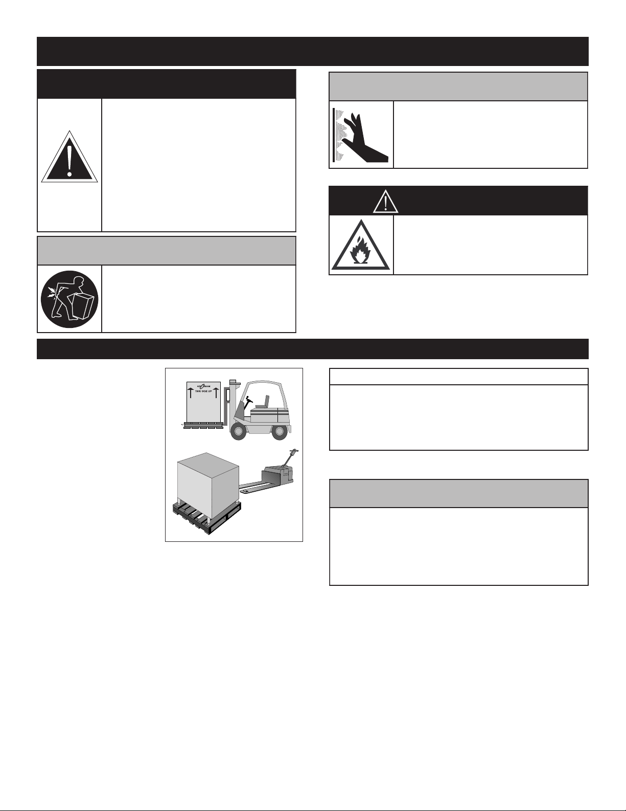
D A N G E R
IMPROPER INSTALLATION,
ALTERATION, ADJUSTMENT,
S
ERVICE, OR MAINTENANCE COULD
RESULT IN SEVERE INJURY, DEATH
OR CAUSE PROPERTY DAMAGE.
READ THE INSTALLATION,
OPERATING AND MAINTENANCE
INSTRUCTIONS THOROUGHLY
BEFORE INSTALLING OR SERVICING
THIS EQUIPMENT.
C A U T I O N
TO PREVENT PERSONAL INJURY,
USE CAUTION WHEN MOVING OR
LEVELING THIS APPLIANCE.
C A U T I O N
METAL PARTS OF THIS EQUIPMENT
BECOME EXTREMELY HOT WHEN IN
OPERATION. TO AVOID BURNS,
ALWAYS USE HAND PROTECTION
WHEN OPERATING THIS APPLIANCE.
D A N G E R
DO NOT store or use gasoline or other
flammable vapors or liquids in the
vicinity of this or any other appliance.
N O T E
If the appliance has been unplugged for an
extended period of time, the Real Time Clock may
require recharging. Turn main breaker to the unit
off for 10 seconds and then restore power.
For more information, see Error Code E-60 in
the Troubleshooting section of this manual.
S I T E I N S TA L L A T I O N
The Alto-Shaam cook
and hold oven must be
installed in a location
that will permit the
oven to function for its
intended purpose and
to allow adequate
clearance for
ventilation, proper
cleaning, and
maintenance access.
1. The oven must be installed on a stable and
level surface.
2. DO NOT install this appliance in any area
where it may be affected by any adverse
conditions such as steam, grease, dripping
water, high temperatures, or any other severely
adverse conditions.
3. DO NOT store or use any flammable liquids or
allow flammable vapors in the vicinity of this
oven or any other appliance.
4. This appliance must be kept free and clear of
any combustible materials.
5. This appliance must be kept free and clear of
any obstructions blocking access for
maintenance or service.
767-SK/I II, 1 767-SK/III , 280 0-S K/III INS TALL AT IO N /OP ERAT I ON /SE R VI C E MAN UAL PG . 3
CL E ARANC E RE Q UIREM E NTS
18" (457mm) minimum clearance at the back from heat
producing equipment. To protect the electronic
control, maintain sufficient side clearance to prevent
the control area from reaching any temperature at or
above 140°F (60°C).
Page 6
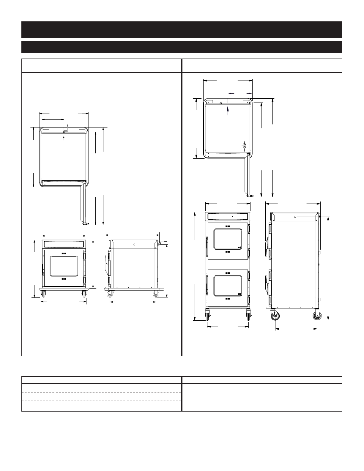
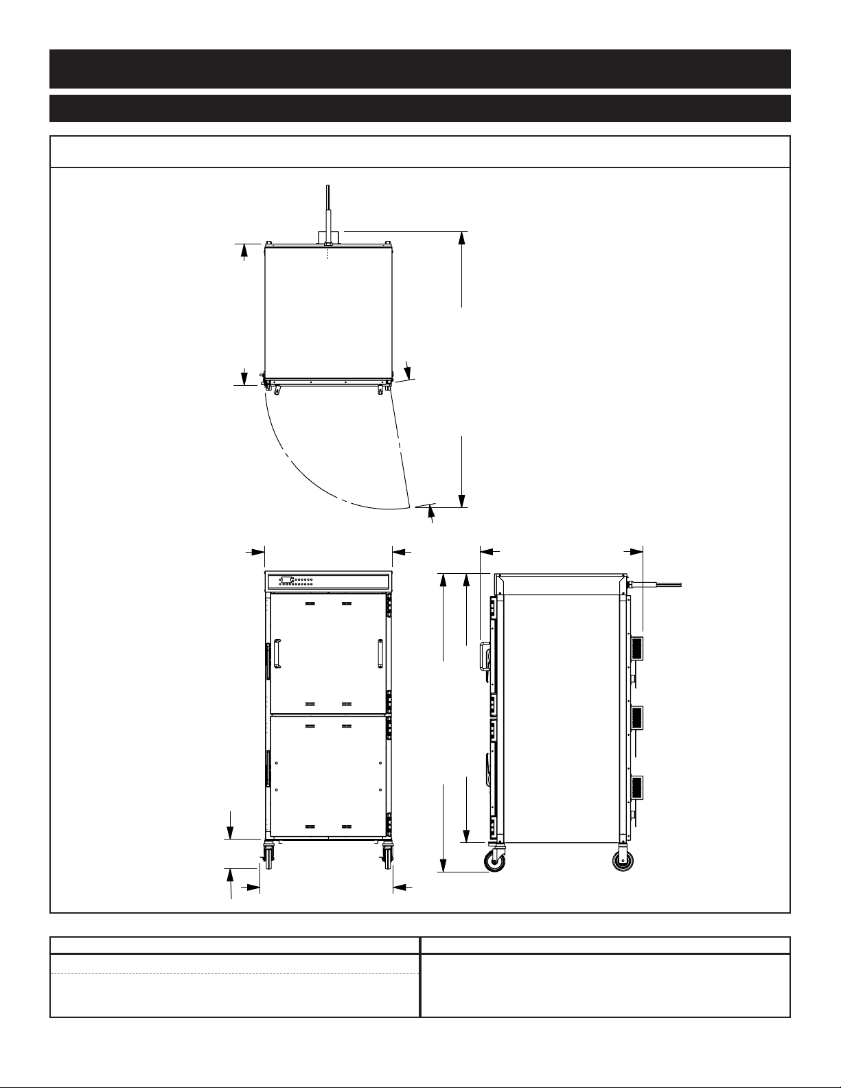
S I T E I N S TA L L A T I O N
28-5/8" (726mm)
Shown with
optional bumper
34-7/8" (886mm)
56-15/16" (1445mm)
E
lectrical
C
onnection
54-13/16" (1376mm)
12-7/8"
(327mm)
26-5/8" (676mm)
25-3/4" (654mm)
28-1/4" (717mm)
*31-13/16" (807mm) - with optional 2-1/2" casters
*35-1/4" (894mm) - with optional 5" casters
*34-7/16" (874mm) - with optional 6" legs
31-3/4" (805mm)
30-7/8" (784mm)
(electrical connection)
26-15/16" (683mm)
33-1/2" (851mm)
with 3-1/2" casters*
25-3/4"
(653mm)
62-3/8" (1583mm)
with 5
" Casters
23-5/8"
(600mm)
*60-15/16" (1548mm) - with optional 3-1/2" (89mm) casters
*62-1/2" (1589mm) - with optional 6" (152mm) legs
28-3/16"
(716mm)
54-3/4" (1390mm)
34-1/2" (876mm)
56-3/4" (1441mm)
with optional bumper
31-9/16"
(801mm)
59-1-2" (1511mm)
24-1/8"
(613mm)
12-7/8"
(326mm)
Electrical
Connection
Shown with
O
ptional
B
umper
767-SK/III 1767-SK/III
I N S T A L L A T I O N
WE I GHT
MODEL NET WEIGHT SHIP WEIGHT
767-SK/III 196 lb (89 kg) 216 lb (98 kg) EST.
1767-SK/III 359 lb (163 kg)
EST. 399 lb (181 kg) EST.
CA PACITY PER COM PA RTM E NT
100 lb (45 kg)
VO LU ME MAX IMU M
MAXIMUM
: 53 QUA RTS (67 LI TER S)
PG . 4 767-SK/I II, 1 767-SK/III , 280 0-S K/III INS TALL AT IO N /OP ERAT I ON /SE R VI C E MAN UAL
Page 7
I N S T A L L A T I O N
31-1/16" (789mm)
39-9/16" (1004mm)
7
2
-3
/8
" (1
8
3
8
m
m
)
32-3/8" (822mm)
6
7
-1
/1
6
" (1
7
0
2
m
m
)
30-11
/
16" (778mm)
6
6
-5
/1
6
" (1
6
8
4
m
m
)
6-
1/16"
(154mm)
34-1/8" (866mm)
Electrical
Connection
2-3/4" (71mm)
from top
C
L
S I T E I N S TA L L A T I O N
2800-SK/III
WE I GHT
MODEL NET WEIGHT SHIP WEIGHT
2800-SK/III 410 lb (186 kg) 575 lb (261 kg)
767-SK/I II, 1 767-SK/III , 280 0-S K/III
C A PA C I T Y
360 lb (163 kg)
VO L UME MAX I MUM
IN STAL L ATI O N/O PER ATIO N /S E RV I CE MA NU A L PG. 5
: 225 Q U ARTS (285 L I TER S )
MA X IMU M
Page 8

S I T E I N S TA L L A T I O N
OPTIONS AN D ACCESSORI ES 767-SK/III 1767-SK/III 2800-SK/III
Bumper, Full Perimeter 5010371 5010371 5008636
Carving Holder
ST EAM SHI P (CA FET ERI A) RO UND
I N S T A L L A T I O N
PR IME R IB
HL-2635
4459
HL-2635
4459
HL-2635
4459
Casters - 2 R
IGID
WIVEL W/BRAKE
, 2 S
5" (127mm)
3-1/2" (89mm)
2-1/2" (64mm)
5004862
STANDA RD
5008022
STANDA RD
5008017
—
STANDA RD
5008017
—
Door Lock with Key LK-2763 LK-2763 —
Drip Pan
ITH DRAIN
W
EXTRA DEEP
14831
—
14831
—
—
5007290
Legs, 6" (152mm) - SET O F FOU R
FL ANG ED
ST EMM ED
—
5011149
—
5011149
5004863
—
Pan Grid, Wire - 18" X 26" PAN IN SERT PN-2115 PN-2115 —
Pan Slides (230V ONLY) 5008240 5008240 —
Shelf, Stainless Steel
FL AT WIRE, REACH -IN
RI B RAC K
SH-2324
SH-2743
SH-2324
SH-2743
SH-27988
—
Stacking Hardware 5004864 — —
Wood Chips, bulk pack
Apple 20 lb (9 kg)
Cherry 20 lb (9 kg)
Hickory 20 lb (9 kg)
Maple 20 lb (9 kg)
WC-22543
WC-22541
WC-2829
WC-22545
WC-22543
WC-22541
WC-2829
WC-22545
HACCP Network Options
➥ HACCP Documentation
➥ HACCP with Kitchen Management
* REFER TO HACCP SPECIFICATION #9015 FOR APPLICABLE PART NUMBERS.
PG . 6 767-SK/I II, 1 767-SK/III , 280 0-S K/III INS TALL AT IO N /OP ERAT I ON /SE R VI C E MAN UAL
WC-22543
WC-22541
WC-2829
WC-22545
Page 9
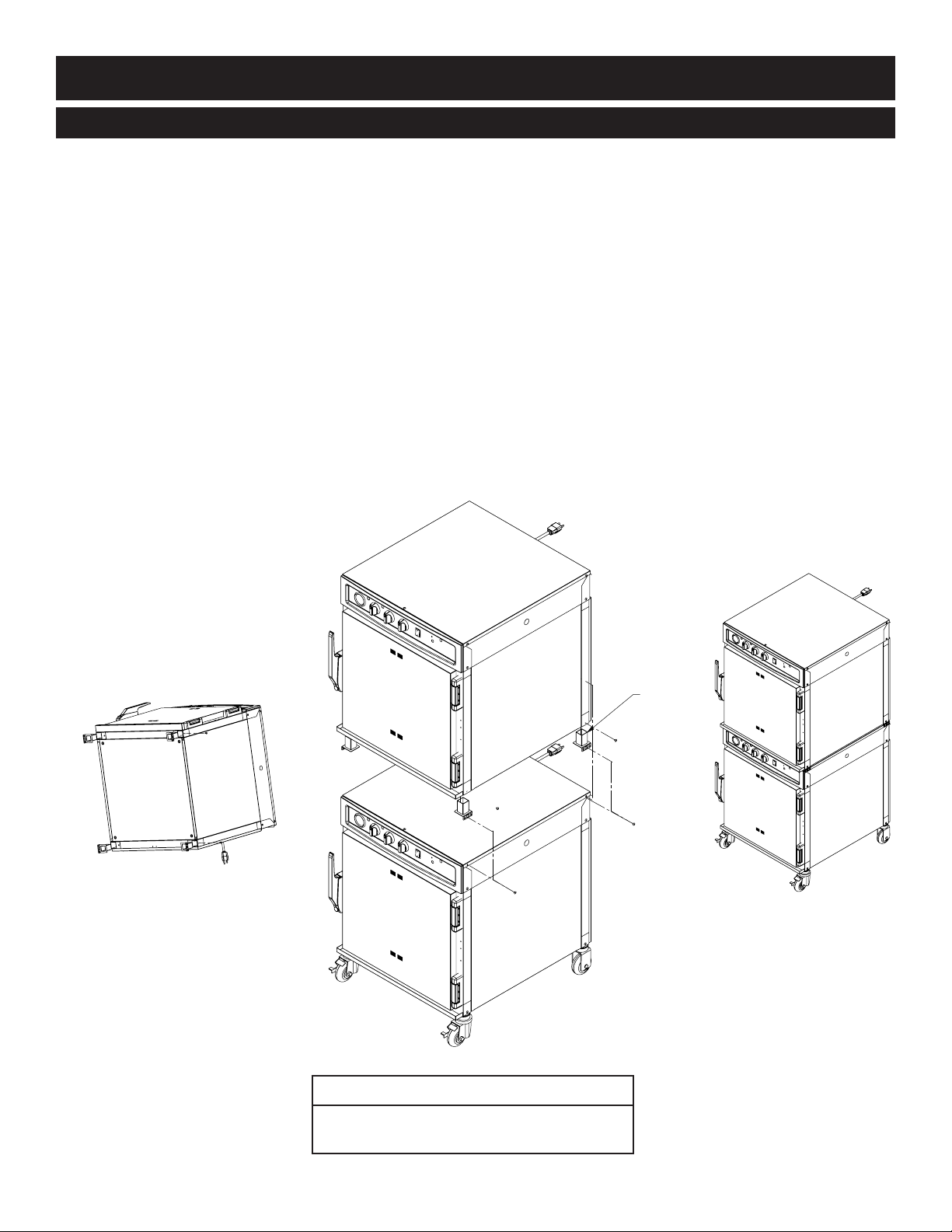
I N S T A L L A T I O N
CASTER SET
SCREW
TOP
MOUNTING
SCREWS
STACKING
POSTS
TOP
MOUNTING
SCREWS
STACKING INSTRUCTIONS
1) I f the two ap p l iances we re sh ipped to g ether from th e facto r y, the top unit wil l have the
ca s t e rs already removed. A stackin g kit will be included with the shi p m ent.
If casters need to be removed: lay the unit on its back, and remove the set screw on each caster. Pull the
casters out of the unit.
2) W h ile ap p l i ance is laid on its back, insert on e stac k i ng pos t in ea ch of the fo u r corners
of the up per uni t . Se c ure the sta c k i ng pos t s using one sc rew an d two flat wa shers th at
co m e with the st a c king ki t .
Not e : The flange on the stacking posts must face the outside of the unit.
3) R e move th e four top mo u n ting sc rews from th e lower unit. Place the up per ap p l iance,
wh i c h has the st a cking po s ts ins t a l led, on top of the bottom unit. Center the to p
un i t fro m fron t to back. Re-instal l the four sc rews th rough the fla n g e of the fo u r
sta c king po s t s.
S I T E I N S TA L L A T I O N
Stacking C onfigurat ions
767-SK/III with 767-SK/III, 750-TH/III,
750-TH-II, 767-SK, or 750-S
767-SK/I II, 1 767-SK/III , 280 0-S K/III INS TALL AT IO N /OP ERAT I ON /SE R VI C E MAN UAL PG . 7
Page 10
S I T E I N S TA L L A T I O N
W A R N I N G
RISK OF EL E CTRIC S HOCK.
Appliance must be secured
to building structure.
I N S T A L L A T I O N
A number of adjustments are associated with
nitial installation and start-up. It is important
i
that these adjustments be conducted by a qualified
service technician. Installation and start-up
adjustments are the responsibility of the dealer or
user. These adjustments include but are not
limited to thermostat calibration, door adjustment,
leveling, electrical hook-up and installation of
optional casters or legs.
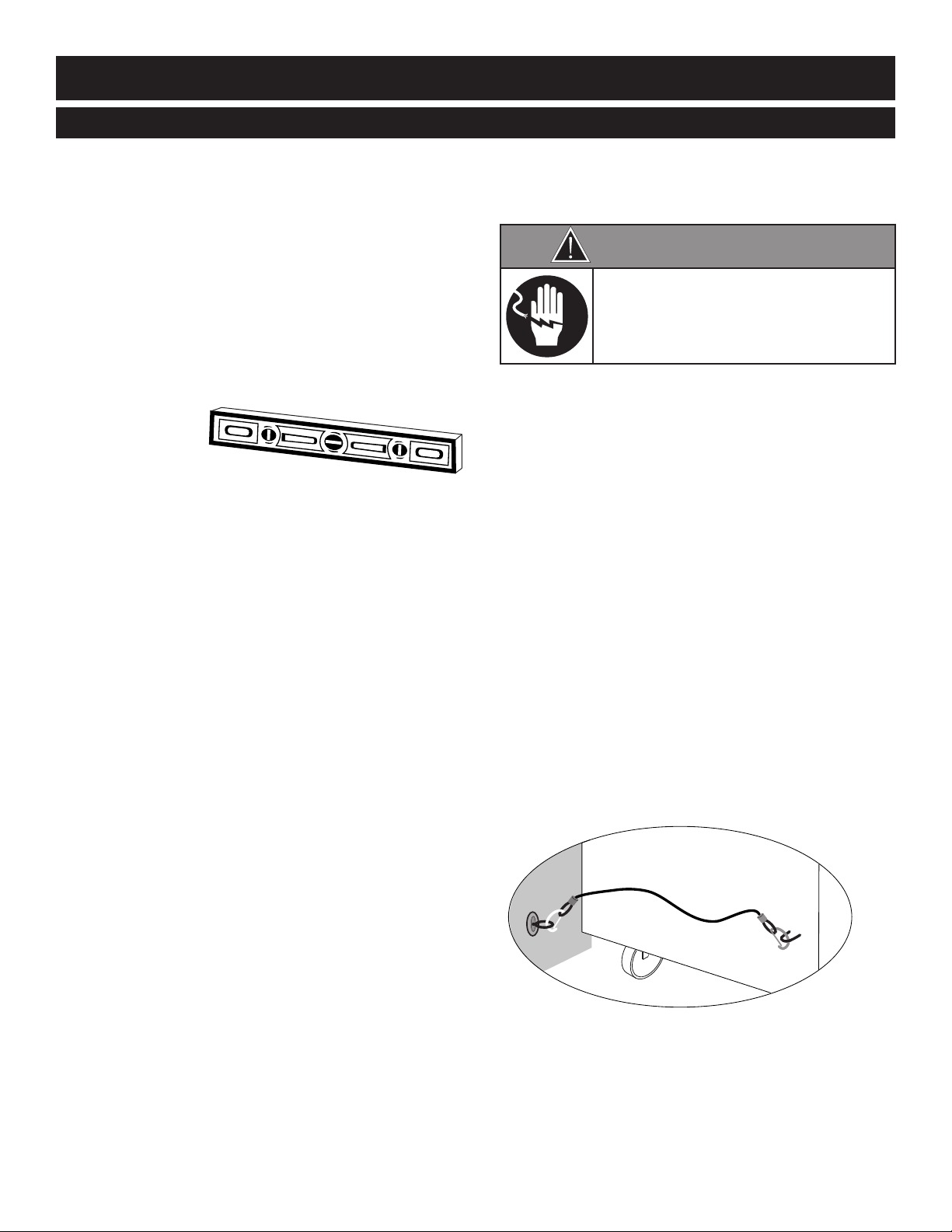
LEVELING
Level the oven
from side-to-side and
front-to-back with the use of a spirit level.
For ovens installed with casters, it is important
that the installation surface be level due to the
probability of frequent oven repositioning.
We recommend checking the level of the oven
periodically to make certain the floor has not
shifted nor the oven moved.
NOT E : Failure to properly level this oven can
cause improper function and will result
in the uneven baking with products
consisting of semi-liquid batter.
RESTRAINT REQUI REMENTS
—MOBILE EQ UIPMENT
Any appliance that is not furnished with a power
supply cord but that includes a set of casters must
be installed with a tether. Adequate means must
be provided to limit the movement of this
appliance without depending on or transmitting
stress to the electrical conduit. The following
requirements apply:
1. Maximum height of casters is 6" (152mm).
2. Two of the casters must of be the locking type.
Such mobile appliances or appliances on mobile
3.
stands must be installed with the use of a flexible
connector secured to the building structure.
A mounting connector for a restraining device is
located on the lower back flange of the appliance
chassis or on an oven stand, approximately 18"
(457mm) from the floor. A flexible connector is not
supplied by nor is it available from the factory.
PG . 8 767-SK/I II, 1 767-SK/III , 280 0-S K/III INS TALL AT IO N /OP ERAT I ON /SE R VI C E MAN UAL
Page 11
I N S T A L L A T I O N
W A R N I N G
FAIL U R E T O PROPE R LY I NSTAL L
TH E DRIP T RAY C A N O R WILL
CA U S E M A J OR E Q U IPM E N T
DA M A GE A N D WIL L RESULT I N A
LE A K AGE H AZAR D THAT C A N
CA U S E P E R SONA L INJURY.
S I T E I N S TA L L A T I O N
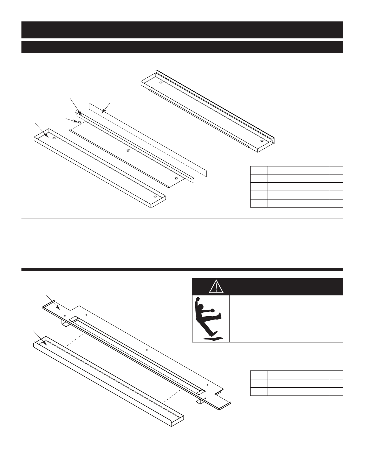
DRIP TRAY INSTALLATION INSTRUCTIONS - 767 & 1767-SK/III
1. Poke holes through double-sided tape which is attached to the back of drip tray holder .
2. Remove backing on double-sided tape .
3. Put screws through holes and attach drip tray holder to unit.
4. Optional - apply a line of food-grade silicone caulk along top edge of drip tray holder to seal.
5. Place drip tray in drip tray holder .
Item Description Qty
1 Double-Sided Tape 1
2 Drip Tray Holder 1
3 8-32 x 1/4" Phil Screw 3
4 Drip Tray 1
2800-SK/ III
Slide drip tray
under drip tray platform .
into bracket
767-SK/I II, 1 767-SK/III , 280 0-S K/III INS TALL AT IO N /OP ERAT I ON /SE R VI C E MAN UAL PG . 9
Item Description Qty
1 Drip Tray 1
2 Drip Tray Bracket 1
Page 12
I N S T A L L A T I O N
D A N G E R
ENSURE POWER SOURCE
MATCHES VOLTAGE STAMPED
ON APPLIANCE NAMEPLATE.
D A N G E R
To avoid electrical shock, this
appliance MUST be adequately
grounded in accordance with local
electrical codes or, in the absence of
local codes, with the current edition
of the National Electrical Code
ANSI/NFPA No. 70. In Canada, all
electrical connections are to be
made in accordance with CSA C22.1,
Canadian Electrical Code Part 1 or
local codes.
D A N G E R
ELECTRICAL CONNECTIONS MUST
BE MADE BY A QUALIFIED SERVICE
TECHNICIAN IN ACCORDANCE WITH
APPLICABLE ELECTRICAL CODES.
E L E C T R I C A L C O N N E C T I O N
The appliance must be installed by a qualified
ervice technician. The oven must be properly
s
grounded in accordance with the National
Electrical Code and applicable local codes.
Plug the unit into a properly grounded receptacle
ONLY, positioning the unit so that the plug is
easily accessible in case of an emergency. Arcing
will occur when connecting or disconnecting the
unit unless all controls are in the “
OF F” position.
Proper receptacle or outlet configuration or
permanent wiring for this unit must be installed
by a licensed electrician in accordance with
applicable local electrical codes.
E L E C T R I C A L - 76 7 - S K / I I I
VOLTAGE PH ASE CYC LE / HZ A MPS kW AWG
208-240 (AGCY)1 60 16.0 3.85
at 208 1 60 15.5 3.21
at 240 1 60 17.8 4.27
230 1 50 16.0 3.68
CO RD
NO PL UG
CE E 7/7
220-230V
PL UG
230 V:
o prevent an electrical shock hazard between
T
the appliance and other appliances or metal
parts in close vicinity, an equalization bonding
stud is provided. An equalization bonding
lead must be connected to this stud and the
other appliances / metal parts to provide
sufficient protection against potential
difference. The terminal is marked with the
following symbol.
NOT E : 230V appliances must be connected to an
electrical circuit that is protected by an
external GFCI outlet.
E L E C T R I C A L - 17 6 7 - S K / I I I
VOLTAGE PH ASE CYC LE / HZ A MPS kW AWG
208-240 (AGCY)1 60 32.0 7.70
at 208 1 60 30.9 6.43
at 240 1 60 35.6 8.55
230 1 50 34.1 7.86
E L E C T R I C A L - 28 0 0 - S K / I I I
VOLTAGE PH ASE CYC LE / HZ AMPS kW AWG
208 1 60 43.1 8.96 CORD, NO PL UG
240 1 60 38.8 9.31 CORD, NO PLUG
230 1 50 37.1 8.54 NO CORD OR PLUG
208 3 60 27 8.96 NO CORD OR PLUG
240 3 60 27 9.31 NO CORD OR PLUG
380-415 (AGCY)3 50 15.5 9.31 NO CORD O R PLUG
NO CO RD
OR PL UG
NO CO RD
OR PL UG
Wire di agram s a re locat ed ins ide t he bon net of t he uni t.
PG
. 1 0 767-SK/I II, 1 767-SK/III , 280 0-S K/III INS TALL AT IO N /OP ERAT I ON /SE R VI C E MAN UAL
Page 13
O P E R A T I N G I N S T R U C T I O N S
C A U T I O N
METAL PARTS OF THIS EQUIPMENT
BECOME EXTREMELY HOT WHEN IN
OPERATION. TO AVOID BURNS,
ALWAYS USE HAND PROTECTION
WHEN OPERATING THIS APPLIANCE.
D A N G E R
AT NO TIME SHOULD THE INTERIOR
OR EXTERIOR BE STEAM CLEANED,
HOSED DOWN, OR FLOODED WITH
WATER OR LIQUID SOLUTION OF
ANY KIND. DO NOT USE WATER JET
TO CLEAN.
SEVERE DAMAGE OR
ELECTR I C A L HA Z A R D
COULD RESULT.
WARRANTY BECOMES VOID IF
APPLIANCE IS FLOODED
D A N G E R
DISCON N E C T U N IT F ROM
POWER SOURCE BEFORE
CLEANI N G OR SE RVICING .
U S E R S A F E T Y I N F O R M A T I O N
S T A R T- U P O P E R A T I O N
BEF O R E INITIAL USE:
Interior oven surfaces must be heated to remove
surface oils and the accompanying odor produced
during the first use of the oven.
1. Wipe all wire shelves, side racks and the full oven
interior with a clean, damp cloth. Install the oven
side racks, oven shelves, and external drip tray.
Shelves are installed with the curved edge toward
the back of the oven. Insert the drip pan on the
interior bottom surface of the oven.
The Alto-Shaam cook and hold oven is intended
for use in commercial establishments by qualified
operating personnel where all operators are
familiar with the purpose, limitations, and
associated hazards of this appliance. Operating
instructions and warnings must be read and
understood by all operators and users.
2. • Close the oven doors
• Press and release control ON/OFF key.
• Press the COOK key.
• Press the up and down arrows to set the cooking
temperature to 300°F (149°C).
3. • Press the TIME key.
• Press the up and down arrows to set the
cooking time to approximately 2 hours.
• Allow the oven to cycle for approximately
2 hours or until no odor is detected.
A U D I B L E S I G N A L S
OVEN BEEPING indicates a response, mode changes, and error conditions.
One brief beep - response to a key being pressed.
Two brief beep s - informative beep that indicates that something has been changed, such
Three brief beeps - indicates the oven is done preheating, the probe has exceeded
Four brief beep s - indicates an error. Refer to the Trouble Shooting section of this manual.
as the user entering a volume change, entering a temperature scale
change, etc.
set-point in cold smoking, the door has been open too long, or the
control is unlocked.
767-SK/I II, 1 767-SK/III , 280 0-S K/III INS TALL AT IO N /OP ERAT I ON /SE R VI C E MAN UAL PG . 11
Page 14
--:--
O P E R A T I N G I N S T R U C T I O N S
Power ON
Upper
Cavity
ON/OFF
Indi cator
Lower
Cavity
ON/OFF
767-SK/III
1
Control
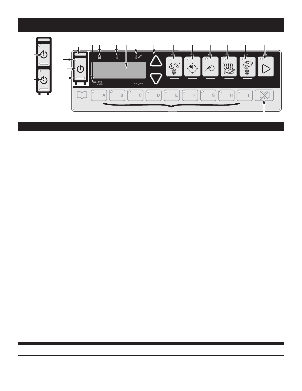
CONTROL FE ATURES
1. On/Off Key
The on/off control system key operates the functions
of the control panel. If there is any power loss during
operation, the on/off indicator light will flash. To
clear, push key and release.
2. Cook Key — Temperature range 200° to 325°F
(93° to 162°C)
Used to select cooking mode and to review the cook
temperature setting.
3. Time Key — Maximum time 24 hours
Used to select cook time and to review set time.
4. Probe Key — Temperature range 50° to 195°F
(10° to 91°C)
Used to select internal product probe temperature
mode and to review probe temperature setting.
5. Hold Key — Temperature range 60° to 205°F
(15° to 96°C)
Used to select food holding mode and to review set
holding temperature.
6. Smoker Key — Time range 0 to 4 hours
Used to select warm smoke or cold smoke and to
review the smoke time remaining.
7. Lock Indicator
When illuminated, this symbol indicates settings used
in the cooking sequence are locked and cannot be
changed.
8. Halo Heat Indicator
When the oven is preheating, the Halo Heat indicator
will illuminate during preheating and remain steady
until the oven reaches the set cooking temperature.
When the temperature has stabilized, the indicator will
illuminate periodically as the oven calls for heat.
9. Oven Preheat Light
Illuminates until the oven is preheated or in ready mode.
10. LED Display
11. Ready Indicator Light
12. Up and Down Arrows
13. Start Key
14. Green Indicator Lights
15. Amber Indicator Lights
16. Preset Program Keys
17. Cancel Key
Indicates interior oven air temperature, internal
product probe temperature, time, or when used in
conjunction with other keys, will review
original cooking, holding and probe temperature
settings. The display will also indicate various
programming and diagnostic information.
Illuminates when the oven has finished preheating.
Used to increase or decrease set time, including
cooking, holding and probe temperature settings.
Used to initiate a selected mode sequence when
p re ssed and rele ased . You may stop any mode of
operation by pre ssing a nd ho ld ing the Start Key until
you hear a 2-second beep.
Located within each function key, the green light
functions as an operator prompt indicating additional
operator action is required and also identifies current
mode of operation.
Located below the Cook, Time, Probe and Hold Keys,
these indicators will illuminate to identify the current
mode of operation and allows the operator to identify
the information currently shown in the LED display.
Provides memory storage and operation of up to eight
operator set cooking programs for specific products
(A thru H). I enables locking abilities.
Used to erase a program from memory storage.
IMP ORTANT
Do not use the oven if the controls are not properly functioning. Refer to the Troubleshooting Guide located in
PG . 12 767-SK /III, 1767-SK/I II, 2 800-SK/III I N STA L LAT I ON/OPE R ATI O N/S ERV ICE MANU AL
this manual or call an authorized service technician.
Page 15

O P E R A T I N G I N S T R U C T I O N S
O P E R AT I N G F E AT U R E S & F U N C T I O N S
To stop an operation at any time — Press and hold the
START Key until the control beeps for two seconds,
indicating the operation has been cancelled. The oven
will remain in a power-on state.
To turn oven control panel off — Press and hold the
ON/OFFKey until the oven beeps. The ON/OFFindicator
light will go out.
Door open indicator — Display will flash “door” and a
triple beep will alert the user. Press ON/OFFkey to
acknowledge error and disable triple beep.
Arrow Keys:
Cook, Hold and Probe Temperature set points can be
adjusted by 1° when pressing the AR
in steps of 10°, p ress and hold the TE
ROW
AR
Key at the same time.
ROW
Keys. To adjust
MPERATURE
Key and
The Time setting is adjusted in increments of 1 minute by
pressing the ARROW Keys. To make adjustment in steps of
10 minutes, p re ss and h o ld the TIME Key and ARROW Key
at the same time.
Green and Amber Indicators:
Each program key includes a green
Green
light which indicates a requirement
for additional programming by the
operator or the current operational
state of the oven.
Amber
The COOK, TIME, PROBE, and HOLD keys include an amber
indicator light to identify the information being displayed.
Power Fail Detect:
If the power were to fail for any reason while heating, the
control will retain, in memory, the programmed operating
conditions. When power is restored, the control will
resume operating from the point where it was interrupted
and the ON/OFF indicator light will flash, indicating that
such an event did occur. The operator can acknowledge
the power failure by pressing the ON/OFF key. Pressing
the key will display the amount of time that the power
has been off. The control will stop counting the amount
of time the power has been off when it has been off for
more than 24 hours.
NOTE: If such an event has occurred, it is strongly
recommended that you ensure the food is safe for
consumption according to local health regulations.
Display High/Low Probe Temperatures:
To observe the recorded maximum or minimum probe
temperature when cooking by probe, press the following
keys while the probe remains in the product:
Highest Temperature: Press PROBE Key and UP ARROW
Key at same time.
Lowest Temperature: Press PROBE Key and DOWN ARROW
Key at same time.
767-SK/I II, 1 767-SK/III , 280 0-S K/III INS TALL AT IO N /OP ERAT I ON /SE R VI C E MAN UAL PG . 13
Probe Usage:
When the oven probe remains inserted in the probe
bracket, the LED temperature display will indicate the
mbient air temperature inside the oven. To use the
a
probe for cooking remove it from the bracket and wipe
the full length of the metal probe with a disposable
alcohol pad to clean and sanitize before using.
Only the tip of the probe senses the internal product
temperature; therefore, it is important the tip be placed
correctly in the product for internal temperature accuracy.
Push the probe tip halfway into the product, positioning
the tip at the center of the food mass. When inserting the
probe into solid foods such as meat roast or poultry
breasts, push the probe in from a straight downward
position or in from the side to the center position. If
placing into a semi-liquid or liquid product, the probe
cable must be secured to keep the probe positioned
properly. Do not let the probe tip touch the edges, bottom
or side of a container. Tape the probe cable to the lip or
edge of the container.
NOTE: When cooking by probe, insert the probe
into the raw product after the oven has been
preheated.
WAIT ONE FULL MINUTE
temperature to decrease to the internal temperature
of the product. Press the start button to begin the
cooking process after this probe temperature
adjustment period. A false probe reading of the
internal product temperature will cause the oven to
default to a holding temperature.
to allow the probe
Probe Calibration:
1. To verify product probe calibration, place the probe in a
warm glass of water along with a quality independent
digital thermometer and press the probe key for five (5)
seconds. Compare readings.
2. If calibration is required, the unit must be in the power
up hold mode. From the off state turn the unit on. The
unit will begin to operate in the power up hold mode,
press the probe key for eight (8) seconds until the unit
beeps twice and a temperature is displayed. Adjust the
probe temperature to match the independent probe by
pressing the up or down arrows to increase or decrease
the temperature. Repeat step 1 to verify.
3. Repeat steps 1 and 2 to verify the probe calibration
as necessary.
Page 16

O P E R A T I N G I N S T R U C T I O N S
C A U T I O N
TO MA INTAI N SAF E TEM PER ATURE
LEVE LS, CO LD FO O D FOR
RETH ERM A L IZATION OR R EHE ATING
MUST N EVE R BE ADDE D TO THE OVE N
WHIL E HOT FO ODS A RE BEIN G HEL D.
Cook/Hol d /Smoke Ins tructions
Press and release control ON/OFF key. The oven will beep for one second and power to the unit
will be indicated by an illuminated green indicator light located in the upper left corner of the
O
ey. The oven will begin operating in the hold mode. The amber H
ON/
illuminated and the last set hold temperature will be displayed.
To set Cook tem p erature — Press C
set cooking temperature is displayed. To change the cook temperature, press the UP or DO
ARROW Keys.
If cooking by time — press the TIME Key. The green TIME indicator will illuminate and the last set
cooking time will be displayed. To change the set time, press the UP or DOWN ARROW Key. The
display will alternate between the set temperature and the elapsed time.
If cooking by probe — press the PROBE Key. The green PROBE indicator will illuminate and the last
set internal product temperature will be displayed. To change the set temperature, press the UP
or DOWN ARROW Key. The display will alternate between the set temperature, the elapsed time,
and the probe temperature.
To set Hold temperature — Press the HOLD Key. The green cook indicator light will remain
illuminated. To change the hold temperature, press the UP or DOWN ARROW Key. The display will
alternate between the set hold temperature and the amount of time the product has been in the
hold mode. Oven will remain in the HOLD mode until the ON/OFF key is pressed.
F
F
k
ndicator will be
LD
O
i
OK
O
Key. Oven preheat indicator will illuminate and the last
WN
To set Smoke time (hot smoke) — Press SMOKER Key. To set the smoke time desired, use UP or
DOWN ARROW key. The last set time will be displayed. Se e f o llo w ing p age fo r a d d itio nal Sm o k ing
Pro ce d ure s.
Press STA RT key to beg in cooking cycle.
To Coo k/Hold/S m oke using P res et Menu Keys
Press Desired PRESET Key (A throug h H). PRESET Keys with stored cooking programs will have
green indicator illuminated. The oven will automatically enter preheat mode. Oven will beep
periodically when it has reached a preheat ready state, and both the Ready and Start indicator
lights will flash. To program a preset menu key, see Programming a Preset in this manual.
Press S
TART key to beg in cooking cycle.
PG . 14 767-SK /III, 1767-SK/I II, 2 800-SK/III I N STA L LAT I ON/OPE R ATI O N/S ERV ICE MANU AL
Page 17

O P E R A T I N G I N S T R U C T I O N S
Pro gramming a P re set
Select the product to be programmed and begin programming with the oven control power OFF.
ress and release control ON/O
P
will be indicated by an illuminated green indicator light located in the upper left corner of the
N/OFF key. The oven will begin operating in the hold mode. The amber HOLD indicator will be
O
illuminated and the last set hold temperature will be displayed.
To set Cook tem p erature — Press COOK Key. Oven preheat indicator will illuminate and the last
set cooking temperature is displayed. To change the cook temperature, press the UP or DOWN
ROW
AR
If cooking by time — press the TIME Key. The green TIME indicator will illuminate and the last set
cooking time will be displayed. To change the set time, press the UP or DOWNAR
display will alternate between the set temperature and the elapsed time.
If cooking by probe — press the PROBE Key. The green PROBE indicator will illuminate and the last
set internal product temperature will be displayed. To change the set temperature, press the UP
or DOWN ARROW Key. The display will alternate between the set temperature, the elapsed time,
and the probe temperature.
To set Hold temperature — Press the HOLD Key. The green cook indicator light will remain
illuminated. To change the hold temperature, press the UP or DOWN ARROW Key. The display will
alternate between the set hold temperature and the amount of time the product has been in the
hold mode. Oven will remain in the HOLD mode until the ON/OFF key is pressed.
To set Smoke time — Press SMOKER Key. To set the smoke time desired, use UP or DOWN ARROW
key. The last set time will be displayed.
Keys.
ey. The oven will beep for one second and power to the unit
F
F
k
ROW
Key. The
Select a letter code for the product programmed by the previous steps. Press and hold the selected
PRESET key for two seconds. When the preset has been saved, you will hear a one second beep and the
preset light will illuminate.
Note: Only one preset can be programmed at a time. If programming an additional preset is
desired, the unit must be started and stopped either by cycling the power to the cavity or by
pressing the START/STOP key. The last PR ESE T Key used will be the oven cooking run sequence
for the next product to be programmed. Settings can be manually changed for the next
product and an alternate pre-programmed letter key selected.
Erasing a Preset
To erase a program, the oven must be in either the power-up hold mode or in the preheat mode. The oven
cannot be running a PRESE T Menu program.
When the oven is in the power-up hold mode or in the preheat mode, press and hold the CANCEL Key and
then the appropriate letter PRE SET Key to be erased for two seconds. When the preset has been erased the
oven will beep for one second.
IMPORTA NT - After programming a specific product into memory in a programmable preset
key, it is very important to make a written permanent record of the product and the program letter
assigned. Menu card (PE-23384) is provided for this purpose.
767-SK/I II, 1 767-SK/III , 280 0-S K/III INS TALL AT IO N /OP ERAT I ON /SE R VI C E MAN UAL PG . 15
Page 18

O P E R A T I N G I N S T R U C T I O N S
W A R N I N G
THE USE OF IM PROPE R
MATE RIA LS FOR THE SMO KING
FUNCTIO N C OUL D R ESU LT IN
DAM AGE, HAZAR D, EQUI PME NT
F
AIL U RE OR COU LD REDUCE THE
OVE RALL LIF E O F THE OVE N.
DO NOT US E S AWDUST
FOR SMO KIN G.
DO NOT US E WOO D C HIP S
SMALLER THAN THU MBN AIL SIZE .
Preparation
Adjust the inside door vents per the individual
cooking procedure selected. Always keep door
vents closed when cooking with the smoking
function. Insert drip pan on the bottom of the
oven cavity.
Wood Chips
Soak one full tray of wood chips in water for 5 to
10 minutes. Shake off excess water, and place the
moistened chips in the wood chip tray of the
smoker oven. Replace the container in the oven.
Wood Chip Tray
Hot Smoke Procedure
Press and release power switch ON/OF
Control Key.
Press and set COOKthermostat to required
cooking temperature.
F
Cold Smoke Procedure
To Enter Cold Smoke Mode
Press and release power switch ON/OFF
Control Key.
Press and hold the SM
of 3 seconds.
Press and set TI ME or PROB E.
To Set Cold Smoke Holding
Temperature
Press and set HO LD thermostat to required
holding temperature.
The Oven is automatically programmed to
preheat to the set cooking temperature. The
oven will produce an audible signal when
fully preheated.
Prepare product for cooking.
Load product on shelves.
To Set Smokin g T i m e
Press the SMOK ER Key.
Press the U
P and DOWN ARRO W KEY S to
select the smoke time in minutes.
The temperature will default to the last
smoke holding temperature set by the user.
The holding temperature range is
14°F to 205°F (-10°C to 96°C).
To increase this default temperature, press
the HOL D KEY and press the UP ARRO W to set
a higher default temperature.
To Set Smoking Verification
Temperature (IF DES IR ED )
Press the PR OBE KE Y
Press the UP and DO WN ARRO W KEY S
to select the verification temperature. The probe
range is 14°F to 195°F (-10°C to 91°C).
Press START.
No te: Th e sm o k ing tim e r ac tiv ate s th e
h e a tin g e le m e nt lo c a te d w ith in th e
w o o d ch ip co nta ine r w h e n in e ith e r a
co o k o r h o ld m o d e . Th e sm o k e
e le m e nt w ill no t turn o n during
p re h e a t o r rea d y mo d e s . A fu ll wo o d
ch ip c o n ta in e r will p ro d uc e sm o k e
fo r a pe rio d o f ap p ro xim a te ly 1 h o u r,
e ve n tho u gh th e tim e r ca n g o p a st
o ne ho u r.
This will incorporate the probe into the coldsmoking process and the control will alarm if the
temperature exceeds the probe set point.
To Set Smoking Time
Press the SMOK ER Key.
Press the UP and DOWN ARROW KE YS to
select the smoke time in minutes.
Prepare product for smoking.
Place stainless steel tray filled with ice on
shelf above the smoker tray.
For maximum product tenderizing and to reduc e labor
during peak preparation hours, products can be
These instructions are basic operational guidelines only.
For complete instructions, see the HALO HEAT
Guide to Low Temperature Cooking and Holding
PG . 16 767-SK /III, 1767-SK/I II, 2 800-SK/III I N STA L LAT I ON/OPE R ATI O N/S ERV ICE MANU AL
cooked and held overnight.
provided with the oven.
Taste preference Minimum Smoking time
Light Smoke Flavor 10 min.
Medium Smoke Flavor 30 min.
Heavy Smoke Flavor 40 min.
Very Heavy Smoke Flavor 60 min.
Extra Heavy Smoke Flavor 80 min.
Load product on shelves.
Press START.
OKER
Key for a period
Page 19

O P E R A T I N G I N S T R U C T I O N S
--:--
U S E R O P T I O N S
Preset
Lock
PRES E T Key s Lock a nd Unlock
PR ESE T Keys A through H can be locked in order to
prevent storing, altering or erasing a program.
To lock the PRES ET Keys, press and hold the "I" Key
until the oven beeps. Release the “I” key. The green
indicator on the "I" key will illuminate. Oven PR ESET
Keys A through H are now locked.
No te : Only the oven PRESE T keys A through H are
affected by this lock-out in order to also allow
the oven to be used with the unprogrammed
Cook, Probe, or Hold modes.
To unlock the PR ESE T Keys, press and hold the
CA NCE L Key along with the "I" Key for two seconds
until the "I" key light no longer illuminates. Release
all keys. The oven preset keys are now unlocked.
Fahrenheit or Celsius Selection
With the control in the off mode,
pre ss and hold the UP AR ROW Key until
the display shows the current selection.
Press the up or down buttons to toggle
between the two options. After each
change the button must be released. The display
must clear before the procedure can be repeated.
Control Panel L ock and Unl o ck
The control panel can be locked at any time in order to
prevent inadvertent or accidental setting changes.
To lock the control panel, press and hold the
UP ARROW Key and then press the ON/OFF Key.
You will hear a brief beep and the panel lock
indicator will illuminate. Release all keys.
The oven's control panel is now locked.
Note: The control panel is now fully locked with the
exception of the ON/OFF Key and ARROW keys.
You will be unable to turn the oven control off at
this point.
To unlock the control panel, press and hold the DOWN
ARROW Key and then press the ON/OFF Key. You will hear
three beeps and the panel lock indicator will extinguish.
Release all keys. The panel is now unlocked and ready for
normal use.
Beeper Vo l ume Select ion
With the control in the off mode,
press and hold the DOWN ARROW Key
until the display shows the current control
volume. Press the UP or DOWN ARROW Key
to cycle through the four options
(0 = Off, 1 = Low, 2 = Mid, 3 = High).
767-SK/I II, 1 767-SK/III , 280 0-S K/III INS TALL AT IO N /OP ERAT I ON /SE R VI C E MAN UAL PG . 17
Page 20

O P E R A T I N G I N S T R U C T I O N S
H O L D I N G T E M P E R A T U R E R A N G E
ME AT FAHRENHEIT CELSIUS
BE EF ROA S T — R are 1 30 °F 54 °C
BE EF ROA S T — Med/Well Done 15 5° F 6 8° C
BE EF BRI S KE T 1 60 ° — 175 °F 71° — 79 °C
C
OR N B EE F
1
60 ° — 175 °F
7
1° — 79 °C
PAS TR AM I 16 0° — 17 5° F 71 ° — 79° C
PR IM E R IB — Rar e 13 0° F 5 4° C
S
TE AK S — Broi le d/ Fr ie d
1
40 ° — 160 °F
6
0° — 71 °C
R
IB S — Bee f o r P ork
1
60 °F
7
1° C
VE AL 16 0° — 17 5° F 71 ° — 79° C
H
AM
1
60 ° — 175 °F
7
1° — 79 °C
P
OR K
1
60 ° — 175 °F
7
1° — 79 °C
L
AM B
1
60 ° — 175 °F
7
1° — 79 °C
PO U LTRY
CH IC KE N — Fr ie d/ Ba ke d 16 0° — 17 5° F 71 ° — 79° C
D
UC K
1
60 ° — 175 °F
7
1° — 79 °C
T
UR KE Y
1
60 ° — 175 °F
7
1° — 79 °C
GE NE RA L 16 0° — 17 5° F 71 ° — 79° C
FI S H/ S EA F OO D
F
IS H — Bak ed/ Fr ie d
1
60 ° — 175 °F
7
1° — 79 °C
L
OB ST ER
1
60 ° — 175 °F
7
1° — 79 °C
SH RI MP — Fr ie d 16 0° — 17 5° F 71 ° — 79° C
B
AK E D GO OD S
B
RE AD S/ RO LLS
1
20 ° — 140 °F
4
9° — 60 °C
MI S CE L LA N EO U S
C
AS SE RO LE S
1
60 ° — 175 °F
7
1° — 79 °C
DO UG H — Proo fi ng 80 ° — 100 °F 2 7° — 38 °C
EG GS —Fr ied 15 0° — 16 0° F 66 ° — 71° C
FR OZ EN ENTR EE S 16 0° — 17 5° F 71 ° — 79° C
HO RS D'O EUV RE S 16 0° — 18 0° F 71 ° — 82° C
PAS TA 16 0° — 18 0° F 71 ° — 82° C
PI ZZ A 16 0° — 18 0° F 71 ° — 82° C
PO TATOE S 18 0° F 8 2° C
PL ATE D M EA LS 14 0° — 16 5° F 60° — 7 4° C
SA UC ES 14 0° — 20 0° F 60 ° — 93° C
SO UP 14 0° — 20 0° F 60 ° — 93° C
VE GE TAB LE S 160 ° — 175 °F 7 1° — 79° C
TH E H OL D I NG T E M PE R AT UR E S LI S T ED A R E SU G G ES T E D
GU I D EL I NE S O N LY. AL L F O O D HO L D IN G S HO U L D BE B A SE D O N
IN T E RN A L PR O D UC T T EM P E RA TU R E S . A LWAY S F O LL O W L O C A L
HE A LTH ( H YG I E NE ) R EG U L AT IO N S FO R A L L I N T ER N A L
TE M P ER AT U RE R E QU I R EM E N TS .
General Hol ding Guideline
hefs, cooks and other specialized food service
C
personnel employ varied methods of cooking.
Proper holding temperatures for a specific food
product must be based on the moisture content of
the product, product density, volume, and proper
serving temperatures. Safe holding temperatures
must also be correlated with palatability in
determining the length of holding time for a
specific product.
Halo Heat maintains the maximum amount of
product moisture content without the addition of
water, water vapor, or steam. Maintaining maximum
natural product moisture preserves the natural
flavor of the product and provides a more genuine
taste. In addition to product moisture retention, the
gentle properties of Halo Heat maintain a consistent
temperature throughout the cabinet without the
necessity of a heat distribution fan, thereby
preventing further moisture loss due to evaporation
or dehydration.
When product is removed from a high
temperature cooking environment for immediate
transfer into equipment with the lower temperature
required for hot food holding, condensation can
form on the outside of the product and on the inside
of plastic containers used in self-service applications.
Allowing the product to release the initial steam and
heat produced by high temperature cooking can
alleviate this condition. To preserve the safety and
quality of freshly cooked foods, however, a
maximum of 1 to 2 minutes must be the only time
period allowed for the initial heat to be released
from the product.
Most Halo Heat Holding Equipment is provided
with a thermostat control between 60° and 200°F
(16° to 93°C). If the unit is equipped with vents,
close the vents for moist holding and open the vents
for crisp holding.
PG . 18 767-SK /III, 1767-SK/I II, 2 800-SK/III I N STA L LAT I ON/OPE R ATI O N/S ERV ICE MANU AL
Page 21

C A R E A N D C L E A N I N G
PR O T E C T I NG STAIN L E S S S T E EL SURFACES
It is important to guard against
corrosion in the care of
stainless steel surfaces.
Harsh, corrosive, or
inappropriate chemicals can
completely destroy the
protective surface layer of stainless steel.
Abrasive pads, steel wool, or metal implements
will abrade surfaces causing damage to this
protective coating and will eventually result in
areas of corrosion. Even water, particularly hard
water that contains high to moderate
concentrations of chloride, will cause oxidation
and pitting that result in rust and corrosion. In
addition, many acidic foods spilled and left to
remain on metal surfaces are contributing factors
that will corrode surfaces.
Proper cleaning agents, materials, and
methods are vital to maintaining the appearance
and life of this appliance. Spilled foods should be
removed and the area wiped as soon as possible
but at the very least, a minimum of once a day.
Always thoroughly rinse surfaces after using a
cleaning agent and wipe standing water as quickly
as possible after rinsing.
C L E A N I N G A GENTS
Use non-abrasive cleaning products designed for
use on stainless steel surfaces. Cleaning agents
must be chloride-free compounds and must not
contain quaternary salts. Never use hydrochloric
acid (muriatic acid) on stainless steel surfaces.
Always use the proper cleaning agent at the
manufacturer's recommended strength.
Contact your local cleaning supplier for
product recommendations.
C L E A N I N G M ATERIAL S
The cleaning function can usually be accomplished
with the proper cleaning agent and a soft, clean
cloth. When more aggressive methods must be
employed, use a non-abrasive scouring pad on
difficult areas and make certain to scrub with the
visible grain of surface metal to avoid surface
scratches. Never use wire brushes, metal scouring
pads, or scrapers to remove food residue.
C L E A N I N G A N D P R E V E N T I V E M A I N T E N A N C E
C A U T I O N
TO PROTECT STAINLESS STEEL
SURFACES, COMPLETELY AVOID
THE USE OF ABRASIVE CLEANING
COMPOUNDS, CHLORIDE BASED
CLEANERS, OR CLEANERS
CONTAINING QUATERNARY SALTS.
NEVER USE HYDROCHLORIC ACID
(MURIATIC ACID) ON STAINLESS
STEEL. NEVER USE WIRE
BRUSHES, METAL SCOURING
PADS OR SCRAPERS.
N
O
S
C
R
A
P
E
R
S
N
O
W
I
R
E
B
R
U
S
H
E
S
N
O
S
T
E
E
L
P
A
D
S
C L E A N I N G A N D P R E V E N T I V E M A I N T E N A N C E
767-SK/I II, 1 767-SK/III , 280 0-S K/III INS TALL AT IO N /OP ERAT I ON /SE R VI C E MAN UAL PG . 19
Page 22

C A R E A N D C L E A N I N G
D A N G E R
DISCON N E C T U N IT F ROM
POWER SOURCE BEFORE
CLEAN I N G OR SE RVICING .
D A N G E R
AT NO TIME SHOULD THE INTERIOR
OR EXTERIOR BE STEAM CLEANED,
HOSED DOWN, OR FLOODED WITH
WATER OR LIQUID SOLUTION OF
ANY KIND. DO NOT USE WATER JET
TO CLEAN.
SEVERE DAMAGE OR
ELECTR I C A L HA Z A R D
COULD RESULT.
WARRANTY BECOMES VOID IF
APPLIANCE IS FLOODED
EQU I P ME NT CARE
Under normal circumstances, this
ven should provide you with long
o
and trouble-free service. There is no
preventative maintenance required,
however, the following Equipment
Care Guide will maximize the potential life and
trouble free operation of this oven.
The cleanliness and appearance of this equipment
will contribute considerably to operating efficiency
and savory, appetizing food. Good equipment that
is kept clean works better and lasts longer.
CLE A N D AILY
1. Disconnect unit from power
source and let cool.
2. Remove all detachable items
such as wire shelves, side
racks, and drip pans. Clean
these items separately.
3. Wipe the interior metal surfaces
of the oven with a paper towel to
remove loose food debris.
4. Clean the interior metal surfaces of the cabinet
with a damp clean cloth or sponge and any
good commercial detergent.
NOT E : Avoid the use of abrasive cleaning
compounds, chloride-based cleaners, or
cleaners containing quaternary salts. Never
use hydrochloric acid (muriatic acid) on
stainless steel.
5. Spray heavily soiled areas with a water soluble
degreaser and let stand for 10 minutes, then
remove soil with a plastic scouring pad.
6. Wipe control panel, door vents, door handles,
and door gaskets thoroughly since these areas
harbor food debris.
7. Rinse surfaces by wiping with sponge and clean
warm water.
8. Remove excess water with sponge and wipe dry
with a clean cloth or air dry. Leave doors open
until interior is completely dry. Replace side
racks and shelves.
9. Wipe door gaskets and control panel dry with a
clean, soft cloth.
10. Interior can be wiped with a sanitizing solution
after cleaning and rinsing. This solution must
be approved for use on stainless steel food
contact surfaces.
PG . 20 767-SK /III, 1767-SK/I II, 2 800-SK/III I N STA L LAT I ON/OPE R ATI O N/S ERV ICE MANU AL
11. To help maintain the protective film coating on
olished stainless steel, clean the exterior of the
p
cabinet with a cleaner recommended for
stainless steel surfaces. Spray the cleaning
agent on a clean cloth and wipe with the grain
of the stainless steel.
12. Clean any glass with a window cleaner.
Always follow appropriate state or local health
(hygiene) regulations regarding all applicable
cleaning and sanitation requirements for equipment.
CLE A N T HE DOOR VENTS
Door vents need to be inspected and cleaned
as required.
CLE A N T HE PROBES DAILY
Remove all food soil from probes.
Wipe entire probe and cable
assembly with warm detergent
solution and a clean cloth.
Remove detergent by wiping each
probe and cable with clean rinse
water and a cloth. Wipe probes
and probe brackets with
disposable alcohol pad or sanitizing solution
recommended for food contact surfaces. Allow probe
and cable to air dry in probe holding bracket.
CHE C K T HE COOLING FAN IN THE OVE N
CON T R OL AREA
While the oven is warm, check that the cooling fan in
the oven control area is functioning. The fan is located
at the back of the unit, toward the top.
CHE C K O VERALL CONDITI O N O F
OVE N O N CE A MONTH
Check the oven once a month for physical damage and
loose screws. Correct any problems before they begin
to interfere with the operation of the oven.
DO NO T USE OVE N IF CO NTROL S A RE N OT
PROP ERLY FUN CT I ON ING
Refer to the Troubleshooting Guide located in this
manual or call an authorized service technician.
Page 23

S A N I T A T I O N
Food flavor and aroma are usually so closely
related that it is difficult, if not impossible, to
separate them. There is also an important,
i
nseparable relationship between cleanliness and
food flavor. Cleanliness, top operating efficiency,
and appearance of equipment contribute
considerably to savory, appetizing foods.
Good equipment that is kept clean, works
better and lasts longer.
Most food imparts its own particular aroma and
many foods also absorb existing odors.
Unfortunately, during this absorption there is no
distinction between GOOD and BAD odors. The
majority of objectionable flavors and odors
troubling food service operations are caused by
bacteria growth. Sourness, rancidity, mustiness,
stale or other OFF flavors are usually the result of
germ activity.
The easiest way to insure full, natural food flavor is
through comprehensive cleanliness. This means
good control of both visible soil (dirt) and invisible
soil (germs). A thorough approach to sanitation
will provide essential cleanliness. It will assure an
attractive appearance of equipment, along with
maximum efficiency and utility. More importantly,
a good sanitation program provides one of the key
elements in the prevention of food-borne illnesses.
A controlled holding environment for prepared
foods is just one of the important factors involved
in the prevention of food-borne illnesses.
Temperature monitoring and control during
receiving, storage, preparation, and the service of
foods are of equal importance.
The most accurate method of measuring safe
temperatures of both hot and cold foods is by
internal product temperature. A quality
t
hermometer is an effective tool for this purpose,
and should be routinely used on all products that
require holding at a specific temperature.
A comprehensive sanitation program should focus
on the training of staff in basic sanitation
procedures. This includes personal hygiene,
proper handling of raw foods, cooking to a safe
internal product temperature, and the routine
monitoring of internal temperatures from receiving
through service.
Most food-borne illnesses can be prevented
through proper temperature control and a
comprehensive program of sanitation. Both these
factors are important to build quality service as the
foundation of customer satisfaction. Safe food
handling practices to prevent food-borne illness is
of critical importance to the health and safety of
your customers.
HACCP, an acronym for Hazard Analysis (at)
Critical Control Points, is a quality control program
of operating procedures to assure food integrity,
quality, and safety. Taking steps necessary to
augment food safety practices is both cost effective
and relatively simple. While HACCP guidelines go
far beyond the scope of this manual, additional
information is available by contacting:
CENTER FOR FOOD SAFETY AND APPLIED
NUTRITION FOOD AND DRUG ADMINISTRATION
1-888-SAFEFOOD
INTERNAL FOOD PRODUCT TEMPERATURES
HOT FOODS
DANGER ZONE 40° TO 140°F (4° TO 60°C)
CRITICAL ZONE 70° TO 120°F (21° TO 49°C)
SAFE ZONE 140° TO 165°F (60° TO 74°C)
COLD FOODS
DANGER ZONE ABOVE 40°F (ABOVE 4°C)
SAFE ZONE 36° TO 40°F (2° TO 4°C)
FROZEN FOODS
DANGER ZONE ABOVE 32°F (ABOVE 0°C)
CRITICAL ZONE 0° TO 32°F (-18° TO 0°C)
SAFE ZONE 0°F or below (-18°C or below)
S A N I T A T I O N
767-SK/I II, 1 767-SK/III , 280 0-S K/III INS TALL AT IO N /OP ERAT I ON /SE R VI C E MAN UAL PG . 21
Page 24

T R O U B L E S H O O T I N G
S E R V I C E
Error
Code Description/Results
E-10 Air sensor fault (shorted)
E-11 Air sensor fault (open)
E-20 Product probe fault (shorted)
Ov e n w ill c o o k in t i m e only
E-21 Product probe fault (open)
Ov e n w ill c o o k in t i m e only
E-30 Under temperature
E-31 Over temperature
E-50 Temperature sensor chip 1
is not responding.
E-51 Temperature sensor chip 2
is not responding.
E-60 Real time clock error
E-61 Real time clock chip is
not responding.
E-70 Configuration connector error
E-78 Voltage low
E-79 Voltage high
E-80 Function data values were reset.
E-81 Internal control calibration error
E-82 Internal control calibration error
E-83 EEPROM is not responding
E-84 EE P ROM - Unit I D error
E-86 EE P ROM - HACCP address error
E-87 Calibration offset error
E-90 Button stuck
E-dS Datakey signature bad
E-dU Datakey unplugged
Possible Cause
Service Required
Air sensor is shorted or defective, or there is a connection failure.
See following page for air sensor test.
Air sensor is open or defective, or there is a connection failure.
See following page for air sensor test.
Product probe is shorted or defective, or there is a connection failure.
See following page for probe sensor test.
Product Probe is open, defective, or there is a connection failure.
See following page for probe sensor test.
The unit has been below its set temperature for 90 minutes.
Check the following: Oven door may be open or door gasket may need
replacement. Verify that the oven has been preheated, does not contain
frozen products, and is not overloaded. Air sensor, probe, or relay may be
defective, there may be a bad wire connection, an open heating cable, or the
high limit switch may be tripped. Contact service if problem persists.
This error will display if the unit reaches a temperature of 25 degrees above
its maximum allowable set point. If the unit reaches 50 degrees above its
maximum allowable set point the control will turn off. Check the following:
Shorted cable, defective solid state relay, or defective air sensor. If none of
the above, contact service.
Contact service.
Contact service.
This is likely caused by the unit having been unplugged for an extended
amount of time. The data stored in the Real-Time Clock has been reset to
the factory default values. Beeper volume will default to on, and the
temperature scale will default to °F. Turn main breaker to the unit off for
10 seconds and then restore power. Contact service if problem persists.
Contact service.
Check control connections for loose wires. If none, control must be replaced.
Voltage below 90 VAC on a 125 VAC unit, or below 190 VAC on a
208-240 VAC unit. Correct voltage.
Voltage over 130 VAC on a 125 VAC unit, or over 250 VAC on a
208-240 VAC unit. Correct voltage.
Ensure that all temperatures and times are properly set.
Contact service if problem persists.
Contact service.
Contact service.
Contact service.
Contact service.
If using HACCP, the unit’s address has been reset to 1. Ensure that your
oven is set to the correct address (1-247). Contact service if problem persists.
Sensor calibration values corrupted. All offsets reset to 0. Re-calibrate oven
cavities. Contact service if problem persists.
A button has been pressed for >= 60 seconds. This error will auto-reset
when there is no button stuck, remove control and check all button
functions, align control properly.
Datakey incompatible with control. Incorrect or corrupt data key installed
on control. Replace Datakey with correct key for control and test.
The data key is not being seen by the control. Install data key and test
operation. Contact service if problem persists
PG . 22 767 -SK /III, 1767-S K/I II, 2 80 0 -SK/ III I N STA L LAT I ON/O PE R ATI O N / S ERV IC E M ANU AL
Page 25

S E R V I C E
D A N G E R
DISCON N E C T U N IT F ROM
POWER SOURCE BEFORE
CLEAN I N G OR SE RVICING .
N O T E
If the appliance has been unplugged for an
extended period of time, the Real Time Clock may
require recharging. Turn main breaker to the unit
off for 10 seconds and then restore power.
For more information, see Error Code E-60 in
the Troubleshooting section of this manual.
C A U T I O N
THIS SECTION IS PROVIDED FOR THE ASSISTANCE
OF QUALIFIED SERVICE TECHNICIANS ONLY AND
IS NOT INTENDED FOR USE BY UNTRAINED OR
UNAUTHORIZED SERVICE PERSONNEL.
D A N G E R
L O C K - O U T O R P O S T
B R E A K E R P A N E L U N T I L
S E R V I C E W O R K H A S
B E E N C O M P L E T E D .
This section is provided for the assistance of qualified technicians only and is not intended for use by
untrained or unauthorized service personnel. If your Alto-Shaam®unit is not operating properly, check the
ollowing before calling your Authorized Alto-Shaam Service Agent:
f
☛ Check the power flow to the unit. Plug in outlet? Circuit breaker switch at back of unit turned on?
Do not attempt to repair or service the Cook and Hold unit beyond this point. Contact Alto-Shaam for
the nearest authorized service agent. Repairs made by any other service agents without prior
authorization by Alto-Shaam will void the warranty on the unit.
T R O U B L E S H O O T I N G I N T E R N A L EL E C T R I C A L CO M P O N E N T S
A. No p ower. Display wil l not li ght.
1. Verify that power is available at the outlet or junction box.
2. Verify that the circuit breaker switch on the back of the unit is turned on.
3. Verify that the power cord is not open. Check continuity with a VOM meter.
4. If the problem persists, call a qualified Alto-Shaam service technician at 1-800-558-8744.
B. Di splay is lit b ut unit is no t heating.
Check to verify that the high limit switch located at the rear of the unit top has not been
tripped. If it has been tripped, reset by pressing in the hit limit reset button at the rear
of the oven.
After resetting, the cause of the high limit trip must be corrected. If the high limit switch
will not reset, the high limit switch is defective and must be replaced. This is a safety
device and mu st not be byp assed or removed from the circuit.
C. To test air sens or:
Test air sensor by placing sensor in ice water bath and using an ohmmeter set on the ohm scale.
The reading should be 100 ohms resistance. If it is more than 2 ohms higher or lower, sensor
needs to be replaced.
D. To tes t pro be sensor:
Test food probe by placing in ice water bath and using an ohmmeter set on the ohm scale.
The reading should be 100 ohms resistance.
767-SK/I II, 1 767-SK/III , 280 0-S K/III INS TALL AT IO N /OP ERAT I ON /SE R VI C E MAN UAL PG . 23
Page 26

11
33
8
32
43
12
29
1
8
48
22
44
20
15
6
47
16
10
25
9
42
7
26
1
42
3
28
21
40
31
39
17
5
38
30
AA
SECTION A-A
14 37 36 43
19 41 46
2
27
S E R V I C E
E X T E R I O R S E R V I C E V I E W
767-SK/III
A
Pa r t nu m b e r s an d d r aw i n gs a re s u b j e ct to ch a n g e wi th o u t no t ic e .
PG . 24 767-SK /III, 1767-SK/I II, 2 800-SK/III I N STA L LAT I ON/OPE R ATI O N/S ERV ICE MANU AL
Page 27

S E R V I C E
D A N G E R
DISCON N E C T UNIT FRO M
POWER SO U R C E BEFORE
CLEANI N G O R S ERVICIN G .
D A N G E R
L O C K - O U T O R P O S T
B R E A K E R PA N E L U N T I L
S E R V I C E W O R K H A S
B E E N C O M P L E T E D .
E X T E R I O R S E R V I C E PA R T S L I S T
M O D E L > 7 6 7 - S K / I I I
IT EM D E S C R I P T I O N PART NO. Q T Y IT EM D E S C R I P T I O N PART N O . Q T Y
1 INSERT, TRAY, SMOKE 1243 1 25 CASTER, 3-1/2" RIGID CS-25674 2
2 GUAR D S ENSOR , W /MW 1493 1 26 CASTER, 3-1/2" SWIV W/ BRAKE CS-25675 2
3 CHIP T RAY 4652 1 27 COVER, HINGE CV-22171 2
4* PROBE HOL DER 13239 1 28 GASKET ASSEMBLY, DOOR GS-22951 1
5 SHIM , H ANDLE 13947 1 29 GASKETS, ADHESIVE, .125X.375 [lin ft] GS-23622 1
6 DRIP PAN 1483 1 1 30 HANDLE, OFFSET MAG LATCH HD-27080 1
7 CAST ER SPACER 100 7145 12 31 HINGE, 1-3/8 OFFSET, CHROME HG-22338 1
8 BACK CASING 1010 393 1 32 INSULATION IN-2003 1
9 BOTTOM PANEL 101 0394 1 33 RATING TAG LABEL LA-26348 2
10 SIDE PANEL 1010 395 2 34* NUT, 1/4-20 HEX S/S NU-2437 4
11 BON NET TOP C OVE R 1010 401 1 35* PANEL OVERLAY MENU CARD PE-23384
12 ELEMEN T COV ER 10 10409 1 36 PROBE ASSEMBLY PR-34298 1
13* SMOKE HE ATE R P LATE W ELD 5003 782 2 37 PROBE, RECEPTICAL PR-34705 1
14 PROBE COV ER WELDM ENT 5009 712 1 38 10-32 X 3/4 PHILLIPS PAN HD SC-2071 2
15 CABLE INS ULATION 500988 4 1 39
16 DRIP TRAY K IT 5010 391 1 40
17 DOOR ASSEM BLY, RH WINDO W 5010 406 1 41 SCREW, 6-32 X 1/2,NC PHIL,FLAT SC-2239 2
DOOR ASS EMBLY, LH WIN DOW 5010 409 1 42 SCREW,1/4-20 X 1/2,NC SLOT RND SC-2332 5
18 BONNET ASSBY, SPOT 501 0940 1 43 8-32 x 1/4" PHIL SCREW SC-2459 36
19 BLOCK, MTG, SNSR BK-24427 1 44 S/S WIRE SHELF SH-2324 2
20 BLOCK, 2 TERMINAL, PORCELAIN BK-33546 3 45* S/S WIRE SHELF, RIB RACK SH-2743 1
21 BRACKET, CHIP TRAY BT-29217 2 46 SENSOR, 1-3/4" L SN-33541 1
22 3/8" HOLE BUSHING, BLACK BU-3419 1 47 SIDE RACK, STAINLESS STEEL SR-28405 2
23* 5/8" SNAP BUSHING, BLACK BU-3611 1 48 DOOR SWITCH, REED, SPST SW-33559 1
24* CABLE, SMOKE HEATER EL-34554 1 49* THERMOSTAT, AUTO RESET, FAN CTRL TT-33255 1
* NOT SHOWN
A
SCREW, 10-32 X 3/4,NF PHIL,FLAT M/S,#18-8 S/S
SCREW, 10-32X1-1/2,NF,PHIL,FLAT M/S,18-8 S/S
SC-2072 6
SC-2073 10
767-SK/I II, 1 767-SK/III , 280 0-S K/III INS TALL AT IO N /OP ERAT I ON /SE R VI C E MAN UAL PG . 25
Page 28

1
0
30
16
15
34
46
33
25
35
13
11
29
44
12
26
22
9
45
8
27
17
40
32
41
18
1
3
21
4
31
39
41
38
14
3
6
3
7
28
5
47
50
6
S E R V I C E
E X T E R I O R S E R V I C E V I E W
1767-SK/III
B
Pa r t nu m b e r s an d d r aw i n gs a re s u b j e ct to ch a n g e wi th o u t no t ic e .
PG . 26 767-SK /III, 1767-SK/I II, 2 800-SK/III I N STA L LAT I ON/OPE R ATI O N/S ERV ICE MANU AL
Page 29

S E R V I C E
D A N G E R
DISCON N E C T UNIT FRO M
POWER SO U R C E BEFORE
CLEANI N G O R S ERVICIN G .
D A N G E R
L O C K - O U T O R P O S T
B R E A K E R PA N E L U N T I L
S E R V I C E W O R K H A S
B E E N C O M P L E T E D .
E X T E R I O R S E R V I C E PA R T S L I S T
M O D E L > 1 7 6 7 - S K / I I I
IT EM D E S C R I P T I O N PART NO. Q T Y IT EM D E S C R I P T I O N PART N O . Q T Y
1 INSERT, TRAY, SMOKE 1243 2 27 CASTER,1.5" STEM,5" SWIV WHL, w/BRK- CS-24875 2
2* GUARD SEN SOR, W/M W 1493 2 28 COVER, HINGE CV-22171 4
3 CHIP T RAY 5007621 2 29 FAN, 3" BOX, 230V, THERMAL PROTECT FA-34524 1
4 PROB E H OLDER 13239 2 30 GASKETS, ADHESIVE, .125X.375 [lin ft] GS-23622 1
5 SHIM 13947 2 31 HANDLE, OFFSET MAG LATCH HD-27080 2
6 DRIP PAN 1483 1 2 32 HINGE, 1-3/8 OFFSET, CHROME HG-22338 4
7* HI-LIM IT PR OTECT ION COVER 1003 936 1 33 INSULATION IN-2003 2
8 CAST ER SPACER 100 7145 12 34 RATING TAG LABEL LA-26348 2
9 BOTTOM PANEL 101 0394 1 35 NUT, 1/4-20 HEX S/S NU-2437 4
10 BONNET TOP COVE R 10 10401 1 36 PROBE ASSEMBLY PR-34298 2
11 ELE MEN T COV ER 10 10409 2 37 PROBE, RECEPTICAL, 2200MM WIRE PR-34704 1
12 SIDE PANEL 1010437 2 38 PROBE, RECEPTICAL, 600MM WIRE PR-34705 1
13 SMOKE ELE MENT REPAIR KIT 500 3782 2 39 10-32 X 3/4 PHILLIPS PAN HD SC-2071 4
14 PROBE COV ER WELDM ENT 5009 712 2 40
15 BACK PANEL/ FAN TUNNEL ASSB 50 09930 1 41
16 BONNET ASSBY, SPOT 501 004 7 1 42* SCREW, M4-0.7 X 6MM PHIL SC-22271 2
17 DRIP TRAY K IT 5010 391 1 43* SCREW,6-32 X 1/2,NC PHIL,FLAT SC-2239 4
18 DOOR ASSEM BLY, RH WINDO W 5010 406 2 44 8-32 X 2 SLOT PAN HEAD 18-8 S.S. SC-23154 2
DOOR ASS EMBLY, LH WIN DOW 5010 409 2 45 SCREW,1/4-20 X 1/2,NC SLOT RND SC-2332 6
19* BLOCK, MTG, SNSR BK-24427 2 46 8-32 x 1/4" PHIL SCREW SC-2459 52
20* BLOCK, 2 TERMINAL, PORCELAIN BK-33546 6 47 S/S WIRE SHELF SH-2324 4
21 BRACKET, CHIP TRAY BT-29217 2 48* S/S WIRE SHELF, RIB RACK SH-2743 2
22 1-1/8" SNAP BUSHING BU-3378 4 49* SENSOR, 1 3/4"L SN-33541 2
23* 3/8" BLACK HOLE BUSHING BU-3419 2 50 SIDE RACK, STAINLESS STEEL SR-28405 4
24* 5/8" SNAP BUSHING, BLACK BU-3611 2 51* DOOR SWITCH, REED, SPST SW-33559 2
25 CABLE, SMOKE HEATER EL-34554 2 52* THERMOSTAT, AUTO RESET, FAN CTRL TT-33255 2
26 CASTER, 1.5" STEM, RIGID 5" WHL CS-24874 2 53* T-STAT, 300 F HI-LIMIT TT-33476 1
B
SCREW,10-32 X 3/4,NF PHIL,FLAT M/S,#18-8 S/S
SCREW,10-32X1-1/2,NF,PHIL,FLAT M/S,18-8 S/S
SC-2072 12
SC-2073 20
* NOT SHOWN
767-SK/I II, 1 767-SK/III , 280 0-S K/III INS TALL AT IO N /OP ERAT I ON /SE R VI C E MAN UAL PG . 27
Page 30

S E R V I C E
39
8
40
1
0
32
31 37
1
36
14
46
3
12
13
45
26
35
48
16
3
3
6
44
5
34
2
23
38
15
18
20
21
17
19
42
7
9
4
27
32
24
14
41
30
29
E L E C T R O N I C C O M P O N E N T S
767-SK/III & 1767-SK/III
C
Pa r t nu m b e r s an d d r aw i n gs a re s u b j e ct to ch a n g e wi th o u t no t ic e .
PG . 28 767-SK /III, 1767-SK/I II, 2 800-SK/III I N STA L LAT I ON/OPE R ATI O N/S ERV ICE MANU AL
Page 31

S E R V I C E
ELECTRONIC CO MPONENTS PARTS LIST
M O D E L > 7 6 7 - S K / I I I & 1 7 6 7 - S K / I I I ( Q U A N T I T I E S P E R C O M P A R T M E N T )
IT EM D E S C R I P T I O N PART NO. Q T Y IT EM D E S C R I P T I O N PART N O . Q T Y
1 HI-L IMIT PROTE CTI ON CO VER 10 03936 1 25 HE ATS INK, THERM ALLY CON D. PAD HE -33 926 2
2 HEAT SI NK 100 5836 1 26 NUT, 10- 32, NF HEX MS, #1 8-8 S/S NU-22 15 4
3 ACCE SS COVER 10 09990 1 27 NUT, M3-0 .5 HEX NUT 18-8, DI N # 934 NU- 22285 2
4 BONN ET SP OT A SSB Y 5010 047 1 28 NUT, HEX #8-32 NU-2 296 4
5 BOAR D, POWER SU PPLY BA-335 54 1 29 CONTROL PANE L BEZEL PE-26 566 1
6 BOAR D, ASSB, VOLTAGE MONI TO R BA -33 764 1 30 CON TROL PANEL O VERLAY, 76 7-SK/ III PE-2 7178 1
7 BOAR D, CONTR OL BA-3 3991 1 CONTROL PANEL OVERLAY, 1767-SK/III P E-271 81 1
8 T-BLO CK BK-3 019 1 31 3/8" HOLE PL UG PG- 25574 1
9 BEEP ER B P-356 7 1 32 1 3/16" HO LE PLUG PG-3 589 2
10 BRACKE T, TETH ER BT- 26884 1 33 RE LAY RL-3 3558 2
11 BUS HIN G, *C T,ML, BR ASS, DIS TAN CE BU- 25094 2 34 REL AY, 230V, 25A , ZERO C ROS SING RL-338 29 2
12 1/2" HOLE BU SHING B U-300 6 2 35 10- 32 X 1/4 PAN HD GROU ND SCR EW S C-219 0 1
13 7/8" SNAP BUSH ING , BLA CK BU-30 07 1 36 SCREW, PAN HEAD M4 X 7MM SC -2227 1 2
C
14 1-1/8" SN AP BU SHING B U-337 8 6 37 6-32 X 1/4" PAN HD SC-22500 2
15 CONTRO L, ASSB, COO K, HOLD CC -34 194 1 38 8-32 X 2 S LOT PAN HEA D 1 8-8 S.S. SC-23154 2
CORD SET, 208-2 40V CD- 3607 1 39 6-32 X 1 -1/ 4" ROUND HD SC-2 365 2
CORD SET, 230V CD-39 22 1 40 10-3 2 X 1/ 2" FLAT HEA D SC-236 70 4
16 CANOE CLI P CL-2 2820 2 41 8-3 2 x 1/ 4" PHIL SC REW SC-245 9 5
17 CONNEC TO R, 10 PIN CR-3 3717 1 42 S CRE W, 6-3 2 X 1/2 , NC PHI L TR USS S C-247 2 8
18 CONNEC TO R, 9 P IN CR-3 3718 1 43 S ELF TAPP ING 8- 32 X 1/2 SC-2584 9 8
19 CONNEC TO R, 8 P IN CR-3 3719 1 44 S PACER, LO CK MOUNT PANEL SP- 338 32 4
20 CONNEC TO R, 7 P IN CR-3 3761 1 45 S WIT CH, C IRC UIT B REAKE R SW-340 76 1
21 CONNEC TO R, 6 P IN CR-3 3762 1 46 T- STAT, 3 00 F H I-LIM IT TT-3 3476 1
22* DATAKE Y FOR CO NTROL DS- 348 23 1 47 WASHER, #8 EXT L OCK WS-233 3 4
23 FAN, BOX FA-34 524 1 48 STAR LO CK WASH ER WS-24 67 1
24 1/2" SELF ADH ESIVE GA SKE T G S-2019 1 *NOT SHOWN
CABLE HEATING KIT #4881 - 7 6 7 - SK/III & 1767-SK / I I I (ONE PE R CO M PA R T M E NT)
D E S C R I P T I O N PA RT NO. Q T Y D E S C R I P T I O N PAR T N O. Q T Y
CABL E H EATING ELEM ENT CB-3 045 210 FT STU D ST-24 39 12
RING CO NNECTOR CR-322 6 12 HEX NU T NU-2 215 24
INSU LATION CO RNER I N-348 8 1 FT INSU LATING SL EEVE SL- 3063 1 2
SHOU LDE R BUS HIN G BU-310 5 12 ELE CTRIC AL TAPE TA-3540 1 ROLL
CUP BUSHI NG BU-31 06 1 2
767-SK/I II, 1 767-SK/III , 280 0-S K/III INS TALL AT IO N /OP ERAT I ON /SE R VI C E MAN UAL PG . 29
Page 32

A
3
52
5
6
4
2
36
29
24
1
3
28
12
16
51
37
1
4
8
41
40
7
1
51
30
10
34
44
39
45
32
47
42726
18
46
21
31
S E R V I C E
E X T E R I O R S E R V I C E V I E W
2800-SK/III
D
Pa r t nu m b e r s an d d r aw i n gs a re s u b j e ct to ch a n g e wi th o u t no t ic e .
PG . 30 767-SK /III, 1767-SK/I II, 2 800-SK/III I N STA L LAT I ON/OPE R ATI O N/S ERV ICE MANU AL
Page 33

S E R V I C E
D A N G E R
DISCON N E C T UNIT FRO M
POWER SO U R C E BEFORE
CLEAN I N G O R S ERVICIN G .
D A N G E R
L O C K - O U T O R P O S T
B R E A K E R PA N E L U N T I L
S E R V I C E W O R K H A S
B E E N C O M P L E T E D .
E X T E R I O R S E R V I C E PA R T S L I S T
M O D E L > 2 8 0 0 - S K / I I I
IT EM D E S C R I P T I O N PART NO. QTY ITEM D E S C R I P T I O N PART NO. QTY
1 PROB E H OLDER 13239 1 29 FAN, MO TO R, 208-2 40V, .58 A,C W FA-34752 3
2* HINGE SHI M 16315 4 30 DOO R GASKET GS-25593 2
3 FAN M OTOR COV ER 1000648 3 31 HAND LE DOOR WIT H S TRIKE R HD-2007 2
4 CAST ER SPACER 1007145 12 32 HAND LE, PUSH /PU LL HD-22257 2
5 ELEM ENT C OVER 1007415 2 33* HANDLE, CHI P TR AY HD-2724 2
6 CASI NG BACK 100 7968 1 34 HIN GE, 1- 3/8 O FFS ET, PAIR CH ROME HG-22338 2
7 CENT ER TR IM 1007969 1 35* 1 1/2" FL UFF IN SULATION 27 X 57 IN-2003 1
8 BONN ET TOP CO VER 10 081 32 1 36 BAC K PANE L INSUL ATI ON 30 X 5 9 IN-22265 12.5'
9* INSERT, SMOKE R TRAY 1 00900 9 2 37 R ATI NG TAG LABE L LA-26348 2
10 DOOR ASSEM BLY 5000 514 2 38* NUT, 1/4-2 0 H EX S/S NU-2437 4
11* SMOK E H EATER PLATE WELD 5003782 2 39 13/32" DI A. HOLE PLU G PG-25460 4
12 CHIP TRAY 5005067 1 40 P ROBE ASSE MBLY PR-34298 1
13 TUBE BACK SP OT 500 7094 1 41 PRO BE PLUG PR-34299 1
14 BONNET ASSEM BLY, S POT 50 047 70 1 42 RIV ET, BLIND, #4 4, STNLS RI-2100 85
15* BAFFL E S POT 5007143 1 43* 1 0-32 X 1 /2" PP HMS S CRE W 1 8-8 S /S SC-2070 6
16 CASING SI DE SPOT 5 00723 7 2 44
17* BLOCK , M TG, SNSR BK -2442 7 1 45
18 BLOCK, CA P,HO LD DOWN, 11/64 " D IA BK-260 9 2 46 8 -32 X 5/ 8" PAN HD SC-2077 11
19* BLOCK , 2 TERM INAL, PO RCE LAIN BK-3 3546 4 47 1/ 4-20 X 3/4" SH CS PCN SC-22339 4
20* BRACK ET, CHIP TRAY BT- 29217 2 48* 6-32 x 1/ 2" PHI L FL AT HEAD SCR EW SC-2239 2
21 BUSHING, SHAFT ADAPTER,1/4-5/16,1"LG BU-28935 3 49* SCREW 1/ 4-20 x 1/2" HE X H EAD SC-22729 2
22* 1/2" HOL E B USHIN G BU-3006 2 50* 8 -32 x 1/2" PHI L SCREW SC-2425 1
23* BUSHI NG, SNAP, 5/16" BU-3009 1 51 8- 32 x 1 /4" P HIL SCREW SC-2459 14
24 CABLE, SMOKE HEATER, 208-240V 230W EL-34554 2 52 S ELF TAPP ING 8-32 X 1/2 SC-25849 40
25* CLIP, CT, ML, LOC K, W/3 WAS HER S CL-24089 4 53* SEN SOR, 1 3 /4" L SN-33541 1
26 CASTER , 1 .5" STEM , 5 " R IGID CS-24874 2 54* WASHE R, 1/4", FL AT, 5/8 OD 18- 8 S S WS-22094 2
27 CASTER,1.5" STEM, 5" SWIVEL w/ BRAKE CS-24875 2 55* M14 SE PAR ATE D L OCK WAS HER 18-8 WS-22304 1
28 FAN W HEEL 6- 5/16 X1- 1/2 T HK E 3045FA 3 56* HOLDIN G ( LOCK CLI P) WS-24090 4
D
SCRE W,10-32 X 3/4, NF PH IL, F LAT M /S,#18-8 S/S
SCRE W, 1 0-32 X1-1 /2, NF, PHIL, FLAT M /S,18 -8 S/S
SC-2072 12
SC-2073 18
*NOT SHOWN
767-SK/I II, 1 767-SK/III , 280 0-S K/III INS TALL AT IO N /OP ERAT I ON /SE R VI C E MAN UAL PG . 31
Page 34

S E R V I C E
30
650
9
8
48
38
32
18
24
23
26
25
34
53
33
10
14
12
44
21
48
41
12
1
6
52
1
42
36
17
46
29
16
35
7
19
51
1
4
47
2
28
20
49
4
3
16
44
SEE BELOW FOR
DETAIL EXPLOSION
28
40
22
27
46
4
37
45
46
37
46
39
3
28
43
15
16
31
5
E L E C T R O N I C C O M P O N E N T S
2800-SK/III
E
Pa r t nu m b e r s an d d r aw i n gs a re
su b j ec t to ch an g e wi t h ou t no ti c e .
PG . 32 767-SK /III, 1767-SK/I II, 2 800-SK/III I N STA L LAT I ON/OPE R ATI O N/S ERV ICE MANU AL
Page 35

S E R V I C E
E L E C T R O N I C C O M P O N E N T S PA R T S L I S T
M O D E L > 2 8 0 0 - S K / I I I
IT EM DESCR IPTI ON PA RT NO. QT Y ITE M DES CRI P TIO N PART N O . QTY
1 HI-L IMIT PROTECTI ON COVER 10039 36 1 28 FAN, BOX ,230V,35CF M,50/ 60H Z FA-3974 2
2 HEAT SI NK 100 7976 1 29 1/2" SELF ADH ESI VE GA SKE T [LI N FT] GS-2 019 10.4
3 DUCT, SSR , C OOLIN G 10 10453 1 30 1/2 " W IDE FOAM TAPE [LIN FT] GS-23 622 10.4
4 L-PANEL, INSIDE BAFFLE DEFLECTOR 101 051 6 2 31 HEAT SI NK 1 REL AY EXTRU SIO N HE-2 3421 3
5 INNE R B AFFLE CO VER 1010517 1 32 HEATSINK, THE RMALLY C OND. PAD H E-33926 1
6 BONN ET SH ELL SPO T 5 007 135 1 33 NUT, M3 -0. 5 H EX NU T 18- 8, DIN #934 NU-222 85 2
7 BEZE L 50072 64 1 34 NUT, HEX #8 -32 NU-22 96 4
8 BOAR D, POWER SU PPLY BA-335 54 1 35 PANEL, OVE RLAY PE-2 7987 1
9 BOAR D, VOLTAG E M ONITO R B A-3 3764 1 36 3 /8" H OLE PL UG P G-255 74 1
10 BOARD, CI RCU IT BA-33991 1 37 RIVET, BLI ND,#4 4,STN LS RI-21 00 4
11 T- BLOCK BK-3019 3 38 RELAY, SP ST 30 A @ 277 VAC 1 2VDC RL-3 3558 2
12 BLOCK, TERMINA L, 208-2 40V, 230 V B K-359 7 1 39 RE LAY, 230V, 25 A, ZE RO CRO SSING RL-33829 4
BLOC K, TE RMINAL, 380 -415V BK- 34709 1 40 RESISTOR, M OV, SU RGE P ROT ECTOR RS-35 78 1
13 BEEP ER BP-3567 1 41 10-3 2 X 1/ 4 PAN HD GROUN D S CRE W SC-2190 1
14 BUSH ING, CT ,M L , B RASS, DI STANCE BU- 25094 2 42 S CRE WS, M 4-0 .7X6M M P HIL SC- 222 71 2
15 7/8" SNAP BUSHING , B LACK B U-3007 1 43 8-32 X 2 S LOT PAN HEA D 18- 8 S .S. SC- 23154 4
16 1 1/ 8" SNAP BUSHI NG BU- 3378 7 44 6 -32 X 1- 1/4 " R OUND HD S C-2 365 8
17 BUSH ING, STR AIN RELI EF BU-3 394 8 1 45 8-3 2 X 1/ 2" PHIL SC REW SC- 2425 6
18 CONTROL ASSE MBLY CC- 34194 1 46 8-3 2 X 1/4" PH IL SCREW SC- 2459 23
19 6/3 CORD 600 V, 208-2 40V 1PH ONLY CD-33847 1 47
20 CANOE CLI P CL-22 820 2 48 SELF TAPPING 8- 32 X 1 /2 SC-25849 8
21 CONTACTOR 208/240V 3 POLE 25 AMP C N-305 2 1 49
22 CONNECTOR CR-3 3509 2 50 SPACE R, LOCK MOU NT PANEL SP-33832 4
23 CONNECTOR, 10 PIN CR-337 17 1 51 TERM INAL, ST RIP, 5 CIR CUIT, UL, VDE TM-33560 1
24 CONNECTOR, 8 P IN CR- 33719 1 52 T- STAT, 500 F HI-LI MIT TT-34671 1
25 CONNECTOR, 7 P IN CR- 33761 1 53 WASHE R, #8 EXT L OCK WS-2333 4
26 CONNECTOR, 6 P IN CR- 33762 1 54* STAR L OCK WAS HER WS-2467 1
27* DATAKEY FOR ELECTRONIC CONTROL DS-34823 1 *NOT SHOWN
SCRE W, 6 -32 X1/2, NC PHIL T RUSS M /S,18-8 S S
SCRE W,10-32 X1/2, NF PH I L TRUSS M/S,18 -8 SS
E
SC-2472 6
SC-2661 4
CABLE HEATI N G KIT #1422 8
(TW O K I T S R E Q U I RED)
D E S C R I P T I O N PART NO. Q T Y
CABL E H EATING ELEM ENT CB -3045 280 FT
RING CO NNECTOR CR-3 226 16
INSU LATION CO RNER IN-348 8 1 FT
SHOU LDE R BUS HIN G BU -3105 16
CUP BUSHI NG B U-310 6 16
STUD ST-24 39 12
HEX NUT NU-2 215 32
INSU LATING SL EEVE SL-30 63 16
ELEC TRICAL TAPE TA-3 540 1 ROLL
767-SK/I II, 1 767-SK/III , 280 0-S K/III INS TALL AT IO N /OP ERAT I ON /SE R VI C E MAN UAL PG . 33
CABLE HEATI N G KIT #4878
(ON E K I T R E Q U I RED)
D E S C R I P T I O N PART NO. Q T Y
CABL E H EATING ELEM ENT CB -3045 85 FT
RING CO NNECTOR CR-3 226 4
INSU LATION CO RNER IN-348 8 1 FT
SHOU LDE R BUS HIN G BU -3105 4
CUP BUSHI NG B U-310 6 4
STUD ST-24 39 4
HEX NUT NU-2 215 8
INSU LATING SL EEVE SL-30 63 4
ELEC TRICAL TAPE TA-3 540 1 ROLL
Page 36

PG . 34 767-SK /III, 1767-SK/I II, 2 800-SK/III I N STA L LAT I ON/OPE R ATI O N/S ERV ICE MANU AL
Page 37

767-SK/I II, 1 767-SK/III , 280 0-S K/III INS TALL AT IO N /OP ERAT I ON /SE R VI C E MAN UAL PG . 35
Page 38

PG . 36 767-SK /III, 1767-SK/I II, 2 800-SK/III I N STA L LAT I ON/OPE R ATI O N/S ERV ICE MANU AL
Page 39

767-SK/I II, 1 767-SK/III , 280 0-S K/III INS TALL AT IO N /OP ERAT I ON /SE R VI C E MAN UAL PG . 37
Page 40

PG . 38 767-SK /III, 1767-SK/I II, 2 800-SK/III I N STA L LAT I ON/OPE R ATI O N/S ERV ICE MANU AL
Page 41

767-SK/I II, 1 767-SK/III , 280 0-S K/III INS TALL AT IO N /OP ERAT I ON /SE R VI C E MAN UAL PG . 39
Page 42

PG . 40 767-SK /III, 1767-SK/I II, 2 800-SK/III I N STA L LAT I ON/OPE R ATI O N/S ERV ICE MANU AL
Page 43

767-SK/I II, 1 767-SK/III , 280 0-S K/III INS TALL AT IO N /OP ERAT I ON /SE R VI C E MAN UAL PG . 41
Page 44

PG . 42 767-SK /III, 1767-SK/I II, 2 800-SK/III I N STA L LAT I ON/OPE R ATI O N/S ERV ICE MANU AL
Page 45

767-SK/I II, 1 767-SK/III , 280 0-S K/III INS TALL AT IO N /OP ERAT I ON /SE R VI C E MAN UAL PG . 43
Page 46

T R A N S P O RTAT I O N D A M A G E a n d C L A I M S
All Alto-Shaam equipment is sold F.O.B. shipping point, and when accepted by the carrier, such shipments
become the property of the consignee.
Should damage occur in shipment, it is a matter between the carrier and the consignee. In such cases, the
carrier is assumed to be responsible for the safe delivery of the merchandise, unless negligence can be
established on the part of the shipper.
1. Make an immediate inspection while the equipment is still in the truck or immediately after it is moved to the receiving area.
D
o not wait until after the material is moved to a storage area.
2. Do not sign a delivery receipt or a freight bill until you have made a proper count and inspection of all merchandise received.
3. Note all damage to packages directly on the carrier ’s delivery receipt.
4. Make certain the driver signs this receipt. If he refuses to sign, make a notation of this refusal on the receipt.
5. If the driver refuses to allow inspection, write the following on the delivery receipt:
Driver refuses to allow inspection of containers for visible damage.
6. Telephone the carrier’s office immediately upon finding damage, and request an inspection. Mail a written confirmation of the time,
date, and the person called.
7. Save any packages and packing material for further inspection by the carrier.
8. Promptly file a written claim with the carrier and attach copies of all supporting paperwork.
We will continue our policy of assisting our customers in collecting claims which have been properly filed and actively pursued.
We cannot, however, file any damage claims for you, assume the responsibility of any claims, or accept deductions in payment
for such claims.
L I M I T E D WA R R A N T Y
Alto-Shaam, Inc. warrants to the original purchaser only that any original part that is found to be defective in material or workmanship will, at
Alto-Shaam's option, subject to provisions hereinafter stated, be replaced with a new or rebuilt part.
The parts warranty period is as follows:
For the refrigeration compressor on Alto-Shaam Quickchillers
™
, five (5) years from the date of installation.
For the heating element on Halo Heat
®
cook/hold ovens, as long as the original purchaser owns the oven.
For all other parts, one (1) year from the date of installation or fifteen (15) months from the shipping date, whichever occurs first.
The labor warranty period is one (1) year from the date of installation or fifteen (15) months from the shipping date, whichever occurs first.
Alto-Shaam will bear normal labor charges performed during standard business hours, excluding overtime, holiday rates or any
additional fees.
To be valid, a warranty claim must be asserted during the applicable warranty period. This warranty is not transferable.
THIS WARRANTY DOES NOT APPLY TO:
1. Calibration.
2. Replacement of light bulbs and/or the replacement of display case glass due to damage of any kind.
3. Equipment damage caused by accident, shipping, improper installation or alteration.
4. Equipment used under conditions of abuse, misuse, carelessness or abnormal conditions, including but not limited to, equipment subjected
to harsh or inappropriate chemicals, including but not limited to, compounds containing chloride or quaternary salts, poor water quality, or
equipment with missing or altered serial numbers.
5. Damage incurred as a direct result of poor water quality, inadequate maintenance of steam generators and/or surfaces affected by water
quality. Water quality and required maintenance of steam generating equipment is the responsibility of the owner/operator.
6. Damage caused by use of any cleaning agent other than Alto-Shaam's Combitherm
®
Cleaner, including but not limited to damage due to
chlorine or other harmful chemicals. Use of Alto-Shaam's Combitherm
®
Cleaner on Combitherm®ovens is highly recommended.
7. Any losses or damage resulting from malfunction, including loss of product or consequential or incidental damages of any kind.
8. Equipment modified in any manner from original model, substitution of parts other than factory authorized parts, removal of any parts
including legs, or addition of any parts.
This warranty is exclusive and is in lieu of all other warranties, express or implied, including the implied warranties of merchantability and
fitness for a particular purpose. In no event shall Alto-Shaam be liable for loss of use, loss of revenue or profit, or loss of product, or for any
indirect, special, incidental, or consequential damages. No person except an officer of Alto-Shaam, Inc. is authorized to modify this warranty
or to incur on behalf of Alto-Shaam any other obligation or liability in connection with Alto-Shaam equipment.
Effect i v e 0 2 / 0 9
RECORD THE MODEL AND SERIAL NUMBER OF THE APPLIANCE FOR EASY REFERENCE.
ALWAYS REFER TO BOTH MODEL AND SERIAL NUMBER IN ANY CONTACT WITH ALTO-SHAAM REGARDING THIS APPLIANCE.
Model: _______________________________________________Date Installed: __________________________________________________________
Voltage: ______________________________________________ Purchased From: _______________________________________________
Serial Number: _______________________________________ _______________________________________________________________________
W 1 6 4 N 9 2 2 1 W a t e r S t r e e t●P. O . B o x 4 5 0●M e n o m o n e e F a l l s , W i s c o n s i n 5 3 0 5 2 - 0 4 5 0●U . S . A .
PHONE: 262.251.3800 • 800.558-8744 USA/CANADA FAX: 262.251.7067 • 800.329.8744 U.S.A. ONLY
www.alto-shaam.com
P R I N T E D I N U . S . A .
 Loading...