

Page 1

SXA18P
QUICKSTART GUIDE
ENGLISH ( 3 – 6 )
GUÍA DE INICIO RÁPIDO
ESPAÑOL ( 7 – 10 )
Page 2

Page 3
QUICKSTART GUIDE (ENGLISH)
BOX CONTENTS
SXA18P
Quickstart Guide
Safety & Warranty Information Booklet
QUICK SETUP
1. Make sure all items listed in the BOX CONTENTS section are included in the box.
2. READ SAFETY & WARRANTY INFORMATION BOOKLET BEFORE USING THE PRODUCT.
3. Study the connection diagram in this guide.
4. Place all devices in an appropriate position for operation.
5. Make sure all devices are turned off and all faders and gain knobs are set to "zero."
6. Connect all sound sources' outputs to amplifier inputs as indicated in the diagram.
7. Connect the amplifier outputs to speakers.
8. Plug all devices into an appropriate power source.
9. Switch everything on in the following order:
• Sound sources (i.e. microphones, turntables, CD players, etc.)
• Mixer
• Amplifier
• Speakers
10. When turning powering down, turn everything off in the following order:
• Speakers
• Amplifier
• Mixer
• Sound sources
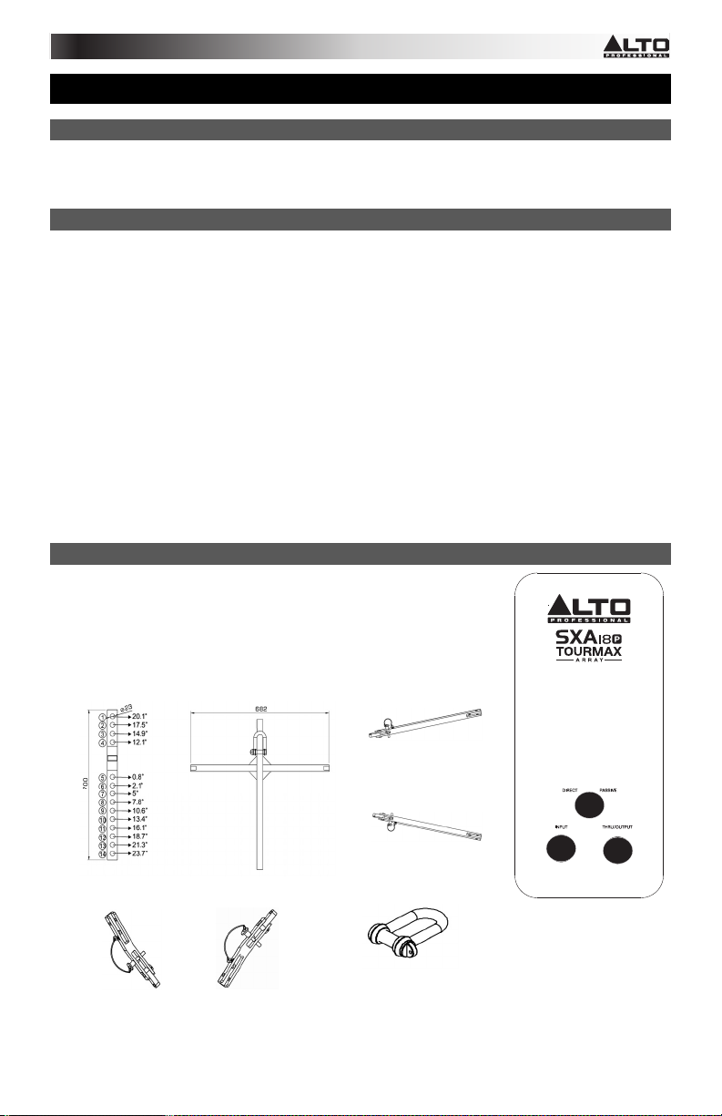
REAR PANEL DIAGRAM
1. Direct/Passive Switch- Sets the operating mode of the speakers. Refer to the
chart on the Specifications page for more details on how this affects the signal
routing
2. Input connector- Connect your Speakon* cable to this input
3. Thru/Output connector- Connect your Speakon cable to this output
LINE ARRAY HARDWARE PARTS
FB-1
SAT-HD-L
SAT-HD-R
* Speakon is a trademark of Neutrik® AG, registered in the U.S. and other countries.
SUB-HD-L
SUB-HD-R
2
SH
1
3
3
Page 4
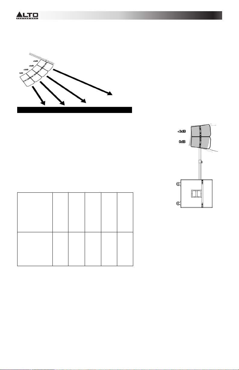
Medium Array Configuration
Below is an example of applying the HFC to four SXA18P’s in an array. In this particular configuration, the
HFC on the top speaker is set at +3 dB, and the bottom speaker 0 dB.
Small Array Configuration
This is an example of the HFC application with two SXA18P’s in a small array,
with the top speaker set at +3 dB and the bottom speaker at 0 dB. Do not stack
more than two SXA18P speakers on the pole.
Be sure to lock the two speaker cabinets with the original hardware.
Array Frame
The following table defines the maximum number of speakers that may be
suspended using the FB-1 array frame. A security design factor is maintained for
the speaker configurations indicated in the table.
Maximum Array Configurations
Maximum
2
3
4
5 6
quantity of
SXA28P in
array
(satellite)
Maximum
1
1
1
0 0
quantity of
SXA18P in
array
Suspension Safety Warning
• Never exceed the maximum recommended speaker cabinet listed on the table.
• Research and understand the local regulation and requirements of the country where you intend to
install the line array. The correct assembly of all associated hardware is required for a safe suspension
system.
• Two point suspension with uniform loading of each lifting location is recommended when using Array
Frame FB-1
4
Page 5

Array Frame Connection
The FB-1 frame is connected to SXA-HD-L and SXA-HD-R with ALTO quick release pins.
LOCKING THE LOUDSPEAKERS TOGETHER
Any time two or more SXA18P and SXA28P’s are arrayed together, they must be mechanically secured to
each other. See the diagram below for details.
DEPLOYING THE SYSTEM IN SUSPENSION & COMPRESSION
Suspension
Compression
5
Page 6

CH3
CH4
CH4
CH3
CH1
CH2
CH2
CH1
BREAKER
AC INPUT
CH3
CH4
CH4
CH3
CH1
CH2
CH2
CH1
BREAKER
AC INPUT
CH3
CH4
CH4
CH3
CH1
CH2
CH2
CH1
BREAKER
AC INPUT
CH3
CH4
CH4
CH3
CH1
CH2
CH2
CH1
CH3
CH4
CH4
CH3
CH1
CH2
CH2
CH1
BREAKER
AC INPUT
CH3
CH4
CH4
CH3
CH1
CH2
CH2
CH1
BREAKER
AC INPUT
CH3
CH4
CH4
CH3
CH1
CH2
CH2
CH1
BREAKER
AC INPUT
CH3
CH4
CH4
CH3
CH1
CH2
CH2
CH1
CONFIGURATIONS
DIRECT / PASSIVE MODES
INPUT
DIRECT
LOW
FREQ
INPUT
PASSIVE
LOW
FREQ
THRU
OUTPUT
HOOK-UP: 12x SXA28P + 8x SXA18P
RIGHT
SXA-R1
SXA-R2
SXA-R3
SXA-R4
SXA-R5
R1
R2
R3
SXA-R6
SXA28P
R5 R4
R6
R8 R7
SXA-R6
SXA-R5
SXA-R1
SXA-R2
SXA-R4
SXA-R3
R12
R11
R4
R10
R9
R1R2R3
AC INPUT
BREAKER
BREAKER
R5
SXA-R4
SXA-R3
SXA-R1 SXA-R2
R4
AC INPUT
AC INPUT
BREAKER
SXA18P
Connector
pack
R4
R4
R1 R2 R3
R1 R2 R3
L4L5
L5
L11 L12
L6L7
L4
L9 L10
L8
CH2
CH1
CH2
CH1
L6
L1
L2 L1
L3
R2 R1
L3 L2
R3
CH2
CH2
CH4
CH2
CH4
CH4
CH1
CH3
CH3
CH4
CH4
CH2
CH1
CH3
CH3
L7
L8
L6
L5
L1
L4
L3
L2
CH4
CH1
CH1
CH3
CH3
CH4
CH4
CH2
CH2
Powered
Amplifiers
CH1
CH1
CH3
CH3
R10
R9
R11
R12
L4
L3
L2
L1
AC INPUT
AC INPUT
BREAKER
AC INPUT
BREAKER
BREAKER
L4
L4
SXA-L6
L3
L2
L1
SXA28P
CH2
CH1
CH2
CH1
L6
CH2
CH2
CH4
CH2
CH4
CH4
CH1
CH3
CH3
CH4
CH4
CH2
CH1
CH3
CH3
L7
L8
CH4
CH1
CH1
CH3
CH3
CH4
CH4
CH2
CH2
CH1
CH1
CH3
CH3
L11
L9
L10
L12
SXA-L4
SXA-L3
SXA-L2
SXA-L1
Powered
Amplifiers
SXA18P
6
Connector
pack
L3
L2
L1
LEFT
SXA-L1
SXA-L2
SXA-L3
SXA-L4
SXA-L5
Page 7

GUÍA DE INICIO RÁPIDO (ESPAÑOL)
CONTENIDO DE LA CAJA
SXA18P
Guía de inicio rápido
Folleto de información sobre la seguridad y la garantía
INSTALACIÓN RÁPIDA
1. Asegúrese de que todos los artículos indicados en CONTENIDO DE LA CAJA estén incluidos en la misma.
2. LEA EL FOLLETO DE INFORMACIÓN SOBRE LA SEGURIDAD Y LA GARANTÍA ANTES DE UTILIZAR EL
PRODUCTO.
3. Estudie el diagrama de conexión incluido en esta guía.
4. Coloque todos los dispositivos en una posición adecuada para su funcionamiento.
5. Asegúrese que todos los dispositivos estén apagados y que todos los atenuadores (faders) y perillas de
ganancia estén en posición “cero".
6. Conecte las salidas de todas las fuentes de sonido a las entradas del amplificador, como se indica en el
diagrama.
7. Conecte las salidas del amplificador a los altavoces.
8. Enchufe todos los dispositivos a un suministro eléctrico apropiado.
9. Encienda todo en el siguiente orden:
• Fuentes de sonido (por ejemplo, micrófonos, giradiscos, reproductores de CD, etc.)
• Mezclador
• Amplificador
• Altavoces
10. Al apagar los equipos, apague los mismos en el siguiente orden:
• Altavoces
• Amplificador
• Mezclador
• Fuentes de sonido
DIAGRAMA DEL PANEL TRASERO DEL SXA 18P
1. Conmutador directo/pasivo - Fija el modo de funcionamiento de los
altavoces. Consulte la tabla de la página de Especificaciones para conocer
más detalles sobre cómo afecta esto al enrutamiento de la señal
2. Conector de entrada - Conecte su cable Speakon* a esta entrada
3. Conector pasante/de salida - Conecte su cable Speakon* a esta salida
PIEZAS DE HARDWARE DEL ARREGLO DE LÍNEA
FB-1
SAT-HD-L
SAT-HD-R
7
SH
SUB-HD-L
SUB-HD-R
1
2
* Speakon es una marca comercial de Neutrik®
AG., registrada en EE.UU. y otros países.
3
Page 8

Configuración de arreglo mediano
Se presenta a continuación un ejemplo de aplicación del HFC a un arreglo de cuatro SXA18. En esta
configuración particular, el HFC que está sobre el altavoz de arriba se ajusta a +3 dB y el del altavoz de
abajo a 0 dB.
Configuración de arreglo pequeño
Éste es un ejemplo de la aplicación del HFC con dos SXA18 en un arreglo
pequeño, con el altavoz de arriba ajustado a +3 dB y el de abajo a 0 dB. No apile
más de dos altavoces SXA18P/ 28P en la columna.
Asegúrese de bloquear los dos gabinetes de altavoces con los elementos de
fijación originales.
Bastidor para arreglos
La tabla siguiente define el número máximo de altavoces que se pueden
suspender usando el altavoz para arreglos FB-1. Se mantiene un factor de
diseño de seguridad para las configuraciones de altavoces indicadas en la tabla.
Configuraciones máximas del arreglo
Cantidad
2
3
4
5 6
máxima de
SXA28P del
arreglo
(satélite)
Cantidad
1
1 0 0
1
máxima de
SXA18P del
arreglo
Advertencia sobre la seguridad de la suspensión
• Nunca exceda el máximo recomendado de gabinetes de altavoces indicado en la tabla.
• Investigue y entienda las reglamentaciones y los requisitos locales del país donde tiene previsto
instalar el arreglo de línea. Para que el sistema de suspensión sea seguro, se requiere el armado
correcto de todos los elementos de fijación asociados.
• Se recomienda la suspensión en dos puntos con carga uniforme de cada ubicación de elevación
cuando se usa el bastidor para arreglos FB-1
8
Page 9

Conexión del bastidor para arreglos
El bastidor FB-1 se conecta al SXA-HD-L y el SXA-HD-R con pasadores de liberación rápida ALTO.
FIJACIÓN DE LOS ALTAVOCES
Toda vez que dos o más SXA18P y SXA28P se colocan juntos en un arreglo, se deben sujetar
mecánicamente entre sí. Consulte los detalles en el diagrama de abajo.
DESPLIEGUE DEL SISTEMA EN SUSPENSIÓN Y COMPRESIÓN
Suspensión
Compresión
9
Page 10

CH3
CH4
CH4
CH3
CH1
CH2
CH2
CH1
BREAKER
AC INPUT
CH3
CH4
CH4
CH3
CH1
CH2
CH2
CH1
BREAKER
AC INPUT
CH3
CH4
CH4
CH3
CH1
CH2
CH2
CH1
BREAKER
AC INPUT
CH3
CH4
CH4
CH3
CH1
CH2
CH2
CH1
CH3
CH4
CH4
CH3
CH1
CH2
CH2
CH1
BREAKER
AC INPUT
CH3
CH4
CH4
CH3
CH1
CH2
CH2
CH1
BREAKER
AC INPUT
CH3
CH4
CH4
CH3
CH1
CH2
CH2
CH1
BREAKER
AC INPUT
CH3
CH4
CH4
CH3
CH1
CH2
CH2
CH1
CONFIGURACIONES
MODOS DIRECTO Y PASIVO
ENTRADAD
DIRECTO
ENTRADAD
BAJA
FREC
PASIVO
BAJA
FREC
PASANTE
SALIDA
CONEXIÓN: 12 SXA28P + 8 SXA18P
LADO
DERECHO
SXA-R1
SXA-R2
SXA-R3
SXA-R4
SXA-R5
R1
R2
R3
SXA-R6
SXA28P
R5 R4
R6
R8 R7
SXA-R6
SXA-R5
SXA-R1
SXA-R2
SXA-R4
SXA-R3
R12
R11
R4
R10
R9
BREAKER
AC INPUT
R1R2R3
AC INPUT
BREAKER
R5
SXA-R4
SXA-R3
SXA-R1 SXA-R2
R4
AC INPUT
BREAKER
SXA18P
LADO
IZQUIERDO
Bloque de
conectores
Bloque de
conectores
SXA-L1
SXA-L2
SXA-L3
R4
R1 R2 R3
L5
L4
L4
L3
L2
L1
SXA-L4
SXA-L6
SXA-L5
R4
R1 R2 R3
L4L5
L11 L12
L6L7
L9 L10
L2 L1
L8
L3
L4
L3
L2
L1
SXA28P
CH2
CH1
CH2
CH1
L6
L1
L3 L2
L1
R2 R1
R3
CH2
CH1
CH2
CH1
CH2
CH2
CH4
CH2
CH4
CH4
CH1
CH3
CH3
CH4
CH4
CH2
CH1
CH3
CH3
L7
L8
L6
L5
L4
L3
L2
BREAKER
CH2
CH4
CH1
CH3
CH4
CH2
CH1
CH3
L6
L7
L8
CH4
CH1
CH1
CH3
CH3
CH4
CH4
CH2
CH2
CH1
CH1
CH3
CH3
R10
R9
R11
R12
L4
L3
L2
L1
AC INPUT
AC INPUT
CH4
CH3
CH4
CH3
AC INPUT
BREAKER
BREAKER
CH2
CH2
CH4
CH4
CH1
CH1
CH3
CH3
CH4
CH4
CH2
CH2
CH1
CH1
CH3
CH3
L9
L11
L10
L12
SXA-L4
SXA-L3
SXA-L2
SXA-L1
SXA18P
Amplificadores
alimentados
Amplificadores
alimentados
10
Page 11

SPECIFICATIONS
POWER SPECIFICATIONS
• Power Rating (Direct Mode): (AES Standard), 3000 W Peak / 1500 W
Program / 750 W Continuous
• Nominal SPL @ 1m: 122dB SPL Continuous (Direct Mode)
• Maximum SPL @ 1m: 125 dB Peak (Direct Mode), 122 dB SPL Continuous
(Direct Mode)
ELECTRICAL SPECIFICATION
• Operating Frequency Range (-10 dB): 37 Hz - 200 Hz
• Frequency Response (-3 dB): 43 Hz - 200 Hz
• Transducers Low: 18” Subwoofer, 4” voice coil high-power ferrite magnet,
weather-resistant cone.
• Crossover modes: Passive / Direct with external selector
• System Sensitivity (1W@ 1 mt): 97 dB SPL (passive configuration)
• Nominal Impedance: 8 Ω (nominal)
• Suspension/Mounting: Single 36 mm pole socket, four integrated points
for line array suspension, two handles, optional casters
GENERAL SPECIFICATIONS
• Enclosure: 18 mm birch plywood, black finish, perforated metal grille, silver
finish
• Input Connector: Speakon NL4-type
• Thru/Output Connector: Speakon NL4-type
DIMENSIONS (WxLxH)
• 24.4" x 24.4" x 27.5" (619.7 mm x 619.7 mm x 698. mm)
WEIGHT
• 114.2 lbs. (51.8 kg.)
11
Page 12

www.altoprofessional.com
MANUAL VERSION 1.2
 Loading...