

Page 1

RAM Initializer (ALTMEM_INIT)
Megafunction User Guide
101 Innovation Drive
San Jose, CA 95134
www.altera.com
Software Version: 8.0
Document Version: 1.0
Document Date: May 2008
Page 2

Copyright © 2008 Altera Corporation. All rights reserved. Altera, The Programmable Solutions Company, the stylized Altera logo, specific device designations, and all other words and logos that are identified as trademarks and/or service marks are, unless noted otherwise, the trademarks and
service marks of Altera Corporation in the U.S. and other countries. All other product or service names are the property of their respective holders. Altera products are protected under numerous U.S. and foreign patents and pending applications, maskwork rights, and copyrights. Altera warrants
performance of its semiconductor products to current specifications in accordance with Altera's standard warranty, but reserves the right to make
changes to any products and services at any time without notice. Altera assumes no responsibility or liability arising out of the application or use of any information, product, or service described herein except as expressly agreed to in writing by Altera
Corporation. Altera customers are advised to obtain the latest version of device specifications before relying on any published information and before placing orders for products or services.
UG-01034-1.0
ii Confidential—Internal Use Only Altera Corporation
RAM Initializer (ALTMEM_INIT) Megafunction User Guide May 2008
Page 3

Contents
About this User Guide ............................................................................. v
Revision History ........................................................................................................................................ v
Referenced Documents ............................................................................................................................. v
How to Contact Altera .............................................................................................................................. v
Typographic Conventions ...................................................................................................................... vi
Chapter 1. About this Megafunction
Device Family Support ......................................................................................................................... 1–1
Introduction ............................................................................................................................................ 1–1
Features ................................................................................................................................................... 1–2
General Description ............................................................................................................................... 1–3
Chapter 2. Getting Started
Software and System Requirements ................................................................................................... 2–1
MegaWizard Plug-In Manager Customization ................................................................................. 2–1
MegaWizard Plug-In Manager Page Descriptions ........................................................................... 2–2
Instantiating Megafunctions in HDL Code or Schematic Designs ................................................. 2–8
Generating a Netlist for EDA Tool Use ......................................................................................... 2–8
Using the Port and Parameter Definitions .................................................................................... 2–9
Identifying a Megafunction after Compilation ................................................................................. 2–9
Simulation ............................................................................................................................................... 2–9
Quartus II Software Simulator ....................................................................................................... 2–9
EDA Simulator ................................................................................................................................ 2–10
Design Example 1: RAM Initialization with Initialization Data File ........................................... 2–10
Design Files ..................................................................................................................................... 2–10
Configuration Settings ................................................................................................................... 2–11
Functional Simulation in the ModelSim-Altera Simulator ...................................................... 2–11
Understanding the Simulation Results ....................................................................................... 2–12
Design Example 2: Memory Initialization with External ROM .................................................... 2–15
Design Files ..................................................................................................................................... 2–15
Configuration Settings ................................................................................................................... 2–16
Functional Simulation in the ModelSim-Altera Simulator ...................................................... 2–16
Understanding the Simulation Results ....................................................................................... 2–17
Conclusion ............................................................................................................................................ 2–19
Chapter 3. Specifications
Ports and Parameters ............................................................................................................................ 3–1
Altera Corporation iii
RAM Initializer (ALTMEM_INIT) Megafunction User Guide
Page 4

Contents
iv Confidential—Internal Use Only Altera Corporation
RAM Initializer (ALTMEM_INIT) Megafunction User Guide
Page 5
About this User Guide
Revision History
Date and Document
Version
May 2008
v1.0
Referenced Documents
How to Contact Altera
The following table shows the revision history for this user guide.
Changes Made Summary of Changes
Initial release. —
This user guide references the following documents:
■ Quartus II Integrated Synthesis chapter in volume 1 of the Quartus II
Handbook
■ Recommended HDL Coding Styles chapter in volume 1 of the Quartus II
Handbook
■ Simulation section in volume 3 of the Quartus II Handbook
■ Synthesis section in volume 1 of the Quartus II Handbook
For the most up-to-date information about Altera® products, refer to the
following table.
Contact (1)
Technical support Website www.altera.com/support
Technical training Website www.altera.com/training
Product literature Website www.altera.com/literature
Non-technical support (General)
(Software Licensing)
Note to table:
(1) You can also contact your local Altera sales office or sales representative.
Contact
Method
Email custrain@altera.com
Email nacomp@altera.com
Email authorization@altera.com
Address
Altera Corporation Confidential—Internal Use Only v
May 2008 RAM Initializer (ALTMEM_INIT) Megafunction User Guide
Page 6

Typographic Conventions
Typographic
This document uses the typographic conventions shown in the following
table.
Conventions
Visual Cue Meaning
Bold Type with Initial
Capital Letters
bold type External timing parameters, directory names, project names, disk drive names,
Italic Type with Initial Capital
Letters
Italic type Internal timing parameters and variables are shown in italic type.
Initial Capital Letters Keyboard keys and menu names are shown with initial capital letters. Examples:
“Subheading Title” References to sections within a document and titles of on-line help topics are
Courier type Signal and port names are shown in lowercase Courier type. Examples: data1,
1., 2., 3., and
a., b., c., etc.
● • Bullets are used in a list of items when the sequence of the items is not important.
■
v The checkmark indicates a procedure that consists of one step only.
1 The hand points to information that requires special attention.
c
w
r The angled arrow indicates you should press the Enter key.
f The feet direct you to more information about a particular topic.
Command names, dialog box titles, checkbox options, and dialog box options are
shown in bold, initial capital letters. Example: Save As dialog box.
filenames, filename extensions, and software utility names are shown in bold
type. Examples: \qdesigns directory, d: drive, chiptrip.gdf file.
Document titles are shown in italic type with initial capital letters.
Example: AN 75: High-Speed Board Design.
Examples: t
Variable names are enclosed in angle brackets (< >) and shown in italic type.
Example: <file name>, <project name>.pof file.
Delete key, the Options menu.
shown in quotation marks. Example: “Typographic Conventions.”
PIA
, n + 1.
tdi, input. Active-low signals are denoted by suffix n, e.g., resetn.
Anything that must be typed exactly as it appears is shown in Courier type. For
example:
actual file, such as a Report File, references to parts of files (e.g., the AHDL
keyword
Courier.
Numbered steps are used in a list of items when the sequence of the items is
important, such as the steps listed in a procedure.
A caution calls attention to a condition or possible situation that can damage or
destroy the product or the user’s work.
A warning calls attention to a condition or possible situation that can cause injury
to the user.
c:\qdesigns\tutorial\chiptrip.gdf. Also, sections of an
SUBDESIGN), as well as logic function names (e.g., TRI) are shown in
vi Confidential—Internal Use Only Altera Corporation
RAM Initializer (ALTMEM_INIT) Megafunction User Guide May 2008
Page 7

Chapter 1. About this
Megafunction
Device Family Support
The RAM Initializer (ALTMEM_INIT) megafunction supports the
following target Altera
■ ACEX
■ APEX™ II
■ APEX 20KC
■ APEX 20KE
■ Arria™ GX
■ Cyclone
■ Cyclone II
■ Cyclone
■ FLEX 10K
■ FLEX
■ FLEX 10KE
■ FLEX 6000
■ HardCopy
■ HardCopy Stratix
■ MAX
■ MAX 3000A
■ MAX 7000AE
■ MAX 7000B
■ MAX 7000S
■ Stratix IV
■ Stratix III
■ Stratix II
■ Stratix II GX
■ Stratix
■ Stratix GX
®
1K
®
®
10KA
®
II
III
®
®
®
device families:
II
®
Introduction
As design complexities increase, the use of vendor-specific intellectual
property (IP) blocks has become a common design methodology. Altera
provides parameterizable megafunctions that are optimized for Altera
device architectures. Using megafunctions instead of coding your own
logic saves valuable design time. Additionally, the Altera-provided
functions may offer more efficient logic synthesis and device
implementation. You can scale the size of the megafunction by setting
parameters.
Altera Corporation Confidential—Internal Use Only 1–1
May 2008 RAM Initializer (ALTMEM_INIT) Megafunction User Guide
Page 8

Features
The HardCopy device family does not support the initialization of a
random-access memory (RAM) during power-up. The ALTMEM_INIT
megafunction addresses this need by providing memory initialization
functions for the HardCopy Stratix and HardCopy II devices. The
megafunction also supports Stratix devices that are migratable to
HardCopy devices, and in general, other Altera devices that come with
RAM.
The ALTMEM_INIT megafunction supports multiple RAMs. You can
add logic to the output data port of the megafunction to fan out to more
than one RAM. For example, if you want to initialize multiple RAMs to
contain all zeros, you can connect the appropriate output ports of the
ALTMEM_INIT megafunction to the RAMs that you want to initialize.
1 In this document, HardCopy devices refer to the
HardCopy Stratix and HardCopy II devices; Stratix devices
refer to the Stratix IV, Stratix III, Stratix II, and Stratix devices.
The ALTMEM_INIT megafunction initializes the RAM of a HardCopy
device with the content of a read-only memory (ROM). The ROM can be
located internally within the megafunction, or externally in an on-chip or
off-chip ROM. During initialization, the megafunction reads the content
of the ROM word-by-word and writes it to the RAM. The RAM can also
be initialized without the ROM, but the content can only be set to all
zeros.
1 Unless specified otherwise, external ROM refers to both on-chip
and off-chip ROM.
Features
The ALTMEM_INIT megafunction provides the following features to
implement memory initialization in HardCopy devices:
■ Support for RAM initialization using the INIT_FILE parameter
■ Support for RAM initialization from an external ROM with fixed
latency
■ Support for RAM initialization from an external ROM with variable
latency
■ Support for RAM initialization to all zeros
■ Status signal to indicate RAM initialization status
These features can be configured easily through the RAM Initializer
®
MegaWizard
Plug-In Manager.
f For more information about the INIT_FILE parameter, refer to
Chapter 3, Specifications.
1–2 Confidential—Internal Use Only Altera Corporation
RAM Initializer (ALTMEM_INIT) Megafunction User Guide May 2008
Page 9

About this Megafunction
General Description
The main function of the ALTMEM_INIT megafunction is to copy the
content of a ROM into the RAM of a HardCopy device. The RAM can be
initialized in two modes—the internal-ROM or external-ROM mode. For
both modes, initialization begins when you assert the init signal.
In the internal-ROM mode, the RAM is initialized with the content of the
ROM in the ALTMEM_INIT megafunction. This mode uses only the
INIT_FILE parameter and does not require any connection to the
datain[] and rom_address[] ports.
In the external-ROM mode, the RAM is initialized from either an on-chip
or off-chip ROM. The datain[] and rom_address[] ports of the
megafunction must be connected to the external ROM. The initialization
process can be automated with a fixed latency by using the
ROM_READ_LATENCY parameter, or configured with a variable latency by
using the PORT_ROM_DATA_READY parameter and the
rom_data_ready control signal.
For the initialization of a RAM from an external ROM with fixed latency,
set the ROM_READ_LATENCY parameter to the number of delay cycles
incurred after the ALTMEM_INIT megafunction initiates a read from the
ROM. For example, if the ROM has both its input and output ports
registered, you can set the clock latency to 2 clock cyles. A fixed latency is
usually used for an external on-chip ROM where you can identify the
number of delay cycles.
For an off-chip ROM, you may not be able to identify the latency, or the
latency may vary for different ROMs. In such cases of variable latency,
you can use the PORT_ROM_DATA_READY parameter and the
rom_data_ready signal to control when to read data into the
megafunction.
The ALTMEM_INIT megafunction can also initialize a RAM without a
ROM, but the RAM content can only be set to all zeros. For such an
initialization, you do not need to use the INIT_FILE parameter or any
ROM ports.
The init_busy signal of the ALTMEM_INIT megafunction reflects the
initialization status. You can use this signal as an active-low signal to
enable the subsequent processes or as an indicator to show that memory
initialization is complete.
Altera Corporation Confidential—Internal Use Only 1–3
May 2008 RAM Initializer (ALTMEM_INIT) Megafunction User Guide
Page 10
General Description
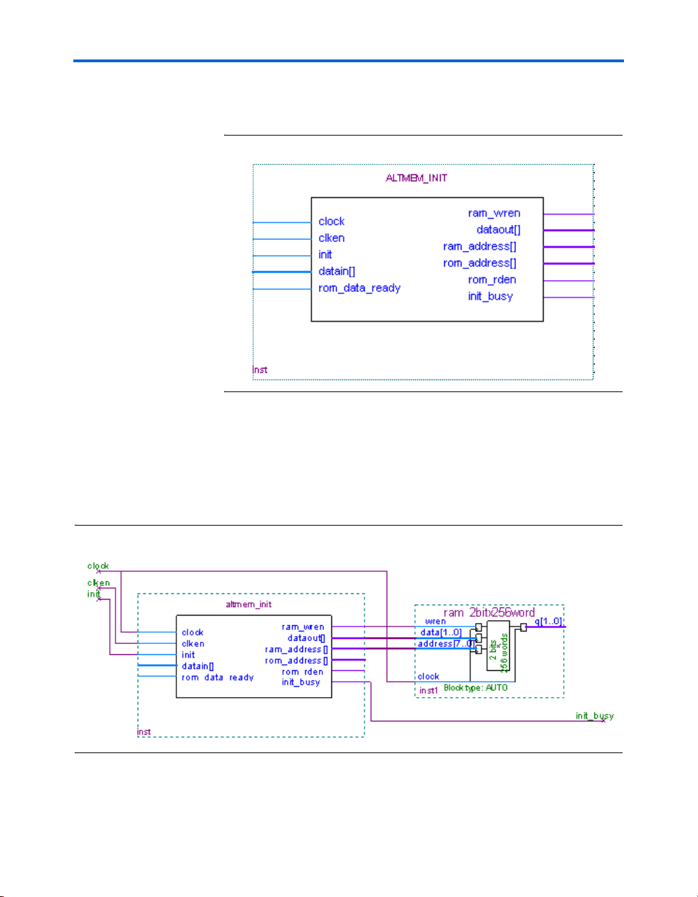
Figure 1–1 shows the block diagram of the input and output ports of the
ALTMEM_INIT megafunction.
Figure 1–1. Input and Output Ports of ALTMEM_INIT Megafunction
Figure 1–2 shows the block connections for the initialization of a
HardCopy device RAM using the INIT_FILE parameter. For this mode,
the ROM resides in the ALTMEM_INIT megafunction.
1 The block connections in Figure 1–2 also apply to RAM
initialization without a ROM.
Figure 1–2. Initializing RAM to All Zeros or with INIT_FILE Parameter
1–4 Confidential—Internal Use Only Altera Corporation
RAM Initializer (ALTMEM_INIT) Megafunction User Guide May 2008
Page 11

About this Megafunction
Figure 1–3 shows the block connections for the initialization of a
HardCopy device RAM in the external-ROM mode. This mode uses an
external on-chip or off-chip ROM.
Figure 1–3. Initializing RAM with External ROM
Altera Corporation Confidential—Internal Use Only 1–5
May 2008 RAM Initializer (ALTMEM_INIT) Megafunction User Guide
Page 12

General Description
1–6 Confidential—Internal Use Only Altera Corporation
RAM Initializer (ALTMEM_INIT) Megafunction User Guide May 2008
Page 13

Chapter 2. Getting Started
Software and System Requirements
MegaWizard Plug-In Manager Customization
The instructions in this section require the following software:
■ Quartus
■ For operating system support information, refer to:
www.altera.com/support/software/os_support/oss-index.html
The MegaWizard® Plug-In Manager creates or modifies design files that
contain custom megafunction variations, which can then be instantiated
in a design file. The MegaWizard Plug-In Manager provides a wizard that
allows you to specify options for the RAM Initializer (ALTMEM_INIT)
megafunction features in your design.
1 In this document, HardCopy
Start the MegaWizard Plug-In Manager in one of the following ways:
■ On the Tools menu, click MegaWizard Plug-In Manager.
■ When working in the Block Editor, on the Edit menu, click Insert
Symbol as Block, or right-click in the Block Editor, point to Insert,
and click Symbol as Block. In the Symbol window, click
MegaWizard Plug-In Manager.
■ Start the stand-alone version of the MegaWizard Plug-In Manager by
typing the following command at the command prompt:
qmegawiz r
®
II software version 8.0 or later
®
devices refer to the
HardCopy Stratix® and HardCopy II devices; Stratix devices
refer to the Stratix IV, Stratix III, Stratix II, and Stratix devices.
Altera Corporation Confidential—Internal Use Only 2–1
May 2008 RAM Initializer (ALTMEM_INIT) Megafunction User Guide
Page 14
MegaWizard Plug-In Manager Page Descriptions
MegaWizard
Plug-In Manager
Page
Descriptions
This section provides descriptions of the options available on the
individual pages of the RAM Initializer wizard.
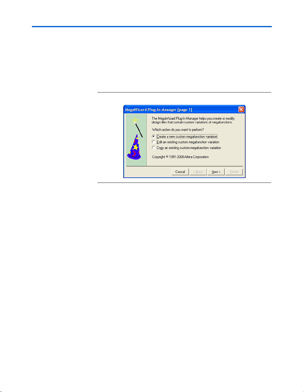
On page 1 of the MegaWizard Plug-In Manager, you can select Create a
new custom megafunction variation, Edit an existing custom
megafunction variation, or Copy an existing custom megafunction
variation (Figure 2–1).
Figure 2–1. MegaWizard Plug-In Manager [page 1]
On page 2a of the MegaWizard Plug-In Manager, specify the
megafunction, device family to use, the type of output file to create, and
the name of the output file (Figure 2–2). Choose AHDL (.tdf), VHDL
(.vhd), or Verilog HDL (.v) as the output file type.
2–2 Confidential—Internal Use Only Altera Corporation
RAM Initializer (ALTMEM_INIT) Megafunction User Guide May 2008
Page 15

Getting Started
Figure 2–2. MegaWizard Plug-In Manager [page 2a]
On page 3 of the MegaWizard Plug-In Manager, select the device family
and random-access memory (RAM) initialization mode. Next, specify the
number of words and data width for the RAM and the read-only memory
(ROM) (Figure 2–3).
1 The message box at the bottom of page 3 of the MegaWizard
Plug-In Manager displays the error messages that appear when
you specify the wrong configuration settings. You can
successfully build the megafunction only after the errors are
fixed.
Altera Corporation Confidential—Internal Use Only 2–3
May 2008 RAM Initializer (ALTMEM_INIT) Megafunction User Guide
Page 16

MegaWizard Plug-In Manager Page Descriptions
Figure 2–3. RAM Initializer MegaWizard Plug-In Manager [page 3 of 5]
2–4 Confidential—Internal Use Only Altera Corporation
RAM Initializer (ALTMEM_INIT) Megafunction User Guide May 2008
Page 17

Getting Started
Table 2–1 shows the options available on page 3 of the RAM Initializer
MegaWizard Plug-In Manager.
Table 2–1. RAM Initializer MegaWizard Plug-In Manager [page 3] Options
Configuration Setting Description
Currently selected device family Select the device family you want to use.
Which RAM initialization mode should be used? If you want to initialize the RAM to all 0’s, select To zero.
If you want to initialize the RAM with the
parameter, select From init data file and specify the file
name.
If you want to initialize the RAM in the external-ROM mode,
select From external ROM.
Turn on Use ROM data ready port if you want to control
the initialization process through the
input port. Turn on Use rom_rden port if the external ROM
supports the read-enable port.
Turn off Use ROM data ready port if you want to automate
the initialization process by specifying the read latency in
clock cycles. After initiating a read from the ROM, the
ALTMEM_INIT megafunction waits for the specified
number of delay cycles before sampling data from the
ROM at the subsequent cycle.(1)
What is the number of words? Specify the number of words (memory depth) for the ROM
What is the data width? Specify the data width for the ROM and the RAM.
Create a
Notes to Ta b l e 2– 1 :
(1) Set the read latency to match the latency, in clock cycles, of the ROM. Set the read latency to 1 clock cycle if only
(2) The number of words for the ALTMEM_INIT megafunction to initialize from the ROM to the RAM.
clken port Turn on this option to create the input port clken, which
the input port of the ROM is registered. Set the read latency to 2 clock cycles if both the input and output ports of
the ROM are registered.
and the RAM.(2)
is used as the clock-enable signal for the megafunction.
INIT_FILE
rom_data_ready
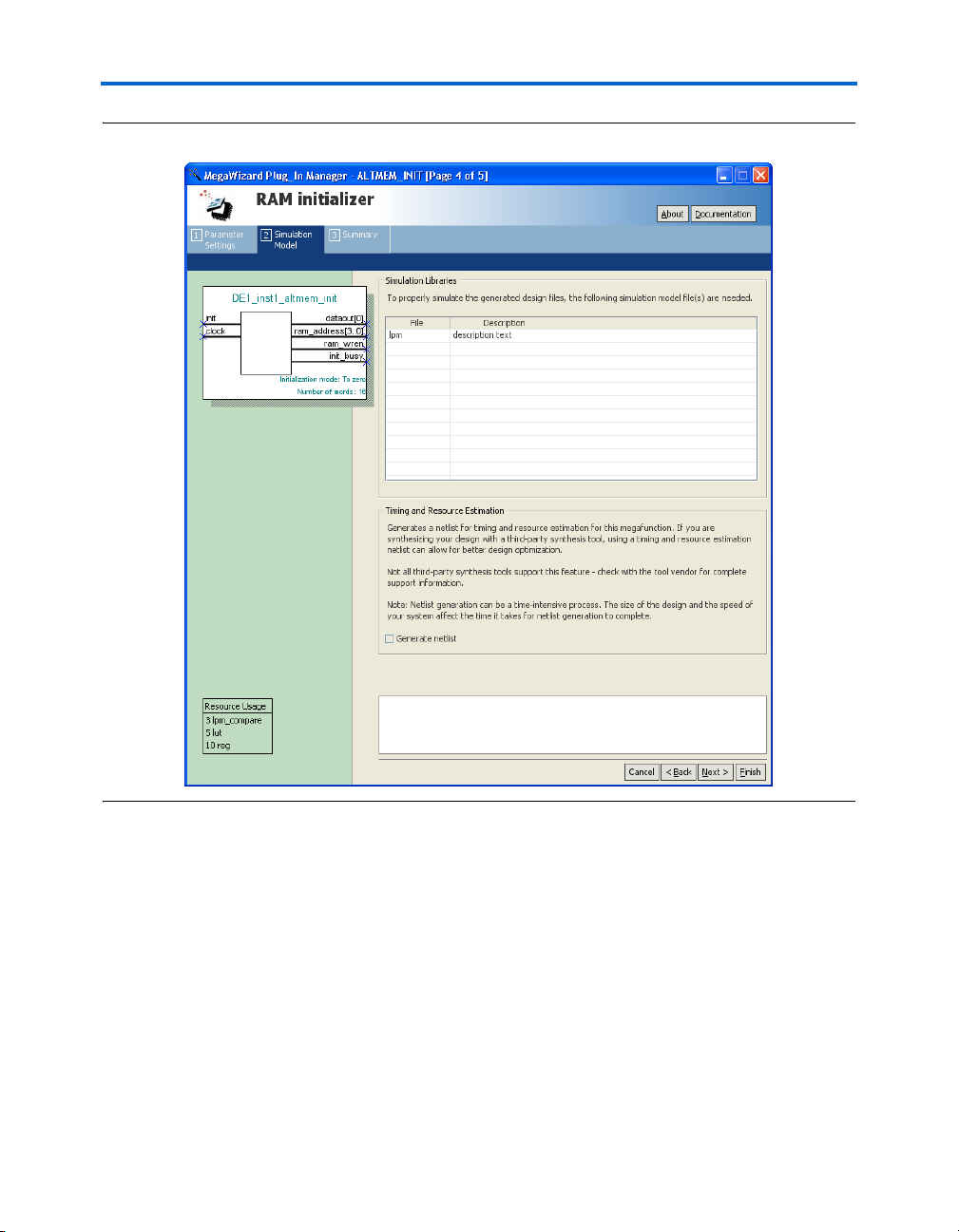
On page 4 of the RAM Initializer MegaWizard Plug-In Manager, you can
choose to generate a netlist for your third-party EDA synthesis tool to
estimate the timing and resource usage of the megafunction (Figure 2–4).
Altera Corporation Confidential—Internal Use Only 2–5
May 2008 RAM Initializer (ALTMEM_INIT) Megafunction User Guide
Page 18
MegaWizard Plug-In Manager Page Descriptions
Figure 2–4. RAM Initializer MegaWizard Plug-In Manager [page 4 of 5]
Page 5 of the RAM Initializer MegaWizard Plug-In Manager displays the
types of files to be generated. The Variation file, which is automatically
generated, contains wrapper code in the language you specified on
page 2a. On page 5 of the RAM Initializer MegaWizard Plug-In Manager,
specify the types of files to be generated. You can choose from the
following types of files:
■ Instantiation template file (<function name>_inst.v)
■ Verilog HDL black-box declaration file (<function name>_bb.v)
■ AHDL Include file (<function name>.inc)
■ VHDL component declaration file (<function name>.cmp)
■ Quartus II symbol file (<function name>.bsf)
■ Quartus II IP Advisor file (<function name>.qip)
2–6 Confidential—Internal Use Only Altera Corporation
RAM Initializer (ALTMEM_INIT) Megafunction User Guide May 2008
Page 19

Getting Started
If you selected Generate netlist on page 4, the file for that netlist is also
available. A gray checkmark indicates a file that is automatically
generated and a green checkmark indicates an optional file (Figure 2–5).
Figure 2–5. RAM Initializer MegaWizard Plug-In Manager [page 5 of 5]
For more information about the ports and parameters for the
ALTMEM_INIT megafunction, refer to Chapter 3, Specifications.
Altera Corporation Confidential—Internal Use Only 2–7
May 2008 RAM Initializer (ALTMEM_INIT) Megafunction User Guide
Page 20

Instantiating Megafunctions in HDL Code or Schematic Designs
Instantiating
Megafunctions
in HDL Code or
Schematic
Designs
f For more information about the wizard-generated files, refer to
When you use the MegaWizard Plug-In Manager to customize and
parameterize a megafunction, it creates a set of output files that allows
you to instantiate the customized function in your design. Depending on
the language you choose in the MegaWizard Plug-In Manager, the wizard
instantiates the megafunction with the correct parameter values and
generates a megafunction variation file (wrapper file) in Verilog HDL (.v),
VHDL (.vhd), or AHDL (.tdf), along with other supporting files.
The MegaWizard Plug-In Manager provides options to create the
following files:
■ A sample instantiation template for the language of the variation file
(_inst.v, _inst.vhd, or _inst.tdf)
■ Component Declaration File (.cmp) that can be used in VHDL
Design Files
■ ADHL Include File (.inc) that can be used in Text Design Files (.tdf)
■ Quartus II Block Symbol File (.bsf) that can be used in schematic
designs
■ Verilog HDL module declaration file that can be used when
instantiating the megafunction as a black box in a third-party
synthesis tool (_bb.v)
Quartus II Help or to the Recommended HDL Coding Styles chapter in
volume 1 of the Quartus II Handbook.
Generating a Netlist for EDA Tool Use
If you use a third-party EDA synthesis tool, you can instantiate the
megafunction variation file as a black box for synthesis. Use the VHDL
component declaration or Verilog HDL module declaration black-box file
to define the function in your synthesis tool, and then include the
megafunction variation file in your Quartus II project.
If you enable the option to generate a synthesis area and timing
estimation netlist in the MegaWizard Plug-In Manager, the wizard
generates an additional netlist file (_syn.v). The netlist file is a
representation of the customized logic used in the Quartus II software.
The file provides the connectivity of the architectural elements in the
megafunction but may not represent true functionality. This information
enables certain third-party synthesis tools to better report area and timing
estimates. In addition, synthesis tools can use the timing information to
focus timing-driven optimizations and improve the quality of results.
f For more information about using megafunctions in your third-party
synthesis tool, refer to the appropriate chapter in the Synthesis section in
volume 1 of the Quartus II Handbook.
2–8 Confidential—Internal Use Only Altera Corporation
RAM Initializer (ALTMEM_INIT) Megafunction User Guide May 2008
Page 21

Getting Started
Using the Port and Parameter Definitions
Instead of using the MegaWizard Plug-In Manager, you can instantiate
the megafunction directly in your Verilog HDL, VHDL, or AHDL code by
calling the megafunction and setting its parameters as you would any
other module, component, or subdesign.
1 Altera strongly recommends that you use the MegaWizard
Plug-In Manager for complex megafunctions. The MegaWizard
Plug-In Manager ensures that you set all megafunction
parameters properly.
For a list of the megafunction ports and parameters, refer to Chapter 3,
Specifications.
Identifying a Megafunction after Compilation
Simulation
During compilation with the Quartus II software, analysis and
elaboration are performed to build the structure of your design. To locate
your megafunction in the Project Navigator window, expand the
compilation hierarchy and find the megafunction by its name.
To search for node names within the megafunction (using the Node
Finder), click Browse in the Look in box and select the megafunction in
the Hierarchy box.
The Quartus II Simulator provides an easy-to-use, integrated solution for
performing simulations. The following sections describe the simulation
options.
Quartus II Software Simulator
With the Quartus II Simulator, you can perform two types of simulations:
functional and timing. A functional simulation enables you to verify the
logical operation of your design without taking into consideration the
timing delays in the FPGA or HardCopy device. This simulation is
performed using only your RTL code. When performing a functional
simulation, add only signals that exist before synthesis. You can find
these signals in the Node Finder by using any of the following Filter
options: Registers: Pre-Synthesis, Design Entry, or Pins. The top-level
ports of megafunctions are found using these three filters.
In contrast, the timing simulation in the Quartus II software verifies the
operation of your design with annotated timing information. This
simulation is performed using the post place-and-route netlist. When
performing a timing simulation, add only signals that exist after
place-and-route. These signals are found with the post-compilation filter
Altera Corporation Confidential—Internal Use Only 2–9
May 2008 RAM Initializer (ALTMEM_INIT) Megafunction User Guide
Page 22

Design Example 1: RAM Initialization with Initialization Data File
of the Node Finder. During synthesis and place-and-route, the names of
RTL signals change. Therefore, it may be difficult to find signals from
your megafunction instantiation in the post-compilation filter.
To preserve the names of your signals during the synthesis and
place-and-route stages, use the synthesis attributes keep or preserve.
These are Verilog HDL and VHDL synthesis attributes that direct analysis
and synthesis to keep a particular wire, register, or node intact. Use these
synthesis attributes to keep a combinational logic node so you can
observe the node during simulation.
f For more information about these attributes, refer to the Quartus II
Integrated Synthesis chapter in volume 1 of the Quartus II Handbook.
EDA Simulator
The Quartus II Handbook chapters describe how to perform functional and
gate-level timing simulations that include the megafunctions, with
details about the files that are needed and the directories where the files
are located.
f Depending on which simulation tool you are using, refer to the
appropriate chapter in the Simulation section in volume 3 of the
Quartus II Handbook.
Design
Example 1: RAM
This design example uses the ALTMEM_INIT megafunction in the
MegaWizard Plug-In Manager to initialize the RAM of a HardCopy II
device with an initialization data file and the INIT_FILE parameter.
Initialization
with
Initialization
Data File
2–10 Confidential—Internal Use Only Altera Corporation
RAM Initializer (ALTMEM_INIT) Megafunction User Guide May 2008
Design Files
To initialize the RAM, you can use the DE1_initfile.mif file, which is a
Memory Initialization File (.mif) that contains the content of the internal
ROM. You can also create your own .mif file using the Quartus II
software. The number of words and data width in the .mif file must be the
same as the corresponding parameter values in the megafunction.
Figure 2–6 shows the content of the initialization data file. In this design
example, the file has 16 words, with each word having a data width of
8bits.
Page 23

Getting Started
Figure 2–6. Content of the Initialization Data File
A top-level design file, DE1_top_internalROM.v, instantiates the
ALTMEM_INIT megafunction and the RAM of the HardCopy II device.
The example design files are available in the User Guides section on the
Literature page of the Altera
Configuration Settings
In the RAM Initializer MegaWizard Plug-In Manager pages, select or
verify the configuration settings shown in Table 2–2. Click Next to
advance from one page to the next.
Table 2–2. Design Example 1: Configuration Settings
MegaWizard Plug-In
Manager Page
3 Currently selected device family HardCopy II
MegaWizard Plug-In Manager Configuration Setting Value
Which RAM initialization mode should be used? From init data file
What is the init data file? DE1_initfile.mif
What is the number of words? 16
What is the data width? 8
Create a
clken port
Functional Simulation in the ModelSim-Altera Simulator
Simulate the design in the ModelSim®-Altera software to generate a
waveform display of the device behavior.
®
website (www.altera.com).
Selected
You should be familiar with the ModelSim-Altera software before trying
out the design example. If you are unfamiliar with the ModelSim-Altera
software, refer to the support page for software products on the Altera
website (www.altera.com). On the support page, there are links to such
topics as installation, usage, and troubleshooting.
Set up and simulate the design in the ModelSim-Altera software by
performing the following steps:
Altera Corporation Confidential—Internal Use Only 2–11
May 2008 RAM Initializer (ALTMEM_INIT) Megafunction User Guide
Page 24

Design Example 1: RAM Initialization with Initialization Data File
1. Unzip the DE1_internalROM.zip file to any working directory on
your PC.
2. Start the ModelSim-Altera software.
3. On the File menu, click Change Directory.
4. Select the folder in which you unzipped the files.
5. Click OK.
6. On the Tools menu, click Execute Macro.
7. Select the DE1_internalROM.do file and click Open. The
DE1_internalROM.do file is a script file for the ModelSim-Altera
software to automate all the necessary settings for the simulation.
8. View the simulation results in the Wave window. Figure 2–7 shows
the expected simulation results in the ModelSim-Altera software.
Figure 2–7. Design Example 1: Simulation Results for RAM Initialization with Initialization Data File
Understanding the Simulation Results
In “Design Example 1: RAM Initialization with Initialization Data File”
on page 2–10, the ALTMEM_INIT megafunction initializes the RAM of a
HardCopy II device with 16 words—each word having a data width of
8 bits—from an internal ROM using the DE1_initfile.mif file.
Figure 2–8 shows the start of initialization after the init signal is
asserted and the appearance of the first initialization value at the output
port of the RAM.
2–12 Confidential—Internal Use Only Altera Corporation
RAM Initializer (ALTMEM_INIT) Megafunction User Guide May 2008
Page 25

Getting Started
Figure 2–8. Design Example 1: Asserting the init Signal
At 2500 ps, the init signal is high, but initialization is unsuccessful
because the clken signal is low. The initialization process can be
activated only when both the clken and init signals are high at the
rising edge of the clock.
At 12,500 ps, both the clken and init signals are high; therefore,
initialization is activated. After initialization is activated, the init_busy
signal is asserted to indicate that initialization is in progress.
1 Consider the time when initialization is activated as the first
rising edge of the clock.
After the initialization is activated, the first value, 0x12, is written into the
RAM at the fifth rising edge of the clock. The value then appears at the
output port of the RAM at the sixth rising edge of the clock. The
ALTMEM_INIT megafunction takes 4 clock cycles to write the first value
into the device RAM—3 clock cycles to generate and 1 clock cycle to write
the value. The device RAM then takes 1 clock cycle to write the value to
its output port, q. In total, the output of the first value is delayed by
5 clock cycles upon assertion of the init signal.
Figure 2–9 shows the delay cycles of the first write process and
subsequent write processes after the init signal is asserted.
Figure 2–9. Design Example 1: Delay Cycles of First Write Process and Subsequent Write Processes
Altera Corporation Confidential—Internal Use Only 2–13
May 2008 RAM Initializer (ALTMEM_INIT) Megafunction User Guide
Page 26

Design Example 1: RAM Initialization with Initialization Data File
In Figure 2–9 , the first value, 0x12, is written into the RAM at the fifth
rising edge of the clock, delayed by 4 clock cycles. The subsequent values,
0x23 and 0x24, are written at the eighth and eleventh rising edges of the
clock, respectively. Both writes are delayed by 3 clock cycles. The rest of
the write processes are also delayed by 3 clock cycles each.
Therefore, if your design or application requires an immediate read from
the RAM without waiting for the initialization process to complete, you
can read the first and subsequent values by taking these delays into
consideration. In this design example, for example, you can read the first
value at the sixth clock cycle after the init signal is asserted, which
corresponds to the seventh rising edge of the clock at 42,500 ps. After that,
you can read the subsequent values at intervals of 3 clock cycles.
Figure 2–10 shows the assertion of the init signal while RAM
initialization is still in progress and the init_busy signal is high.
Figure 2–10. Design Example 1: Assertion of the init Signal While Initialization is Still in Progress
At 92,500 ps, the init_busy signal is high to indicate that the
initialization of the RAM is still in progress. When the init signal is
asserted at this point, the initialization process continues uninterrupted.
Therefore, the assertion of the init signal does not affect the current
initialization process while the init_busy signal is high. The init
signal is asserted only once to begin the initialization; to re-initialize the
RAM, you must wait until the current initialization is complete.
Figure 2–11 shows the RAM initialization process at completion.
2–14 Confidential—Internal Use Only Altera Corporation
RAM Initializer (ALTMEM_INIT) Megafunction User Guide May 2008
Page 27

Getting Started
Figure 2–11. Design Example 1: RAM Initialization at Completion
At 257,500 ps, the ALTMEM_INIT megafunction initiates the last write
cycle to the RAM. The init_busy signal is deasserted during the next
rising edge of the clock at 262,500 ps to indicate the end of initialization.
Design
Example 2:
This design example uses the ALTMEM_INIT megafunction in the
MegaWizard Plug-In Manager to initialize the RAM of a HardCopy II
device with an external on-chip ROM.
Memory
Initialization
with External
ROM
Figure 2–12. Content of the On-Chip ROM
Design Files
The design files for this example are configured for the external-ROM
initialization mode and the latency is fixed with the ROM_READ_LATENCY
parameter. The RAM of the target HardCopy II device is initialized with
the content of an on-chip ROM, located in the device itself.
A top-level design file, DE2_top_externalROM.v, instantiates the on-chip
ROM, the ALTMEM_INIT megafunction, and the RAM of the
HardCopy II device.
Figure 2–12 shows the content of the on-chip ROM. In this design
example, the ROM has 16 words, with each word having a data width of
8 bits. The number of words and data width in the ROM are the same as
the corresponding parameter values in the megafunction.
Altera Corporation Confidential—Internal Use Only 2–15
May 2008 RAM Initializer (ALTMEM_INIT) Megafunction User Guide
Page 28

Design Example 2: Memory Initialization with External ROM
The example design files are available in the User Guides section on the
Literature page of the Altera website (www.altera.com).
Configuration Settings
In the RAM Initializer MegaWizard Plug-In Manager pages, select or
verify the configuration settings shown in Table 2–3. Click Next to
advance from one page to the next.
Table 2–3. Design Example 2: Configuration Settings
MegaWizard Plug-In
Manager Page
3 Currently selected device family HardCopy II
MegaWizard Plug-In Manager Configuration Setting Value
Which RAM initialization mode should be used? From external ROM
What is the read latency? 2
What is the number of words? 16
What is the data width? 8
Create a
clken port
Selected
Functional Simulation in the ModelSim-Altera Simulator
Simulate the design in the ModelSim-Altera software to generate a
waveform display of the device behavior.
You should be familiar with the ModelSim-Altera software before trying
out the design example. If you are unfamiliar with the ModelSim-Altera
software, refer to the support page for software products on the Altera
website (www.altera.com). On the support page, there are links to such
topics as installation, usage, and troubleshooting.
Set up and simulate the design in the ModelSim-Altera software by
performing the following steps:
1. Unzip the DE2_externalROM.zip file to any working directory on
your PC.
2. Start the ModelSim-Altera software.
3. On the File menu, click Change Directory.
4. Select the folder in which you unzipped the files.
5. Click OK.
2–16 Confidential—Internal Use Only Altera Corporation
RAM Initializer (ALTMEM_INIT) Megafunction User Guide May 2008
Page 29

Getting Started
6. On the Tools menu, click Execute Macro.
7. Select the DE2_externalROM.do file and click Open. The
DE2_externalROM.do file is a script file for the ModelSim-Altera
software to automate all the necessary settings for the simulation.
8. View the simulation results in the Wave window. Figure 2–13 shows
the expected simulation results in the ModelSim-Altera software.
Figure 2–13. Design Example 2: Simulation Results for RAM Initialization with External ROM
Understanding the Simulation Results
In “Design Example 2: Memory Initialization with External ROM” on
page 2–15, the ALTMEM_INIT megafunction initializes the RAM of a
HardCopy II device with 16 words—each word having a data width of
8 bits—from an external on-chip ROM.
Figure 2–14 shows the start of initialization after the init signal is
asserted and the appearance of the first initialization value at the output
port of the RAM.
Figure 2–14. Design Example 2: Asserting the init Signal
At 7500 ps, initialization is activated and the init_busy signal asserted
to indicate that the initialization is in progress.
1 Consider the time when initialization is activated as the first
rising edge of the clock.
Altera Corporation Confidential—Internal Use Only 2–17
May 2008 RAM Initializer (ALTMEM_INIT) Megafunction User Guide
Page 30

Design Example 2: Memory Initialization with External ROM
At the second rising edge of the clock at 12,500 ps, the ALTMEM_INIT
megafunction initiates a read from the ROM. Both the address input port
and data output port of the external on-chip ROM are registered;
therefore, the value of the ROM_READ_LATENCY parameter is set to 2.
With this setting, the ALTMEM_INIT megafunction waits 2 clock cycles,
from 12,500 ps to 22,500 ps, before sampling data at the next rising edge
of the clock at 27,500 ps.
1 If the ROM does not have any registered output ports, set the
ROM_READ_LATENCY parameter to 1.
As both the input and output ports of the RAM are also registered, there
is a delay of another 2 clock cycles before the value appears at the output
port of the RAM at 37,500 ps.
In total, upon assertion of the init signal, the first value is delayed by
6 clock cycles before showing up at the output port of the RAM.
Figure 2–15 shows the delay cycles of the first value and subsequent
values that appear at the RAM output port after the init signal is
asserted.
Figure 2–15. Design Example 2: Delay Cycles of First Value and Subsequent Values at the RAM Output Port
In Figure 2–15 , the RAM sends the first value, 0x11, to its output port
after 6 clock cycles. The subsequent values, 0x22 and 0x33, are delayed by
4 clock cycles—2 clock cycles for the ROM read latency and another
2 clock cycles for the value to appear at the output port of the RAM.
Therefore, if your design or application needs to read from the RAM
without waiting for the initialization process to complete, you can read
the first and subsequent values by taking these delays into consideration.
In this design example, for example, you can read the first value at the
seventh clock cycle after the init signal is asserted. After that, you can
read the subsequent values at intervals of 4 clock cycles.
2–18 Confidential—Internal Use Only Altera Corporation
RAM Initializer (ALTMEM_INIT) Megafunction User Guide May 2008
Page 31

Getting Started
Figure 2–15 also shows that the assertion of the init signal does not
affect the current initialization process while the init_busy signal is
high. The init signal is asserted only once to begin the initialization; to
re-initialize the RAM, you must wait until the current initialization is
complete.
Figure 2–16 shows the RAM initialization process at completion.
Figure 2–16. Design Example 2: RAM Initialization at Completion
At 337,500 ps, the last value, 0x1f, appears at the output port of the RAM.
The init_busy signal is deasserted to indicate the end of initialization.
1 If the external ROM has both its input and output ports
registered, and the ROM_READ_LATENCY is set to 1, the last
initialization data is not written to the RAM.
Conclusion
Altera Corporation Confidential—Internal Use Only 2–19
May 2008 RAM Initializer (ALTMEM_INIT) Megafunction User Guide
The ALTMEM_INIT megafunction is designed specifically to support the
RAM initialization in HardCopy devices and Stratix devices that are
migratable to HardCopy devices. You can also use it for other Altera
devices that come with RAM.
The megafunction offers different initialization modes with either an
initialization data file or an external ROM, providing you with the
flexibility to choose a mode that suits your application. You can also select
the appropriate latency mode to control the initialization process
according to your design specifications.
Page 32

Conclusion
2–20 Confidential—Internal Use Only Altera Corporation
RAM Initializer (ALTMEM_INIT) Megafunction User Guide May 2008
Page 33

Chapter 3. Specifications
Ports and Parameters
The Quartus®II software provides the RAM Initializer (ALTMEM_INIT)
megafunction to initialize the random-access memory (RAM) of a device
with the content of a read-only memory (ROM). The ROM can be located
internally within the megafunction, or externally in an on-chip or off-chip
ROM. This chapter describes the ports and parameters of the
ALTMEM_INIT megafunction. These ports and parameters are available
to customize the ALTMEM_INIT megafunction according to your
application.
®
1 In this document, HardCopy
HardCopy Stratix® and HardCopy II devices; Stratix devices
refer to the Stratix IV, Stratix III, Stratix II, and Stratix devices.
1 Unless specified otherwise, external ROM refers to both on-chip
and off-chip ROM.
The parameter details are only relevant for users who bypass the
MegaWizard
directly parameterized instantiation in their design. The details of these
parameters are hidden from the user of the MegaWizard Plug-In Manager
interface.
®
Plug-In Manager interface and use the megafunction as a
devices refer to the
f Refer to the latest version of the Quartus II Help for the most current
information on the ports and parameters for this megafunction.
Figure 3–1 shows the input and output ports for the ALTMEM_INIT
megafunction.
Altera Corporation Confidential—Internal Use Only 3–1
May 2008 RAM Initializer (ALTMEM_INIT) Megafunction User Guide
Page 34

Ports and Parameters
Figure 3–1. Input and Output Ports of the ALTMEM_INIT Megafunction
Table 3–1 shows the input ports, Table 3–2 shows the output ports, and
Table 3–3 shows the parameters for the ALTMEM_INIT megafunction.
Table 3–1. ALTMEM_INIT Megafunction Input Ports
Port Name Required Description Comments
clock
clken
datain[]
init
rom_data_ready
Yes Write clock for RAM. Read clock for
ROM.
No Clock enable port. Values are 0 (disabled) and 1
(enabled). If omitted, the default
value is 1.
No Data input from external ROM. Input port [(width–1)..0] wide. This
port is applicable in the
external-ROM mode only.
Yes When asserted, this signal directs
the megafunction to begin initializing
from ROM.
No Input port for external-ROM mode. When the
—
—
PORT_ROM_DATA_READY
parameter value is set to
PORT_USED, the
rom_data_ready port is used in
the external-ROM mode. Assert this
signal for each word of data when the
ALTMEM_INIT megafunction is
ready to read the data.
3–2 Confidential—Internal Use Only Altera Corporation
RAM Initializer (ALTMEM_INIT) Megafunction User Guide May 2008
Page 35

Specifications
Table 3–2 lists the output ports of the ALTMEM_INIT megafunction.
Table 3–2. ALTMEM_INIT Megafunction Output Ports
Port Name Required Description Comments
dataout[]
Yes Data sent to external RAM. Output port [(width–1)..0] wide. The
value of the
corresponds to the data at the
address specified by the
ram_address port.
init_busy
ram_wren
ram_address[]
rom_address[]
rom_rden
Yes Indicates that the RAM initialization
from ROM is in progress.
Yes Write-enable signal to RAM. When asserted, the data that is sent
Yes RAM address. —
No ROM address that connects to the
external ROM.
No Read-enable signal that connects to
the external ROM.
init_busy signal remains
The
active throughout the initialization
process, and returns to an inactive
state when initialization is complete.
from the
This port is applicable in the
external-ROM mode only. When this
port is in use, connect it to the
address input port of the external
ROM.
This port is applicable in the
external-ROM mode only. When
asserted, the ALTMEM_INIT
megafunction generates valid values
for the
dataout port is valid.
rom_address port.
dataout port
Table 3–3 lists the parameters for the ALTMEM_INIT megafunction.
Table 3–3. ALTMEM_INIT Megafunction Parameters (Part 1 of 2)
Parameter Name Type Required Description
INIT_FILE
String No Specifies the name of the initialization file. If the
INIT_FILE parameter is specified, the
INIT_TO_ZERO parameter value is overridden and
initialization from internal ROM is performed. If the
INIT_FILE and INIT_TO_ZERO parameter values are
not specified, initialization from an external ROM address
is performed. You must connect the appropriate ports
when initialization is from an external ROM address.
INIT_TO_ZERO
String No Specifies whether the RAM must be initialized to contain
all 0’s. The INIT_FILE parameter value takes precedence
over the INIT_TO_ZERO parameter value. Values are
YES and NO. If omitted, the default is NO.
Altera Corporation Confidential—Internal Use Only 3–3
May 2008 RAM Initializer (ALTMEM_INIT) Megafunction User Guide
Page 36

Ports and Parameters
Table 3–3. ALTMEM_INIT Megafunction Parameters (Part 2 of 2)
Parameter Name Type Required Description
NUMWORDS
ROM_READ_LATENCY
Integer Yes Number of words stored in the ROM and the RAM.
Integer No Specifies the number of cycles to wait after the
ALTMEM_INIT megafunction sends a read address to the
ROM to initialize a read. The value of the
ROM_READ_LATENCY parameter must reflect the
latency in clock cycles induced by the registers in the
external ROM. For example, if the ROM has both its input
and output ports registered, set this parameter to 2. This
parameter is valid only in the external-ROM mode.
PORT_ROM_DATA_READY
WIDTHAD
WIDTH
String No
Integer Yes Width of the ROM and the RAM.
Integer Yes Data width of the ROM and the RAM.
Specifies whether the
Values are
the default value is
When the ALTMEM_INIT megafunction is in the
external-ROM mode and the
port is used, set the
parameter to
PORT_USED and PORT_UNUSED. If omitted,
PORT_USED.
rom_data_ready port is used.
PORT_UNUSED.
rom_data_ready input
PORT_ROM_DATA_READY
3–4 Confidential—Internal Use Only Altera Corporation
RAM Initializer (ALTMEM_INIT) Megafunction User Guide May 2008
 Loading...