

Page 1

2013.11.29
www.altera.com
101 Innovation Drive, San Jose, CA 95134
Altera OCT Megafunction User Guide
ug-altera_oct
Subscribe
Feedback
Altera On-Chip Termination (Altera OCT) allows you to dynamically calibrate I/O with reference to an
external resistor. The Altera OCT megafunction improves signal integrity, reduces board space and is
necessary for communicating with external devices such as memory interfaces.
The Altera OCT megafunction is available for Arria®10 devices only. For Arria V, Cyclone®V, and Stratix
V devices, follow the steps in Migrating Your ALTOCT Megafunction on page 1 to migrate your
megafunction.
Related Information
• Introduction to Megafunction IP Cores
• Dynamic Calibrated On-Chip Termination (ALTOCT) Megafunction User Guide
IP Migration Flow for Arria V, Cyclone V, and Stratix V Devices
The IP migration flow allows you to migrate the ALTOCT megafunction of Arria V, Cyclone V, and Stratix
V devices to the Altera OCT megafunction of Arria 10 devices.
The IP migration flow configures the Altera OCT megafunction to match the settings of the ALTOCT
megafunction, allowing you to regenerate the megafunction.
®
Note:
This megafunction only support the IP migration flow in single OCT calibration mode. If you are
using double or POD calibration mode, you do not need to migrate the megafunction.
Migrating Your ALTOCT Megafunction
To migrate your ALTOCT megafunction, follow these steps:
1. Open your ALTOCT megafunction in the MegaWizard Plug-In Manager.
2. In the Currently selected device family, select Arria 10.
3. Click Finish to open the Altera OCT megafunction in the MegaWizard Plug-In Manager. The MegaWizard
Plug-In Manager configures the Altera OCT megafunction settings similar to the ALTOCT megafunction
settings.
4. If there are any incompatible settings between the two, select new supported settings.
5. Click Finish to regenerate the megafunction.
6. Replace your ALTOCT megafunction instantiation in RTL with the Altera OCT megafunction.
Note:
©
2013 Altera Corporation. All rights reserved. ALTERA, ARRIA, CYCLONE, HARDCOPY, MAX, MEGACORE, NIOS, QUARTUS and STRATIX
words and logos are trademarks of Altera Corporation and registered in the U.S. Patent and Trademark Office and in other countries. All other words
and logos identified as trademarks or service marks are the property of their respective holders as described at www.altera.com/common/legal.html.
Altera warrants performance of its semiconductor products to current specifications in accordance with Altera's standard warranty, but reserves the
right to make changes to any products and services at any time without notice. Altera assumes no responsibility or liability arising out of the application
or use of any information, product, or service described herein except as expressly agreed to in writing by Altera. Altera customers are advised to
obtain the latest version of device specifications before relying on any published information and before placing orders for products or services.
The Altera OCT megafunction port names may not match the ALTOCT megafunction port names,
so simply changing the megafunction name in the instantiation is not sufficient.
ISO
9001:2008
Registered
Page 2

2
Parameter Settings
Parameter Settings
This section describes the Altera OCT megafunction parameter settings. You can parameterize the
megafunction using the MegaWizard Plug-In Manager.
Table 1: Altera OCT MegaWizard Plug-In Manager Page Options and Description
Plug-in Man-
ager Page
ug-altera_oct
2013.11.29
DescriptionConfiguration SettingMegaWizard
2a
Which action do you want to perform?1
Which device family will you be using?
Which type of output file do you want to create?
Return to this page for another create operation
Calibration mode3
Select from the following options:
• Create a new custom megafunction
variation
• Edit an existing custom megafunction
variation
• Copy an existing custom megafunction
variation
Select Altera OCT from the I/O category.Select a megafunction from the list below
Specify the device family that you want to
use.
Choose Verilog HDL (.v) as the output file
type.
Specify the name of the output file.What name do you want for the output file?
Turn on this option if you want to return
to this page to create multiple
megafunctions.
Defines the OCT calibration mode. Select
from the following options:
Altera Corporation
• Single: For a given voltage, the OCT
block can generate calibration code only
for a single pair of series/parallel
termination values.
• Double: For a given voltage, the OCT
block can generate calibration code for
up to two pairs of series/parallel
termination values.
• POD: Configures the OCT block to
generate calibration code specific for
pseudo-open drain (POD) I/O
standards.
Altera OCT Megafunction User Guide
Feedback
Page 3
OCT Block OCT Logic
rzqin
Altera OCT
ug-altera_oct
2013.11.29
Features
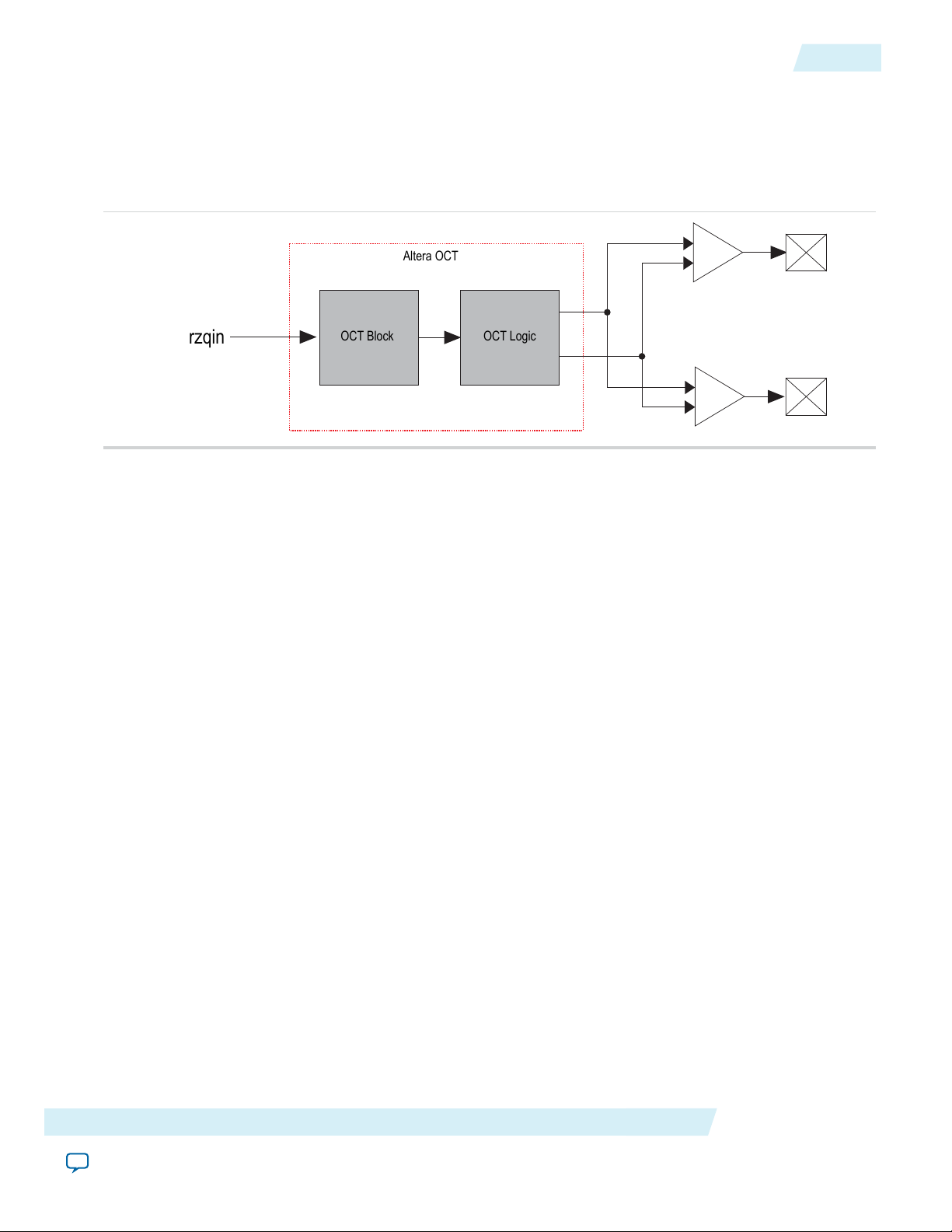
The following figure shows the top-level diagram of the Altera OCT megafunction.
Figure 1: Altera OCT Megafunction Top-Level Diagram
The Altera OCT megafunction provides the following features:
Features
3
• RZQ pin—Dual-purpose pin. When used with OCT, the pin connects to an external reference resistor
to calculate the calibration codes to implement the required impedance.
• OCT block—Generates and sends calibration code words to the I/O buffer blocks.
• OCT logic—Receives the calibration code words serially from the OCT block and sends the calibration
code words in parallel to the buffers.
RZQ Pin
Each OCT block has one RZQ pin. RZQ pins are dual-purpose, which means that if the pins are not connected
to the OCT block, you can use the pins as regular I/O pins. Calibrated pins must have the same VCCIO as
the OCT block and the RZQ pin. Calibrated pins connected to the same OCT block must have the same
series and parallel termination values. You can apply location constraints on the RZQ pins to determine the
placement of the OCT block because the RZQ pin can only be connected to its corresponding OCT block.
OCT Block
The OCT block is a component that generates calibration codes to terminate the I/Os. When calibrating,
the OCT matches the impedance seen on the external resistor through the rzqin port. Then, the OCT
block generates two 16-bit calibration code words; one word calibrates the series termination while the other
calibrates the parallel termination. A dedicated bus serially sends the words to the OCT logic.
OCT Logic
The following figure shows the internals of an OCT logic.
Altera OCT Megafunction User Guide
Feedback
Altera Corporation
Page 4

I/O Block
OCT Logic Block
Serial to
Parallel Shift
Logic
I/O Block
ser_data
clk
0
10
enser[11:0]
0 1
Clock
R
R
R
R
USRMODE
S2PLOAD#
serial_load_en
S2PLOAD
I/O 1 I/O 2
parallelterminationcontrol
seriesterminationcontrol
IOCSR
16
16
4
Functional Description
Figure 2: OCT Logic
ug-altera_oct
2013.11.29
The OCT block serially sends the calibration code words to the OCT logic through the ser_data ports.
The enser signal specifies which OCT block to read the calibration code words from when triggered. The
calibration code words are then buffered into the serial-to-parallel shift logic. Then, the Altera OCT
megafunction asserts the S2PLOAD signal to send the calibration code words in parallel to the I/O buffers.
The calibration code words either activate or deactivate the transistors in the I/O block which will emulate
series or parallel resistance to match the impedance.
Functional Description
To meet DDR memory specification, Arria 10 devices support on-chip series termination (RSOCT) and
on-chip parallel termination (RTOCT) for single-ended I/O standards. OCT can be supported on any I/O
bank. VCCIO must be compatible for all I/Os in a given bank.
An Arria 10 device consists of one OCT block in each x48 I/O tile. Each OCT block requires an external
240Ω reference resistor associated with it through an RZQ pin. An RZQ pin shares the same VCCIO supply
with the I/O bank where it is located. An RZQ pin is a dual function I/O pin that you can use as a regular
I/O if OCT calibration is not used. When used for OCT calibration, the RZQ pin connects the OCT block
to ground through an external 240Ω resistor.
The following figures show how OCTs are connected in a single I/O column (in a daisy chain). An OCT can
calibrate an I/O belonging to any tile, as long as the tile is in the same column and meets the voltage
requirements. Because there are no connections between columns, OCT can only be shared if the pins belong
to the same I/O column of the OCT.
Altera Corporation
Altera OCT Megafunction User Guide
Feedback
Page 5

OCT1
ser_data*
OCT2
ser_data*
OCT0
ser_data*
00
01
1x
00
01
1x
00
01
1x
Sel[1]
Sel[0]
Sel[0]
Sel[1]
Sel[0]
Sel[1]
enser
Sel[1]
Enser_top
enser
Sel[1]
enser
Sel[1]
Sel[0]
Sel[0]
Sel[0]
Enser_top
Enser_top
ug-altera_oct
2013.11.29
Figure 3: Altera OCT Tile-to-Tile Connections
Functional Description
5
Figure 4: Column in Pin Planner
Altera OCT Megafunction User Guide
Feedback
Altera Corporation
Page 6

Altera OCT
To I/O Buffers
To I/O Buffers
Series
Termination
Parallel
Termination
RZQ PAD
6
Interfaces
Interfaces
The Altera OCT megafunction has two main interfaces:
• An input interface directly connected from the FPGA RZQ pad.
• Two 16-bit words output which will connect to I/O buffers.
Figure 5: Altera OCT Interfaces
The following table lists the signals for the interfaces.
Table 2: Signals
ug-altera_oct
2013.11.29
rzqin
series_termination[15:0]
parallel_termination[15:0]
DescriptionSignal Name
Input connection from RZQ pad to the OCT block. RZQ
pad is connected to an external resistance.
OCT uses impedance connected to the rzqin port as a
reference to generate the calibration code.
Output connection from the Altera OCT megafunction to
the I/O buffers.
This is a 16-bit calibration code word which will terminate
an output signal and the I/O buffer.
You must connect the series_termination port to
the seriesterminationcontrol port in the input
or output buffer.
Output connection from the Altera OCT megafunction to
the I/O buffers.
This is a 16-bit calibration code word which will terminate
an input signal and the I/O buffer.
You must connect the parallel_termination port
to the parallelterminationcontrol port in the
input or output buffer.
Altera Corporation
Altera OCT Megafunction User Guide
Feedback
Page 7

ug-altera_oct
2013.11.29
Table 3: Termination Interface Signals
QSF Assignments
DescriptionDirectionSignal Name
7
QSF Assignments
Arria 10 devices has the following termination related Quartus II Settings File (.qsf) assignments:
• INPUT_TERMINATION
• OUTPUT_TERMINATION
• TERMINATION_CONTROL_BLOCK
• RZQ_GROUP
The following table lists the details of each assignment:
Table 4: QSF Assignments
Inputseriesterminationcontrol
16 bit input port. Receives impedance calibration code for
output termination. Source can only be
seriesterminationcontrol port from the Altera
OCT megafunction.
Inputparallelterminationcontrol
16 bit input port. Receives impedance calibration code for
input termination. Source can only be
parallelterminationcontrol port from the
Altera OCT megafunction.
INPUT_TERMINATION
OUTPUT_TERMINATION
DetailsQSF Assignment
The input/output termination assignment specifies
the termination value in ohm on the pin in
question.
Example
set_instance_assignment -name
INPUT_TERMINATION <value> -to
<pin name>
set_instance_assignment -name
OUTPUT_TERMINATION <value> -to
<pin name>
Altera OCT Megafunction User Guide
Feedback
Altera Corporation
Page 8

8
QSF Assignments
DetailsQSF Assignment
ug-altera_oct
2013.11.29
INPUT_TERMINATION
OUTPUT_TERMINATION
TERMINATION_CONTROL_BLOCK
To enable the series/parallel termination ports,
include these assignments which will specify the
series and parallel termination values for the pins.
Make sure to connect the seriesterminationcontrol
and parallelterminationcontrol ports from the
Altera OCT megafunction to the Altera GPIO
megafunction.
Example
set_instance_assignment -name
INPUT_TERMINATION "PARALLEL
<VALUE> OHM WITH CALIBRATION"
-to <pin>
set_instance_assignment -name
OUTPUT_TERMINATION "SERIES
<VALUE> OHM WITH CALIBRATION"
-to <pin>
Directs the Fitter to make the proper connection
from the desired OCT block to the specified pins.
RZQ_GROUP
Example
set_instance_assignment -name
TERMINATION_CONTROL_BLOCK
<desired OCT BLK> -to <pin
name>
This assignment is supported in Arria 10 devices
only. This assignment creates an Altera OCT
megafunction without modifying the RTL.
The Fitter searches for the rzq pin name in the
netlist. If the pin does not exist, the Fitter creates
the pin name along with the Altera OCT
megafunction and its corresponding connections.
This allows you to create a group of pins to be
calibrated by an existing or non-existing OCT and
the Fitter ensures the legality of the design.
Example
set_instance_assignment -name
RZQ_GROUP <rzq pin name> -to
<pin name>
Altera Corporation
Altera OCT Megafunction User Guide
Feedback
Page 9

ug-altera_oct
2013.11.29
Design Example
9
Termination can exist on input and output buffers and sometimes simultaneously.
There are two methods to associate pin groups with an OCT block:
• Use a .qsf assignment to indicate which pin (bus) is associated with which an OCT block. You can either
use the TERMINATION_CONTROL_BLOCK assignment, which will associate a pin with an OCT
instantiated in the RTL, or use the RZQ_GROUP assignment, which will associate the pin with a newly
created OCT without modifying the RTL.
• Instantiate the I/O buffer primitives at the top level and connect them to the appropriate OCT blocks.
Note:
All I/O banks with the same VCCIO can share one OCT block, even if that particular I/O bank
has its own OCT block. You can connect any number of I/O pins that support calibrated
termination to an OCT block. Ensure that you connect I/Os with compatible configuration to an
OCT block. You must also ensure that the OCT block and its corresponding I/Os have the same
VCCIO and series/parallel termination values. Then, the Fitter places the I/Os and OCT block in
the same column. The Quartus®II software generates warning messages if there is no pin connected
to the block.
Design Example
The Altera OCT megafunction can generate a design example that matches the same configuration chosen
for the megafunction. The design example is a simple design that does not target any specific application;
however you can use the design example as a reference on how to instantiate the megafunction.
The .qsys files are for internal use during example design generation only. You cannot edit the files.Note:
The Altera OCT megafunction does not support VHDL generation.Note:
Generating Design Example
During generation, the Generation dialog box displays the option to generate a design example. Turn on
the Generate Example Design option.
The software generates the <instance>_example_design directory along with the megafunction, where
<instance> is the name of your megafunction.
The <instance>_example_design directory contains the - make_qii_design.tcl TCL scripts.
Generating Quartus Design Example
The make_qii_design.tcl generates a synthesizable design example along with a Quartus project,
ready for compilation.
To generate synthesizable design example, run the following script at the end of megafunction generation:
quartus_sh -t make_qii_design.tcl
To specify an exact device to use, run the following script:
quartus_sh -t make_qii_design.tcl [device_name]
Altera OCT Megafunction User Guide
Feedback
Altera Corporation
Page 10

10
Document Revision History
This script generates a qii directory containing a project called ed_synth.qpf. You can open and compile
this project with the Quartus II software.
Document Revision History
The following table lists the revision history for this document.
Table 5: Document Revision History
ug-altera_oct
2013.11.29
ChangesVersionDate
Initial release.2013.11.29November, 2013
Altera Corporation
Altera OCT Megafunction User Guide
Feedback
 Loading...