

Page 1

Low Latency Ethernet 10G MAC
User Guide
Last updated for Altera Complete Design Suite: 15.0
Subscribe
Send Feedback
UG-01144
2015.05.04
101 Innovation Drive
San Jose, CA 95134
www.altera.com
Page 2

TOC-2
Low Latency Ethernet 10G MAC User Guide
Contents
About LL Ethernet 10G MAC............................................................................. 1-1
Getting Started with LL Ethernet 10G MAC...................................................... 2-1
Features......................................................................................................................................................... 1-2
Release Information.....................................................................................................................................1-3
Device Family Support................................................................................................................................1-3
Definition: Device Support Level...................................................................................................1-4
Performance and Resource Utilization.....................................................................................................1-4
Resource Utilization........................................................................................................................ 1-4
TX and RX Latency..........................................................................................................................1-5
Introduction to Altera IP Cores.................................................................................................................2-1
Installing and Licensing IP Cores..............................................................................................................2-2
Specifying IP Core Parameters and Options............................................................................................2-2
Parameterizing the IP Core........................................................................................................................ 2-3
Parameter Settings....................................................................................................................................... 2-4
Generated Files.............................................................................................................................................2-6
Simulating Altera IP Cores in other EDA Tools..................................................................................... 2-7
Upgrading Outdated IP Cores................................................................................................................... 2-8
Migrating IP Cores to a Different Device.................................................................................................2-9
Design Considerations..............................................................................................................................2-11
Migrating from Legacy Ethernet 10G MAC to LL Ethernet 10G MAC.................................2-11
Timing Constraints........................................................................................................................2-12
Functional Description of LL Ethernet 10G MAC............................................. 3-1
Architecture..................................................................................................................................................3-1
Interfaces.......................................................................................................................................................3-2
Frame Types..................................................................................................................................................3-4
TX Datapath................................................................................................................................................. 3-4
Padding Bytes Insertion..................................................................................................................3-4
Address Insertion.............................................................................................................................3-4
CRC-32 Insertion.............................................................................................................................3-5
XGMII Encapsulation..................................................................................................................... 3-6
Inter-Packet Gap Generation and Insertion................................................................................ 3-7
XGMII Transmission...................................................................................................................... 3-7
Unidirectional Feature.................................................................................................................... 3-8
TX Timing Diagrams.......................................................................................................................3-9
RX Datapath............................................................................................................................................... 3-13
XGMII Decapsulation...................................................................................................................3-13
CRC Checking................................................................................................................................3-13
Address Checking..........................................................................................................................3-14
Frame Type Checking................................................................................................................... 3-14
Altera Corporation
Page 3

Low Latency Ethernet 10G MAC User Guide
Length Checking............................................................................................................................3-14
CRC and Padding Bytes Removal................................................................................................3-15
Overflow Handling........................................................................................................................3-16
RX Timing Diagrams.................................................................................................................... 3-16
Flow Control...............................................................................................................................................3-17
IEEE 802.3 Flow Control.............................................................................................................. 3-17
Priority-Based Flow Control........................................................................................................ 3-19
Reset Requirements................................................................................................................................... 3-20
Supported PHYs.........................................................................................................................................3-21
10GBASE-R Register Mode..........................................................................................................3-22
XGMII Error Handling (Link Fault).......................................................................................................3-23
IEEE 1588v2................................................................................................................................................3-25
Architecture....................................................................................................................................3-25
Transmit Datapath.........................................................................................................................3-26
Receive Datapath............................................................................................................................3-27
Frame Format.................................................................................................................................3-27
TOC-3
Configuration Registers for LL Ethernet 10G MAC.......................................... 4-1
Register Map.................................................................................................................................................4-1
Mapping 10-Gbps Ethernet MAC Registers to LL Ethernet 10G MAC Registers..................4-2
Register Access............................................................................................................................................. 4-4
Primary MAC Address................................................................................................................................4-5
MAC Reset Control Register......................................................................................................................4-5
TX_Configuration and Status Registers................................................................................................... 4-6
Flow Control Registers..............................................................................................................................4-10
Unidirectional Control Registers.............................................................................................................4-12
RX Configuration and Status Registers.................................................................................................. 4-13
TX Timestamp Registers...........................................................................................................................4-18
Calculating TX Timing Adjustments..........................................................................................4-20
RX Timestamp Registers...........................................................................................................................4-21
Calculating RX Timing Adjustments..........................................................................................4-23
ECC Registers.............................................................................................................................................4-24
Statistics Registers......................................................................................................................................4-25
Interface Signals for LL Ethernet 10G MAC.......................................................5-1
Clock and Reset Signals...............................................................................................................................5-1
Speed Selection Signal................................................................................................................................. 5-3
Error Correction Signals.............................................................................................................................5-3
Unidirectional Signals.................................................................................................................................5-4
Avalon-MM Programming Signals...........................................................................................................5-4
Avalon-ST Data Interfaces..........................................................................................................................5-5
Avalon-ST TX Data Interface Signals........................................................................................... 5-5
Avalon-ST RX Data Interface Signals........................................................................................... 5-6
Avalon-ST Flow Control Signals............................................................................................................... 5-7
Avalon-ST Status Interface.........................................................................................................................5-8
Avalon-ST TX Status Signals..........................................................................................................5-8
Avalon-ST RX Status Signals........................................................................................................5-10
Altera Corporation
Page 4

TOC-4
Low Latency Ethernet 10G MAC User Guide
PHY-side Interfaces...................................................................................................................................5-12
XGMII TX Signals......................................................................................................................... 5-12
XGMII RX Signals......................................................................................................................... 5-15
GMII TX Signals............................................................................................................................ 5-16
GMII RX Signals............................................................................................................................ 5-17
MII TX Signals............................................................................................................................... 5-17
MII RX Signals............................................................................................................................... 5-17
1588v2 Interfaces....................................................................................................................................... 5-18
IEEE 1588v2 Egress Transmit Signals.........................................................................................5-18
IEEE 1588v2 Ingress Receive Signals.......................................................................................... 5-23
Additional Information......................................................................................A-1
Low Latency Ethernet 10G MAC User Guide Document Revision History......................................A-1
Altera Corporation
Page 5

2014.12.15
Client
Module
Altera FPGA
External PHY
Interface
Avalon-ST
XGMII/
GMII/MII
10M/100M/
LL 10GbE MAC
PHY
Serial
Interface
www.altera.com
101 Innovation Drive, San Jose, CA 95134
About LL Ethernet 10G MAC
1
UG-01144
Subscribe
Send Feedback
The Altera® Low Latency (LL) Ethernet 10G (10GbE) Media Access Controller (MAC) IP core is a
configurable component that implements the IEEE 802.3-2008 specification. The MAC IP core offers the
following operating modes:
• 10G—single-speed mode that implements the Avalon® Streaming (Avalon-ST) interface on the client
side and the 32-bit single data rate (32-bit SDR) XGMII on the network side.
• 1G/10G—dual-speed mode that implements the Avalon-ST interface on the client side and GMII/32bit SDR XGMII on the network side.
• 10M/100M/1G/10G—quad-speed mode that implements the Avalon-ST interface on the client side
and MII/GMII/32-bit SDR XGMII on the network side.
To build a complete Ethernet subsystem in an Altera device and connect it to an external device, you can
use the LL Ethernet 10G MAC IP core with an Altera PHY IP core such as a soft XAUI PHY or any of the
supported PHYs.
The following figure shows a system with the LL Ethernet 10G MAC IP core.
Figure 1-1: Typical Application of LL Ethernet 10G MAC
©
2015 Altera Corporation. All rights reserved. ALTERA, ARRIA, CYCLONE, ENPIRION, MAX, MEGACORE, NIOS, QUARTUS and STRATIX words and logos are
trademarks of Altera Corporation and registered in the U.S. Patent and Trademark Office and in other countries. All other words and logos identified as
trademarks or service marks are the property of their respective holders as described at www.altera.com/common/legal.html. Altera warrants performance
of its semiconductor products to current specifications in accordance with Altera's standard warranty, but reserves the right to make changes to any
products and services at any time without notice. Altera assumes no responsibility or liability arising out of the application or use of any information,
product, or service described herein except as expressly agreed to in writing by Altera. Altera customers are advised to obtain the latest version of device
specifications before relying on any published information and before placing orders for products or services.
ISO
9001:2008
Registered
Page 6

1-2
Features
Features
The LL Ethernet 10G MAC supports the following features:
• Full-duplex MAC in four operating modes: 10G, 1G/10G, or 10M/100M/1G/10G).
• Three variations for selected operating modes: MAC Tx only block, MAC Rx only block, and MAC Tx
• Interfaces:
• Virtual local area network (VLAN) and stacked VLAN tagged frames decoding (type 'h8100).
• Cyclic redundancy code (CRC)-32 computation and insertion on the TX datapath. Optional CRC
• Deficit idle counter (DIC) for optimized performance with average inter-packet gap (IPG) for LAN
• Optional statistics collection on TX and RX datapaths.
• Programmable maximum length of TX and RX data frames up to 64 Kbytes (KB).
• Programmable promiscuous (transparent) mode.
• Optional padding insertion on the TX datapath and termination on the RX datapath.
• Ethernet flow control using pause frames.
• Optional timestamping feature as specified by IEEE 1588v2 for the following configurations:
UG-01144
2014.12.15
and MAC Rx block.
• Client-side—32-bit Avalon-ST interface.
• PHY-side—32-bit XGMII, 16-bit GMII, or 4-bit MII depending on the operating mode.
• Management—32-bit Avalon-MM interface.
checking and forwarding on the RX datapath.
applications.
• 10GbE MAC with 10GBASE-R PHY IP core
• 1G/10GbE MAC with 1G/10GbE PHY IP core
• 10M/100M/1G/10GbE MAC with 10M-10GbE PHY IP core
• Optional features for 10G operating mode:
• Unidirectional feature as specified by IEEE 802.3 (Clause 66).
• Priority-based flow control (PFC) with programmable pause quanta. PFC supports 2 to 8 priority
queues.
• Preamble passthrough mode on TX and RX datapaths, which allows user-defined preamble in the
client frame. This feature is supported only in the 10G operating mode.
• 10GBASE-R register mode on the TX and RX datapaths, which enables lower latency.
Altera Corporation
About LL Ethernet 10G MAC
Send Feedback
Page 7

UG-01144
2014.12.15
Release Information
The following table lists information about this release of the LL Ethernet 10G MAC IP core.
Table 1-1: Release Information
Version 15.0
Release Date May 2015
Ordering Code IP-10GEUMAC
Product ID ID 0119
Vendor ID 6AF7
Altera verifies that the current version of the Quartus II software compiles the previous version of each
MegaCore function, if this MegaCore function was included in the previous release. Any exceptions to
this verification are reported in the MegaCore IP Library Release Notes and Errata. Altera does not verify
compilation with MegaCore function versions older than the previous release.
Item Description
Release Information
1-3
Related Information
• MegaCore IP Library Release Notes and Errata
• Errata for Low Latency Ethernet 10G MAC MegaCore function in the Knowledge Base
Device Family Support
The IP core provides the following support for Altera device families.
Table 1-2: Device Family Support for LL Ethernet 10G MAC
Device Family Support
With 1588 Feature Without 1588 Feature
Arria® 10 Preliminary -I2 -I3
Arria V GZ Final -I3, -C3 -I4, -C4
Stratix® V Final -I3, -C3 -I4, -C4
The following table lists possible configurations and the devices each configuration supports:
Table 1-3: Device Family Support for Configurations
Minimum Speed Grade
10G MAC with 10GBASE-R PHY Arria V GZ No Yes
10G MAC with 10GBASE-R PHY and IEEE
1588v2
About LL Ethernet 10G MAC
Send Feedback
Configuration Arria V GX/GT/
GZ
Arria V GZ No Yes
Arria 10 Stratix V
Altera Corporation
Page 8

1-4
Definition: Device Support Level
UG-01144
2014.12.15
Configuration Arria V GX/GT/
10G MAC with Arria 10 Transceiver Native PHY
GZ
No Yes No
Arria 10 Stratix V
presets:
• 10GBASE-R
• 10GBASE-R Low Latency
• 10GBASE-R Register Mode
• 10GBASE-R w/KR-FEC
10M/100M/1G/10G MAC Arria V GZ Yes Yes
10M/100M/1G/10G MAC with IEEE 1588v2 Arria V GZ Yes Yes
10M/100M/1G/10G MAC with Backplane
Arria V GZ Yes Yes
Ethernet 10GBASE-KR PHY
10M/100M/1G/10G MAC with 1G/10GbE PHY
Arria V GZ Yes Yes
MegaCore function and IEEE 1588v2
Definition: Device Support Level
Altera IP cores provide the following support for Altera device families:
• Preliminary support—Altera verifies the IP core with preliminary timing models for this device family.
The IP core meets all functional requirements, but might still be undergoing timing analysis for the
device family. This IP core can be used in production designs with caution.
• Final support—Altera verifies with IP core with final timing models for this device family. The IP core
meets all functional and timing requirements for the device family. This IP core is ready to be used in
production designs.
Performance and Resource Utilization
Resource Utilization
The following resource estimation is obtained by compiling the LL 10GbE MAC with the Quartus II
software targeting a commercial Stratix V. These estimates are based on the number of ALMs needed
minus the recoverable and unavailable ALMs due to the virtual I/Os (in Quartus II Fitter terms). The
estimates also apply to other supported devices.
Table 1-4: Resource Utilization for LL Ethernet 10G MAC
MAC Settings
Operating
Mode
10G None. 1,600 2,400 2,800 0
10G Memory-based statistics counters. 2,100 3,200 3,900 4 (M20K)
10M/
100M/
1G/10G
Altera Corporation
Memory-based statistics counters. 2,600 3,900 5,000 4 (M20K)
Enabled Options
ALMs ALUTs
Logic
Registers
Memory Block
About LL Ethernet 10G MAC
Send Feedback
Page 9
UG-01144
2014.12.15
TX and RX Latency
1-5
MAC Settings
Operating
Mode
10M/
100M/
1G/10G
10M/
100M/
1G/10G
Timestamping
and memorybased statistics
counters.
All options enabled except the
options to maintain compatibility
with the legacy Ethernet 10G MAC.
TX and RX Latency
The TX and RX latency values are based on the following definitions and assumptions:
• TX latency is the time taken for the data frame to move from the Avalon-ST interface to the PHY-side
interface.
• RX latency is the time taken for the data frame to move from the PHY-side interface to the Avalon-ST
interface.
• No backpressure on the Avalon-ST TX and RX interfaces.
• All options under Legacy Ethernet 10G MAC interfaces, that allow compatibility with the legacy
MAC are disabled.
Enabled Options
Time of day: 96b
and 64b.
Time of day: 96b 4,900 6,900 11,000 18 (M20K)
Time of day
format: 64b
ALMs ALUTs
Logic
Registers
Memory Block
5,100 7,200 11,700 19 (M20K)
4,300 6,200 10,200 15 (M20K)
5,400 7,600 12,200 27 (M20K)
Table 1-5: TX and RX Latency Values
MAC Operating Mode Speed
TX RX Total
Latency (ns)
10G 10 Gbps 22.4 38.4 60.8
1G/10G 1 Gbps 79.2 277.6 356.8
10M/100M/1G/10G 10 Mbps 1,952.8 27,215.2 29,168
10M/100M/1G/10G 100 Mbps 232.8 2,735.2 2,968
About LL Ethernet 10G MAC
Send Feedback
Altera Corporation
Page 10

2014.12.15
www.altera.com
101 Innovation Drive, San Jose, CA 95134
Getting Started with LL Ethernet 10G MAC
2
UG-01144
Subscribe
Send Feedback
This chapter provides a general overview of the Altera IP core design flow to help you quickly get started
with LL Ethernet 10G MAC. The Altera IP Library is installed as part of the Quartus II installation
process. You can select and parameterize any Altera IP core from the library. Altera provides an
integrated parameter editor that allows you to customize the MAC IP core to support a wide variety of
applications. The parameter editor guides you through the setting of parameter values and selection of
optional ports.
Introduction to Altera IP Cores
Altera and strategic IP partners offer a broad portfolio of off-the-shelf, configurable IP cores optimized for
Altera devices. The Quartus® II software installation includes the Altera IP library. You can integrate
optimized and verified Altera IP cores into your design to shorten design cycles and maximize
performance. You can evaluate any Altera IP core in simulation and compilation in the Quartus II
software. The Quartus II software also supports integration of IP cores from other sources. Use the IP
Catalog to efficiently parameterize and generate synthesis and simulation files for a custom IP variation.
The Altera IP library includes the following categories of IP cores:
• Basic functions
• DSP functions
• Interface protocols
• Low power functions
• Memory interfaces and controllers
• Processors and peripherals
Note:
The IP Catalog (Tools > IP Catalog) and parameter editor replace the MegaWizard™ Plug-In
Manager for IP selection and parameterization, beginning in Quartus II software version 14.0. Use
the IP Catalog and parameter editor to locate and paramaterize Altera and other supported IP
cores.
Related Information
• IP User Guide Documentation
• Altera IP Release Notes
©
2015 Altera Corporation. All rights reserved. ALTERA, ARRIA, CYCLONE, ENPIRION, MAX, MEGACORE, NIOS, QUARTUS and STRATIX words and logos are
trademarks of Altera Corporation and registered in the U.S. Patent and Trademark Office and in other countries. All other words and logos identified as
trademarks or service marks are the property of their respective holders as described at www.altera.com/common/legal.html. Altera warrants performance
of its semiconductor products to current specifications in accordance with Altera's standard warranty, but reserves the right to make changes to any
products and services at any time without notice. Altera assumes no responsibility or liability arising out of the application or use of any information,
product, or service described herein except as expressly agreed to in writing by Altera. Altera customers are advised to obtain the latest version of device
specifications before relying on any published information and before placing orders for products or services.
ISO
9001:2008
Registered
Page 11

acds
quartus - Contains the Quartus II software
ip - Contains the Altera IP Library and third-party IP cores
altera - Contains the Altera IP Library source code
<IP core name> - Contains the IP core source files
2-2
Installing and Licensing IP Cores
Installing and Licensing IP Cores
The Altera IP Library provides many useful IP core functions for your production use without purchasing
an additional license. Some Altera MegaCore® IP functions require that you purchase a separate license
for production use. However, the OpenCore® feature allows evaluation of any Altera IP core in simulation
and compilation in the Quartus II software. After you are satisfied with functionality and perfformance,
visit the Self Service Licensing Center to obtain a license number for any Altera product.
Figure 2-1: IP Core Installation Path
Note: The default IP installation directory on Windows is <drive>:\altera\<version number>; on Linux it is
<home directory>/altera/ <version number>.
UG-01144
2014.12.15
Related Information
• Altera Licensing Site
• Altera Software Installation and Licensing Manual
Specifying IP Core Parameters and Options
You can quickly configure a custom IP variation in the parameter editor. Use the following steps to
specify IP core options and parameters in the parameter editor. Refer to Specifying IP Core Parameters
and Options (Legacy Parameter Editors) for configuration of IP cores using the legacy parameter editor.
1. In the IP Catalog (Tools > IP Catalog), locate and double-click the name of the IP core to customize.
The parameter editor appears.
2. Specify a top-level name for your custom IP variation. The parameter editor saves the IP variation
settings in a file named <your_ip>.qsys. Click OK.
3. Specify the parameters and options for your IP variation in the parameter editor, including one or
more of the following. Refer to your IP core user guide for information about specific IP core
parameters.
• Optionally select preset parameter values if provided for your IP core. Presets specify initial
parameter values for specific applications.
• Specify parameters defining the IP core functionality, port configurations, and device-specific
features.
• Specify options for processing the IP core files in other EDA tools.
4. Click Generate HDL, the Generation dialog box appears.
5. Specify output file generation options, and then click Generate. The IP variation files generate
according to your specifications.
6. To generate a simulation testbench, click Generate > Generate Testbench System.
Altera Corporation
Getting Started with LL Ethernet 10G MAC
Send Feedback
Page 12
View IP port
and parameter
details
Apply preset parameters for
specific applications
Specify your IP variation name
and target device
UG-01144
2014.12.15
Parameterizing the IP Core
7. To generate an HDL instantiation template that you can copy and paste into your text editor, click
Generate > HDL Example.
8. Click Finish. The parameter editor adds the top-level .qsys file to the current project automatically. If
you are prompted to manually add the .qsys file to the project, click Project > Add/Remove Files in
Project to add the file.
9. After generating and instantiating your IP variation, make appropriate pin assignments to connect
ports.
Figure 2-2: IP Parameter Editor
2-3
Parameterizing the IP Core
1. Select the speed for the LL Ethernet 10G MAC IP.
2. Turn on the necessary MAC Options.
3. Type the number of PFC priorities.
4. Select the datapath option.
5. Turn on the necessary resource optimization options. Some options are grayed out if it is not
supported in a selected configuration.
6. Turn on the necessary timestamp options. Some options are grayed out if it is not supported in a
selected configuration.
7. Click Finish.
Getting Started with LL Ethernet 10G MAC
Send Feedback
Altera Corporation
Page 13

2-4
Parameter Settings
Related Information
• Parameter Settings on page 2-4
Parameter Settings
You customize the MAC IP core by specifying the parameters on the parameter editor in the Quartus II
software. The parameter editor enables only the parameters that are applicable to the selected speed.
Parameter Value Description
UG-01144
2014.12.15
Speed 10G, 1G/10G, 10M/
100M/1G/10G
Select the desired speed. By default, 10 Gbps is
selected.
If you turn on the Enable 10GBASE-R register
mode parameter, only 10 Gbps is available.
Datapath options TX only, RX only, TX &RXSelect the MAC variation to instantiate.
• TX only—instantiates MAC TX.
• RX only—instantiates MAC RX.
• TX & RX—instantiates both MAC TX and
RX.
If you turn on the Enable 10GBASE-R register
mode parameter, only the TX & RX option is
available.
Enable ECC on memory
blocks
Enable preamble passthrough mode
On, Off Turn on this option to enable error detection
and correction on memory blocks.
On, Off Turn on this option to enable preamble pass-
through mode. You must also set the tx_
preamble_control, rx_preamble_control,
and rx_custom_preamble_forward registers to
1. When enabled, the MAC IP core allows
custom preamble in data frames on the
transmit and receive datapaths.
Enable priority-based flow
control (PFC)
Altera Corporation
This parameter applies only to 10Gbps MAC
variations.
This parameter is not available if you turn on
the Enable 10GBASE-R register mode
parameter.
On, Off Turn on this option to enable PFC. You must
also set the tx_pfc_priority_enable[n]bit to
1 and specify the number of priority queues in
the Number of PFC queues field.
This parameter applies only to 10Gbps MAC
variations.
This parameter is not available if you turn on
the Enable 10GBASE-R register mode
parameter.
Getting Started with LL Ethernet 10G MAC
Send Feedback
Page 14

UG-01144
2014.12.15
Parameter Settings
Parameter Value Description
Number of PFC queues 2—8 Specify the number of PFC queues. This
parameter is only enabled if you turn Enable
priority-based flow control (PFC).
Enable unidirectional feature On, Off Turn on this option to enable unidirectional
feature as specified in the IEEE802.3 specifica‐
tion (Clause 66). This feature is only supported
in 10Gbps speed mode.
This parameter is not available if you turn on
the Enable 10GBASE-R register mode
parameter.
2-5
Enable 10GBASE-R register
mode
On, Off Turn on this option to enable 10GBASE-R
register mode on the transmit and receive
datapaths to further reduce the MAC and PHY
round-trip latency. In this mode, the MAC
datapaths must run at 322.265625 MHz. This
feature is only supported in 10Gbps speed
mode.
Enable supplementary
address
On, Off Turn on this option to enable supplementary
addresses. You must also set the EN_SUPP0/1/2/
3 bits in the rx_frame_control register to 1.
Enable statistics collection On, Off Turn on this option to collect statistics on the
transmit and receive datapaths.
Statistics counters Memory-based,
Register-based
Specify the implementation of the statistics
counters. When you turn on Statistics
collection, the default implementation of the
counters is Memory-based.
• Memory-based—selecting this option frees
up logic elements. The MAC IP core does
not clear memory-based counters after they
are read.
• Register-based—selecting this option frees
up the memory. The MAC IP core clears
register-based statistic counters after the
counters are read.
Enable time stamping
Enable PTP one-step clock
support
Getting Started with LL Ethernet 10G MAC
Send Feedback
On, Off Turn on this option to enable time stamping on
the transmit and receive datapaths.
This parameter is not available if you turn on
the Enable 10GBASE-R register mode
parameter.
On, Off Turn on this option to enable 1-step time
stamping. This option is enabled only when
you turn on time stamping.
Altera Corporation
Page 15

2-6
Generated Files
Parameter Value Description
Timestamp fingerprint width 1–32 Specify the width of the timestamp fingerprint
in bits on the transmit path. The default value is
4 bits.
UG-01144
2014.12.15
Time of Day Format Enable 96b Time of Day
Format only, Enable 64b
Time of Day Format
only, Enable both 96b
and 64b Time of Day
Format
Use legacy Ethernet 10G
On, Off Turn on this option to maintain compability
MAC XGMII
Use legacy Ethernet 10G
On, Off Turn on this option to maintain compability
MAC Avalon MemoryMapped Interface
Use legacy Ethernet 10G
On, Off Turn on this option to maintain compability
MAC Avalon Streaming
Interface
Specify the time of day format.
with the 64-bit Ethernet 10G MAC on the
XGMII.
This parameter is not available if you turn on
the Enable 10GBASE-R register mode
parameter.
with the 64-bit Ethernet 10G MAC on the
Avalon-MM Interface.
with the 64-bit Ethernet 10G MAC on the
Avalon-ST interface.
This parameter is not available if you turn on
the Enable 10GBASE-R register mode
parameter.
Generated Files
The following table describes the generated files and other files that might be in your project directory.
The names and types of generated files specified in the MegaWizard Plug-In Manager report vary
depending on whether you create your design with VHDL or Verilog HDL.
Table 2-1: Generated Files
Extension Description
<variation name>.v or .vhd A MegaCore function variation file, which defines a VHDL or Verilog HDL
<variation name>.cmp A VHDL component declaration file for the MegaCore function variation.
<variation name>.qsys A Qsys file for the MAC IP core design.
Altera Corporation
description of the custom MegaCore function. Instantiate the entity defined
by this file inside of your design. Include this file when compiling your
design in the Quartus II software.
Add the contents of this file to any VHDL architecture that instantiates the
MegaCore function.
Getting Started with LL Ethernet 10G MAC
Send Feedback
Page 16

UG-01144
2014.12.15
Extension Description
<variation name>.qip Contains Quartus II project information for your MegaCore function
variation.
<variation name>.bsf Quartus II symbol file for the MegaCore function variation. Use this file in
the Quartus II block diagram editor.
<variation name>.sip Contains IP core library mapping information required by the Quartus II
software.The Quartus II software generates a . sip file during generation of
some Altera IP cores. You must add any generated .sip file to your project
for use by NativeLink simulation and the Quartus II Archiver.
<variation name>.spd Contains a list of required simulation files for your MegaCore function.
Simulating Altera IP Cores in other EDA Tools
The Quartus II software supports RTL and gate-level design simulation of Altera IP cores in supported
EDA simulators. Simulation involves setting up your simulator working environment, compiling
simulation model libraries, and running your simulation.
Simulating Altera IP Cores in other EDA Tools
2-7
You can use the functional simulation model and the testbench or example design generated with your IP
core for simulation. The functional simulation model and testbench files are generated in a project
subdirectory. This directory may also include scripts to compile and run the testbench. For a complete list
of models or libraries required to simulate your IP core, refer to the scripts generated with the testbench.
You can use the Quartus II NativeLink feature to automatically generate simulation files and scripts.
NativeLink launches your preferred simulator from within the Quartus II software.
Getting Started with LL Ethernet 10G MAC
Send Feedback
Altera Corporation
Page 17
Post-fit timing
simulation netlist
Post-fit timing
simulation (3)
Post-fit functional
simulation netlist
Post-fit functional
simulation
Analysis & Synthesis
Fitter
(place-and-route)
TimeQuest Timing Analyzer
Device Programmer
Quartus II
Design Flow
Gate-Level Simulation
Post-synthesis
functional
simulation
Post-synthesis functional
simulation netlist
(Optional) Post-fit
timing simulation
RTL Simulation
Design Entry
(HDL, Qsys, DSP Builder)
Altera Simulation
Models
EDA
Netlist
Writer
2-8
Upgrading Outdated IP Cores
Figure 2-3: Simulation in Quartus II Design Flow
UG-01144
2014.12.15
Note: Post-fit timing simulation is supported only for Stratix IV and Cyclone IV devices in the current
version of the Quartus II software. Altera IP supports a variety of simulation models, including
simulation-specific IP functional simulation models and encrypted RTL models, and plain text
RTL models. These are all cycle-accurate models. The models support fast functional simulation of
your IP core instance using industry-standard VHDL or Verilog HDL simulators. For some cores,
only the plain text RTL model is generated, and you can simulate that model. Use the simulation
models only for simulation and not for synthesis or any other purposes. Using these models for
synthesis creates a nonfunctional design.
Related Information
Simulating Altera Designs
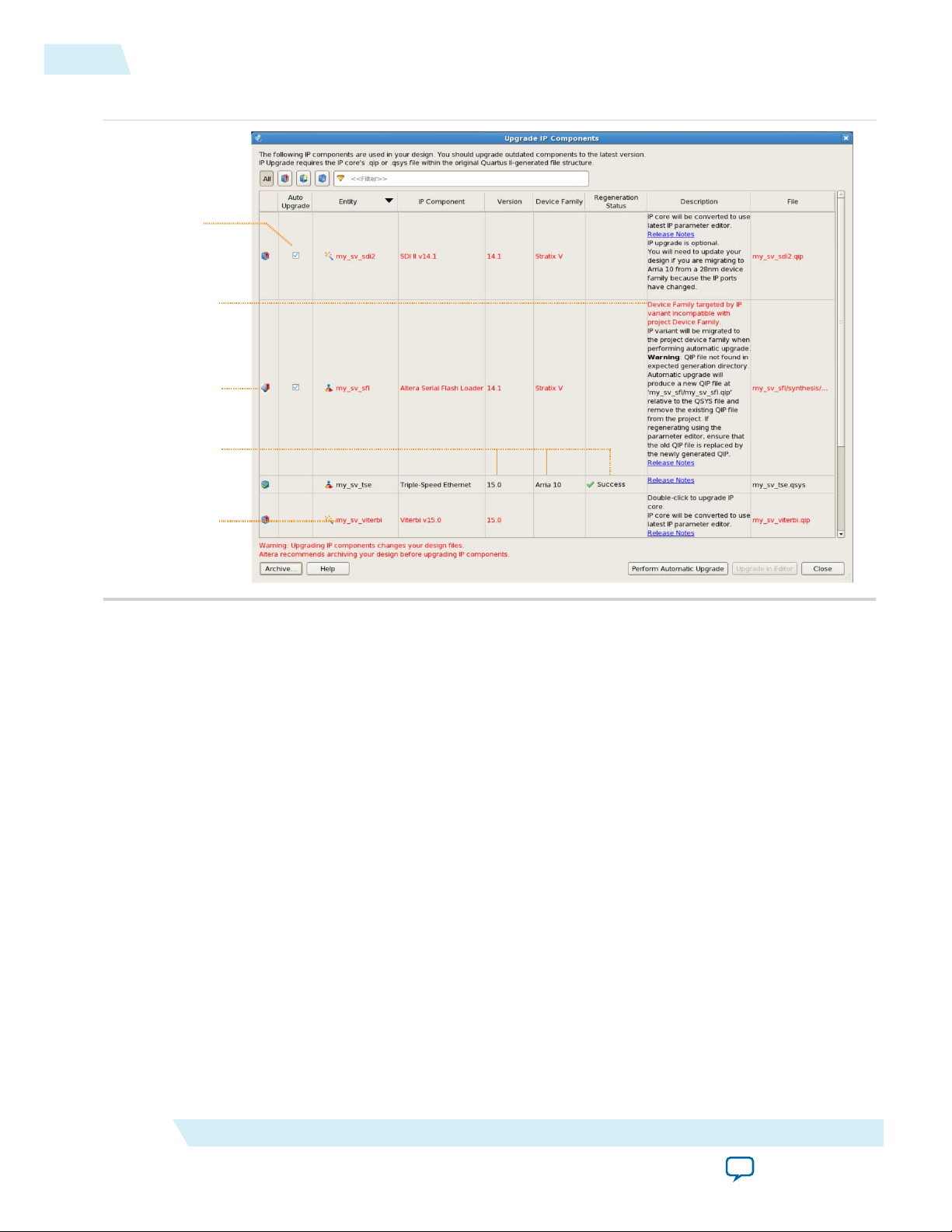
Upgrading Outdated IP Cores
Altera IP components are version-specific with the Quartus II software. The Quartus II software alerts
you when your IP core is outdated. Click Project > Upgrade IP Components to easily identify and
upgrade outdated IP cores.
To upgrade outdated IP cores appropriately, your restored project archive must retain the original
Quartus II-generated file structure. Failure to upgrade outdated IP cores can result in a mismatch between
the outdated IP core variation and the current supporting libraries.
Altera Corporation
Getting Started with LL Ethernet 10G MAC
Send Feedback
Page 18
UG-01144
2014.12.15
Migrating IP Cores to a Different Device
Altera verifies that the current version of the Quartus II software compiles the previous version of each IP
core. The MegaCore IP Library Release Notes and Errata reports any verification exceptions. Altera does
not verify compilation for IP cores older than the previous release.
Figure 2-4: Upgrading IP Components in Project Navigator
Related Information
MegaCore IP Library Release Notes and Errata
2-9
Migrating IP Cores to a Different Device
IP migration allows you to target the latest device families with IP originally generated for a different
device. Some Altera IP cores migrate automatically, some IP cores require manual IP regeneration, and
some do not support device migration and must be replaced in your design.
The text and icons in the Upgrade IP Components dialog box identifies the migration support for each
IP core in the design.
Note:
Migration of some IP cores requires installed support for the original and migration device
families. For example, migration from a Stratix V device to an Arria 10 device requires installation
of Stratix V and Arria 10 device families with the Quartus II software.
Getting Started with LL Ethernet 10G MAC
Send Feedback
Altera Corporation
Page 19
Double-click to
upgrade in editor
(no auto upgrade)
Upgrade required
Migration details
Supports Auto
upgrade
Upgrade success
2-10
Migrating IP Cores to a Different Device
Figure 2-5: Upgrading IP Cores
UG-01144
2014.12.15
1. Click File > Open Project and open the Quartus II project containing IP for migration to another
device in the original version of the Quartus II software.
2. To specify a different target device for migration, click Assignments > Device and select the target
device family.
3. To display IP cores requiring migration, click Project > Upgrade IP Components. The Description
field prompts you to run auto update or double-click IP cores for migration.
4. To migrate one or more IP cores that support automatic upgrade, ensure that the Auto Upgrade
option is turned on for the IP core(s), and then click Perform Automatic Upgrade. The Status and
Version columns update when upgrade is complete.
5. To migrate an IP core that does not support automatic upgrade, double-click the IP core name, and
then click OK. The parameter editor appears.
a. If the parameter editor specifies a Currently selected device family, turn off Match project/
default, and then select the new target device family.
b. Click Finish to migrate the IP variation using best-effort mapping to new parameters and settings.
A new parameter editor opens displaying best-effort mapped parameters.
c. Click Generate HDL, and then confirm the Synthesis and Simulation file options. Verilog HDL is
the defauilt output file format specified. If your original IP core was generated for VHDL, select
VHDL to retain the original output format.
Altera Corporation
Getting Started with LL Ethernet 10G MAC
Send Feedback
Page 20

UG-01144
2014.12.15
Design Considerations
2-11
6. To regenerate the new IP variation for the new target device, click Generate. When generation is
complete, click Close.
7. Click Finish to complete migration of the IP core. Click OK if you are prompted to overwrite IP core
files. The Device Family column displays the new target device name when migration is complete. The
migration process replaces <my_ip>.qip with the <my_ip>.qsys top-level IP file in your project.
Note: If migration does not replace <my_ip>.qip with <my_ip>.qsys, click Project > Add/Remove
Files in Project to replace the file in your project.
8. Review the latest parameters in the parameter editor or generated HDL for correctness. IP migration
may change ports, parameters, or functionality of the IP core. During migration, the IP core's HDL
generates into a library that is different from the original output location of the IP core. Update any
assignments that reference outdated locations. If your upgraded IP core is represented by a symbol in a
supporting Block Design File schematic, replace the symbol with the newly generated <my_ip>.bsf
after migration.
Note: The migration process may change the IP variation interface, parameters, and functionality.
This may require you to change your design or to re-parameterize your variant after the
Upgrade IP Components dialog box indicates that migration is complete. The Description
field identifies IP cores that require design or parameter changes.
Related Information
Altera IP Release Notes
Design Considerations
Migrating from Legacy Ethernet 10G MAC to LL Ethernet 10G MAC
Altera recommends the following migration path. Migrating your existing design in this manner allows
you to take advantage of the benefits of LL Ethernet 10G MAC—low resource count and low latency.
Migration—32-bit Datapath on Avalon-ST Interface
This migration path implements 32-bit datapath on the Avalon ST and Avalon-MM interfaces.
1. Instantiate the LL Ethernet 10G MAC IP core in your design. If you are using a PHY with 64-bit SDR
XGMII interface, turn on the Use legacy Ethernet 10G MAC XGMII Interface option.
2. Modify your user logic to accommodate 32-bit datapaths on Avalon-ST TX and RX data interfaces.
3. Ensure that tx_312_5_clk and rx_312_5_clk are connected to 312.5-MHz clock sources. Altera
recommends that you use the same clock source for these clock signals.
4. Update the register offsets to the offsets of the LL Ethernet 10G MAC. The configuration registers of
the LL Ethernet 10G MAC allow access to new features such as error correction and detection on
memory blocks.
5. If you turn on the Use legacy Ethernet 10G MAC XGMII Interface option, add a 156.25 MHz clock
source for tx_156_25_clk and rx_156_25_clk. This 156.25 MHz clock source must be rise-to-rise
synchronous to the 312.5 MHz clock source.
6. Ensure that csr_clk is within 125 MHz to 156.25 MHz. Otherwise, some statistic counters may not be
accurate.
Getting Started with LL Ethernet 10G MAC
Send Feedback
Altera Corporation
Page 21

2-12
Migration—Maintains 64-bit on Avalon-ST Interface
Migration—Maintains 64-bit on Avalon-ST Interface
This migration path implements 32-bit to 64-bit adapters on the Avalon ST interface and XGMII, and
uses the same register offsets to maintain backward compatibility with the legacy 10-Gbps Ethernet
(10GbE) MAC IP Core.
1. Instantiate the LL Ethernet 10G MAC IP core in your design. To maintain compatibility on the
interfaces, turn on the Use legacy Ethernet 10G MAC XGMII Interface, Use legacy Ethernet 10G
MAC Avalon Memory-Mapped Interface, and Use legacy Ethernet 10G MAC Avalon Streaming
Interface options.
2. Ensure that tx_312_5_clk and rx_312_5_clk are connected to 312.5-MHz clock sources. Altera
recommends that you use the same clock source for these clock signals.
3. Add a 156.25-MHz clock source for tx_156_25_clk and rx_156_25_clk. This 156.25 MHz clock
source must be rise-to-rise synchronous to the 312.5 MHz clock source.
4. Ensure that csr_clk is within 125 MHz to 156.25 MHz. Otherwise, some statistic counters may not be
accurate.
Timing Constraints
Altera provides timing constraint files (.sdc) to ensure that the IP core meets the design timing
requirements in Altera devices. The files constraints the false paths and multi-cycle paths in the IP core.
The timing constraints files are specified in the <variation_name>.qip file and is automatically included in
the Quartus II project files.
UG-01144
2014.12.15
The timing constraints files are in the IP directory. You can edit these files as necessary. They are for clock
crossing logic and grouped as below:
• Pseudo-static CSR fields
• Clock crosser
• Dual clock FIFO
Note:
For the IP to work correctly, there must be no other timing constraints files cutting or overriding
the paths, for example, set_false_path, set_clock_groups, at the project level.
Pseudo-Static CSR Fields
Most of the configuration registers in the MAC IP core must not be programmed when the MAC is in
operation. As such, they are not synchronized to reduce resource usage. These registers are all in the
set_false_path constraint.
Clock Crosser
Clock crossers perform multi-bit signals crossing from one clock domain to another.
The working principle of the clock crosser is to let the crossed-over data stabilize first before indicating
that the data is valid in the latched clock domain. Using such structure, the data bits must not skew for
more than one latched clock period. The timing constraint file applies a common timing check over all
the clock crossers irrespective of their latched clock domain. This is over-pessimistic for signals crossing
into the CSR clock, but there are no side-effects, like significant run-time impact and false violations,
during the internal testing. If your design runs into clock crosser timing violation paths within the IP and
the latched clock domain is csr_clk, you can dismiss the violation manually or by editing the .sdc file if
the violation is less than one csr_clk period.
Altera Corporation
Getting Started with LL Ethernet 10G MAC
Send Feedback
Page 22

UG-01144
2014.12.15
Dual Clock FIFO
Dual Clock FIFO
2-13
The timing constraint file uses the set_net_delay to constraint the fitter placement and set_max_skew to
perform timing check on the paths. For a project with very high device utilization, Altera recommends
that you implement addition steps like floor planning or LogicLock to aid the place-and-route process.
The additional steps can give a more consistent timing closure along these paths instead of only relying on
the set_net_delay.
A caveat of using set_max_skew is that it does not analyze whether the insertion delay of the path in
concern exceeds a limit. In other words, a path could meet skew requirement but have longer than
expected insertion delay. If this is not checked, it may cause functional failure in certain latency-sensitive
paths. Therefore, a custom script (alt_em10g32_clock_crosser_timing_info.tcl) is available for you to check
that the round-trip clock crosser delay is within expectation. To use this script, manually add it to the user
flow and run it. To ensure that the IP core operates correctly, the results must be positive (no error).
The bit skew of the dual clock FIFO gray-coded pointers must be within one 312.5 MHz clock period.
The timing constraint file uses the set_net_delay to constraint the fitter placement and set_max_skew to
perform timing check on the paths. For a project with very high device utilization, Altera recommends
that you implement addition steps like floor planning or LogicLock to aid the place-and-route process.
The additional steps can give a more consistent timing closure along these paths instead of only relying on
the set_net_delay.
Getting Started with LL Ethernet 10G MAC
Send Feedback
Altera Corporation
Page 23

2014.12.15
MAC TX
Control & Status
Registers
MAC RX
Clock & Reset
LL Ethernet 10G MAC
CSR Adapter
(Optional)
Avalon-ST 32/64b Adapter
(Optional)
XGMII SDR 32/64b Adapter
(Optional)
32-Bit XGMII Transmit Interface
8-Bit GMII Transmit Interface
4-Bit MII Transmit Interface
32-Bit XGMII Receive Interface
8-Bit GMII Receive Interface
4-Bit MII Receive Interface
64-Bit XGMII
Receive Interface
64-Bit XGMII
Transmit Interface
64-Bit XGMII
Receive Interface
64-Bit XGMII
Transmit Interface
Flow
Control
Link
Fault
Respective
Domains
Clock & Reset
Signals
Clock & Reset
Signals
Clock & Reset
Signals
32-Bit Avalon-ST
Transmit Interface
32-Bit Avalon-MM
Interface
32-Bit Avalon-ST
Receive Interface
Notes:
(1) Applies to 1G/10G and Multi Speed MAC only.
(2) Applies to Multi Speed MAC only.
(1)
(1)
(2)
(2)
www.altera.com
101 Innovation Drive, San Jose, CA 95134
Functional Description of LL Ethernet 10G MAC
3
UG-01144
Subscribe
Send Feedback
The Low Latency (LL) Ethernet 10G MAC IP core handles the flow of data between a client and an
Ethernet network through an Ethernet PHY. On the transmit path, the MAC IP core accepts client frames
and constructs Ethernet frames by inserting various control fields, such as checksums before forwarding
them to the PHY. Similarly, on the receive path, the MAC accepts Ethernet frames via a PHY, performs
checks, and removes the relevant fields before forwarding the frames to the client. You can configure the
MAC IP core to collect statistics on both transmit and receive paths.
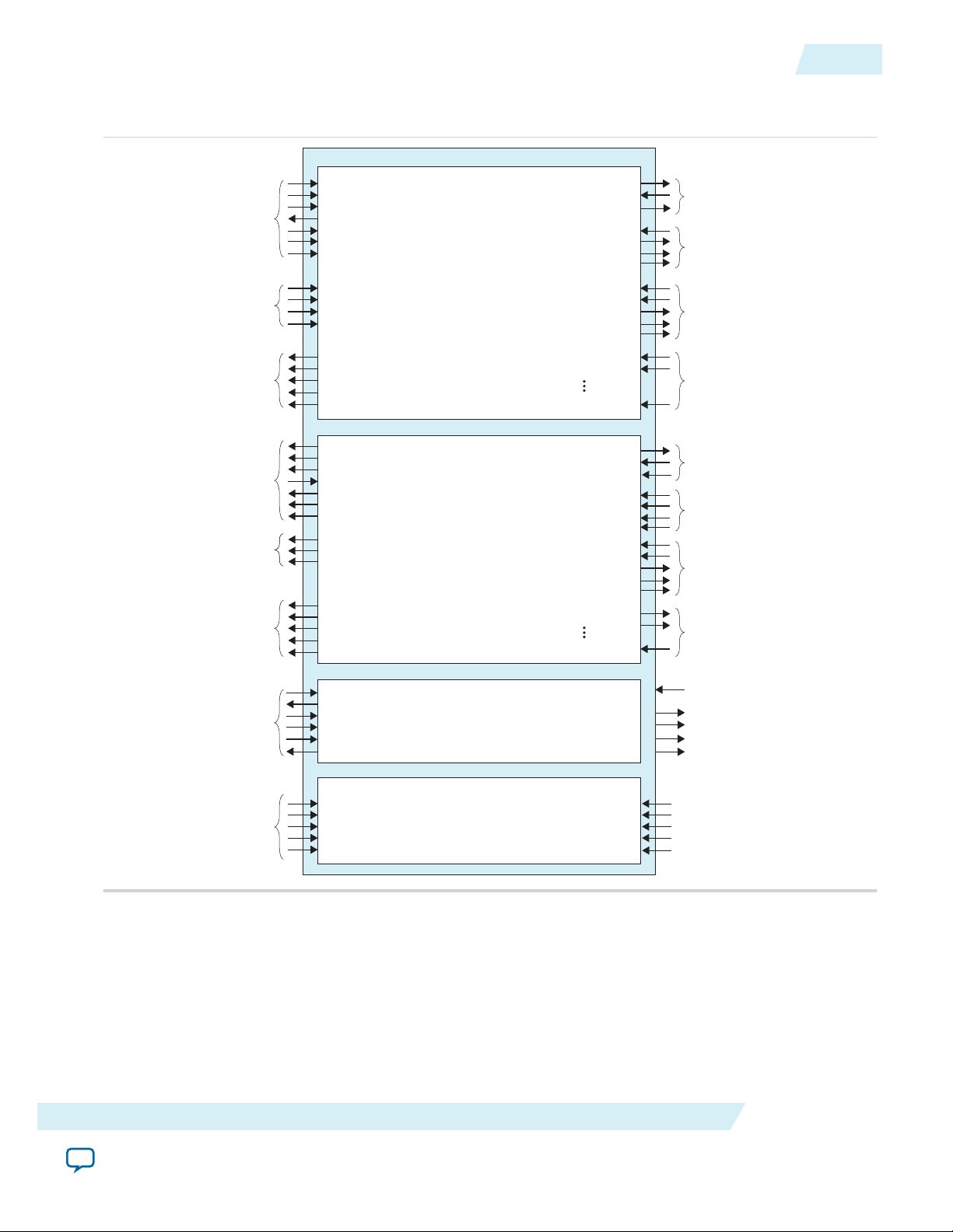
Architecture
The LL Ethernet 10G MAC IP core is a composition of the following blocks: MAC receiver (MAC RX),
MAC transmitter (MAC TX), configuration and status registers, and clock and reset.
Figure 3-1: LL Ethernet 10G MAC Block Diagram
©
2015 Altera Corporation. All rights reserved. ALTERA, ARRIA, CYCLONE, ENPIRION, MAX, MEGACORE, NIOS, QUARTUS and STRATIX words and logos are
trademarks of Altera Corporation and registered in the U.S. Patent and Trademark Office and in other countries. All other words and logos identified as
trademarks or service marks are the property of their respective holders as described at www.altera.com/common/legal.html. Altera warrants performance
of its semiconductor products to current specifications in accordance with Altera's standard warranty, but reserves the right to make changes to any
products and services at any time without notice. Altera assumes no responsibility or liability arising out of the application or use of any information,
product, or service described herein except as expressly agreed to in writing by Altera. Altera customers are advised to obtain the latest version of device
specifications before relying on any published information and before placing orders for products or services.
ISO
9001:2008
Registered
Page 24

3-2
Interfaces
Interfaces
Table 3-1: Interfaces
Interfaces Description
UG-01144
2014.12.15
Avalon-ST Interface
The client-side interface of the MAC employs the Avalon-ST protocol,
which is a synchronous point-to-point, unidirectional interface that
connects the producer of a data stream (source) to a consumer of the data
(sink). The key properties of this interface include:
• Frame transfers marked by startofpacket and endofpacket signals.
• Signals from source to sink are qualified by the valid signal.
• Errors marking a current packet are aligned with the end-of-packet cycle.
• Use of the ready signal by the sink to backpressure the source.
In the MAC IP core, the Avalon-ST interface acts as a sink in the TX
datapath and source in the RX datapath. This interface supports packets,
backpressure, and error detection. It operates at 312.5 MHz. The ready
latency on this interface is 0.
Avalon-MM Control and
Status Register Interface
The Avalon-MM control and status register interface is an Avalon-MM slave
port. This interface uses word addressing which provides access to the
configuration and status registers, and statistics counters.
XGMII In 10G mode, the network-side interface of the MAC IP core implements the
XGMII protocol. Depending on the configuration, the XGMII consists of 32or 64-bit data bus and 4- or 8-bit control bus operating at 312.5 MHz. This
interface operates at 322.265625 MHz if the 10GBASE-R register mode is
enabled. The data bus carries the MAC frame with the most significant byte
occupying the least significant lane.
GMII
MII In 10M or 100M mode, the network-side interface of the MAC IP core
Altera Corporation
In 1G/10G and 10M/100M/1G/10G operating modes, the network-side
interface of the MAC IP core implements 8 bits wide GMII protocol when
the MAC operates at 1 Gbps. This 8-bit interface supports gigabit operations
at 125 MHz.
implements the MII protocol. This 4-bit MII supports 10-Mbps and 100Mbps operations at 125 MHz, with a clock enable signal that divides the
clock to effective rates of 2.5 MHz for 10 Mbps and 25 MHz for 100 Mbps.
Functional Description of LL Ethernet 10G MAC
Send Feedback
Page 25
MAC RX
Clock and
Reset
csr_clk
csr_rst_n
tx_312_5_clk
tx_156_25_clk
rx_156_25_clk
rx_rst_n
tx_rst_n
rx_312_5_clk
Avalon-MM
Control and
Status Interface
csr_read
csr_readdata[31:0]
csr_write
csr_writedata[31:0]
csr_address[12:0]
csr_waitrequest
XGMII Transmit
MAC TX
xgmii_tx_data[31:0]
link_fault_status_xgmii_tx_data[1:0]
GMII Transmit
(1G/10Gbps, multi-speed)
gmii_tx_clk
gmii_tx_d[7:0]
gmii_tx_en
gmii_tx_err
MII Transmit
(multi-speed)
tx_clkena
tx_clkena_half_rate
mii_tx_d[3:0]
mii_tx_en
mii_tx_err
Avalon-ST Transmit
Data Interface
avalon_st_tx_startofpacket
avalon_st_tx_endofpacket
avalon_st_tx_valid
avalon_st_tx_ready
avalon_st_tx_error
avalon_st_tx_data[31:0]
avalon_st_tx_empty[1:0]
Avalon-ST Transmit
Flow Control Interface
avalon_st_pause_data[1:0]
avalon_st_tx_pause_length_valid
avalon_st_tx_pause_length_data[15:0]
avalon_st_tx_pfc_gen_data[n]
Avalon-ST Transmit
Status Interface
avalon_st_txstatus_valid
avalon_st_txstatus_data[39:0]
avalon_st_txstatus_error[6:0]
avalon_st_tx_pfc_status_valid
avalon_st_tx_pfc_status_data[n]
IEEE 1588v2
Interface
tx_egress_timestamp_request_valid
tx_egress_timestamp_request_fingerprint[n]
tx_path_delay_10g_data[15:0]
xgmii_rx_data[31:0]
link_fault_status_xgmii_rx_data[1:0]
XGMII Receive
gmii_rx_clk
gmii_rx_d[7:0]
gmii_rx_dv
gmii_rx_err
GMII Receive
(1G/10Gbps, multi-speed)
rx_clkena
rx_clkena_half_rate
mii_rx_d[3:0]
mii_rx_dv
mii_rx_err
MII Receive
(multi-speed)
avalon_st_rx_startofpacket
avalon_st_rx_endofpacket
avalon_st_rx_valid
avalon_st_rx_ready
avalon_st_rx_error[5:0]
avalon_st_rx_data[31:0]
avalon_st_rx_empty[1:0]
Avalon-ST Receive
Data Interface
avalon_st_rx_pause_length_valid
avalon_st_rx_pause_length_data[15:0]
avalon_st_rx_pfc_pause_data[n]
Avalon-ST
Receive Flow
Control Interface
avalon_st_rxstatus_valid
avalon_st_rxstatus_data[39:0]
avalon_st_rxstatus_error[6:0]
avalon_st_rx_pfc_status_valid
avalon_st_rx_pfc_status_data[n]
Avalon-ST Receive
Status Interface
rx_ingress_timestamp_96b_data[95:0]
rx_ingress_timestamp_96b_valid
rx_path_delay_10g_data[15:0]
IEEE 1588v2
Time-Stamp
Interface
speed_sel
ecc_err_det_corr
ecc_err_det_uncorr
tx_xcvr_clk
rx_xcvr_clk
xgmii_tx_control[3:0]
unidirectional_en
unidirectional_remote_fault_dis
LL Ethernet 10G MAC
Avalon-MM
Control and Reset
xgmii_rx_control[3:0]
UG-01144
2014.12.15
Figure 3-2: Interface Signals
The inclusion and width of some signals depend on the operating mode and features selected.
Interfaces
3-3
Related Information
Interface Signals for LL Ethernet 10G MAC on page 5-1
Describes each signal in detail.
Functional Description of LL Ethernet 10G MAC
Send Feedback
Altera Corporation
Page 26
Client - MAC Tx Interface
(optional)
Client Frame
MAC Frame
Destination
Addr[47:0]
Source
Addr[47:0]
Type/
Length[15:0]
Payload
[<p-1>:0]
Destination
Addr[47:0]
SFD[7:0]
Preamble
[55:0]
CRC32
[31:0]
PAD [<s>]
Source
Addr[47:0]
Client-Defined Preamble
[63:0]
(optional)
Type/
Length[15:0]
Payload
[<p-1>:0]
PAD [<s>]
CRC32
[31:0]
EFD[7:0]
IPG
[<l-1>:0]
Frame Length
(1) (2)
(3)
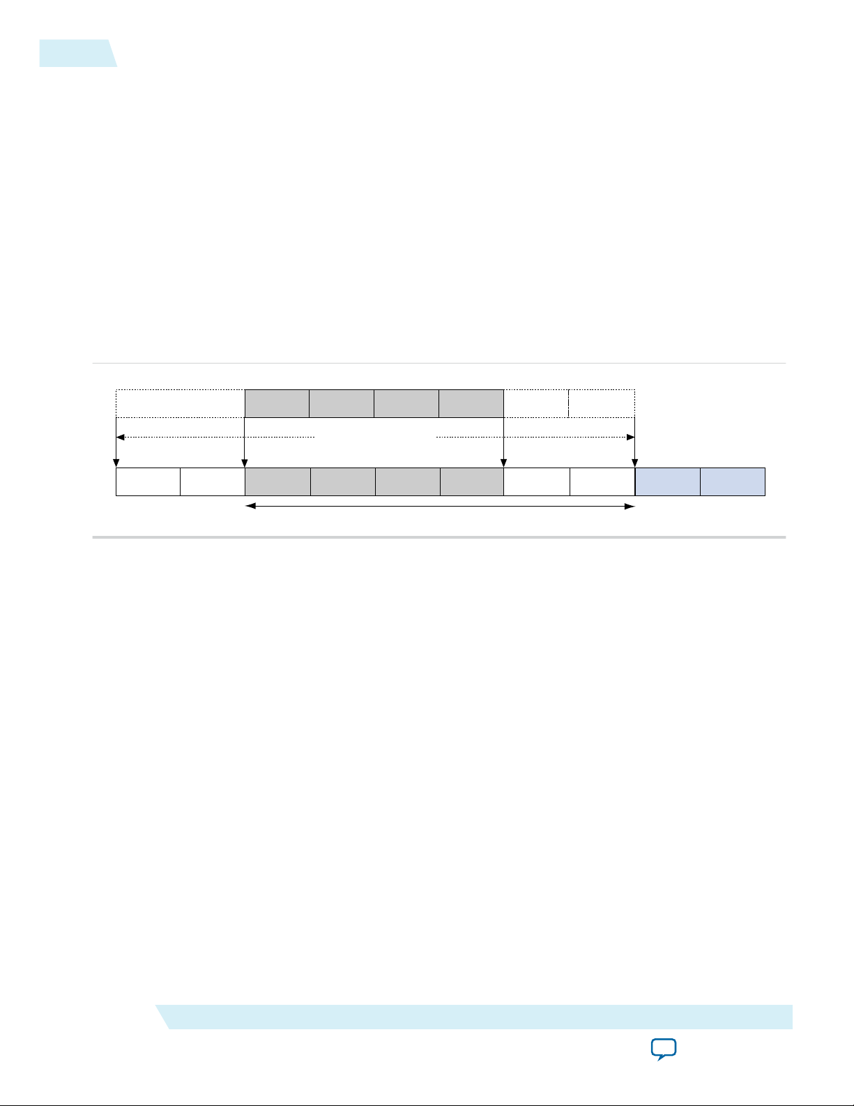
3-4
Frame Types
Frame Types
The MAC IP core supports the following frame types:
• Basic Ethernet frames, including jumbo frames.
• VLAN and stacked VLAN frames.
• Control frames, which include pause and PFC frames.
TX Datapath
The MAC TX receives the client payload data with the destination and source addresses, and appends
various control fields depending on the MAC configuration.
Figure 3-3: Typical Client Frame at TX Interface
UG-01144
2014.12.15
Padding Bytes Insertion
Address Insertion
Altera Corporation
By default, the MAC TX inserts padding bytes (0x00) into TX frames to meet the following minimum
payload length:
• 46 bytes for basic frames
• 42 bytes for VLAN tagged frames
• 38 bytes for stacked VLAN tagged frames
Ensure that CRC-32 insertion is enabled when padding bytes insertion is enabled.
You can disable padding bytes insertion by setting the tx_pad_control register to 0. When disabled, the
MAC IP core forwards the frames to the PHY-side interface without padding. Ensure that the minimum
payload length is met; otherwise the current frame may get corrupted. You can check for undersized
frames by referring to the statistics collected.
By default, the MAC TX retains the source address received from the client. You can configure the MAC
TX to replace the source address with the primary MAC address specified in the tx_addrins_macaddr0
and tx_addrins_macaddr1 registers by setting the bit tx_src_addr_override[0] to 1.
Functional Description of LL Ethernet 10G MAC
Send Feedback
Page 27

tx_312_5_clk
avalon_st_tx_ready
avalon_st_tx_valid
avalon_st_tx_startofpacket
avalon_st_tx_endofpacket
avalon_st_tx_data[31:0]
avalon_st_tx_empty[1:0]
avalon_st_tx_error
...00000000
0
rx_312_5_clk
avalon_st_rx_ready
avalon_st_rx_valid
avalon_st_rx_startofpacket
avalon_st_rx_endofpacket
avalon_st_rx_data[31:0]
avalon_st_rx_empty[1:0]
avalon_st_rx_error[5:0]
...4EB30AF4
0
UG-01144
2014.12.15
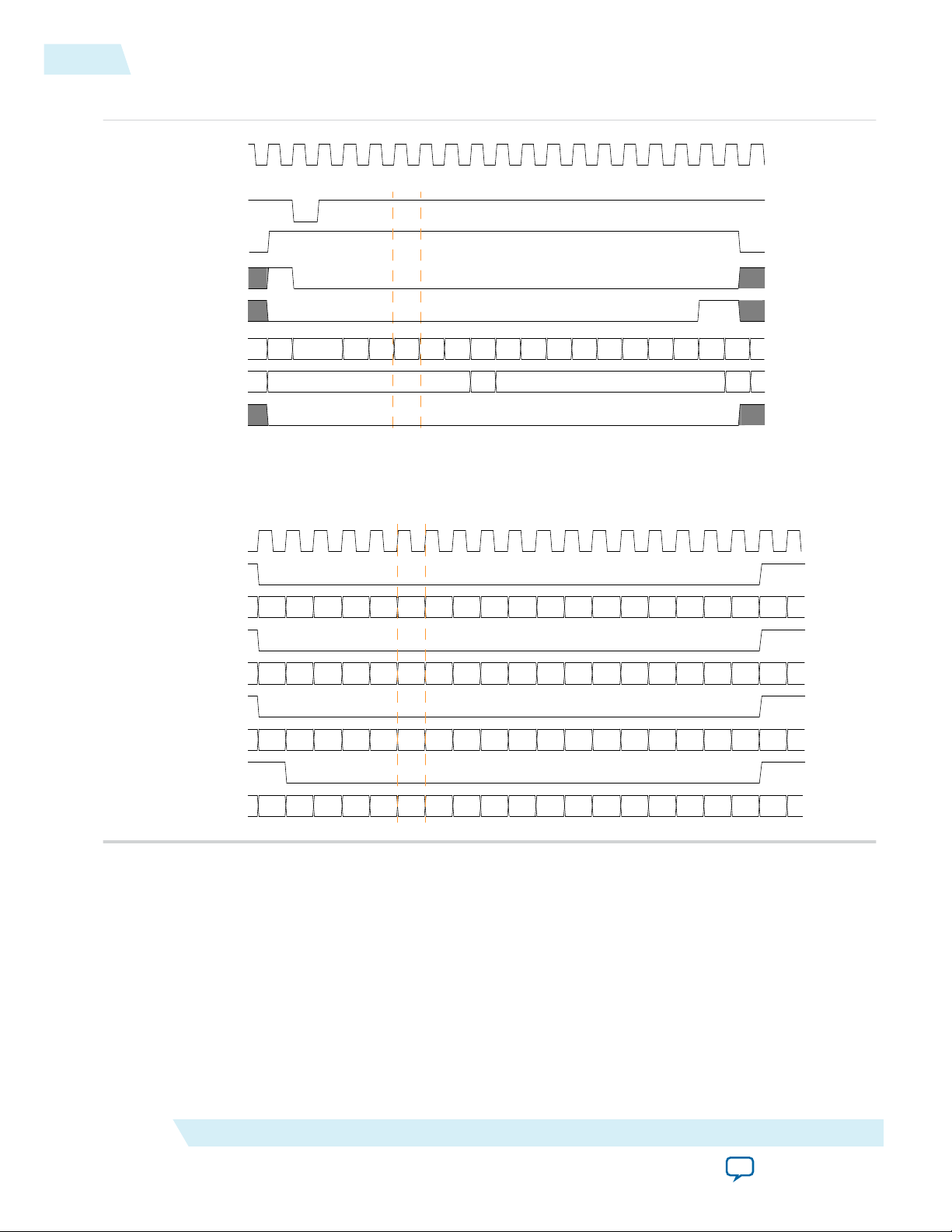
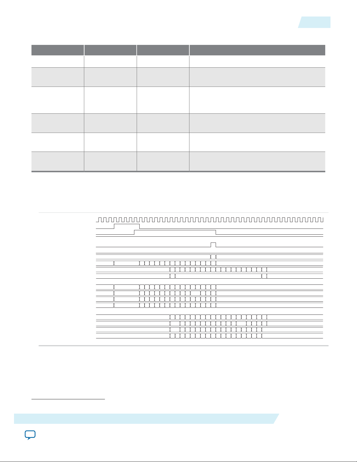
CRC-32 Insertion
By default, the MAC TX computes and inserts CRC-32 checksum into TX frames. The MAC TX
computes the CRC-32 checksum over frame bytes that include the source address, destination address,
length, data, and padding bytes. The computation excludes the preamble and SFD bytes. The MAC TX
then inserts the CRC-32 checksum into the TX frame. Bit 31st of the checksum occupies the least signifi‐
cant bit of the first byte in the CRC field.
You can disable this function by setting the tx_crc_control[1] register bit to 0.
The following figure shows the timing diagram on the Avalon-ST data interfaces where CRC insertion is
enabled on transmit and CRC removal is disabled on receive. The frame from the client is without
CRC-32 checksum. The MAC TX inserts the CRC-32 checksum (4EB00AF4) into the frame. The frame is
then looped back to the RX datapath with the CRC-32 checksum.
Figure 3-4: Avalon-ST TX and RX Interfaces with CRC Insertion Enabled
CRC-32 Insertion
3-5
Functional Description of LL Ethernet 10G MAC
Send Feedback
Altera Corporation
Page 28

tx_312_5_clk
avalon_st_tx_ready
avalon_st_tx_valid
avalon_st_tx_startofpacket
avalon_st_tx_endofpacket
avalon_st_tx_data[31:0]
avalon_st_tx_empty[1:0]
avalon_st_tx_error
0
rx_312_5_clk
avalon_st_rx_ready
avalon_st_rx_valid
avalon_st_rx_startofpacket
avalon_st_rx_endofpacket
avalon_st_rx_data[31:0]
avalon_st_rx_empty[1:0]
avalon_st_rx_error[5:0]
...4EB30AF4
...4EB30AF4
0
3-6
XGMII Encapsulation
The following figure shows the timing diagram on the Avalon-ST data interfaces where CRC insertion is
disabled on transmit and CRC removal is disabled on receive. The MAC TX receives the frame from the
client with a CRC-32 checksum (4EB00AF4). The frame with the same CRC-32 checksum is then looped
back to the RX datapath.
Figure 3-5: Avalon-ST TX and RX Interface with CRC Insertion Disabled
UG-01144
2014.12.15
XGMII Encapsulation
By default, the MAC TX inserts 7-byte preamble, 1-byte SFD and 1-byte EFD (0xFD) into frames received
from the client.
The MAC TX also supports custom preamble in 10G operations. To use custom preamble, set the
tx_preamble_control register to 1. In this mode, the MAC TX accepts the first 8 bytes in the frame from
the client as custom preamble and inserts only 1-byte EFD (0xFD) into the frame. The MAC TX also
replaces the first byte of the preamble with 1-byte START (0xFB).
Altera Corporation
Functional Description of LL Ethernet 10G MAC
Send Feedback
Page 29

UG-01144
2014.12.15
An underflow could occur on the Avalon-ST TX interface. An underflow occurs when the
avalon_st_tx_valid signal is deasserted in the middle of frame transmission. When this happens, the
10GbE MAC TX inserts an error character |E| into the frame and forwards the frame to the XGMII.
Inter-Packet Gap Generation and Insertion
The MAC TX maintains an average IPG between TX frames as required by the IEEE 802.3 Ethernet
standard. The average IPG is maintained at 96 bit times (12 byte times) using the deficit idle count (DIC).
The MAC TX inserts or deletes idle bytes depending on the value of the DIC; the DIC must be between 9
to 15 bytes. Averaging the IPG ensures that the MAC utilizes the maximum available bandwidth.
XGMII Transmission
On the XGMII, the MAC TX performs the following:
• Aligns the first byte of the frame to lane 0 of the interface.
• Performs endian conversion. Transmit frames received from the client on the Avalon-ST interface are
big endian. Frames transmitted on the XGMII are little endian; the MAC TX therefore transmits
frames on this interface from the least significant byte.
The following figure shows the timing on the Avalon-ST TX data interface and XGMII. The least signifi‐
cant byte of the value in D5 is transmitted first on the XGMII.
Inter-Packet Gap Generation and Insertion
3-7
Functional Description of LL Ethernet 10G MAC
Send Feedback
Altera Corporation
Page 30
55
(1)
D5 CC CC EE 01 05 09 0D
55
(1)
55 88 EE AA 00 04 08 0C
55
(1)
55 EE CC 2E 03 07 0B 0F
FB 55 EE AA 88 00 02 06 0A 0E
CC
tx_312_5_clk
0 4
D1
D2 D3 D4 D5 D6 D7 D8
15 19 1D 21 25 29 2D F4 07
14 18 1C 20 24 28 2C 0A 07
13 17 1F 23 27 2B B3 07
12 16 1A 1E 22 26 2A 4E FD
1B
10
11
07
0 4
D9
D10 D11 D12 D13 D14 D15
D16 D17
D1: 555555D5
D2: EECC88CC
D3: AAEEEECC
D4: 88CCAAEE
D5: 002E0001
D6: 02030405
D7: 06070809
D8: 0A0B0C0D
D9: 0E0F1011
D10: 12131415
D11: 16171819
D12: 1A1B1C1D
D13: 1E1F2021
D14: 22232425
D15: 26272829
D16: 2A2B2C2D
D17: 4EB30AF4
avalon_st_tx_ready
avalon_st_tx_valid
avalon_st_tx_startofpacket
avalon_st_tx_endofpacket
avalon_st_tx_data[31:0]
avalon_st_tx_empty[1:0]
avalon_st_tx_error
tx_312_5_clk
xgmii_tx_control[3]
xgmii_tx_data[31:24]
xgmii_tx_control[2]
xgmii_tx_data[23:16]
xgmii_tx_control[1]
xgmii_tx_data[15:8]
xgmii_tx_control[0]
xgmii_tx_data[7:0]
Data value:
3-8
Unidirectional Feature
Figure 3-6: Endian Conversion
UG-01144
2014.12.15
Unidirectional Feature
The MAC TX implements the unidirectional feature as specified by clause 66 in the IEEE802.3 specifica‐
tion. This is an optional feature supported only in 10G operations. When you enable this feature, two
output ports—unidirectional_en, unidirectional_remote_fault_dis— and two register fields—
UniDir_En (Bit 0), UniDirRmtFault_Dis (Bit 1)— are accessible to control the TX XGMII interface.
Altera Corporation
Functional Description of LL Ethernet 10G MAC
Send Feedback
Page 31
tx_312_5_clk
avalon_st_tx_startofpacket
avalon_st_tx_valid
avalon_st_tx_ready
avalon_st_tx_endofpacket
avalon_st_tx_error
avalon_st_tx_empty[1:0]
avalon_st_tx_data[31:0]
xgmii_tx_data[31:0]
xgmii_tx_control[3:0]
avalon_st_tx_data[31:24]
avalon_st_tx_data[23:16]
avalon_st_tx_data[15:8]
avalon_st_tx_data[7:0]
xgmii_tx_data[7:0]
xgmii_tx_data[15:8]
xgmii_tx_data[23:16]
xgmii_tx_data[31:24]
0 3 0
0f8e_8236 0023_4567 *5 *1 *2 *2 *5 *b *c *7 *e
*d *5 *3 *e *5 *0
cc6b_d355
0707_0707 *b *5 *0 *9 *1 *0 *c *e *b
*6 *1 *0 *b *7 *6
*d *d *d *2 0707_0707
f 1 0 e f
0f 00 89 f1 00 fc ce 6b 26 01 e0
0b 87 a6 7d 4d 5d
cc
8e
23
ab c7 2f 8c 3f 9f d9 77 59
71 e5 3a 42 00
6b
82 45 c4 e9 fb 00 62 f7 80 84 09
c5 21 65 4b b1 00
d3
36 67 d5 61 d2 82 85 4b fc 67 9e
9d 45 23 ee a5 00
55
07 7dfb 55 00 89 f1 00 fc ce 6b
26 01 e0 0b 87 a6
07
07
3a
55 23 ab c7 2f 8c 3f 9f
d9 77 71 e5
07
07 4b55 45 c4 e9 fb 00 62 f7
80 84 09 c5 21 65
07
07 ee55 d5 67 d5 61 d2 82 85 4b
fc 67 9e 8d 45 23
07
a2
4d 5d
fd
42 13
b1 8a
a5 d0
59
UG-01144
2014.12.15
Table 3-2: Register Field and Link Status
Bit 0 Register Field Bit 1 Register Field Link Status TX XGMII Interface Behavior
Don't care Don't care No link fault Continue to allow normal packet transmission.
0 Don't care Local fault Immediately override the current content with
1 0 Local fault Continue to send packet if there is one.
1 1 Local fault Continue to allow normal packet transmission
0 Don't care Remote fault Immediately override the current content with
1 Don't care Remote fault Continue to allow normal packet transmission
TX Timing Diagrams
TX Timing Diagrams
remote fault sequence.
Otherwise, override the IPG/IDLE bytes with
remote fault sequence.
(1)
(similar to no link fault).
IDLE control characters.
(similar to no link fault).
3-9
Figure 3-7: Normal Frame
The following diagram shows the transmission of a normal frame.
Functional Description of LL Ethernet 10G MAC
(1)
At least a full column of IDLE (four IDLE characters) must precede the remote fault sequence.
Send Feedback
Altera Corporation
Page 32

0 3
7c91_5b8d
*5 *_fff *fb *4 *5 *3 *f *0 *9 *a *1 *3 *0 *3 *0
0707_0707
*b *1 *_fff *ff *2 *0 *b *0 *e *5 *5 *6 *3 *0 *4 *c *0 *8 *d
f 1
7c
d1 ff 2b 00 5b 60 8e 65 25 36 13 10 04
81
bf ff 0098 2f 5d de 4b 4e 54 53 13 60 a1
83 001d 45 e3 5b 09 bb db 10 e8 86 a9
d5 0024 f5 f3 2f 20 69 ba 21 53 f0 83
ff 44
ff fb
5b
8d
fb 0422 00 5b 60 8e 65 25 36 13 10d1 ff
07
fd7c 00 38
*5 a133 2f 5d de 4b 4e 54 53 13 60*5 ff
07
00 7a
*5 a944 45 e3 5b 09 bb db 10 e8 86*5
07
00 9cff 00
*5 8355 f5 f3 2f 20 69 ba 21 53 f0*5
07
00 eeff 00
tx_312_5_clk
avalon_st_tx_startofpacket
avalon_st_tx_valid
avalon_st_tx_ready
avalon_st_tx_endofpacket
avalon_st_tx_error
avalon_st_tx_empty[1:0]
avalon_st_tx_data[31:0]
xgmii_tx_data[31:0]
xgmii_tx_control[3:0]
avalon_st_tx_data[31:24]
avalon_st_tx_data[23:16]
avalon_st_tx_data[15:8]
avalon_st_tx_data[7:0]
xgmii_tx_data[7:0]
xgmii_tx_data[15:8]
xgmii_tx_data[23:16]
xgmii_tx_data[31:24]
0
92e6_9b29 0faa_4s5e
92 0f
e6 aa
9b 4a
29 5e
0707_0707
f0
07
07
07
07
0 3
0
8190_a0b0 *a7 *8d *ed *05 *56 *f0 *d6 *44 *95 *f4 *38 *03 *31 *0b *7a *00 *0_a0b0 *d2 *96 *01 *5c *43 *cb *e3 b4c1_cafd *f0 *4c 0023_456
0707_0707 *fb *55 *81 *c0 *22 *3d *f5 *08 *d6 *7e *51 *37 *1a *95 *a2 *9f *96 *b9 *e3 *be *7_0707 *fb *55 *81 *c0 *22
f 1 0 e f 1 0
81 c0 15 3d f5 08 d6 7e 51 37 1a 95 a2 31 96 b9 e3 81 c0 d6 88 00 7b 31 0e b4 49 25 00
90 d0 83 61 1c 75 e3 f4 7b 99 cd bc 83 85 5a 00 90 d0 07 08 0a 40 9f 76 c1 04 8b 23
a0 e7 35 1b 2f ff 5a b1 fc 06 b2 a8 ca 54 0d 4f 00 a0 cd 39 00 1d 05 11 57 ca e1 27 45
b0 a7 8d ed 05 56 f0 d6 44 95 f4 38 ca 31 0b 7a 00 b0 d2 96 01 5c 43 cb e3 fd f0 4c 67
07 fb 55 81 c0 22 3d f5 08 d6 7e 51 37 1a 95 a2 9f 96 b9 e3 be 07 fb 55 81 c0 22
07 55 90 d0 33 61 1c 75 e3 f4 7b 99 cd bc 83 85 5a c7 fd 07 55 90 d0 33
07 55 a0 00 44 1b 2f ff 5a b1 fc 06 b2 a8 ca 54 0d 4f 53 07 55 a0 00 44
07 55 d5 b0 00 55 ed 05 56 f0 d6 44 95 f4 38 03 31 0b 7a 88 07 55 d5 b0 00 55
tx_312_5_clk
avalon_st_tx_startofpacket
avalon_st_tx_valid
avalon_st_tx_ready
avalon_st_tx_endofpacket
avalon_st_tx_error
avalon_st_tx_empty[1:0]
avalon_st_tx_data[31:0]
xgmii_tx_data[31:0]
xgmii_tx_control[3:0]
avalon_st_tx_data[31:24]
avalon_st_tx_data[23:16]
avalon_st_tx_data[15:8]
avalon_st_tx_data[7:0]
xgmii_tx_data[7:0]
xgmii_tx_data[15:8]
xgmii_tx_data[23:16]
xgmii_tx_data[31:24]
3-10
TX Timing Diagrams
Figure 3-8: Normal Frame with Preamble Passthrough Mode, Padding Bytes Insertion, and Source
Address Insertion Enabled
The following diagram shows the transmission of good frames with preamble passthrough mode, padding
bytes insertion, and source address insertion enabled.
UG-01144
2014.12.15
Figure 3-9: Back-to-back Transmission of Normal Frames with Source Address Insertion Enabled.
Altera Corporation
The following diagram shows back-to-back transmission of normal frames with source address insertion
enabled. The MAC primary address registers are set to 0x000022334455.
Functional Description of LL Ethernet 10G MAC
Send Feedback
Page 33

tx_312_5_clk
avalon_st_tx_startofpacket
avalon_st_tx_valid
avalon_st_tx_ready
avalon_st_tx_endofpacket
avalon_st_tx_error
avalon_st_tx_empty[1:0]
avalon_st_tx_data[31:0]
xgmii_tx_data[31:0]
xgmii_tx_control[3:0]
avalon_st_tx_data[31:24]
avalon_st_tx_data[23:16]
avalon_st_tx_data[15:8]
avalon_st_tx_data[7:0]
xgmii_tx_data[7:0]
xgmii_tx_data[15:8]
xgmii_tx_data[23:16]
xgmii_tx_data[31:24]
* * * * * * * ** * *3 ac8b_600d* * * * * * * * ** * * * * * * * ** * * * * * * * **
*
* * * * ***aa2f_4bbd **
*
*
* * * * * * * ** * * * *707 *b * * * * * **0 * * * * * * * ** * * * * * * * **
*
* * * * ** **707
*
** * * * * **b
0 f 1 0 1f0e
6f de b3 23 32 5f 00 3b89 a5 00 ac0b 71 a0 90 c9 4c f0 6c a461 f9 36 22 1a 21 b7 f3 bca3 69 30 fa 2e a9 87 bb dbf5
b5
84 22 ff 64 6700
4d
aa 2cea
c8
7a
2b d2 b4 5f 1f 37 23 05ab 1b ff 8b7e d3 bc 59 b0 db 15 ae ade2 02 0f 21 62 74 c0 36 c8 13 d9 12 15 f0 a4 00da
45
f9 37 ff bd 03ac
53
2f 4b81
e7
04
25 d4 48 e9 ad a5 45 e3f0 8f b7 60fa da d7 38 0f a9 60 be 344d 83 d4 8c68 5d e0 c1 26 74 95 65 ac ce 0079
85
e7 8a 5d f53b
ba
4b eb97
24
0df8 eb6e ff 03
89 8d 93 66 3a d5 67 62 94 f3 0d9c ee 3f 2c 44 d5 ca 11 6c85 4e 7b 26 64 d8 e7 0a 19 a4 5c 9e b0 004a
40
0a d5 5b a850
83
bd ce94
48
57 03bc ff 225e 48
fe 8d ad 56 98 fb 8f 50b3 6f de b3 07 fb 5f 00 89 3b a5 0b00 71 a0 90 c9 4c f0 6c a461 f9 30 22 1a 21 b7 f3 bca3
84
7a 69 2e 87a9
bb
fb07
22
ac23 4a fd 30 fa dbf5
7e
8d b9 81 16 88 54 ac b3fc 2b d2 b4 07 1f 37 23 ab 05 1b 7eff d3 bc 59 b0 db 15 ae ade2 02 0f 21 62 74 c0 36
f9
04 c8 12 f015
a4
4507
37
8b5f a6 13 d9 f4da
fd
2b 0f 49 ca 38 40 9f f814 25 d4 48 07 ad a5 45 f0 e3 8f fab7 da d7 38 0f a9 60 be 344d 83 d4 68 5d 8c e0 eb6e
e7
0d c1 95 ac65
ce
8507
8a
60e9 0a 26 74 0f79
d6 38 84 f0 3a 76 7f c59c 89 8d 93 07 3a d5 67 62 94 9cf3 ee 3f 2c 44 d5 ca 11 6c85 4e 7b 26 64 d8 03bc
0a
57 e7 a4 9e5c
b0
4007
d5
0d66 e7 0a 19 ce4a5e 48
0
c990_2f08
0
0707_0707
f 00f
*c61
*0707
97
36
6c
61
c9
90
2f
08
fc
07
07
07
07
07
07
07
07
tx_312_5_clk
avalon_st_tx_startofpacket
avalon_st_tx_valid
avalon_st_tx_ready
avalon_st_tx_endofpacket
avalon_st_tx_error
avalon_st_tx_empty[1:0]
avalon_st_tx_data[31:0]
xgmii_tx_data[31:0]
xgmii_tx_control[3:0]
avalon_st_tx_data[31:24]
avalon_st_tx_data[23:16]
avalon_st_tx_data[15:8]
avalon_st_tx_data[7:0]
xgmii_tx_data[7:0]
xgmii_tx_data[15:8]
xgmii_tx_data[23:16]
xgmii_tx_data[31:24]
pulse_tx_udf_errcnt
UG-01144
2014.12.15
TX Timing Diagrams
3-11
Figure 3-10: Back-to-back Transmission of Normal Frames with Preamble Passthrough Mode Enabled
The following diagram shows back-to-back transmission of normal frames with preamble passthrough
mode enabled.
Figure 3-11: Error Condition—Underflow
The following diagrams show an underflow on the transmit datapath followed by the transmission of a
normal frame.
An underflow happens in the middle of a frame that results in a premature termination on the XGMII.
The remaining data from the Avalon-ST transmit interface is still received after the underflow but the
data is dropped. The transmission of the next frame is not affected by the underflow.
Functional Description of LL Ethernet 10G MAC
Send Feedback
Altera Corporation
Page 34

tx_312_5_clk
avalon_st_tx_startofpacket
avalon_st_tx_valid
avalon_st_tx_ready
avalon_st_tx_endofpacket
avalon_st_tx_error
avalon_st_tx_empty[1:0]
avalon_st_tx_data[31:0]
xgmii_tx_data[31:0]
xgmii_tx_control[3:0]
avalon_st_tx_data[31:24]
avalon_st_tx_data[23:16]
avalon_st_tx_data[15:8]
avalon_st_tx_data[7:0]
xgmii_tx_data[7:0]
xgmii_tx_data[15:8]
xgmii_tx_data[23:16]
xgmii_tx_data[31:24]
pulse_tx_udf_errcnt
* *4 *f *3 *c *1 *e
*d *a *c *e *9 *7
c531_fcb6
*c *d *9 *e *3 *e *4 *5 *d
*2 *c *f *f *6 *0
*3 *6 *fe *7 0707_0707
0 f 0 f
fed9 6e 63 6e 74 d5 ed 42 cc
3f 5f 76 c0 93 b6
07
fe
1e c7 2f 1b 0c 02 37
39 3b 31
07
fe95 46 23 39 c1 d4 fc
a9 4a 37 8b 13 f0
07
fe48 c8 3f 14 84 6f 23 33 a1
5e 8d 1a fc 1e 49
07
fd
37 b8
a4 3a
37 e3
37 13
15
* *1 *6 *1
*8 *d
*8 *6 *5 *2
*5
b793_b875 *b *7
*
6e 74 d5 ed 42 cc 3f
5d 76 c0 93 b6 37
c5
de ad bd b0
71
b7 d6 23
5
c7 2f 1b 0c 02 37 39
3b 15 31 cd 99 a4
31
79 37 c6 0d
36
93 d5 d4
a
46 23 39 c1 d4 fc a9
4a 37 8b 13 f0 37
fc
ec e2 1e 6b
ca
b8 95 d8
8
14 84 6f 23 33 a1 5e
8d 1a fc 1e 49 37
b6
48 16 a5 52
d5
75 2b d7
0
c17a6d
61
cd 99
ff d1 e6 c1 3c ad
c1 01 51 35
41 c3 42 3a
95 44 a2 61 16 05
f72072
5d
tx_312_5_clk
avalon_st_tx_startofpacket
avalon_st_tx_valid
avalon_st_tx_ready
avalon_st_tx_endofpacket
avalon_st_tx_error
avalon_st_tx_empty[1:0]
avalon_st_tx_data[31:0]
xgmii_tx_data[31:0]
xgmii_tx_control[3:0]
avalon_st_tx_data[31:24]
avalon_st_tx_data[23:16]
avalon_st_tx_data[15:8]
avalon_st_tx_data[7:0]
xgmii_tx_data[7:0]
xgmii_tx_data[15:8]
xgmii_tx_data[23:16]
xgmii_tx_data[31:24]
0 2
*c
0
92e6_9b29
*f *2 1626_4dfe *e *6 *5 *a *e *1 *e *f *a *b
*b
0707_0707
*5 *1 0000_0000 *e *6*0 *2 *0
f 1 0
c0814f 00 16 2f 57 ee fe 13 f0 2d d2 5c 9d
d090e0 2e 26 a8 57 cf c3 d3 e9 87 52 ca 63
aea066 a0 4d d8 ea 91 b8 b5 b0 9f ad e0 d7
acb08f f2 fe de e6 85 3a 8e 61 be af 0a 4b
fb0755 81 00 9f fdc0 22
07
55 90 00 ded0 33 2e
07
55 a0 00 6c00 44
07
b0 00 1500 5555 d5
3-12
TX Timing Diagrams
Figure 3-12: Error Condition—Underflow, continued
UG-01144
2014.12.15
Figure 3-13: Short Frame with Padding Bytes Insertion Enabled
Altera Corporation
The following diagram shows the transmission of a short frame with no payload data. Padding bytes
insertion is enabled.
Functional Description of LL Ethernet 10G MAC
Send Feedback
Page 35

Client - MAC Rx Interface
(optional)
Client Frame
Destination
Addr[47:0]
Source
Addr[47:0]
Type/
Length[15:0]
Payload
[<p-1>:0]
Destination
Addr[47:0]
CRC32
[31:0]
PAD [<s>]
Source
Addr[47:0]
Client-Defined Preamble
[55:0]
(optional)
Type/
Length[15:0]
Payload
[<p-1>:0]
PAD [<s>]
CRC32
[31:0]
EFD[7:0]
Start[7:0]
Frame Length
(1)
(2)
MAC Frame
SFD[7:0]
Preamble
[47:0]
Start[7:0]
UG-01144
2014.12.15
RX Datapath
Figure 3-14: Typical Client Frame at Receive Interface
RX Datapath
3-13
The MAC RX receives Ethernet frames from the XGMII and forwards the payload with relevant frame
fields to the client after performing checks and filtering invalid frames. Some frame fields are optionally
removed from the frame before MAC RX forwards the frame to the client.
The following figure shows the typical flow of frame through the MAC RX.
XGMII Decapsulation
The MAC RX expects the first byte of receive packets to be in lane 0, xgmii_rx_data[7:0]. If the 32bit/64-bit adapter on the XGMII is present, the first byte of receive packets must be in lane 0 or lane 4,
xgmii_rx_data[39:32]. Receive packets must also be preceded by a column of idle bytes or an ordered
set such as a local fault. Packets that do not satisfy these conditions are invalid and the MAC RX drops
them.
By default, the MAC RX only accepts packets that begin with a 1-byte START, 6-byte preamble, and 1byte SFD. Packets that do not satisfy this condition are invalid and the MAC RX drops them.
When you enable the preamble passthrough mode (rx_preamble_control register = 1), the MAC RX
only checks packets that begin with a 1-byte START. In this mode, the MAC RX does not remove the
START and custom preamble, but passes the bytes along with the frame to the client.
After examining the packet header bytes in the correct order, the MAC IP retrieves the frame data from
the packet. If the frame data starting from the destination address field is less than 17 bytes, the MAC IP
may or may not drop the frame. If the erroneous frame is not dropped but forwarded, an undersized error
will be flagged to the external logic to drop the frame. If the frame is more than 17 bytes, the MAC
forwards the frame as normal and flags error whenever applicable.
CRC Checking
The MAC RX computes the CRC-32 checksum over frame bytes received and compares the computed
value against the CRC field in the receive frame. If the values do not match, the MAC RX marks the frame
invalid by setting avalon_st_rx_error[1] to 1 and forwards the receive frame to the client. When the
CRC error indicator is asserted, the external logic is expected to drop the frame bytes.
Functional Description of LL Ethernet 10G MAC
Send Feedback
Altera Corporation
Page 36

3-14
Address Checking
Address Checking
The MAC RX can accept frames with the following address types:
• Unicast address—bit 0 of the destination address is 0.
• Multicast address—bit 0 of the destination address is 1.
• Broadcast address—all 48 bits of the destination address are 1.
The MAC RX always accepts broadcast frames. By default, it also receives all unicast and multicast frames
unless configured otherwise in the EN_ALLUCAST and EN_ALLMCAST bits of the rx_frame_control register.
When the EN_ALLUCAST bit is set to 0, the MAC RX filters unicast frames received. The MAC RX accepts
only unicast frames with a destination address that matches the primary MAC address specified in the
primary_mac_addr0 and primary_mac_addr1 registers. If any of the supplementary address bits are set to
1 (EN_SUPP0/1/2/3 in the rx_frame_control register), the MAC RX also checks the destination address
against the supplementary addresses in the rx_frame_spaddr*_* registers.
When the EN_ALLMCAST bit is set to 0, the MAC RX drops all multicast frames. This condition does not
apply to global multicast pause frames.
Frame Type Checking
The MAC RX checks the length/type field to determine the frame type:
UG-01144
2014.12.15
• Length/type < 0x600—The field represents the payload length of a basic Ethernet frame. The MAC RX
continues to check the frame and payload lengths.
• Length/type >= 0x600—The field represents the frame type.
• Length/type = 0x8100—VLAN or stacked VLAN tagged frames. The MAC RX continues to check
the frame and payload lengths.
• Length/type = 0x8808—Control frames. The next two bytes are the Opcode field which indicates
the type of control frame. For pause frames (Opcode = 0x0001) and PFC frames (Opcode =
0x0101), the MAC RX proceeds with pause frame processing. By default, the MAC RX drops all
control frames. If configured otherwise (FWD_CONTROL bit in the rx_frame_control register = 1),
the MAC RX forwards control frames to the client.
• For other field values, the MAC RX forwards the receive frame to the client.
Length Checking
The MAC RX checks the frame and payload lengths of basic, VLAN tagged, and stacked VLAN tagged
frames. The MAC RX does not drop frames with invalid length but sets the error bits accordingly.
Altera Corporation
Functional Description of LL Ethernet 10G MAC
Send Feedback
Page 37

UG-01144
2014.12.15
Frame Length
Payload Length
Frame Length
3-15
The frame length must be at least 64 (0x40) bytes and not exceed the following maximum value for the
different frame types:
• Basic—The value in the rx_frame_maxlength register.
• VLAN tagged—The value in the rx_frame_maxlength register plus four bytes when the
rx_vlan_detection[0] register bit is 0; or the value in the rx_frame_maxlength register when the
rx_vlan_detection[0] register bit is set to 1.
• Stacked VLAN tagged—The value in the rx_frame_maxlength register plus eight bytes when the
rx_vlan_detection[0] register bit is 0; or the value in the rx_frame_maxlength register when the
rx_vlan_detection[0] register bit is set to 1.
The following error bits represent frame length violations:
• avalon_st_rx_error[2]—undersized frames.
• avalon_st_rx_error[3]—oversized frames.
The MAC IP core checks the payload length for frames other than control frames when the VLAN and
stacked VLAN detection is disabled. The MAC RX keeps track of the actual payload length as it receives a
frame and checks the actual payload length against the length/type or client length/type field. The payload
length must be between 46 (0x2E) and 1500 (0x5DC). For VLAN and stacked VLAN frames, the
minimum payload length is 42 (0x2A) or 38 (0x26) respectively and not exceeding the maximum value of
1500 (0x5DC).
For an invalid payload length, the MAC RX sets the avalon_st_rx_error[4] bit to 1. This error occurs
when the actual payload length is less than the value of the length/type field. If the actual payload length is
more than the value of the length/type field, the MAC RX assumes that the frame contains excessive
padding and does not set this error bit to 1.
CRC and Padding Bytes Removal
By default, the MAC RX forwards receive frames to the client without removing the CRC field and
padding bytes from the frames. You can configure the MAC RX to remove the CRC field by setting the
rx_padcrc_control register to 1. To remove both the CRC field and padding bytes, set the
rx_padcrc_control register to 3.
When enabled, the MAC RX removes padding bytes from receive frames whose payload length is less
than the following values for the different frame types:
• 46 bytes for basic frames
• 42 bytes for VLAN tagged frames
• 38 bytes for stacked VLAN tagged frames
The MAC RX removes padding bytes only when the VLAN and stacked VLAN detection is enabled
(rx_vlan_detection[0] = 0). Otherwise, the MAC RX does not remove padding bytes even if padding
bytes removal is enabled.
Functional Description of LL Ethernet 10G MAC
Send Feedback
Altera Corporation
Page 38

rx_312_5_clk
xgmii_rx_data[31:0]
xgmii_rx_control[3:0]
avalon_st_rx_startofpacket
avalon_st_rx_valid
avalon_st_rx_ready
avalon_st_trx_endofpacket
avalon_st_rx_data[31:0]
avalon_st_rx_empty[1:0]
avalon_st_rx_error[5:0]
avalon_st_rx_data[31:24]
avalon_st_rx_data[23:16]
avalon_st_rx_data[15:8]
avalon_st_rx_data[7:0]
xgmii_rx_data[7:0]
xgmii_rx_data[15:8]
xgmii_rx_data[23:16]
xgmii_rx_data[31:24]
* *fff * * * * *c 0000_0000 *
0faa_4s5e
* * * * * * * * * *
1 0 1f 0 1f 0
* *fff *0 * *
0707_0707
* *0 0000_0000 * * * *
fb *ff cf 88 21 22 8cc 00 fd07fb 3a 00 c0 0a 4d da * cd3a b6 fa 07
01 81
87 95 46 94 f2
88 ff 58 08 d3 be 88 00 070788 3a 01 16 51 ae c5 * 403a df 55
80 00
f3 c7 46 df f6
88 d0 d5 cd a7 ff 00 070788 3a 0a 50 51 2e 2b * 0a3a 62 73
c2
46 97 24 43 aa
88 ad 49 f5 2a 00 070788 d5 d9 6d 18 8d 57 * 7cd5 2b f1
00
3e 28 55 70 95
ff 61
68 03
5c 81ff 60
fb ff 88
b6
07
22 8c 00 07 3a 01 c0
3a cf f121
00fb
88 ff 08
df
07
be 89 00 07 3a 80 16
3a 58 55d3
0188
88 d5
62
07
a7 ff 00 07 3a c2 50
3a d0 73cd
0a88
ff 61
88 49
2b
07
2a 00 07 d5 00 6d
d5 ad f1f5
d988
ff 60
3-16
Overflow Handling
Overflow Handling
When an overflow occurs on the client side, the client can backpressure the Avalon-ST receive interface
by deasserting the avalon_st_rx_ready signal. If an overflow occurs in the middle of frame transmission,
the MAC RX truncates the frame by sending out the avalon_st_rx_endofpacket signal after the
avalon_st_rx_ready signal is reasserted. The error bit, avalon_st_rx_error[5], is set to 1 to indicate
an overflow. If there is an overflow during client data reception, the current frame will get truncated. The
MAC RX will drop the remaining payload of the erroneous frame and the subsequent frames if the
overflow condition persists. The MAC RX then continues to receive data when the overflow condition
ceases.
RX Timing Diagrams
Figure 3-15: Back-to-back Transmission of Normal Frames with CRC Removal Enabled
The following diagram shows back-to-back reception of normal frames with CRC removal enabled.
UG-01144
2014.12.15
Altera Corporation
Functional Description of LL Ethernet 10G MAC
Send Feedback
Page 39

rx_312_5_clk
avalon_st_rx_startofpacket
avalon_st_trx_endofpacket
avalon_st_rx_valid
avalon_st_rx_ready
avalon_st_rx_error[5:0]
avalon_st_rx_empty[1:0]
avalon_st_rx_data[31:0]
xgmii_rx_data[31:0]
xgmii_rx_control[3:0]
avalon_st_rx_data[31:24]
avalon_st_rx_data[23:16]
avalon_st_rx_data[15:8]
avalon_st_rx_data[7:0]
xgmii_rx_data[7:0]
xgmii_rx_data[15:8]
xgmii_rx_data[23:16]
xgmii_rx_data[31:24]
*52*1*38 *10 *1 *a *5 *0 *a *f3 *1c *af *9 *_34a8 *7 *88 *5 *f_ff*52 *c *b4 *9 *c *94 *b *e *c *3 *e1 *df *e8 *7 *6a *ff *_8601 *07 0707_0
*9**20 *7 *fb *a *f_ff*fff *1 *81 *1 *4 *fb *a *e *4f *85 *c8 *e *fe *92 *0 *1 fd 0707_0707*6 *c
c0f 1 0 f 1 0 1 0 1 0 1 0 1 0 1 0 1
891620 07 fb 3a ff a1 81 64 fb 6a 8e 4f 85 c8 4e fe 92 70 91 fd 0766 0c
345bfd 07 88 3a ff f5 dd 2f 34 c2 8e ce 0e 3a 20 1e a4 26 a6 86 07c9 2a
853494 07 88 3a ff 85 00 1e 59 29 6d b3 3a 1f 38 f0 05 b3 29 0790 87
a8a907 88 d5 ff 26 bc b4 e9 9c 94 bc e3 e1 df e8 37 6a ff 079b ee 01 68
ff3cfa c2 85 53 26 36 34 f2 35 f4 16 89 07 fb 3a ff a1 81 64 fb 66 0c 6a 8e 4f 85 c8 4e fe 92 70 fd 07
c5ff92 f5 6d 41 3c b0 1d 20 4e 32 5b 34 07 88 3a ff f5 dd 2f 34 c2 8e c9 2a ce 0e 3a 20 1e a4 26 a6 86 07
6c8136 0e 34 8a 30 92 c4 50 f5 80 34 85 07 88 3a ff 85 00 1e 59 90 87 29 6d b3 3a 1f 38 f0 05 b3 07
521138 10 51 0a 95 b0 0a f3 1c af a9 a8 07 88 d5 ff 26 bc b4 e9 c2 94 9b ee bc e3 e1 df e8 37 6a ff 01 07
0 02
00
UG-01144
2014.12.15
Flow Control
3-17
Figure 3-16: Back-to-back Transmission of Normal Frames with Preamble Passthrough Mode Enabled
The following diagram shows back-to-back reception of normal frames with preamble passthrough mode
and padding bytes and CRC removal enabled.
Flow Control
IEEE 802.3 Flow Control
The MAC IP core implements the following flow control mechanisms:
• IEEE 802.3 flow control—implements the IEEE 802.3 Annex 31B standard to manage congestion.
When the MAC IP core experiences congestion, the core sends a pause frame to request its link
partner to suspend transmission for a given period of time. This flow control is a mechanism to
manage congestion at the local or remote partner. When the receiving device experiences congestion,
it sends an XOFF pause frame to the emitting device to instruct the emitting device to stop sending
data for a duration specified by the congested receiver. Data transmission resumes when the emitting
device receives an XON pause frame (pause quanta = zero) or when the timer expires.
• Priority-based flow control (PFC)—implements the IEEE 802.1Qbb standard. PFC manages
congestion based on priority levels. It supports up to 8 priority queues. When the receiving device
experiences congestion on a priority queue, it sends a PFC frame requesting the emitting device to stop
transmission on the priority queue for a duration specified by the congested receiver. When the
receiving device is ready to receive transmission on the priority queue again, it sends a PFC frame
instructing the emitting device to resume transmission on the priority queue.
Note:
Altera recommends that you enable only one type of flow control at any one time.
This section describes the pause frame reception and transmission in the IEEE 802.3 flow control.
Functional Description of LL Ethernet 10G MAC
Send Feedback
Altera Corporation
Page 40

3-18
Pause Frame Reception
To use the IEEE 802.3 flow control, set the following registers:
• On the transmit datapath:
• Set tx_pfc_priority_enable to 0 to disable the PFC.
• Set tx_pauseframe_enable to 1 to enable the IEEE 802.3 flow control.
• On the receive datapath:
• Set rx_pfc_control to 1 to disable the PFC.
• Set the IGNORE_PAUSE bit in the rx_decoder_control register to 0 to enable the IEEE 802.3 flow
control.
Pause Frame Reception
When the MAC receives an XOFF pause frame, it stops transmitting frames to the remote partner for a
period equal to the pause quanta field of the pause frame. If the MAC receives a pause frame in the middle
of a frame transmission, the MAC finishes sending the current frame and then suspends transmission for
a period specified by the pause quanta. The MAC resumes transmission when it receives an XON pause
frame or when the timer expires. The pause quanta received overrides any counter currently stored. When
the remote partner sends more than one pause quanta, the MAC sets the value of the pause to the last
quanta it received from the remote partner. You have the option to configure the MAC to ignore pause
frames and continue transmitting frames by setting the IGNORE_PAUSE bit in the rx_decoder_control
register to 1.
UG-01144
2014.12.15
Pause Frame Transmission
The MAC provides the following two methods for the client or connecting device to trigger pause frame
transmission:
• avalon_st_pause_data signal (tx_pauseframe_enable[2:1] set to 0)—You can connect this 2-bit
signal to a FIFO buffer or a client. Bit setting:
• avalon_st_pause_data[1]: 1—triggers the transmission of XOFF pause frames.
• avalon_st_pause_data[0]: 1—triggers the transmission of XON pause frames. The transmission
of XON pause frames only trigger for one time after XOFF pause frames regardless of how long the
avalon_st_pause_data[0] signal is asserted.
If pause frame transmission is triggered when the MAC is generating a pause frame, the MAC ignores
the incoming request and completes the generation of the pause frame. Upon completion, if the
avalon_st_pause_data signal remains asserted, the MAC generates a new pause frame and continues
to do so until the signal is deasserted. You can also configure the gap between successive XOFF
requests for using the tx_pauseframe_quanta register. XON pause frames will only be generated if the
MAC generates XOFF pause frames.
• tx_pauseframe_control register (tx_pauseframe_enable[2:0] set to 0x1)—A host (software) can
set this register to trigger pause frames transmission. Setting tx_pauseframe_control[1] to 1 triggers
the transmission of XOFF pause frames; setting tx_pauseframe_control[0] to 1 triggers the
transmission of XON pause frames. The register clears itself after the request is executed.
You can configure the pause quanta in the tx_pauseframe_quanta register. The MAC sets the pause
quanta field in XOFF pause frames to this register value.
Note:
Altera Corporation
The new register field determines which pause interface takes effect.
Functional Description of LL Ethernet 10G MAC
Send Feedback
Page 41

tx_clk_clk
FB 55 01 00 FD
xgmii_tx_control[3]
xgmii_tx_data[31:24]
xgmii_tx_control[2]
xgmii_tx_data[23:16]
xgmii_tx_control[1]
xgmii_tx_data[15:8]
xgmii_tx_control[0]
xgmii_tx_data[7:0]
00 88 88 96
55 55 80 00
01 CC 08 96
55 55 C2 00
EE AA 96
55 D5 00 00
CC EE 01 96
UG-01144
2014.12.15
Priority-Based Flow Control
The following figure shows the transmission of an XON pause frame. The MAC sets the destination
address field to the global multicast address, 01-80-C2-00-00-01 (0x010000c28001) and the source address
to the MAC primary address configured in the tx_addrins_macaddr0 and tx_addrins_madaddr1
registers.
Figure 3-17: XON Pause Frame Transmission
3-19
Priority-Based Flow Control
This section describes the PFC frame reception and transmission. Follow these steps to use the PFC:
1. Turn on the Priority-based flow control (PFC) parameter and specify the number of priority levels
using the Number of PFC priorities parameter. You can specify between 2 to 8 PFC priority levels.
2. Set the following registers.
• On the transmit datapath:
• Set tx_pauseframe_enable to 0 to disable the IEEE 802.3 flow control.
• Set tx_pfc_priority_enable[n] to 1 to enable the PFC for priority queue n.
• On the receive datapath:
• Set the IGNORE_PAUSE bit in the rx_decoder_control register to 1 to disable the IEEE 802.3
flow control.
• Set the PFC_IGNORE_PAUSE_n bit in the rx_pfc_control register to 0 to enable the PFC.
3. Connect the avalon_st_tx_pfc_gen_data signal to the corresponding RX client logic and the
avalon_st_rx_pfc_pause_data signal to the corresponding TX client logic.
4. You have the option to configure the MAC RX to forward the PFC frame to the client by setting the
FWD_PFC bit in the rx_pfc_control register to 1. By default, the MAC RX drops the PFC frame after
processing it.
Functional Description of LL Ethernet 10G MAC
Send Feedback
Altera Corporation
Page 42

3-20
PFC Frame Reception
PFC Frame Reception
When the MAC RX receives a PFC frame from the remote partner, it asserts the
avalon_st_rx_pfc_pause_data[n] signal if Pause Quanta n is valid (Pause Quanta Enable [n] = 1) and
greater than 0. The client suspends transmission from the TX priority queue n for the period specified by
Pause Quanta n. If the MAC RX asserts the avalon_st_rx_pfc_pause_data[n] signal in the middle of a
client frame transmission for the TX priority queue n, the client finishes sending the current frame and
then suspends transmission for the queue.
When the MAC RX receives a PFC frame from the remote partner, it deasserts the
avalon_st_rx_pfc_pause_data[n] signal if Pause Quanta n is valid (Pause Quanta Enable [n] = 1) and
equal to 0. The MAC RX also deasserts this signal when the timer expires. The client resumes transmis‐
sion for the suspended TX priority queue when the avalon_st_rx_pfc_pause_data[n] signal is
deasserted.
When the remote partner sends more than one pause quanta for the TX priority queue n, the MAC RX
sets the pause quanta n to the last pause quanta received from the remote partner.
PFC Frame Transmission
PFC frame generation is triggered through the avalon_st_tx_pfc_gen_data signal. Set the respective
bits to generate XOFF or XON requests for the priority queues.
UG-01144
2014.12.15
For XOFF requests, you can configure the pause quanta for each priority queue using the
pfc_pause_quanta_n registers. For an XOFF request for priority queue n, the MAC TX sets bit n in the
Pause Quanta Enable field to 1 and the Pause Quanta n field to the value of the pfc_pause_quanta_n
register. You can also configure the gap between successive XOFF requests for a priority queue using the
pfc_holdoff_quanta_n register.
For XON requests, the MAC TX sets the pause quanta to 0. You must generate a XOFF request before
generating a XON request.
Reset Requirements
The MAC IP core consists of the following reset domains:
• CSR reset—global reset,
• MAC TX reset, and
• MAC RX reset.
These resets are asynchronous events. When the MAC or any part of it goes into reset, the user applica‐
tion must manage possible asynchronous changes to the states of the MAC interface signals. The MAC
does not guarantee any reset sequence. Altera recommends the sequence shown in the following diagram
and table for CSR reset, and TX and RX datapaths reset respectively.
Altera Corporation
Functional Description of LL Ethernet 10G MAC
Send Feedback
Page 43

csr, tx, rx clocks
csr_rst_n
tx_rst_n
rx_rst_n
When you assert csr_rst_n , you must
also assert tx_rst_n and rx_rst_n .
Hold the reset signals active for at least 3 clock
periods of the slowest clock.
Deassert csr_rst_n no later than
tx_rst_n and rx_rst_n .
You can configure the registers after csr_rst_n
is deasserted, but before data transfer begins.
UG-01144
2014.12.15
Figure 3-18: CSR Reset
Table 3-3: TX and RX Datapaths Reset
No Stage Steps
Supported PHYs
3-21
1 Ensure no data transfer in progress.
2 Trigger reset.
3 Stop reset.
4 Resume data transfer.
1. Set the tx_packet_control[0] bit to 1 to disable the
TX datapath; the rx_transfer_control[0] bit to
disable the RX datapath.
2. Check the tx_transfer_status[8] bit for a value of
0 to ensure that no TX data transfer is in progress; the
rx_transfer_status[8] bit for RX path. Alterna‐
tively, wait for a period of time.
1. Assert the tx_rst_n signal or the rx_rst_n signal to
reset the MAC TX or MAC RX respectively. You can
also trigger the reset by setting the mac_reset_
control[0] bit or the mac_reset_control[8] bit to
1 to reset the MAC TX or MAC RX respectively.
2. Hold the reset signal active for at least three clock
cycles.
1. Release the reset signal only when the clocks are
stable.
2. Wait for 500 ns to ensure the reset is fully complete.
3. Clear the statistics counters.
1. Clear the tx_packet_control[0] bit to enable the
TX datapath; the rx_transfer_control[0] bit to
enable the RX datapath.
Supported PHYs
Functional Description of LL Ethernet 10G MAC
You can connect the LL 10GbE MAC IP core to a PHY IP core using XGMII, GMII, or MII interfaces.
Send Feedback
Altera Corporation
Page 44

3-22
10GBASE-R Register Mode
Table 3-4: Supported PHYs
Operating Mode PHY
10G 10GBASE-R PHY, XAUI PHY
UG-01144
2014.12.15
1G/10G
10M/100M/1G/10G
To connect the MAC IP core to 64-bit PHYs, ensure that you enable the Use legacy Ethernet 10G MAC
XGMII Interface option.
Related Information
AN 701: Scalable Low Latency Ethernet 10G MAC using Arria 10 1G/10G PHY
Design examples to demonstrate the Altera Low Latency Ethernet 10G MAC IP systems using Arria 10
PHY.
10GBASE-R Register Mode
The MAC IP core supports this feature for use with the Arria 10 Transceiver Native PHY IP core preset
configuration. When operating in this mode, the round-trip latency for the MAC and PHY is reduced by
140 ns with a slight increase in resource count and clock frequencies.
When you enable this feature, the MAC IP core implements two additional signals to determine the
validity of the data on the TX and RX XGMII. These signals, xgmii_tx_valid and xgmii_rx_valid,
ensure that the effective data rate of the MAC is 10 Gbps. You must also observe the following guidelines
when using the register mode:
• The selected preset is 10GBASE-R Register Mode.
• The PHY must expose the TX and RX parallel clocks.
• The PHY must expose data valid signals, with MAC/PHY TX/RX interfaces in register mode, as in the
IEEE 1588v2 configuration.
• The MAC and PHY run at the parallel clock frequency of 322.265625 MHz (the PCS/PMA width
equals to 32).
10GBASE-KR or 1G/10G PHY
Altera Corporation
Functional Description of LL Ethernet 10G MAC
Send Feedback
Page 45

Transmitter 10G PCS
Receiver 10G PCS
Transmitter PMA
Receiver PMA
Parallel Clock (Recovered)
Parallel Clock (322+ MHz)
FPGA
Fabric
Register
Register
Frame Generator
CRC32
Generator
CRC32
Checker
64B/66B Encoder
and TX SM
64B/66B Decoder
and RX SM
Scrambler
De-Scrambler
Disparity Checker
Block Synchronizer
Frame Synchronizer
Disparity
Generator
TX Gear Box
RX Gear Box
Serializer
Deserializer
CDR
rx_serial_data
tx_serial_data
Parallel Clock
Serial Clock
Parallel and Serial Clock
BER
Monitor
Div 32
Clock Divider
Parallel and Serial Clocks (From the ×6 or ×N Clock Lines)
Serial Clock
(From the ×1 Clock Lines)
Central/ Local Clock Divider
Parallel and Serial Clocks
(Only from the Central Clock Divider)
CMU PLL
64-Bit Data
8-Bit Control
64-Bit Data
8-Bit Control
66
66 32
3266
Input Reference
Clock
64-Bit
Data
8-Bit
Control
fPLL
64-Bit
Data
8-Bit
Control
UG-01144
2014.12.15
XGMII Error Handling (Link Fault)
Figure 3-19: PHY Configuration with 10GBASE-R Register Mode Enabled.
Figure shows a block diagram of the PHY configuration when operating in 10GBASE-R mode.
3-23
Related Information
Arria 10 Transceiver PHY User Guide
More information on how to configure the transceivers to implement 10GBASE-R functionality by using
the preset of the Arria 10 Transceivers Native PHY IP core.
XGMII Error Handling (Link Fault)
The LL Ethernet 10G MAC supports link fault generation and detection.
Functional Description of LL Ethernet 10G MAC
When the MAC RX receives a local fault, the MAC TX starts sending remote fault status (0x9c000002) on
the XGMII. If the packet transmission was in progress at the time, the remote fault bytes will override the
packet bytes until the fault condition ceases.
When the MAC RX receives a remote fault, the MAC TX starts sending IDLE bytes (0x07070707) on its
XGMII. If packet transmission was in progress at the time, the IDLE bytes will override the packet bytes
until the fault condition ceases.
The MAC considers the link fault condition has ceased if the client and the remote partner both receive
valid data in more than 127 columns.
Send Feedback
Altera Corporation
Page 46

Remote Fault (0x9c000002)
Idle (07070707)
Remote Fault (0x9c000002)
Client
Interface
MAC
Tx
RS Tx
MAC
Rx
RS Rx
2
link_fault_status_xgmii_rx_data
XAUI /
10GBASE-R
PHY
External
PHY
Remote
Partner
XAUI /
10GBASE-R
Network
Interface
Local Fault (0x9c000001)
XGMII
tx_clk_clk
xgmii_tx_control[3]
xgmii_tx_data[31:24]
xgmii_tx_control[2]
xgmii_tx_data[23:16]
xgmii_tx_control[1]
xgmii_tx_data[15:8]
xgmii_tx_control[0]
xgmii_tx_data[7:0]
02
00
00
9C
3-24
XGMII Error Handling (Link Fault)
Figure 3-20: Fault Signaling
Figure 3-21: XGMII TX interface Transmitting Remote Fault Signal
The following figure shows the timing for the XGMII TX interface transmitting the remote fault signal
(0x9c000002).
UG-01144
2014.12.15
Altera Corporation
When you instantiate the MAC RX only variation, connect the link_fault_status_xgmii_rx_data
signal to the corresponding RX client logic to handle the link fault. Similarly, when you instantiate the
MAC TX only variation, connect the link_fault_status_xgmii_tx_data signal to the corresponding
TX client logic.
Send Feedback
Functional Description of LL Ethernet 10G MAC
Page 47

UG-01144
2014.12.15
IEEE 1588v2
IEEE 1588v2
The IEEE 1588v2 option provides time stamp for receive and transmit frames in the LL Ethernet 10G
MAC IP core designs. The feature consists of Precision Time Protocol (PTP). PTP is a protocol that
accurately synchronizes all real time-of-day clocks in a network to a master clock.
The IEEE 1588v2 option has the following features:
• Supports 4 types of PTP clock on the transmit datapath:
• Master and slave ordinary clock
• Master and slave boundary clock
• End-to-end (E2E) transparent clock
• Peer-to-peer (P2P) transparent clock
• Supports PTP with the following message types:
• PTP event messages—Sync, Delay_Req, Pdelay_Req, and Pdelay_Resp.
• PTP general messages—Follow_Up, Delay_Resp, Pdelay_Resp_Follow_Up, Announce,
Management, and Signaling.
• Supports simultaneous 1-step and 2-step clock synchronizations on the transmit datapath.
3-25
• 1-step clock synchronization—The MAC function inserts accurate timestamp in Sync PTP message
or updates the correction field with residence time.
• 2-step clock synchronization—The MAC function provides accurate timestamp and the related
fingerprint for all PTP message.
• Supports the following PHY operating speed random error:
• 10 Gbps—Timestamp accuracy of ± 1 ns
• 1 Gbps—Timestamp accuracy of ± 2 ns
• 100 Mbps—Timestamp accuracy of ± 5 ns
• Supports static error of ± 3 ns across all speeds.
• Supports IEEE 802.3, UDP/IPv4, and UDP/IPv6 protocol encapsulations for the PTP packets.
• Supports untagged, VLAN tagged, and Stacked VLAN Tagged PTP packets, and any number of MPLS
labels. The packet classifier under user control parses the packet (Ethernet packet or MPLS packet) and
gives the IP core the required offset, at which either the ToD or CF update can happen.
• Supports configurable register for timestamp correction on both transmit and receive datapaths.
• Supports ToD clock that provides streams of 64-bit and 96-bit timestamps. The 64-bit timestamp is for
transparent clock devices and the 96-bit timestamp is for ordinary clock and boundary clock devices.
Architecture
The following figure shows the overview of the IEEE 1588v2 feature.
Functional Description of LL Ethernet 10G MAC
Send Feedback
Altera Corporation
Page 48

IEEE 1588v2
Tx Logic
IEEE 1588v2
Rx Logic
PTP Software
Stack
Time-of-Day
Clock
PHY
Tx
PHY
Rx
10GbE MAC IP
10GBASE-R PHY IP
tx_path_delay
rx_path_delay
Timestamp &
User Fingerprint
Correction
Time of Day
Timestamp Aligned to
Receive Frame
tx_egress_timestamp_request
tx_ingress_timestamp
tx_time_of_day
rx_time_of_day
3-26
Transmit Datapath
Figure 3-22: Overview of IEEE 1588v2 Feature
UG-01144
2014.12.15
Transmit Datapath
The IEEE 1588v2 feature supports 1-step and 2-step clock synchronizations on the transmit datapath.
• For 1-step clock synchronization,
• Timestamp insertion depends on the PTP device and message type.
• The MAC function inserts a timestamp in the PTP packet when the client specifies the Timestamp
• Depending on the PTP device and message type, the MAC function updates the residence time in
• For PTP packets encapsulated using the UDP/IPv6 protocol, the MAC function performs UDP
• The MAC function recomputes and reinserts CRC-32 into the PTP packets after each timestamp or
• The format of timestamp supported includes 1588v1 and 1588v2
• For 2-step clock synchronization, the MAC function returns the timestamp and the associated
fingerprint for all transmit frames when the client asserts tx_egress_timestamp_request_valid.
The following table summarizes the timestamp and correction field insertions for various PTP messages
in different PTP clocks.
field offset and asserts Timestamp Insert Request.
the correction field of the PTP packet when the client asserts
tx_etstamp_ins_ctrl_residence_time_update and Correction Field Update. The residence
time is the difference between the egress and ingress timestamps.
checksum correction using extended bytes in the PTP packet.
correction field insertion.
Altera Corporation
Functional Description of LL Ethernet 10G MAC
Send Feedback
Page 49

UG-01144
2014.12.15
Table 3-5: Timestamp and Correction Insertion for 1-Step Clock Synchronization
Receive Datapath
3-27
Ordinary Clock Boundary Clock
PTP Message
Sync Yes
Insert
Time
stamp
(2)
Insert
Correction
No Yes
Insert
Time
stamp
(2)
Insert
Correction
No No Yes
Delay_Req No No No No No Yes
Pdelay_Req No No No No No Yes
Pdelay_Resp No Yes
(2) (3)
No Yes
(2) (3)
E2E Transparent
Clock
Insert
Time
stamp
Insert
Correction
No Yes
P2P Transparent Clock
Insert
Time
stamp
(3)
(3)
(3)
(3)
No Yes
No Yes
No No
No Yes
Insert
Correction
Delay_Resp No No No No No No No No
Follow_Up No No No No No No No No
Pdelay_Resp_
No No No No No No No No
Follow_Up
Announce No No No No No No No No
Signaling No No No No No No No No
Management No No No No No No No No
(3)
(3)
(2) (3)
Receive Datapath
In the receive datapath, the IEEE 1588v2 feature provides a timestamp for all receive frames. The
timestamp is aligned with the avalon_st_rx_startofpacket signal.
Frame Format
The MAC function, with the IEEE 1588v2 feature, supports PTP packet transfer for the following
transport protocols:
• IEEE 802.3
• UDP/IPv4
• UDP/IPv6
PTP Packet in IEEE 802.3
The following figure shows the format of the PTP packet encapsulated in IEEE 802.3.
(2)
Applicable only when 2-step flag in flagField of the PTP packet is 0.
(3)
Applicable when you assert the tx_etstamp_ins_ctrl_residence_time_update signal.
Functional Description of LL Ethernet 10G MAC
Send Feedback
Altera Corporation
Page 50

flagField
correctionField
transportSpecific | messageType
reserved | versionPTP
reserved
1 Octet
1 Octet
1 Octet
2 Octets
8 Octets
reserved4 Octets
SourcePortIdentify10 Octets
sequenceId2 Octets
controlField1 Octet
logMessageInterval1 Octet
TimeStamp
Payload
10 Octets
domainNumber
messageLength2 Octets
1 Octet
Length/Type = 0x88F7
Source Address
Destination Address
2 Octets
6 Octets
6 Octets
MAC Header
PTP Header
0..1500/9600 Octets
CRC
Note:
(1) For packets with VLAN or Stacked VLAN tag, add 4 or 8 octets offsets before the length/type field.
4 Octets
(1)
3-28
PTP Packet over UDP/IPv4
Figure 3-23: PTP Packet in IEEE 802.3
UG-01144
2014.12.15
PTP Packet over UDP/IPv4
The following figure shows the format of the PTP packet encapsulated in UDP/IPv4. Checksum calcula‐
tion is optional for the UDP/IPv4 protocol. The 1588v2 TX logic should set the checksum to zero.
Altera Corporation
Functional Description of LL Ethernet 10G MAC
Send Feedback
Page 51

MAC Header
UDP Header
IP Header
PTP Header
Time To Live
Protocol = 0x11
Version | Internet Header Length
Differentiated Services
Flags | Fragment Offsets
1 Octet
1 Octet
2 Octets
1 Octet
1 Octet
Header Checksum2 Octets
Source IP Address4 Octets
Destination IP Address4 Octets
Options | Padding0 O ctet
Source Port2 Octets
Destination Port = 319 / 3202 Octets
Identification
Total Length2 Octets
2 Octets
Length/Type = 0x0800
Source Address
Destination Address
2 Octets
6 Octets
6 Octets
Checksum
Length
2 Octets
2 Octets
flagField
correctionField
transportSpecific | messageType
reserved | versionPTP
reserved
1 Octet
1 Octet
1 Octet
2 Octets
8 Octets
reserved4 Octets
SourcePortIdentify10 Octets
sequenceId2 Octets
controlField1 Octet
logMessageInterval1 Octet
TimeStamp
Payload
10 Octets
domainNumber
messageLength2 Oc tets
1 Octet
0..1500/9600 Octets
CRC
Note:
(1) For packets with VLAN or Stacked VLAN tag, add 4 or 8 octets offsets before the length/type field.
4 Octets
(1)
UG-01144
2014.12.15
Figure 3-24: PTP Packet over UDP/IPv4
PTP Packet over UDP/IPv6
3-29
Functional Description of LL Ethernet 10G MAC
PTP Packet over UDP/IPv6
Send Feedback
The following figure shows the format of the PTP packet transported over the UDP/IPv6 protocol.
Checksum calculation is mandatory for the UDP/IPv6 protocol. You must extend 2 bytes at the end of the
UDP payload of the PTP packet. The MAC function modifies the extended bytes to ensure that the UDP
checksum remains uncompromised.
Altera Corporation
Page 52

Version | Traffic Class | Flow Label
Payload Length
4 Octet
2 Octets
Source IP Address16 Octets
Destination IP Address16 Octets
Source Port2 Octets
Destination Port = 319 / 3202 Octets
Hop Limit
Next Header = 0x111 Octet
1 Octet
Length/Type = 0x86DD
Source Address
Destination Address
2 Octets
6 Octets
6 Octets
Checksum
Length
2 Octets
2 Octets
flagField
correctionField
transportSpecific | messageType
reserved | versionPTP
reserved
1 Octet
1 Octet
1 Octet
2 Octets
8 Octets
reserved4 Octets
SourcePortIdentify10 Octets
sequenceId2 Octets
controlField1 Octet
logMessageInterval1 Octet
TimeStamp
Payload
10 Octets
0..1500/9600 Octets
extended bytes2 Octets
CRC
Note:
(1) For packets with VLAN or Stacked VLAN tag, add 4 or 8 octets offsets before the length/type field.
4 Octets
domainNumber
messageLength2 Octets
1 Octet
MAC Header
UDP Header
IP Header
PTP Header
(1)
3-30
PTP Packet over UDP/IPv6
Figure 3-25: PTP Packet over UDP/IPv6
UG-01144
2014.12.15
Altera Corporation
Functional Description of LL Ethernet 10G MAC
Send Feedback
Page 53

Configuration Registers for LL Ethernet 10G
www.altera.com
101 Innovation Drive, San Jose, CA 95134
2014.12.15
UG-01144
Subscribe
Send Feedback
The LL Ethernet 10G MAC IP core provides a total of 4Kb register space that is accessible via the AvalonMM interface. Each register is 32 bits wide. Access only registers that apply to the variation of the MAC IP
core you are using and enabled features. For example, if you are using the MAC RX only variation, avoid
accessing registers specific to the MAC TX only variation. Accessing reserved registers or specific registers
to variations that you are not using may produce non-deterministic behavior.
Register Map
Table 4-1: Register Map
Word Offset Purpose Variation
0x0000: 0x000F Reserved —
0x0010: 0x0011 Primary MAC Address MAC TX, MAC RX
0x0012: 0x001D Reserved —
MAC
4
0x001F MAC Reset Control Register
0x0020: 0x003F TX Configuration and Status Registers MAC TX
0x0040: 0x005F TX Flow Control Registers MAC TX
0x0060: 0x006F Reserved —
0x0070 TX Unidirectional Control Register MAC TX
0x0071: 0x009F Reserved —
0x00A0: 0x00FF RX Configuration and Status Registers MAC RX
0x0100: 0x010C TX Timestamp Registers MAC TX
0x0120: 0x012C RX Timestamp Registers MAC RX
0x0140: 0x023F Statistics Registers MAC TX, MAC RX
0x0240: 0x0241 ECC Registers MAC TX, MAC RX
©
2015 Altera Corporation. All rights reserved. ALTERA, ARRIA, CYCLONE, ENPIRION, MAX, MEGACORE, NIOS, QUARTUS and STRATIX words and logos are
trademarks of Altera Corporation and registered in the U.S. Patent and Trademark Office and in other countries. All other words and logos identified as
trademarks or service marks are the property of their respective holders as described at www.altera.com/common/legal.html. Altera warrants performance
of its semiconductor products to current specifications in accordance with Altera's standard warranty, but reserves the right to make changes to any
products and services at any time without notice. Altera assumes no responsibility or liability arising out of the application or use of any information,
product, or service described herein except as expressly agreed to in writing by Altera. Altera customers are advised to obtain the latest version of device
specifications before relying on any published information and before placing orders for products or services.
ISO
9001:2008
Registered
Page 54

4-2
Mapping 10-Gbps Ethernet MAC Registers to LL Ethernet 10G MAC Registers
Mapping 10-Gbps Ethernet MAC Registers to LL Ethernet 10G MAC Registers
Use this table to map the legacy Ethernet 10-Gbps MAC registers to the LL Ethernet 10G MAC registers.
Table 4-2: Register Mapping
UG-01144
2014.12.15
Register Names (10-Gbps Ethernet MAC)
(10-Gbps Ethernet MAC)
Offset
Offset
(LL Ethernet 10G MAC)
MAC TX Configuration Registers
TX Packet Control 1000 020
TX Transfer Status 1001 Not used.
TX Pad Insertion Control 1040 024
TX CRC Insertion Control 1080 026
TX Packet Underflow Count[31:0] 10C0 03E
TX Packet Underflow Count[35:32] 10C1 03F
TX Preamble Pass-Through Mode Control 1100 028
TX Unidirectional 1120 070
TX Pause Frame Control 1140 040
TX Pause Frame Quanta 1141 042
TX Pause Frame Enable 1142 044
TX PFC0 Pause Quanta 1180 048
TX PFC1 Pause Quanta 1181 049
TX PFC2 Pause Quanta 1182 04A
TX PFC3 Pause Quanta 1183 04B
TX PFC4 Pause Quanta 1184 04C
TX PFC5 Pause Quanta 1185 04D
TX PFC6 Pause Quanta 1186 04E
TX PFC7 Pause Quanta 1187 04F
TX PFC0 Hold-off Quanta 1190 058
TX PFC1 Hold-off Quanta 1191 059
TX PFC2 Hold-off Quanta 1192 05A
TX PFC3 Hold-off Quanta 1193 05B
TX PFC4 Hold-off Quanta 1194 05C
TX PFC5 Hold-off Quanta 1195 05D
TX PFC6 Hold-off Quanta 1196 05E
TX PFC7 Hold-off Quanta 1197 05F
TX PFC Enable 11A0 046
Altera Corporation
Configuration Registers for LL Ethernet 10G MAC
Send Feedback
Page 55

UG-01144
2014.12.15
Mapping 10-Gbps Ethernet MAC Registers to LL Ethernet 10G MAC Registers
4-3
Register Names (10-Gbps Ethernet MAC)
(10-Gbps Ethernet MAC)
Offset
Offset
(LL Ethernet 10G MAC)
TX Address Insertion Control 1200 02A
TX Address Insertion MAC Address[31:0]
TX Address Insertion MAC MAC
1201 010
1202 011
Address[47:32]
TX Maximum Frame Length 1801 02C
MAC RX Configuration Registers
RX Transfer Control 0000 0A0
RX Transfer Status 0001 Not used
RX Pad/CRC Control 0040 0A4
RX CRC Check Control 0080 0A6
RX Overflow Truncated Packet Count[31:0] 00C0 0FC
RX Overflow Truncated Packet
00C1 0FD
Count[35:32]
RX Overflow Dropped Packet Count[31:0] 00C2 0FE
RX Overflow Dropped Packet Count[35:32] 00C3 0FF
RX Preamble Forward Control 0100 0A8
RX Preamble Pass-Through Mode Control 0140 0AA
RX Frame Filtering Control 0800 0AC
RX Maximum Frame Length 0801 0AE
RX Frame MAC Address[31:0]
RX Frame MAC Address[47:32]
0802 010
0803 011
RX Supplementary Address 0[31:0] 0804 0B0
RX Supplementary Address 0[47:32] 0805 0B1
RX Supplementary Address 1[31:0] 0806 0B2
RX Supplementary Address 1[47:32] 0807 0B3
RX Supplementary Address 2[31:0] 0808 0B4
RX Supplementary Address 2[47:32] 0809 0B5
RX Supplementary Address 3[31:0] 080A 0B6
RX Supplementary Address 3[47:32] 080B 0B7
RX PFC Control 0818 0C0
Configuration Registers for LL Ethernet 10G MAC
Send Feedback
TX Time Stamp Registers
Altera Corporation
Page 56

4-4
Register Access
UG-01144
2014.12.15
Register Names (10-Gbps Ethernet MAC)
(10-Gbps Ethernet MAC)
Offset
Offset
(LL Ethernet 10G MAC)
TX Period for 10G 1110 100
TX Fractional Nano-second Adjustment for
1112 102
10G
TX Nano-second Adjustment for 10G 1113 104
TX Period for 10M/100M/1G 1118 108
TX Fractional Nano-second Adjustment for
111A 10A
10M/100M/1G
TX Nano-second Adjustment for 10M/
111B 10C
100M/1G
RX Time Stamp Registers
RX Period for 10G 0110 120
RX Fractional Nano-second Adjustment for
0112 122
10G
RX Nano-second Adjustment for 10G 0113 124
RX Period for 10M/100M/1G 0118 128
RX Fractional Nano-second Adjustment for
011A 12A
10M/100M/1G
RX Nano-second Adjustment for 10M/
011B 12C
100M/1G
All TX Statistics Registers 1Cxx 14x
All RX Statistics Registers 0Cxx 1Cx
Status Registers
ECC Error Status
ECC Error Enable
Not applicable 240
Not applicable 241
Register Access
The following table defines the register access.
Table 4-3: Register Access
Access Definition
RO Read only. The value of the register may vary.
RW Read and write.
Altera Corporation
Configuration Registers for LL Ethernet 10G MAC
Send Feedback
Page 57

UG-01144
2014.12.15
Access Definition
RW1C Read and write 1 to clear. Writing 0 has no effect. Writing 1 clears the bit if the bit has
Primary MAC Address
Table 4-4: Primary MAC Address
Primary MAC Address
been set to 1 by the IP core. The client takes precedence over the IP core.
4-5
Word
Offset
Register Name Description Access HW Reset
0x0010 primary_mac_addr0 6-byte primary MAC address. Configure
0x0011
primary_mac_addr1
this register with a non-zero value before
you enable the MAC IP core for operations.
Map the primary MAC address as follows:
• primary_mac_addr0: Lower four bytes
of the address.
• primary_mac_addr1[15:0]: Upper two
bytes of the address.
• primary_mac_addr1[31:16]: Reserved.
Example
If the primary MAC address is 00-1C-23-
17-4A-CB, set primary_mac_addr0 to
0x23174ACB and primary_mac_addr1 to
0x0000001C.
Usage
On transmit, the MAC IP core uses this
address to fill the source address field in
control frames. For data frames from the
client, the MAC IP core replaces the source
address field with the primary MAC address
when the tx_src_addr_override register
is set to 1.
Value
RW 0x0
MAC Reset Control Register
This register is used only in 10G, 1G/10G, and 10M/100M/1G/10G operating modes.
Configuration Registers for LL Ethernet 10G MAC
Send Feedback
On receive, the MAC IP core uses this
address to filter unicast frames when the
EN_ALLUCAST bit of the rx_frame_control
register is set to 0. The MAC IP core drops
frames whose destination address is
different from the value of the primary
MAC address.
Altera Corporation
Page 58

4-6
TX_Configuration and Status Registers
Table 4-5: MAC Reset Control Register
UG-01144
2014.12.15
Word
Offset
Register Name Description Access HW Reset
0x001F mac_reset_control The user application can use the specified bits
in this register to reset the MAC datapaths. The
effect is the same as asserting the tx_rst_n or
rx_rst_n signals.
• Bit 0—TX datapath reset.
0: Stops the reset process.
1: Starts the reset process.
• Bits 7:1—reserved.
• Bit 8—RX datapath reset.
0: Stops the reset process.
1: Starts the reset process.
• Bits 31:9—reserved.
TX_Configuration and Status Registers
Table 4-6: TX Configuration and Status Registers
RW
Value
0x0
Word
Offset
Register Name Description Access HW Reset
0x0020 tx_packet_control
• Bit 0—configures the TX path.
0: Enables the TX path.
1: Disables the TX path. The MAC IP core
indicates a backpressure on the Avalon-ST
transmit data interface by deasserting the
avalon_st_tx_ready signal. When
disabled, the IP core stops generating new
pause and PFC frames.
• Bits 31:1—reserved.
You can change the value of this register as
necessary. If the TX path is disabled while a
frame is being transmitted, the MAC IP core
completes the transmission before disabling
the TX path.
RW
Value
0x0
Altera Corporation
Configuration Registers for LL Ethernet 10G MAC
Send Feedback
Page 59

UG-01144
2014.12.15
TX_Configuration and Status Registers
4-7
Word
Offset
Register Name Description Access HW Reset
0x0022 tx_transfer_status
0x0024 tx_pad_control
The MAC sets the following bits to indicate
the status of the TX datapath.
• Bits 7:0—reserved.
• Bit 8: TX datapath status.
0: The TX datapath is idle.
1: A TX data transfer is in progress.
• Bits 11:9—reserved.
• Bit 12: TX datapath reset status.
0: The TX datapath is not in reset.
1: The TX datapath is in reset.
• Bit 0—padding insertion enable on
transmit.
0: Disables padding insertion. The client
must ensure that the length of the data
frame meets the minimum length as
required by the IEEE 802.3 specifications.
RO
RW
Value
0x0
0x1
0x0026 tx_crc_control
1: Enables padding insertion. The MAC IP
core inserts padding bytes into the data
frames from the client to meet the
minimum length as required by the IEEE
802.3 specifications.
When padding insertion is enabled, you
must set tx_crc_control[] to 0x3 to
enable CRC insertion.
• Bits 31:1—reserved.
Configure this register before you enable the
MAC IP core for operations.
• Bit 0—always set this bit to 1.
• Bit 1—configures CRC insertion.
0: Disables CRC insertion. The client must
provide the CRC field and ensure that the
length of the data frame meets the
minimum required length.
1: Enables CRC insertion. The MAC IP
core computes the CRC field and inserts it
into the data frame.
• Bits 31:2—reserved.
RW
0x3
Configuration Registers for LL Ethernet 10G MAC
Send Feedback
Configure this register before you enable the
MAC IP core for operations.
Altera Corporation
Page 60

4-8
TX_Configuration and Status Registers
UG-01144
2014.12.15
Word
Offset
Register Name Description Access HW Reset
0x0028 tx_preamble_control
0x002A tx_src_addr_override
(4)
• Bit 0—configures the preamble
passthrough mode on transmit.
0: Disables preamble passthrough. The
MAC IP core inserts the standard
preamble specified by the IEEE 802.3
specifications into the data frame.
1: Enables preamble passthrough. The
MAC IP core identifies the first 8 bytes of
the data frame from the client as a custom
preamble.
• Bits 31:1—reserved.
Configure this register before you enable the
MAC IP core for operations.
• Bit 0—configures source address override.
0: Disables source address override. The
client must fill the source address field
with a valid address..
1: Enables source address override. The
MAC IP core overwrites the source
address field in data frames with the
primary MAC address specified in the tx_
primary_mac_addr0 and tx_primary_
mac_addr1 registers.
• Bits 31:1—reserved.
RW
RW
Value
0x0
0x0
0x002C tx_frame_maxlength
(4)
This register is used only when you turn on Enable preamble pass-through mode option. It is reserved
when not used.
Altera Corporation
Configure this register before you enable the
MAC IP core for operations.
• Bits 15:0—specify the maximum allowable
frame length. The MAC IP core uses this
register only for the purpose of collecting
statistics. When the length of the data
frame from the client exceeds this value,
the MAC IP core asserts the avalon_st_
txstatus_error[1] signal to flag the
frame as oversized. The MAC IP core then
forwards the oversized frame through the
transmit datapath as is.
• Bits 31:16—reserved.
Configure this register before you enable the
MAC IP core for operations.
Configuration Registers for LL Ethernet 10G MAC
RW
0x5EE (1518)
Send Feedback
Page 61

UG-01144
2014.12.15
TX_Configuration and Status Registers
4-9
Word
Offset
Register Name Description Access HW Reset
0x002D tx_vlan_detection
0x002E tx_ipg_10g
0x002F tx_ipg_10M_100M_1G
• Bit 0—TX VLAN detection disable.
0: The MAC detects VLAN and stacked
VLAN frames.
1: The MAC does not detect VLAN and
stacked VLAN frames. When received, the
MAC treats them as basic frames and
considers their tags as payload bytes.
• Bits 31:1—reserved.
• Bit 0—use this bit to specify the average
IPG for operating speed of 10 Gbps.
0: Sets the average IPG to 8 bytes.
1: Sets the average IPG to 12 bytes.
• Bits 31:1—reserved.
The Unidirectional feature does not support
an average IPG of 8 bytes.
• Bits 3:0—use these bits to specify the
average IPG for operating speed of 10
Mbps, 100 Mbps or 1 Gbps. Valid values
are between 8 to 15 bytes.
• Bits 31:4—reserved.
Value
RW 0x0
RW 0x0
RW 0x0
0x003E tx_underflow_counter0
0x003F tx_underflow_counter1
36-bit error counter that collects the number
of truncated TX frames when TX buffer
underflow persists.
• tx_underflow_counter0: Lower 32 bits of
the error counter.
• tx_underflow_counter1[3:0]: Upper 4
bits of the error counter.
• tx_underflow_counter1[31:4]—
reserved.
To read the counter, read the lower 32 bits
followed by the upper 4 bits. The IP core
clears the counter after a read.
RO 0x0
Configuration Registers for LL Ethernet 10G MAC
Send Feedback
Altera Corporation
Page 62

4-10
Flow Control Registers
Flow Control Registers
Table 4-7: Flow Control Registers
UG-01144
2014.12.15
Word
Offset
Register Name Description Access HW Reset
0x0040 tx_pauseframe_control
0x0042 tx_pauseframe_quanta
• Bits 1:0—configures the transmission of
pause frames.
00: No pause frame transmission.
01: Trigger the transmission of an XON
pause frame (pause quanta = 0), if the
transmission is not disabled by other
conditions.
10: Trigger the transmission of an XOFF
pause frame (pause quanta = tx_
pauseframe_quanta register), if the
transmission is not disabled by other
conditions.
11: Reserved. This setting does not
trigger any action.
• Bits 31:2—reserved.
Changes to this self-clearing register affects
the next transmission of a pause frame.
• Bits 15:0—pause quanta in unit of
quanta, 1 unit = 512 bits time. The MAC
IP core uses this value when it generates
XOFF pause frames. An XOFF pause
frame with a quanta value of 0 is
equivalent to an XON frame.
• Bits 31:16—reserved.
Value
RW
0x0
RW 0x0
0x0043 tx_pauseframe_holdoff_
Altera Corporation
quanta
Configure this register before you enable
the MAC IP core for operations.
• Bits 15:0—specifies the gap between two
consecutive transmissions of XOFF
pause frames in unit of quanta, 1 unit =
512 bits time. The gap prevents back-toback transmissions of pause frames,
which may affect the transmission of
data frames.
• Bits 31:16—reserved.
Configure this register before you enable
the MAC IP core for operations.
Configuration Registers for LL Ethernet 10G MAC
RW 0x1
Send Feedback
Page 63

UG-01144
2014.12.15
Flow Control Registers
4-11
Word
Offset
Register Name Description Access HW Reset
0x0044 tx_pauseframe_enable
• Bit 0—configures the transmission of
pause frames. This bit affects pause
frame requests from both register and
vector settings.
0: Disables pause frame transmission.
1: Enables pause frame transmission, if
TX path is enabled by tx_packet_
control.
• Bits 2:1—specifies the trigger for pause
frame requests.
00: Accepts pause frame requests only
from vector setting, avalon_st_pause_
data.
01: Accepts pause frame requests only
from register setting, tx_pauseframe_
control.
10 / 11: Reserved.
• Bits 31:3—reserved.
RW
Value
0x1
0x0046 tx_pfc_priority_enable
0x0048 pfc_pause_quanta_0
0x0049 pfc_pause_quanta_1
0x004A pfc_pause_quanta_2
0x004B pfc_pause_quanta_3
0x004C pfc_pause_quanta_4
0x004D pfc_pause_quanta_5
0x004E pfc_pause_quanta_6
0x004F pfc_pause_quanta_7
(5)
(5)
(5)
(5)
(5)
(5)
(5)
(5)
(5)
Configure this register before you enable
the MAC IP core for operations.
Enables priority-based flow control on the
TX datapath.
• Bits 7:0—setting bit n enables prioritybased flow control for priority queue n.
For example, setting tx_pfc_priority_
enable[0] enables queue 0.
• Bits 31:8—reserved.
Configure this register before you enable
the MAC IP core for operations.
Specifies the pause quanta for each priority
queue.
• Bits 15:0—pfc_pause_quanta_n[15:0]
specifies the pause length for priority
queue n in quanta unit, where 1 unit =
512 bits time.
• Bits 31:16—reserved.
Configure these registers before you enable
the MAC IP core for operations.
RW 0x0
RW 0x0
(5)
This register is used only when you turn on the Enable preamble pass-through mode option. It is reserved
when not used.
Configuration Registers for LL Ethernet 10G MAC
Send Feedback
Altera Corporation
Page 64

4-12
Unidirectional Control Registers
UG-01144
2014.12.15
Word
Offset
0x0058 pfc_holdoff_quanta_0
0x0059 pfc_holdoff_quanta_1
0x005A pfc_holdoff_quanta_2
0x005B pfc_holdoff_quanta_3
0x005C pfc_holdoff_quanta_4
0x005D pfc_holdoff_quanta_5
0x005E pfc_holdoff_quanta_6
0x005F pfc_holdoff_quanta_7
Register Name Description Access HW Reset
(5)
(5)
Specifies the gap between two consecutive
transmissions of XOFF pause frames in unit
of quanta, 1 unit = 512 bits time. The gap
(5)
(5)
prevents back-to-back transmissions of
pause frames, which may affect the
transmission of data frames.
(5)
• Bits 15:0— pfc_holdoff_quanta_
(5)
(5)
• Bits 31:16—reserved.
(5)
Configure these registers before you enable
the MAC IP core for operations.
Unidirectional Control Registers
Table 4-8: Unidirectional Control Registers
Word
Offset
0x0070 tx_unidir_control
Register Name Description Access HW Reset
(6)
• Bit 0—configures unidirectional feature on
the TX path.
n[15:0] specifies the gap for priority
queue n.
Value
RW 0x1
Value
RW
0x0
0: Disables unidirectional feature.
1: Enables unidirectional feature.
• Bit 1—configures remote fault sequence
generation when unidirectional feature is
enabled on the TX path.
0: Enable remote fault sequence generation
on detecting local fault.
1: Disable remote fault sequence generation.
• Bits 31:2—reserved.
Configure this register before you enable the
MAC IP core for operations.
(6)
This register is used when you turn on Enable unidirectional feature. It is reserved when not used.
Altera Corporation
Configuration Registers for LL Ethernet 10G MAC
Send Feedback
Page 65

UG-01144
2014.12.15
RX Configuration and Status Registers
Table 4-9: RX Configuration and Status Registers
RX Configuration and Status Registers
4-13
Word
Offset
Register Name Description Access HW Reset
0x00A0 rx_transfer_control
0x00A2 rx_transfer_status
• Bit 0—RX path enable.
0: Enables the RX path.
1: Disables the RX path. The MAC IP
core drops all incoming frames.
• Bits 31:1—reserved.
A change of value in this register takes
effect at a packet boundary. Any transfer in
progress is not affected.
The MAC sets the following bits to indicate
the status of the RX datapath.
• Bits 7:0—reserved.
• Bit 8: RX datapath status.
0: The RX datapath is idle.
1: An RX data transfer is in progress.
• Bits 11:9—reserved.
• Bit 12: RX datapath reset status.
Value
RW 0x0
RO
0x0
0x00A4 rx_padcrc_control
0: The RX datapath is not in reset.
1: The RX datapath is in reset.
• Bits [1:0]—Padding and CRC removal
on receive.
00: Retains the padding bytes and CRC
field, and forwards them to the client.
01: Retains only the padding bytes. The
MAC IP core removes the CRC field
before it forwards the RX frame to the
client.
11: Removes the padding bytes and CRC
field before the RX frame is forwarded to
the client.
10: Reserved.
• Bits 31:2—reserved.
Configure this register before you enable
the MAC IP core for operations.
RW
0x1
Configuration Registers for LL Ethernet 10G MAC
Send Feedback
Altera Corporation
Page 66

4-14
RX Configuration and Status Registers
UG-01144
2014.12.15
Word
Offset
Register Name Description Access HW Reset
0x00A6 rx_crccheck_control CRC checking on receive.
• Bit 0—always set this bit to 0.
• Bit 1—CRC checking enable.
0: Ignores the CRC field.
1: Checks the CRC field and reports the
status to avalon_st_rx_error[1] and
avalon_st_rxstatus_error.
• Bits 31:2—reserved.
Configure this register before you enable
the MAC IP core for operations.
0x00A8 rx_custom_preamble_forward
(7)
• Bit 0—configures the forwarding of the
custom preamble to the client.
0: Removes the custom preamble from
the RX frame.
1: Retains and forwards the custom
preamble to the client.
• Bits 31:1—reserved.
Value
RW
0x2
RW 0x0
0x00AA rx_preamble_control
(7)
Configure this register before you enable
the MAC IP core for operations.
• Bit 0—preamble passthrough enable on
receive.
0: Disables preamble passthrough. The
MAC IP core checks for START and
SFD during packet decapsulation
process.
1: Enables preamble passthrough. The
MAC IP core checks only for START
during packet decapsulation process.
• Bits 31:1—reserved.
Configure this register before you enable
the MAC IP core for operations.
RW
0x0
(7)
This register is used only when you turn on the Enable preamble pass-through mode option. It is reserved
when not used.
Altera Corporation
Configuration Registers for LL Ethernet 10G MAC
Send Feedback
Page 67

UG-01144
2014.12.15
RX Configuration and Status Registers
4-15
Word
Offset
Register Name Description Access HW Reset
Value
Configure this register before you enable
the MAC IP core for operations.
Bit 0—EN_ALLUCAST
0: Filters RX unicast frames using the
primary MAC address. The MAC IP core
drops unicast frames with a destination
address other than the primary MAC
address.
1: Accepts all RX unicast frames.
Setting this bit and the EN_ALLMCAST to 1
puts the MAC IP core in the promiscuous
mode.
Bit 1—EN_ALLMCAST
0: Drops all RX multicast frames.
1: Accepts all RX multicast frames.
Setting this bit and the EN_ALLUCAST bit to 1
is equivalent to setting the MAC IP core to
the promiscuous mode.
0x00AC rx_frame_control
Bit 2—reserved.
Bit 3—FWD_CONTROL. When you turn on the
Priority-based Flow Control parameter,
this bit affects all control frames except the
IEEE 802.3 pause frames and priority-based
control frames. When the Priority-based
Flow Control parameter is not enabled, this
bit affects all control frames except the IEEE
802.3 pause frames.
0: Drops the control frames.
1: Forwards the control frames to the client.
Bit 4—FWD_PAUSE
0: Drops pause frames.
1: Forwards pause frames to the client.
Bit 5—IGNORE_PAUSE
0: Processes pause frames.
1: Ignores pause frames.
Bits 15:6—reserved.
RW
0x3
Configuration Registers for LL Ethernet 10G MAC
Send Feedback
Altera Corporation
Page 68

4-16
RX Configuration and Status Registers
UG-01144
2014.12.15
Word
Offset
Register Name Description Access HW Reset
0x00AC rx_frame_control
Bit 16—EN_SUPP0
0: Disables the use of supplementary
address 0.
1: Enables the use of supplementary address
0.
Bit 17—EN_SUPP1
0: Disables the use of supplementary address
1.
1: Enables the use of supplementary address
1.
Bit 18—EN_SUPP2
0: Disables the use of supplementary address
2.
1: Enables the use of supplementary address
2.
Bit 19—EN_SUPP3
Value
RW 0x3
0x00AE rx_frame_maxlength
0x00AF rx_vlan_detection
0: Disables the use of supplementary address
3.
1: Enables the use of supplementary address
3.
Bits 31:20—reserved.
• Bits 15:0—specify the maximum
allowable frame length. The MAC
asserts the avalon_st_rx_error[3]
signal when the length of the RX frame
exceeds the value of this register.
• Bits 16:31—reserved.
Configure this register before you enable
the MAC IP core for operations.
• Bit 0—RX VLAN detection disable.
0: The MAC detects VLAN and stacked
VLAN frames.
1: The MAC does not detect VLAN and
stacked VLAN frames. When received,
the MAC treats them as basic frames and
considers their tags as payload bytes.
• Bits 31:1—reserved.
RW 1518
RW 0x0
Altera Corporation
Configuration Registers for LL Ethernet 10G MAC
Send Feedback
Page 69

UG-01144
2014.12.15
RX Configuration and Status Registers
4-17
Word
Offset
Register Name Description Access HW Reset
0x00B0 rx_frame_spaddr0_0 You can specify up to four 6-byte
0x00B1
rx_frame_spaddr0_1
0x00B2 rx_frame_spaddr1_0
0x00B3 rx_frame_spaddr1_1
0x00B4 rx_frame_spaddr2_0
0x00B5 rx_frame_spaddr2_1
supplementary addresses:
• rx_framedecoder_spaddr0_0/1
• rx_framedecoder_spaddr1_0/1
• rx_framedecoder_spaddr2_0/1
• rx_framedecoder_spaddr3_0/1
Configure the supplementary addresses
before you enable the MAC RX datapath.
0x00B6 rx_frame_spaddr3_0
0x00B7 rx_frame_spaddr3_1
Map the supplementary addresses to the
respective registers in the same manner as
the primary MAC address. Refer to the
description of primary_mac_addr0 and
primary_mac__addr1.The MAC IP core
uses the supplementary addresses to filter
unicast frames when the following
conditions are set:
• The use of the supplementary addresses
are enabled using the respective bits in
the rx_frame_control register.
• The en_allucast bit of the rx_frame_
control register is set to 0.
Value
RW 0x0
0x00C0 rx_pfc_control
(8)
• Bits 7:0—enables priority-based flow
control on the RX datapath. Setting bit n
enables priority-based flow control for
priority queue n. For example, setting
rx_pfc_control[0] enables queue 0.
• Bits 15:9—reserved.
• Bit 16—configures the forwarding of
priority-based control frames to the
client.
0: Drops the control frames.
1: Forwards the control frames to the
client.
• Bits 31:17—reserved.
Configure this register before you enable
the MAC IP core for operations.
RW
0x1
(8)
This register is used only when you turn on the Enable priority-based flow control (PFC) option. It is
reserved when not used.
Configuration Registers for LL Ethernet 10G MAC
Send Feedback
Altera Corporation
Page 70

4-18
TX Timestamp Registers
UG-01144
2014.12.15
Word
Offset
0x00FC
0x00FD
0x00FE
0x00FF
Register Name Description Access HW Reset
rx_pktovrflow_error
rx_pktovrflow_
etherStatsDropEvents
36-bit error counter that collects the
number of RX frames that are truncated
when a FIFO buffer overflow persists:
• 0x00FC = Lower 32 bits of the error
counter.
• 0x00FD = Upper 4 bits of the error
counter occupy bits [3:0]. Bits [31:4] are
unused.
To read the counter, read the lower 32 bits
followed by the upper 4 bits. The IP core
clears the counter after a read.
36-bit error counter that collects the
number of RX frames that are dropped
when FIFO buffer overflow persists:
• 0x00FE = Lower 32 bits of the error
counter.
• 0x00FF = Upper 4 bits of the error
counter occupy bits [3:0]. Bits [31:4] are
unused.
Value
RO 0x0
RO 0x0
Related Information
• Length Checking on page 3-14
• Statistics Registers on page 4-25
TX Timestamp Registers
The TX timestamp registers are used when you turn on Enable time stamping. They are reserved when
not used.
To read the counter, read the lower 32 bits
followed by the upper 4 bits. The IP core
clears the counter after a read.
Altera Corporation
Configuration Registers for LL Ethernet 10G MAC
Send Feedback
Page 71

UG-01144
2014.12.15
Table 4-10: TX Timestamp Registers
TX Timestamp Registers
4-19
Word
Offset
0x0100 tx_period_10G
Register Name Description Access HW Reset
Specifies the clock period for the
timestamp adjustment on the TX datapath
for 10G operations. The MAC IP core
multiplies the value of this register by the
number of stages separating the actual
timestamp and XGMII bus.
• Bits 15:0—period in fractional
nanoseconds.
• Bits 19:16—period in nanoseconds.
• Bits 31:20—reserved. Set these bits to 0.
The default value is 3.2 ns for 312.5 MHz
clock. Configure this register before you
enable the MAC IP core for operations.
0x0102 tx_fns_adjustment_10G Static timing adjustment in fractional
nanoseconds on the TX datapath for 10G
operations.
• Bits 15:0—adjustment period in
fractional nanoseconds.
• Bits 31:16—reserved. Set these bits to 0.
Value
RW
0x33333
RW 0x0
Configure this register before you enable
the MAC IP core for operations.
0x0104 tx_ns_adjustment_10G Static timing adjustment in nanoseconds
on the TX for 10G operations.
• Bits 15:0—adjustment period in
nanoseconds.
• Bits 31:16—reserved. Set these bits to 0.
Configure this register before you enable
the MAC IP core for operations.
0x0108 tx_period_mult_speed
Specifies the clock period for timestamp
adjustment on the TX datapath for 10M/
100M/1G operations. The MAC IP core
multiplies the value of this register by the
number of stages separating the actual
timestamp and GMII/MII bus.
• Bits 15:0—period in fractional
nanoseconds.
• Bits 19:16—period in nanoseconds.
• Bits 31:20—reserved. Set these bits to 0.
The default value is 8 ns for 125 MHz
clock. Configure this register before you
enable the MAC IP core for operations.
RW 0x0
RW
0x80000
Configuration Registers for LL Ethernet 10G MAC
Send Feedback
Altera Corporation
Page 72

4-20
Calculating TX Timing Adjustments
UG-01144
2014.12.15
Word
Offset
0x10A tx_fns_adjustment_mult_
speed
Register Name Description Access HW Reset
Static timing adjustment in fractional
nanoseconds on the TX datapath for 10M/
100M/1G operations.
• Bits 15:0—adjustment period in
• Bits 31:16—reserved. Set these bits to 0.
Configure this register before you enable
the MAC IP core for operations.
0x10C tx_ns_adjustment_mult_
speed
Static timing adjustment in nanoseconds
on the TX datapath for 10M/100M/1G
operations.
• Bits 15:0—adjustment period in
• Bits 31:16—reserved. Set these bits to 0.
Configure this register before you enable
the MAC IP core for operations.
Calculating TX Timing Adjustments
Value
RW 0x0
fractional nanoseconds.
RW 0x0
nanoseconds.
You can derive the required timing adjustments in ns and fns from the hardware PMA delay.
Table 4-11: Hardware PMA Delay
Type Device PMA Mode
(bit)
Latency
(9)
MAC Configurations
40 123 UI 10GbE or 10G of 10M-10GbE
Digital
Arria V GZ and
Stratix V
32 99 UI 10GbE
10 53 UI 1G/100M/10M of 10M-10GbE
Analog
(10)
Arria V GZ and
— –1.1 ns All
Stratix V
The example below shows the required calculation for a 10M – 10GbE design targeting a Stratix V device.
Table 4-12: Example: Calculating Timing Adjustments for 10M – 10GbE Design in Stratix V Device
Step Description 10G 10M, 100M or 1G
1 Identify the digital
latency for the device.
For Stratix V using the PMA mode of
40 bits, the digital latency is 123 UI.
For Stratix V using the PMA mode
of 10 bits, the digital latency is 53
UI.
(9)
For 10G: 1 UI = 97 ps; for 10M/100M/1G: 1 UI = 800 ps
(10)
Valid for the HSSI clock routing using periphery clock. Other clocking scheme might result in deviation of a
few ns.
Altera Corporation
Configuration Registers for LL Ethernet 10G MAC
Send Feedback
Page 73

UG-01144
2014.12.15
RX Timestamp Registers
Step Description 10G 10M, 100M or 1G
4-21
2 Convert the digital
123 UI * 0.097 = 11.931 ns 53 UI * 0.8 = 42.4 ns
latency in UI to ns.
3 Add the analog latency
11.931 ns + (-1.1 ns) = 10.831 ns 42.4 ns + (-1.1 ns) = 41.3 ns
to the digital latency in
ns.
4 Add any external PHY
10.831 ns + 1 ns = 11.831 ns 41.3 ns + 1 ns = 42.3 ns
delay to the total
obtained in step 3. In
this example, an
external PHY delay of
1 ns is assumed.
5 Convert the total
ns: 0xB
ns: 0x17
latency to ns and fns
in hexadecimal.
6 Configure the
respective registers.
fns: 0.831 * 65536 = 0xD4BC
tx_ns_adjustment_10G = 0xB
tx_fns_adjustment_10G = 0xD4BC
fns: 0.3 * 65536 = 0x4CCC
tx_ns_adjustment_mult_speed =
0x17
tx_fns_adjustment_mult_speed
= 0x4CCC
The Quartus II simulation model is cycle accurate for the PCS, but not for the PMA. The latency values
reported are therefore different from the hardware.
Table 4-13: PMA Delay from Simulation Model
Delay Device
PMA Mode
(bit)
TX Register RX Register
40 41 UI 150.5 UI 10GbE or 10G of 10M-10GbE
Digita
l
Arria V GZ and
Stratix V
32 33 UI 196 UI 10GbE
10 11 UI 33.5 UI 1G/100M/10M of 10M-10GbE
40 151.5 UI 65.5 UI 10GbE or 10G of 10M-10GbE
Arria 10
10 32 UI 23.5 UI 1G/100M/10M of 10M-10GbE
RX Timestamp Registers
The RX timestamp registers are used when you turn on Enable time stamping. They are reserved when
not used.
Timing Adjustment
MAC Configurations
Configuration Registers for LL Ethernet 10G MAC
Send Feedback
Altera Corporation
Page 74

4-22
RX Timestamp Registers
Table 4-14: RX Timestamp Registers
UG-01144
2014.12.15
Word
Offset
0x0120 rx_period_10G
Register Name Description Access HW Reset
Specifies the clock period on the RX
datapath for 10G operations. The MAC IP
core multiplies the value of this register by
the number of stages separating the actual
timestamp and XGMII bus.
• Bits 15:0—period in fractional nanosec‐
onds.
• Bits 19:16—period in nanoseconds.
• Bits 31:20—reserved.
The default value is 3.2 ns for 312.5 MHz
clock. Configure this register before you
enable the MAC IP core for operations.
0x0122 rx_fns_adjustment_10G Static timing adjustment in fractional
nanoseconds on the RX datapath for 10G
operations.
• Bits 15:0—adjustment period in
fractional nanoseconds.
• Bits 31:16—reserved. Set these bits to 0.
Value
RW
0x33333
RW 0x0
Configure this register before you enable
the MAC IP core for operations.
0x0124 rx_ns_adjustment_10G Static timing adjustment in nanoseconds on
the RX datapath for 10G operations.
• Bits 15:0—adjustment period in
nanoseconds.
• Bits 31:16—reserved. Set these bits to 0.
Configure this register before you enable
the MAC IP core for operations.
0x0128 rx_period_mult_speed
Specifies the clock period on the RX
datapath for 10M/100M/1G operations. The
MAC IP core multiplies the value of this
register by the number of stages separating
the actual timestamp and GMII/MII bus.
• Bits 15:0—period in fractional nanosec‐
onds.
• Bits 19:16—period in nanoseconds.
• Bits 31:20—reserved. Set these bits to 0.
The default value is 8 ns for 125 MHz clock.
Configure this register before you enable
the MAC IP core for operations.
RW 0x0
RW
0x80000
Altera Corporation
Configuration Registers for LL Ethernet 10G MAC
Send Feedback
Page 75

UG-01144
2014.12.15
Calculating RX Timing Adjustments
4-23
Word
Offset
0x12A rx_fns_adjustment_mult_
speed
Register Name Description Access HW Reset
Static timing adjustment in fractional
nanoseconds on the RX datapath for 10M/
100M/1G operations.
• Bits 15:0—adjustment period in
• Bits 31:16—reserved. Set these bits to 0.
Configure this register before you enable
the MAC IP core for operations.
0x12C rx_ns_adjustment_mult_
speed
Static timing adjustment in nanoseconds on
the RX datapath for 10M/100M/1G
operations.
• Bits 15:0—adjustment period in
• Bits 31:16—reserved. Set these bits to 0.
Configure this register before you enable
the MAC IP core for operations.
Calculating RX Timing Adjustments
Value
RW 0x0
fractional nanoseconds.
RW 0x0
nanoseconds.
You can derive the required timing adjustments in ns and fns from the hardware PMA delay.
Table 4-15: Hardware PMA Delay
Type Device PMA Mode
Arria V GZ and
Stratix V
Digital
Arria 10
Arria V GZ and
Analog
(12)
Stratix V
Arria 10 — 1.75 ns All
The example below shows the required calculation for a 10M – 10GbE design targeting a Stratix V device.
Latency
(bit)
(11)
MAC Configurations
40 87 UI 10GbE or 10G of 10M-10GbE
32 84 UI 10GbE
10 26 UI 1G/100M/10M of 10M-10GbE
40 66.5 UI 10GbE or 10G of 10M-10GbE
32 58.5 UI 10GbE or 10G of 10M-10GbE
10 24.5 UI 1G/100M/10M of 10M-10GbE
— 1.75 ns All
(11)
For 10G: 1 UI = 97 ps; for 10M/100M/1G: 1 UI = 800 ps
(12)
Valid for the HSSI clock routing using periphery clock. Other clocking scheme might result in deviation of a
few ns.
Configuration Registers for LL Ethernet 10G MAC
Send Feedback
Altera Corporation
Page 76

4-24
ECC Registers
Table 4-16: Example: Calculating Timing Adjustments for 10M – 10GbE Design in Stratix V Device
Step Description 10G 10M, 100M or 1G
UG-01144
2014.12.15
1 Identify the digital
latency for the device.
2 Convert the digital
latency in UI to ns.
3 Add the analog latency
to the digital latency in
ns.
4 Add any external PHY
delay to the total
obtained in step 3. In
this example, an
external PHY delay of
1 ns is assumed.
5 Convert the total
latency to ns and fns
in hexadecimal.
6 Configure the
respective registers.
For Stratix V using the PMA mode of
40 bits, the digital latency is 87 UI.
For Stratix V using the PMA mode
of 10 bits, the digital latency is 26
UI.
87 UI * 0.097 = 8.439 ns 26 UI * 0.8 = 20.8 ns
8.439 ns + 1.75 ns = 10.189 ns 20.8 ns + 1.75 ns = 22.55 ns
10.189 ns + 1 ns = 11.189 ns 22.55 ns + 1 ns = 23.55 ns
ns: 0xB
fns: 0.189 * 65536 = 0x3062
rx_ns_adjustment_10G = 0xB
rx_fns_adjustment_10G = 0xD4BC
ns: 0x17
fns: 0.55 * 65536 = 0x8CCC
rx_ns_adjustment_mult_speed =
0x17
rx_fns_adjustment_mult_speed
= 0x4CCC
The Quartus II simulation model is cycle accurate for the PCS, but not for the PMA. The latency values
reported are therefore different from the hardware.
Table 4-17: PMA Delay from Simulation Model
Delay Device PMA Mode
(bit)
40 150.5 UI 10GbE or 10G of 10M-10GbE
Arria V GZ and
Stratix V
32 196 UI 10GbE
10 33.5 UI 1G/100M/10M of 10M-10GbE
Digital
40 65.5 UI 10GbE or 10G of 10M-10GbE
Arria 10
32 57.5 UI 10GbE or 10G of 10M-10GbE
10 23.5 UI 1G/100M/10M of 10M-10GbE
ECC Registers
The ECC registers are used when you turn on Enable ECC on memory blocks. They are reserved when
not used.
Latency MAC Configurations
Altera Corporation
Configuration Registers for LL Ethernet 10G MAC
Send Feedback
Page 77

UG-01144
2014.12.15
Table 4-18: ECC Registers
Word Offset Register Name Description Access HW Reset
Statistics Registers
4-25
Value
0x0240 ecc_status
0x0241 ecc_enable
• Bit 0—a value of '1' indicates that an ECC
error was detected and corrected. Once
set, the client must write a '1' to this bit to
clear it.
• Bit 1—a value of '1' indicates that an ECC
error was detected but not corrected.
Once set, the client must write a '1' to this
bit to clear it.
• Bits 31:2—reserved.
• Bit 0—specifies how detected and
corrected ECC errors are reported.
0: Reported by the ecc_status[0]
register bit only.
1: Reported by the ecc_status[0]
register bit and the ecc_err_det_corr
signal.
• Bit 1—specifies how detected and
uncorrected ECC errors are reported.
0: Reported by the ecc_status[0]
register bit only.
RW1C 0x0
RW 0x0
Statistics Registers
Statistics counters with prefix tx_ collect statistics on the TX datapath; prefix rx_ collect statistics on the
RX datapath. The counters collect statistics for the following frames:
• Good frame—error-free frames with a valid frame length.
• Error frame—frames that contain errors or with an invalid frame length.
• Invalid frame—frames that are not supported by the MAC IP core. It may or may not contain error
within the frame or have an invalid frame length. The MAC drops invalid frames.
The statistics counters are 36 bits wide and counters occupy two offsets. The user application must first
read the lower 32 bits followed by the upper 4 bits.
• The lower 32 bits of the counter occupy the first offset.
• The upper 4 bits of the counter occupy bits 3:0 at the second offset.
• Bits 31:5 at the second offset are reserved.
Configuration Registers for LL Ethernet 10G MAC
1: Reported by the ecc_status[0]
register bit and the ecc_err_det_uncorr
signal.
• Bits 31:2—reserved.
Altera Corporation
Send Feedback
Page 78

4-26
Statistics Registers
Memory-based statistics counters may not be accurate when the MAC IP core receives or transmits backto-back undersized frames. On the TX datapath, you can enable padding to avoid this situation.
Undersized frames are frames with less than 64 bytes.
Table 4-19: TX and RX Statistics Registers
UG-01144
2014.12.15
Word
Offset
Register Name Description Access HW Reset
0x0140 tx_stats_clr
0x01C0 rx_stats_clr
0x0142
0x0143
tx_stats_framesOK
0x01C2
0x01C3
rx_stats_framesOK
0x0144
0x0145
tx_stats_framesErr
0x01C4
0x01C5
rx_stats_framesErr
• Bit 0—Set this register to 1 to clear
all TX statistics counters.
• Bits 31:1—reserved.
• Bit 0—Set this register to 1 to clear
all RX statistics counters.
• Bits 31:1—reserved.
36-bit statistics counter that collects
the number of frames that are
successfully received or transmitted,
including control frames.
36-bit statistics counter that collects
the number of frames received or
transmitted with error, including
control frames.
Value
RW1C 0x0
RW1C 0x0
RO 0x0
RO 0x0
0x0146
0x0147
0x01C6
0x01C7
0x0148
0x0149
0x01C8
0x01C9
tx_stats_framesCRCErr
rx_stats_framesCRCErr
tx_stats_octetsOK
rx_stats_octetsOK
36-bit statistics counter that collects
the number of frames received or
transmitted with CRC error.
Statistics counter that collects the
payload length, including the bytes in
control frames. The payload length is
the number of data and padding bytes
received or transmitted. If the tx_
vlan_detection[0] or rx_vlan_
detection[0] register bit is set to 1,
the VLAN and stacked VLAN tags are
counted as part of the TX payload or
RX payload respectively.
RO 0x0
RO 0x0
Altera Corporation
Configuration Registers for LL Ethernet 10G MAC
Send Feedback
Page 79

UG-01144
2014.12.15
Statistics Registers
4-27
Word
Offset
0x014A
0x014B
0x01CA
0x01CB
0x014C
0x014D
0x01CC
0x01CD
0x014E
0x014F
0x01CD
0x01CF
0x0150
0x0151
0x01D0
0x01D1
Register Name Description Access HW Reset
tx_stats_pauseMACCtrl_Frames
rx_stats_pauseMACCtrl_Frames
tx_stats_ifErrors
rx_stats_ifErrors
tx_stats_unicast_FramesOK
rx_stats_unicast_FramesOK
tx_stats_unicast_FramesErr
rx_stats_unicast_FramesErr
36-bit statistics counter that collects
the number of valid pause frames
received or transmitted.
36-bit statistics counter that collects
the number of frames received or
transmitted that are invalid and with
error.
36-bit statistics counter that collects
the number of good unicast frames
received or transmitted, excluding
control frames.
36-bit statistics counter that collects
the number of unicast frames received
or transmitted with error, excluding
control frames.
Value
RO 0x0
RO 0x0
RO 0x0
RO 0x0
0x0152
0x0153
0x01D2
0x01D3
0x0154
0x0155
0x01D4
0x01D5
0x0156
0x0157
0x01D6
0x01D7
tx_stats_multicast_FramesOK
rx_stats_multicast_FramesOK
tx_stats_multicast_FramesErr
rx_stats_multicast_FramesErr
tx_stats_broadcast_FramesOK
rx_stats_broadcast_FramesOK
36-bit statistics counter that collects
the number of good multicast frames
received or transmitted, excluding
control frames.
36-bit statistics counter that collects
the number of multicast frames
received or transmitted with error,
excluding control frames.
36-bit statistics counter that collects
the number of good broadcast frames
received or transmitted, excluding
control frames.
RO 0x0
RO 0x0
RO 0x0
Configuration Registers for LL Ethernet 10G MAC
Send Feedback
Altera Corporation
Page 80

4-28
Statistics Registers
UG-01144
2014.12.15
Word
Offset
0x0158
0x0159
0x01D8
0x01D9
0x015A
0x015B
0x01DA
0x01DB
0x015C
0x015D
0x01DC
0x01DD
0x015E
0x015F
0x01DE
0x01DF
Register Name Description Access HW Reset
tx_stats_broadcast_FramesErr
rx_stats_broadcast_FramesErr
tx_stats_etherStatsOctets
rx_stats_etherStatsOctets
tx_stats_etherStatsPkts
rx_stats_etherStatsPkts
tx_stats_
etherStatsUndersizePkts
rx_stats_etherStatsUndersizePkts
36-bit statistics counter that collects
the number of broadcast frames
received or transmitted with error,
excluding control frames.
Statistics counter that collects the total
number of octets received or
transmitted. This count includes good,
errored, and invalid frames.
36-bit statistics counter that collects
the total number of good, errored, and
invalid frames received or transmitted.
36-bit statistics counter that collects
the number of undersized TX or RX
frames.
Value
RO 0x0
RO 0x0
RO 0x0
RO 0x0
0x0160
0x0161
0x01E0
0x01E1
0x0162
0x0163
0x01E2
0x01E3
0x0164
0x0165
0x01E4
0x01E5
tx_stats_etherStatsOversizePkts
rx_stats_etherStatsOversizePkts
tx_stats_etherStatsPkts64Octets
rx_stats_etherStatsPkts64Octets
tx_stats_
etherStatsPkts65to127Octets
rx_stats_
etherStatsPkts65to127Octets
36-bit statistics counter that collects
the number of TX or RX frames whose
length exceeds the maximum frame
length specified.
36-bit statistics counter that collects
the number of 64-byteTX or RX
frames, including the CRC field but
excluding the preamble and SFD bytes.
This count includes good, errored, and
invalid frames.
36-bit statistics counter that collects
the number of TX or RX frames
between the length of 65 and 127
bytes, including the CRC field but
excluding the preamble and SFD bytes.
This count includes good, errored, and
invalid frames.
RO 0x0
RO 0x0
RO 0x0
Altera Corporation
Configuration Registers for LL Ethernet 10G MAC
Send Feedback
Page 81

UG-01144
2014.12.15
Statistics Registers
4-29
Word
Offset
0x0166
0x0167
0x01E6
0x01E7
0x0168
0x0169
0x01E8
0x01E9
0x016A
0x016B
0x01EA
0x01EB
Register Name Description Access HW Reset
tx_stats_
etherStatsPkts128to255Octets
rx_stats_
etherStatsPkts128to255Octets
tx_stats_
etherStatsPkts256to511Octets
rx_stats_
etherStatsPkts256to511Octets
tx_stats_
etherStatsPkts512to1023Octets
rx_stats_
etherStatsPkts512to1023Octets
36-bit statistics counter that collects
the number of TX or RX frames
between the length of 128 and 255
bytes, including the CRC field but
excluding the preamble and SFD bytes.
This count includes good, errored, and
invalid frames.
36-bit statistics counter that collects
the number of TX or RX frames
between the length of 256 and 511
bytes, including the CRC field but
excluding the preamble and SFD bytes.
This count includes good, errored, and
invalid frames.
36-bit statistics counter that collects
the number of TX or RX frames
between the length of 512 and 1,023
bytes, including the CRC field but
excluding the preamble and SFD bytes.
This count includes good, errored, and
invalid frames.
Value
RO 0x0
RO 0x0
RO 0x0
0x016C
0x016D
0x01EC
0x01ED
0x016E
0x016F
0x01EE
0x01EF
0x0170
0x0171
0x01F0
0x01F1
tx_stats_
etherStatPkts1024to1518Octets
rx_stats_
etherStatPkts1024to1518Octets
tx_stats_
etherStatsPkts1519toXOctets
rx_stats_
etherStatsPkts1519toXOctets
tx_stats_etherStatsFragments
rx_stats_etherStatsFragments
36-bit statistics counter that collects
the number of TX or RX frames
between the length of 1,024 and 1,518
bytes, including the CRC field but
excluding the preamble and SFD bytes.
This count includes good, errored, and
invalid frames.
36-bit statistics counter that collects
the number of TX or RX frames equal
or more than the length of 1,519 bytes,
including the CRC field but excluding
the preamble and SFD bytes. This
count includes good, errored, and
invalid frames.
36-bit statistics counter that collects
the total number of TX or RX frames
with length less than 64 bytes and CRC
error. This count includes errored and
invalid frames.
RO 0x0
RO 0x0
RO 0x0
Configuration Registers for LL Ethernet 10G MAC
Send Feedback
Altera Corporation
Page 82

4-30
Statistics Registers
UG-01144
2014.12.15
Word
Offset
0x0172
0x0173
0x01F2
0x01F3
0x0174
0x0175
0x01F4
0x01F5
0x0176
0x0177
0x01F6
0x01F7
0x0178
0x0179
0x01F8
0x01F9
Register Name Description Access HW Reset
tx_stats_etherStatsJabbers
rx_stats_etherStatsJabbers
tx_stats_etherStatsCRCErr
rx_stats_etherStatsCRCErr
tx_stats_unicastMACCtrlFrames
rx_stats_unicastMACCtrlFrames
tx_stats_multicastMACCtrlFrames
rx_stats_multicastMACCtrlFrames
36-bit statistics counter that collects
the number of oversized TX or RX
frames with CRC error. This count
includes invalid frame types.
36-bit statistics counter that collects
the number of TX or RX frames with
CRC error, whose length is between 64
and the maximum frame length
specified in the register. This count
includes errored and invalid frames.
36-bit statistics counter that collects
the number of valid TX or RX unicast
control frames.
36-bit statistics counter that collects
the number of valid TX or RX
multicast control frames.
Value
RO 0x0
RO 0x0
RO 0x0
RO 0x0
0x017A
0x017B
0x01FA
0x01FB
0x017C
0x017D
0x01FC
0x01FD
tx_stats_broadcastMACCtrlFrames
rx_stats_broadcastMACCtrlFrames
tx_stats_PFCMACCtrlFrames
rx_stats_PFCMACCtrlFrames
36-bit statistics counter that collects
the number of valid TX or RX
broadcast control frames.
36-bit statistics counter that collects
the number of valid TX or RX PFC
frames.
RO 0x0
RO 0x0
Altera Corporation
Configuration Registers for LL Ethernet 10G MAC
Send Feedback
Page 83

2014.12.15
www.altera.com
101 Innovation Drive, San Jose, CA 95134
Interface Signals for LL Ethernet 10G MAC
5
UG-01144
Related Information
Subscribe
Interfaces on page 3-2
Overview of the interfaces and signals.
Clock and Reset Signals
The LL Ethernet 10G MAC IP core operates in multiple clock domains. You can use different sources to
drive the clock and reset domains. You can also use the same clock source as specified in the description
of each signal.
Table 5-1: Clock and Reset Signals
Signal Operating
Mode
tx_312_5_clk 10G, 1G/10G,
10M/100M/
1G/10G
Send Feedback
Direction Width Description
In 1 312.5-MHz clock for the MAC TX
datapath when the Enable
10GBASE-R register mode is
disabled. You may use the same
clock source for this clock and rx_
312_5_clk.
tx_xcvr_clk 10G In 1 322.265625-MHz clock for the MAC
©
2015 Altera Corporation. All rights reserved. ALTERA, ARRIA, CYCLONE, ENPIRION, MAX, MEGACORE, NIOS, QUARTUS and STRATIX words and logos are
trademarks of Altera Corporation and registered in the U.S. Patent and Trademark Office and in other countries. All other words and logos identified as
trademarks or service marks are the property of their respective holders as described at www.altera.com/common/legal.html. Altera warrants performance
of its semiconductor products to current specifications in accordance with Altera's standard warranty, but reserves the right to make changes to any
products and services at any time without notice. Altera assumes no responsibility or liability arising out of the application or use of any information,
product, or service described herein except as expressly agreed to in writing by Altera. Altera customers are advised to obtain the latest version of device
specifications before relying on any published information and before placing orders for products or services.
TX datapath when the Enable
10GBASE-R register mode is
enabled.
ISO
9001:2008
Registered
Page 84

5-2
Clock and Reset Signals
UG-01144
2014.12.15
Signal Operating
Mode
tx_156_25_clk 10G, 1G/10G,
10M/100M/
1G/10G
Direction Width Description
In 1
156.25-MHz clock for the MAC TX
datapath when you choose to
maintain compatibility with the 64bit Ethernet 10G MAC on the
Avalon-ST TX data interface or
XGMII. This feature is not available
when the Enable 10GBASE-R
register mode is enabled.
Altera recommends that this clock
and tx_312_5_clk share the same
clock source. This clock must be
synchronous to tx_312_5_clk.
Their rising edges must align and
must have 0 ppm and phase-shift.
tx_rst_n All In 1 Active-low reset for the MAC TX
datapath.
rx_312_5_clk 10G, 1G/10G,
10M/100M/
1G/10G
In 1 312.5-MHz clock for the MAC RX
datapath when the Enable
10GBASE-R register mode is
disabled. You may use the same
clock source for this clock and tx_
312_5_clk.
rx_xcvr_clk 10G In 1 322.265625-MHz clock for the MAC
RX datapath when the Enable
10GBASE-R register mode is
enabled.
rx_156_25_clk 10G, 1G/10G,
10M/100M/
1G/10G
In 1
156.25-MHz clock for the MAC RX
datapath when you choose to
maintain compatibility with the 64bit Ethernet 10G MAC on the
Avalon-ST RX data interface or
XGMII. This feature is not available
when the Enable 10GBASE-R
register mode is enabled.
Altera recommends that you use the
same clock source for this clock and
rx_312_5_clk. This clock must be
synchronous to rx_312_5_clk.
Their rising edges must align and
must have 0 ppm and phase-shift.
Altera Corporation
Interface Signals for LL Ethernet 10G MAC
Send Feedback
Page 85

UG-01144
2014.12.15
Speed Selection Signal
5-3
Signal Operating
Mode
rx_rst_n All In 1
csr_clk 10G, 1G/10G,
Direction Width Description
In 1 Clock for the Avalon-MM control
10M/100M/
1G/10G
csr_rst_n All In 1
Related Information
Reset Requirements on page 3-20
Active-low reset for the MAC RX
datapath.
and status interface. Altera
recommends that this clock operates
within 125 - 156.25 MHz. A lower
frequency might result in inaccurate
statistics especially when you are
using register-based statistics
counters.
Active-low asynchronous reset
signal for the csr_clk domain. This
signal acts as a global reset for the
MAC IP core.
Speed Selection Signal
Table 5-2: Speed Selection Signal
Signal Direction Width Description
speed_sel In 2 Connect this signal to the PHY to obtain the PHY's
speed:
• 0x0 = 10 Gbps
• 0x1 = 1 Gbps
• 0x2 = 100 Mbps
• 0x3 = 10 Mbps
Error Correction Signals
The error correction signals are present only when you turn on the ECC option.
Interface Signals for LL Ethernet 10G MAC
Send Feedback
Altera Corporation
Page 86

5-4
Unidirectional Signals
Table 5-3: Error Correction Signals
Signal Direction Width Description
ecc_err_det_corr Out 1 The MAC IP core can indicate detected and
corrected ECC errors using the ecc_status
register, or both the register and this signal.
This signal indicates the state of the ecc_
status[0] register bit when the ecc_
enable[0] register bit is set to 1. This signal
is 0 when the ecc_enable[0] register bit is
set to 1.
ecc_err_det_uncorr Out 1 The MAC IP core can indicate detected and
uncorrected ECC errors using the ecc_
status register, or both the register and
this signal.
This signal indicates the state of the ecc_
status[1] register bit when the ecc_
enable[1] register bit is set to 1. This signal
is 0 when the ecc_enable[1] register bit is
set to 1.
UG-01144
2014.12.15
Unidirectional Signals
The unidirectional signals are present only when you turn on the Unidirectional feature option.
Table 5-4: Unidirectional Signals
Signal Direction Width Description
unidirectional_en Out 1
unidirectional_remote_
fault_dis
Out 1
Avalon-MM Programming Signals
The Avalon-MM programming signals apply to all operating modes.
Table 5-5: Avalon-MM Programming Signals
Signal Direction Width Description
When asserted, this signal indicates the
state of the tx_unidir_control register bit
0.
When asserted, this signal indicates the
state of the tx_unidir_control register bit
1.
csr_address[] In 10 Use this bus to specify the register address to read
Altera Corporation
from or write to.
Interface Signals for LL Ethernet 10G MAC
Send Feedback
Page 87

UG-01144
2014.12.15
Avalon-ST Data Interfaces
Signal Direction Width Description
csr_read In 1 Assert this signal to request a read.
csr_readdata[] Out 32 Data read from the specified register. The data is
valid when thecsr_waitrequest signal is
deasserted.
csr_write In 1 Assert this signal to request a write.
csr_writedata[] In 32 Data to be written to the specified register. The data
is written when thecsr_waitrequest signal is
deasserted.
5-5
csr_waitrequest Out 1
Avalon-ST Data Interfaces
Avalon-ST TX Data Interface Signals
Table 5-6: Avalon-ST TX Data Interface Signals
Signal Direction Width Description
avalon_st_tx_
startofpacket
In 1 Assert this signal to indicate the beginning of the
When asserted, this signal indicates that the MAC
IP core is busy and not ready to accept any read or
write requests.
• When you have requested for a read or write,
keep the control signals to the Avalon-MM
interface constant while this signal is asserted.
The request is complete when it is deasserted.
• This signal can be high or low during idle cycles
and reset. Therefore, the user application must
not make any assumption of its assertion state
during these periods.
TX data on the Avalon-ST interface.
avalon_st_tx_
endofpacket
avalon_st_tx_valid In 1 Assert this signal to indicate that avalon_st_tx_
avalon_st_tx_ready Out 1 When asserted, indicates that the MAC IP core is
avalon_st_tx_error In 1 Assert this signal to indicate that the current TX
avalon_st_tx_data[] In 32 TX data from the client.
Interface Signals for LL Ethernet 10G MAC
Send Feedback
In 1 Assert this signal to indicate the end of the TX data
on the Avalon-ST interface.
data[] and other signals on this interface are valid.
ready to accept data. The reset value for this signal
is 1'b1. However, the user logic should not rely on
this default reset behavior to operate.
packet contains errors.
Altera Corporation
Page 88

5-6
Avalon-ST RX Data Interface Signals
Signal Direction Width Description
UG-01144
2014.12.15
avalon_st_tx_
empty[]
In 2 Use this signal to specify the number of empty bytes
(not used) in the cycle that contain the end of a
packet.
• 0x0: All bytes are valid.
• 0x1: The last byte is invalid.
• 0x2: The last two bytes are invalid.
• 0x3: The last three bytes are invalid.
Avalon-ST RX Data Interface Signals
Table 5-7: Avalon-ST RX Data Interface Signals
Signal Direction Width Description
avalon_st_rx_
startofpacket
avalon_st_rx_
endofpacket
avalon_st_rx_valid Out 1 When asserted, indicates that the avalon_st_rx_
avalon_st_rx_ready In 1 Assert this signal when the client is ready to accept
Out 1 When asserted, indicates the beginning of the RX
data.
Out 1 When asserted, indicates the end of the RX data.
data[] signal and other signals on this interface are
valid.
data.
avalon_st_rx_
error[]
avalon_st_rx_data[]
Out 6 When set to 1, the respective bits indicate an error
type:
• Bit 0—PHY error.
• For 10 Gbps, the data on xgmii_rx_data
contains a control error character (FE).
• For 10 Mbps,100 Mbps,1 Gbps, gmii_rx_err
or mii_rx_err is asserted.
• Bit 1—CRC error. The computed CRC value
does not match the CRC received.
• Bit 2—Undersized frame. The RX frame length
is less than 64 bytes.
• Bit 3—Oversized frame.
• Bit 4—Payload length error.
• Bit 5—Overflow error. The user application is
not ready to receive more data while still
receiving incoming data from the MAC IP core.
Out 32 RX data to the client.
Altera Corporation
Interface Signals for LL Ethernet 10G MAC
Send Feedback
Page 89

UG-01144
2014.12.15
Avalon-ST Flow Control Signals
Signal Direction Width Description
5-7
avalon_st_rx_
empty[]
Out 2/3
Avalon-ST Flow Control Signals
Table 5-8: Avalon-ST Flow Control Signals
Signal Direction Width Description
avalon_st_pause_
data[]
In 2 Set this signal to the following values to trigger the
Contains the number of empty bytes during the
cycle that contain the end of the RX data.
The width is 3 bits when you enable the Use 64-bit
Ethernet 10G MAC Avalon Streaming Interface
option. Otherwise, it is 2 bits.
corresponding actions.
• 0x0: Stops pause frame generation.
• 0x1: Generates an XON pause frame.
• 0x2: Generates an XOFF pause frame. The MAC IP
core sets the pause quanta field in the pause frame to
the value in the tx_pauseframe_quanta register.
• 0x3: Reserved.
avalon_st_tx_pause_
length_valid
avalon_st_tx_pause_
length_data[]
Note: This signal only takes effect if tx_
pauseframe_enable[2:1] is 00 (default)
In 1 This signal is present in the MAC TX only variation.
Assert this signal to request the MAC IP core to suspend
data transmission. When you assert this signal, ensure
that a valid pause quanta is available on the avalon_st_
tx_pause_length_data bus.
In 16 This signal is present only in the MAC TX only
variation.
Use this bus to specify the pause quanta in unit of
quanta, where 1 unit = 512 bits time.
Interface Signals for LL Ethernet 10G MAC
Send Feedback
Altera Corporation
Page 90

5-8
Avalon-ST Status Interface
Signal Direction Width Description
UG-01144
2014.12.15
avalon_st_tx_pfc_gen_
data[]
avalon_st_rx_pfc_
pause_data[]
In n
(4–16)
Out n
(2–8)
n = 2 x Number of PFC queues parameter.
Each pair of bits is associated with a priority queue. Bits
0 and 1 are for priority queue 0, bits 2 and 3 are for
priority queue 1, and so forth. Set the respective pair of
bits to the following values to trigger the specified
actions for the corresponding priority queue.
• 0x0: Stops pause frame generation for the
corresponding queue.
• 0x1: Generates an XON pause frame for the
corresponding queue.
• 0x2: Generates an XOFF pause frame for the
corresponding queue. The MAC IP core sets the
pause quanta field in the pause frame to the value in
the tx_pauseframe_quanta register.
• 0x3: Reserved.
n = Number of PFC queues parameter.
When the MAC RX receives a pause frame, it asserts bit
n of this signal when the pause quanta for the nth queue
is valid (Pause Quanta Enable [n] = 1) and greater than
0. For each quanta unit, the MAC RX asserts bit n for
eight clock cycle.
avalon_st_rx_pause_
length_valid
avalon_st_rx_pause_
length_data[]
Out 1 This signal is present in the MAC RX only variation.
Out 16 This signal is present only in the MAC RX only
Avalon-ST Status Interface
Avalon-ST TX Status Signals
The MAC RX deasserts bit n of this signal when the
pause quanta for the nth queue is valid (Pause Quanta
Enable [n] = 1) and equal to 0. The MAC RX also
deasserts bit n when the timer expires.
The MAC IP core asserts this signal to request its link
partner to suspend data transmission. When asserted, a
valid pause quanta is available on the avalon_st_rx_
pause_length_data bus.
variation.
Specifies the pause quanta in unit of quanta, where 1
unit = 512 bits time.
Altera Corporation
Interface Signals for LL Ethernet 10G MAC
Send Feedback
Page 91

UG-01144
2014.12.15
Table 5-9: Avalon-ST TX Status Signals
Signal Direction Width Description
Avalon-ST TX Status Signals
5-9
avalon_st_txstatus_
valid
avalon_st_txstatus_
data[]
Out 1 When asserted, this signal qualifies the avalon_st_
txstatus_data[] and avalon_st_txstatus_
error[] signals.
Out 40 Contains information about the TX frame.
• Bits 0 to 15: Payload length.
• Bits 16 to 31: Packet length.
• Bit 32: When set to 1, indicates a stacked VLAN
frame. Ignore this bit when the MAC is
configured not to detect stacked VLAN frames
(tx_vlan_detection[0] = 1).
• Bit 33: When set to 1, indicates a VLAN frame.
Ignore this bit when the MAC is configured not
to detect VLAN frames (tx_vlan_
detection[0] = 1).
• Bit 34: When set to 1, indicates a control frame.
• Bit 35: When set to 1, indicates a pause frame.
• Bit 36: When set to 1, indicates a broadcast
frame.
• Bit 37: When set to 1, indicates a multicast
frame.
• Bit 38: When set to 1, indicates a unicast frame.
• Bit 39: When set to 1, indicates a PFC frame.
avalon_st_txstatus_
error[]
avalon_st_tx_pfc_
status_valid
Interface Signals for LL Ethernet 10G MAC
Out 7 When set to 1, the respective bit indicates the
following error type in the TX frame.
• Bit 0: Undersized frame.
• Bit 1: Oversized frame.
• Bit 2: Payload length error.
• Bit 3: Unused.
• Bit 4: Underflow.
• Bit 5: Client error.
• Bit 6: Unused.
The error status is invalid when an overflow occurs.
Out 1 When asserted, this signal qualifies the avalon_st_
tx_pfc_status_data[] signal.
Altera Corporation
Send Feedback
Page 92

5-10
Avalon-ST RX Status Signals
Signal Direction Width Description
UG-01144
2014.12.15
avalon_st_tx_pfc_
status_data[]
Related Information
Out n
Length Checking on page 3-14
Describes how the MAC IP core checks the frame and payload lengths.
Avalon-ST RX Status Signals
Table 5-10: Avalon-ST RX Status Signals
Signal Direction Width Description
(4 - 16)
n = 2 x Number of PFC queues parameter
When set to 1, the respective bit indicates the
following flow control request to the remote
partner.
• Bit 0: XON request for priority queue 0.
• Bit 1: XOFF request for priority queue 0.
• Bit 2: XON request for priority queue 1.
• Bit 3: XOFF request for priority queue 1.
• Bit 4: XON request for priority queue 2.
• Bit 5: XOFF request for priority queue 2.
• .. and so forth.
avalon_st_rxstatus_
valid
Out 1
When asserted, this signal qualifies the avalon_st_
rxstatus_data[] and avalon_st_rxstatus_
error[] signals. The MAC IP core asserts this
signal in the same clock cycle the avalon_st_rx_
endofpacket signal is asserted.
Altera Corporation
Interface Signals for LL Ethernet 10G MAC
Send Feedback
Page 93

UG-01144
2014.12.15
Avalon-ST RX Status Signals
Signal Direction Width Description
5-11
avalon_st_rxstatus_
data[]
avalon_st_rxstatus_
error[]
Out 40
Out 7
Contains information about the RX frame.
• Bits 0 to 15: Payload length.
• Bits 16 to 31: Packet length.
• Bit 32: When set to 1, indicates a stacked VLAN
frame. Ignore this bit when the MAC is
configured not to detect stacked VLAN frames
(tx_vlan_detection[0] = 1).
• Bit 33: When set to 1, indicates a VLAN frame.
Ignore this bit when the MAC is configured not
to detect VLAN frames (tx_vlan_
detection[0] = 1).
• Bit 34: When set to 1, indicates a control frame.
• Bit 35: When set to 1, indicates a pause frame.
• Bit 36: When set to 1, indicates a broadcast
frame.
• Bit 37: When set to 1, indicates a multicast
frame.
• Bit 38: When set to 1, indicates a unicast frame.
• Bit 39: When set to 1, indicates a PFC frame.
When set to 1, the respective bit indicates the
following error type in the RX frame.
avalon_st_rx_pfc_
status_valid
• Bit 0: Undersized frame.
• Bit 1: Oversized frame.
• Bit 2: Payload length error.
• Bit 3: CRC error.
• Bit 4: Unused.
• Bit 5: Unused.
• Bit 6: PHY error.
The IP core presents the error status on this bus in
the same clock cycle it asserts the avalon_st_
rxstatus_valid signal. The error status is invalid
when an overflow occurs.
Out 1 When asserted, this signal qualifies the avalon_st_
rx_pfc_status_data[] signal.
Interface Signals for LL Ethernet 10G MAC
Send Feedback
Altera Corporation
Page 94

5-12
PHY-side Interfaces
Signal Direction Width Description
UG-01144
2014.12.15
avalon_st_rx_pfc_
status_data[]
Related Information
Length Checking on page 3-14
Describes how the MAC IP core checks the frame and payload lengths.
PHY-side Interfaces
XGMII TX Signals
Out n
(4 - 16)
n = 2 x Number of PFC queues parameter
When set to 1, the respective bit indicates the
following flow control request from the remote
partner.
• Bit 0: XON request for priority queue 0.
• Bit 1: XOFF request for priority queue 0.
• Bit 2: XON request for priority queue 1.
• Bit 3: XOFF request for priority queue 1.
• Bit 4: XON request for priority queue 2.
• Bit 5: XOFF request for priority queue 2.
• .. and so forth.
Table 5-11: XGMII TX Signals
Signal Condition Direction Width Description
Use legacy Ethernet
10G MAC XGMII
interface disabled.
Enable 10GBASE-R
register mode
disabled.
Use legacy Ethernet
xgmii_tx_
data[]
10G MAC XGMII
interface disabled.
Enable 10GBASE-R
register mode
enabled.
Out 32
Out 64
4-lane data bus. Lane 0 starts from the
least significant bit.
• Lane 0: xgmii_tx_data[7:0]
• Lane 1: xgmii_tx_data[15:8]
• Lane 2: xgmii_tx_data[23:16]
• Lane 3: xgmii_tx_data[31:24]
8-lane SDR XGMII transmit data. This
signal connects directly to the
NativePHY IP core.
• Lane 0: xgmii_tx_data[7:0]
• Lane 1: xgmii_tx_data[15:8]
• Lane 2: xgmii_tx_data[23:16]
• Lane 3: xgmii_tx_data[31:24]
• Lane 4: xgmii_tx_data[39:32]
• Lane 5: xgmii_tx_data[47:40]
• Lane 6: xgmii_tx_data[55:48]
• Lane 7: xgmii_tx_data[63:56]
Altera Corporation
Interface Signals for LL Ethernet 10G MAC
Send Feedback
Page 95

UG-01144
2014.12.15
XGMII TX Signals
Signal Condition Direction Width Description
5-13
xgmii_tx_
control[]
xgmii_tx_valid
Use legacy Ethernet
10G MAC XGMII
interface disabled.
Enable 10GBASE-R
register mode
disabled.
Use legacy Ethernet
10G MAC XGMII
interface disabled.
Enable 10GBASE-R
register mode
enabled.
Use legacy Ethernet
10G MAC XGMII
interface disabled.
Out 4
Control bits for each lane in xgmii_tx_
data[].
• Lane 0: xgmii_tx_control[0]
• Lane 1: xgmii_tx_control[1]
• Lane 2: xgmii_tx_control[2]
• Lane 3: xgmii_tx_control[3]
Out 8
8-lane SDR XGMII transmit control.
This signal connects directly to the
NativePHY IP core.
• Lane 0: xgmii_tx_control[0]
• Lane 1: xgmii_tx_control[1]
• Lane 2: xgmii_tx_control[2]
• Lane 3: xgmii_tx_control[3]
• Lane 4: xgmii_tx_control[4]
• Lane 5: xgmii_tx_control[5]
• Lane 6: xgmii_tx_control[6]
• Lane 7: xgmii_tx_control[7]
Out 1 When asserted, indicates that the data
and control buses are valid.
Enable 10GBASE-R
register mode
enabled.
Interface Signals for LL Ethernet 10G MAC
Send Feedback
Altera Corporation
Page 96

5-14
XGMII TX Signals
Signal Condition Direction Width Description
UG-01144
2014.12.15
xgmii_tx[] Use legacy Ethernet
10G MAC XGMII
interface enabled.
link_fault_
status_xgmii_
tx_data[]
— In 2 This signal is present in the MAC TX
Out 72
8-lane SDR XGMII transmit data and
control bus. Each lane contains 8 data
plus 1 control bits. The signal mapping
is compatible with the 64b MAC.
• Lane 0 data: xgmii_tx[7:0]
• Lane 0 control: xgmii_tx[8]
• Lane 1 data: xgmii_tx[16:9]
• Lane 1 control: xgmii_tx[17]
• Lane 2 data: xgmii_tx[25:18]
• Lane 2 control: xgmii_tx[26]
• Lane 3 data: xgmii_tx[34:27]
• Lane 3 control: xgmii_tx[35]
• Lane 4 data: xgmii_tx[43:36]
• Lane 4 control: xgmii_tx[44]
• Lane 5 data: xgmii_tx[52:45]
• Lane 5 control: xgmii_tx[53]
• Lane 6 data: xgmii_tx[61:54]
• Lane 6 control: xgmii_tx[62]
• Lane 7 data: xgmii_tx[70:63]
• Lane 7 control: xgmii_tx[71]
only variation. Connect this signal to the
corresponding RX client logic to handle
the local and remote faults. The
following values indicate the link fault
status:
Altera Corporation
• 0x0: No link fault
• 0x1: Local fault
• 0x2: Remote fault
Interface Signals for LL Ethernet 10G MAC
Send Feedback
Page 97

UG-01144
2014.12.15
XGMII RX Signals
Table 5-12: XGMII Receive Signals
Signal Condition Direction Width Description
XGMII RX Signals
5-15
xgmii_rx_
data[]
Use legacy Ethernet
10G MAC XGMII
interface disabled.
Enable 10GBASE-R
register mode
disabled.
Use legacy Ethernet
10G MAC XGMII
interface disabled.
Enable 10GBASE-R
register mode
enabled.
Use legacy Ethernet
10G MAC XGMII
interface disabled.
Enable 10GBASE-R
register mode
disabled.
In 32 4-lane RX data bus. Lane 0 starts from
the least significant bit.
• Lane 0: xgmii_rx_data[7:0]
• Lane 1: xgmii_rx_data[15:8]
• Lane 2: xgmii_rx_data[23:16]
• Lane 3: xgmii_rx_data[31:24]
In 64
8-lane SDR XGMII receive data. This
signal connects directly to the Native
PHY IP core.
• Lane 0: xgmii_rx_data[7:0]
• Lane 1: xgmii_rx_data[15:8]
• Lane 2: xgmii_rx_data[23:16]
• Lane 3: xgmii_rx_data[31:24]
• Lane 4: xgmii_rx_data[39:32]
• Lane 5: xgmii_rx_data[47:40]
• Lane 6: xgmii_rx_data[55:48]
• Lane 7: xgmii_rx_data[63:56]
In 4 Control bits for each lane in xgmii_rx_
data[].
• Lane 0: xgmii_rx_control[0]
• Lane 1: xgmii_rx_control[1]
• Lane 2: xgmii_rx_control[2]
• Lane 3: xgmii_rx_control[3]
Use legacy Ethernet
xgmii_rx_
control[]
10G MAC XGMII
interface disabled.
Enable 10GBASE-R
register mode
enabled.
Interface Signals for LL Ethernet 10G MAC
Send Feedback
In 8
8-lane SDR XGMII receive control. This
signal connects directly to the
NativePHY IP core.
• Lane 0: xgmii_rx_control[0]
• Lane 1: xgmii_rx_control[1]
• Lane 2: xgmii_rx_control[2]
• Lane 3: xgmii_rx_control[3]
• Lane 4: xgmii_rx_control[4]
• Lane 5: xgmii_rx_control[5]
• Lane 6: xgmii_rx_control[6]
• Lane 7: xgmii_rx_control[7]
Altera Corporation
Page 98

5-16
GMII TX Signals
Signal Condition Direction Width Description
UG-01144
2014.12.15
xgmii_rx_valid
Use legacy Ethernet
10G MAC XGMII
interface disabled.
Enable 10GBASE-R
register mode
enabled.
xgmii_rx[] Use legacy Ethernet
10G MAC XGMII
interface enabled.
In 1 When asserted, indicates that the data
and control buses are valid.
In 72
8-lane SDR XGMII receive data and
control bus. Each lane contains 8 data
plus 1 control bits. The signal mapping
is compatible with the 64-bit MAC.
• Lane 0 data: xgmii_rx[7:0]
• Lane 0 control: xgmii_rx[8]
• Lane 1 data: xgmii_rx[16:9]
• Lane 1 control: xgmii_rx[17]
• Lane 2 data: xgmii_rx[25:18]
• Lane 2 control: xgmii_rx[26]
• Lane 3 data: xgmii_rx[34:27]
• Lane 3 control: xgmii_rx[35]
• Lane 4 data: xgmii_rx[43:36]
• Lane 4 control: xgmii_rx[44]
• Lane 5 data: xgmii_rx[52:45]
• Lane 5 control: xgmii_rx[53]
• Lane 6 data: xgmii_rx[61:54]
• Lane 6 control: xgmii_rx[62]
• Lane 7 data: xgmii_rx[70:63]
• Lane 7 control: xgmii_rx[71]
link_fault_
status_xgmii_
rx_data[]
GMII TX Signals
Table 5-13: GMII TX Signals
Signal Direction Width Description
gmii_tx_clk In 1 125-MHz TX clock.
gmii_tx_d [] Out 8 TX data.
gmii_tx_en Out 2 When asserted, indicates the TX data is valid.
gmii_tx_err Out 2 When asserted, indicates the TX data contains
Altera Corporation
— Out 2 The following values indicate the link
fault status:
• 0x0 = No link fault
• 0x1 = Local fault
• 0x2 = Remote fault
error.
Interface Signals for LL Ethernet 10G MAC
Send Feedback
Page 99

UG-01144
2014.12.15
GMII RX Signals
Table 5-14: GMII RX Signals
Signal Direction Width Description
gmii_rx_clk In 1 125-MHz RX clock.
gmii_rx_d[] In 8 RX data.
gmii_rx_dv In 1 When asserted, indicates the RX data is valid.
gmii_rx_err In 1 When asserted, indicates the RX data contains
MII TX Signals
The signals below are present in the 10M/100B/1G/10G operating mode.
Table 5-15: MII TX Signals
Signal Direction Width Description
tx_clkena In 1 Clock enable from the PHY IP. This clock
GMII RX Signals
error.
effectively divides gmii_tx_clk to 25 MHz for 100
Mbps and 2.5 MHz for 10 Mbps.
5-17
tx_clkena_half_rate In 1 Clock enable from the PHY IP. This clock
effectively divides gmii_tx_clk to 12.5 MHz for
100 Mbps and 1.25 MHz for 10 Mbps.
mii_tx_d[] Out 4 TX data bus.
mii_tx_en Out 1 When asserted, indicates the TX data is valid.
mii_tx_err Out 1 When asserted, indicates the TX data contains
error.
MII RX Signals
The signals below are present in the 10M/100B/1G/10G operating mode.
Table 5-16: MII RX Signals
Signal Direction Width Description
rx_clkena In 1 Clock enable from the PHY IP for 100 Mbps and 10
Mbps operations. This clock effectively divides
gmii_rx_clk to 25 MHz for 100 Mbps and 2.5
MHz for 10 Mbps.
rx_clkena_half_rate In 1 Clock enable from the PHY IP for 100 Mbps and 10
Mbps operations. This clock effectively runs at half
the rate of rx_clkena and divides gmii_rx_clk to
12.5 MHz for 100 Mbps and 1.25 MHz for 10 Mbps.
The rising edges of this signal and rx_clkena must
align.
Interface Signals for LL Ethernet 10G MAC
Send Feedback
Altera Corporation
Page 100

5-18
1588v2 Interfaces
Signal Direction Width Description
mii_rx_d[] Out 4 RX data bus.
mii_rx_dv Out 1 When asserted, indicates the RX data is valid.
mii_rx_err Out 1 When asserted, indicates the RX data contains
error.
1588v2 Interfaces
IEEE 1588v2 Egress Transmit Signals
The signals below are present when you select the Enable time stamping option.
Table 5-17: IEEE 1588v2 Egress Transmit Signals
Signal Direction Width Description
UG-01144
2014.12.15
tx_egress_timestamp_request_
valid
tx_egress_timestamp_request_
fingerprint[]
tx_egress_timestamp_96b_valid
In 1 Assert this signal to request for a
timestamp for the transmit frame.
This signal must be asserted in the
same clock cycle avalon_st_tx_
startofpacket is asserted.
In n n = value of the Timestamp
fingerprint width parameter.
Use this bus to specify the fingerprint
of the transmit frame that you are
requesting a timestamp for. This bus
must carry a valid fingerprint at the
same time tx_egress_timestamp_
request_valid is asserted.
The purpose of the fingerprint is to
associate the timestamp with the
packet. Thus, it can be the sequence
ID field from the PTP packet or some
other unique field of the packet, to
validate both the fingerprint and
timestamp collected from the CPU.
Out 1 When asserted, this signal qualifies
the timestamp on tx_egress_
timestamp_96b_data[] for the
transmit frame whose fingerprint is
specified by tx_egress_timestamp_
96b_fingerprint[] .
Altera Corporation
Interface Signals for LL Ethernet 10G MAC
Send Feedback
 Loading...