

Page 1

Mentor Verification IP Altera Edition
AMBA AXI4-Lite User Guide
Software Version 10.3
April 2014
© 2012-2014 Mentor Graphics Corporation
All rights reserved.
This document contains information that is proprietary to Mentor Graphics Corporation. The original recipient of this
document may duplicate this document in whole or in part for internal business purposes only, provided that this entire
notice appears in all copies. In duplicating any part of this document, the recipient agrees to make every reasonable
effort to prevent the unauthorized use and distribution of the proprietary information.
Page 2

This document is for information and instruction purposes. Mentor Graphics reserves the right to make
changes in specifications and other information contained in this publication without prior notice, and the
reader should, in all cases, consult Mentor Graphics to determine whether any changes have been
made.
The terms and conditions governing the sale and licensing of Mentor Graphics products are set forth in
written agreements between Mentor Graphics and its customers. No representation or other affirmation
of fact contained in this publication shall be deemed to be a warranty or give rise to any liability of Mentor
Graphics whatsoever.
MENTOR GRAPHICS MAKES NO WARRANTY OF ANY KIND WITH REGARD TO THIS MATERIAL
INCLUDING, BUT NOT LIMITED TO, THE IMPLIED WARRANTIES OF MERCHANTABILITY AND
FITNESS FOR A PARTICULAR PURPOSE.
MENTOR GRAPHICS SHALL NOT BE LIABLE FOR ANY INCIDENTAL, INDIRECT, SPECIAL, OR
CONSEQUENTIAL DAMAGES WHATSOEVER (INCLUDING BUT NOT LIMITED TO LOST PROFITS)
ARISING OUT OF OR RELATED TO THIS PUBLICATION OR THE INFORMATION CONTAINED IN IT,
EVEN IF MENTOR GRAPHICS HAS BEEN ADVISED OF THE POSSIBILITY OF SUCH DAMAGES.
U.S. GOVERNMENT LICENSE RIGHTS: The software and documentation were developed entirely at
private expense and are commercial computer software and commercial computer software
documentation within the meaning of the applicable acquisition regulations. Accordingly, pursuant to
FAR 48 CFR 12.212 and DFARS 48 CFR 227.7202, use, duplication and disclosure by or for the U.S.
Government or a U.S. Government subcontractor is subject solely to the terms and conditions set forth in
the license agreement provided with the software, except for provisions which are contrary to applicable
mandatory federal laws.
TRADEMARKS: The trademarks, logos and service marks ("Marks") used herein are the property of
Mentor Graphics Corporation or other parties. No one is permitted to use these Marks without the prior
written consent of Mentor Graphics or the owner of the Mark, as applicable. The use herein of a thirdparty Mark is not an attempt to indicate Mentor Graphics as a source of a product, but is intended to
indicate a product from, or associated with, a particular third party. A current list of Mentor Graphics’
trademarks may be viewed at: www.mentor.com/trademarks.
The registered trademark Linux
®
is used pursuant to a sublicense from LMI, the exclusive licensee of
Linus Torvalds, owner of the mark on a world-wide basis.
Mentor Graphics Corporation
8005 S.W. Boeckman Road, Wilsonville, Oregon 97070-7777
Telephone: 503.685.7000
Toll-Free Telephone: 800.592.2210
Website: www.mentor.com
SupportNet: supportnet.mentor.com/
Send Feedback on Documentation: supportnet.mentor.com/doc_feedback_form
Page 3

Table of Contents
Preface . . . . . . . . . . . . . . . . . . . . . . . . . . . . . . . . . . . . . . . . . . . . . . . . . . . . . . . . . . . . . . . . . . . 17
About This User Guide . . . . . . . . . . . . . . . . . . . . . . . . . . . . . . . . . . . . . . . . . . . . . . . . . . . . . 17
AMBA AXI Protocol Specification. . . . . . . . . . . . . . . . . . . . . . . . . . . . . . . . . . . . . . . . . . . . 17
Protocol Restrictions . . . . . . . . . . . . . . . . . . . . . . . . . . . . . . . . . . . . . . . . . . . . . . . . . . . . . . . 17
BFM Dependencies Between Handshake Signals . . . . . . . . . . . . . . . . . . . . . . . . . . . . . . . 17
Mentor VIP AE License Requirements . . . . . . . . . . . . . . . . . . . . . . . . . . . . . . . . . . . . . . . . . 18
Supported Simulators. . . . . . . . . . . . . . . . . . . . . . . . . . . . . . . . . . . . . . . . . . . . . . . . . . . . . . .18
Simulator GCC Requirements . . . . . . . . . . . . . . . . . . . . . . . . . . . . . . . . . . . . . . . . . . . . . . . . 18
Chapter 1
Mentor VIP Altera Edition . . . . . . . . . . . . . . . . . . . . . . . . . . . . . . . . . . . . . . . . . . . . . . . . . . 21
Advantages of Using BFMs and Monitors . . . . . . . . . . . . . . . . . . . . . . . . . . . . . . . . . . . . . . 21
Implementation of BFMs. . . . . . . . . . . . . . . . . . . . . . . . . . . . . . . . . . . . . . . . . . . . . . . . . . . . 21
What Is a Transaction? . . . . . . . . . . . . . . . . . . . . . . . . . . . . . . . . . . . . . . . . . . . . . . . . . . . . .22
AXI4-Lite Transactions . . . . . . . . . . . . . . . . . . . . . . . . . . . . . . . . . . . . . . . . . . . . . . . . . . . . . 22
AXI4-Lite Write Transaction Master and Slave Roles. . . . . . . . . . . . . . . . . . . . . . . . . . . . 23
AXI Read Transaction Master and Slave Roles . . . . . . . . . . . . . . . . . . . . . . . . . . . . . . . . . 25
Chapter 2
SystemVerilog API Overview . . . . . . . . . . . . . . . . . . . . . . . . . . . . . . . . . . . . . . . . . . . . . . . . 27
Configuration . . . . . . . . . . . . . . . . . . . . . . . . . . . . . . . . . . . . . . . . . . . . . . . . . . . . . . . . . . . . . 28
Creating Transactions . . . . . . . . . . . . . . . . . . . . . . . . . . . . . . . . . . . . . . . . . . . . . . . . . . . . . .28
Transaction Record . . . . . . . . . . . . . . . . . . . . . . . . . . . . . . . . . . . . . . . . . . . . . . . . . . . . . . . 28
create*_transaction(). . . . . . . . . . . . . . . . . . . . . . . . . . . . . . . . . . . . . . . . . . . . . . . . . . . . . .32
Executing Transactions . . . . . . . . . . . . . . . . . . . . . . . . . . . . . . . . . . . . . . . . . . . . . . . . . . . . .33
execute_transaction(), execute*_phase() . . . . . . . . . . . . . . . . . . . . . . . . . . . . . . . . . . . . . . 33
Waiting Events. . . . . . . . . . . . . . . . . . . . . . . . . . . . . . . . . . . . . . . . . . . . . . . . . . . . . . . . . . . . 33
wait_on(). . . . . . . . . . . . . . . . . . . . . . . . . . . . . . . . . . . . . . . . . . . . . . . . . . . . . . . . . . . . . . . 33
get*_transaction(), get*_phase(), get*_cycle(). . . . . . . . . . . . . . . . . . . . . . . . . . . . . . . . . . 34
Access Transaction Record . . . . . . . . . . . . . . . . . . . . . . . . . . . . . . . . . . . . . . . . . . . . . . . . . . 34
set*() . . . . . . . . . . . . . . . . . . . . . . . . . . . . . . . . . . . . . . . . . . . . . . . . . . . . . . . . . . . . . . . . . . 34
get*(). . . . . . . . . . . . . . . . . . . . . . . . . . . . . . . . . . . . . . . . . . . . . . . . . . . . . . . . . . . . . . . . . . 34
Operational Transaction Fields . . . . . . . . . . . . . . . . . . . . . . . . . . . . . . . . . . . . . . . . . . . . . . . 35
Automatic Generation of Byte Lane Strobes . . . . . . . . . . . . . . . . . . . . . . . . . . . . . . . . . . . 35
Operation Mode . . . . . . . . . . . . . . . . . . . . . . . . . . . . . . . . . . . . . . . . . . . . . . . . . . . . . . . . .35
Channel Handshake Delay . . . . . . . . . . . . . . . . . . . . . . . . . . . . . . . . . . . . . . . . . . . . . . . . . 36
Transaction Done . . . . . . . . . . . . . . . . . . . . . . . . . . . . . . . . . . . . . . . . . . . . . . . . . . . . . . . .37
Chapter 3
SystemVerilog Master BFM . . . . . . . . . . . . . . . . . . . . . . . . . . . . . . . . . . . . . . . . . . . . . . . . . 39
Master BFM Protocol Support. . . . . . . . . . . . . . . . . . . . . . . . . . . . . . . . . . . . . . . . . . . . . . . . 39
Master Timing and Events. . . . . . . . . . . . . . . . . . . . . . . . . . . . . . . . . . . . . . . . . . . . . . . . . . . 39
Mentor Verification IP AE AXI4-Lite User Guide, V10.3
April 2014
3
Page 4

Table of Contents
Master BFM Configuration . . . . . . . . . . . . . . . . . . . . . . . . . . . . . . . . . . . . . . . . . . . . . . . . . . 40
Master Assertions . . . . . . . . . . . . . . . . . . . . . . . . . . . . . . . . . . . . . . . . . . . . . . . . . . . . . . . . . 42
Assertion Configuration . . . . . . . . . . . . . . . . . . . . . . . . . . . . . . . . . . . . . . . . . . . . . . . . . . . 43
SystemVerilog Master API . . . . . . . . . . . . . . . . . . . . . . . . . . . . . . . . . . . . . . . . . . . . . . . . . . 43
set_config() . . . . . . . . . . . . . . . . . . . . . . . . . . . . . . . . . . . . . . . . . . . . . . . . . . . . . . . . . . . . . 44
get_config(). . . . . . . . . . . . . . . . . . . . . . . . . . . . . . . . . . . . . . . . . . . . . . . . . . . . . . . . . . . . . 45
create_write_transaction() . . . . . . . . . . . . . . . . . . . . . . . . . . . . . . . . . . . . . . . . . . . . . . . . . 46
create_read_transaction() . . . . . . . . . . . . . . . . . . . . . . . . . . . . . . . . . . . . . . . . . . . . . . . . . . 48
execute_transaction() . . . . . . . . . . . . . . . . . . . . . . . . . . . . . . . . . . . . . . . . . . . . . . . . . . . . . 49
execute_write_addr_phase() . . . . . . . . . . . . . . . . . . . . . . . . . . . . . . . . . . . . . . . . . . . . . . . . 50
execute_read_addr_phase(). . . . . . . . . . . . . . . . . . . . . . . . . . . . . . . . . . . . . . . . . . . . . . . . . 51
execute_write_data_phase() . . . . . . . . . . . . . . . . . . . . . . . . . . . . . . . . . . . . . . . . . . . . . . . . 52
get_read_data_phase() . . . . . . . . . . . . . . . . . . . . . . . . . . . . . . . . . . . . . . . . . . . . . . . . . . . . 53
get_write_response_phase() . . . . . . . . . . . . . . . . . . . . . . . . . . . . . . . . . . . . . . . . . . . . . . . . 54
get_read_addr_ready() . . . . . . . . . . . . . . . . . . . . . . . . . . . . . . . . . . . . . . . . . . . . . . . . . . . . 55
get_read_data_cycle(). . . . . . . . . . . . . . . . . . . . . . . . . . . . . . . . . . . . . . . . . . . . . . . . . . . . . 56
get_write_addr_ready(). . . . . . . . . . . . . . . . . . . . . . . . . . . . . . . . . . . . . . . . . . . . . . . . . . . . 57
get_write_data_ready() . . . . . . . . . . . . . . . . . . . . . . . . . . . . . . . . . . . . . . . . . . . . . . . . . . . . 58
get_write_response_cycle() . . . . . . . . . . . . . . . . . . . . . . . . . . . . . . . . . . . . . . . . . . . . . . . . 59
execute_read_data_ready() . . . . . . . . . . . . . . . . . . . . . . . . . . . . . . . . . . . . . . . . . . . . . . . . . 60
execute_write_resp_ready() . . . . . . . . . . . . . . . . . . . . . . . . . . . . . . . . . . . . . . . . . . . . . . . . 61
wait_on(). . . . . . . . . . . . . . . . . . . . . . . . . . . . . . . . . . . . . . . . . . . . . . . . . . . . . . . . . . . . . . . 62
Chapter 4
SystemVerilog Slave BFM . . . . . . . . . . . . . . . . . . . . . . . . . . . . . . . . . . . . . . . . . . . . . . . . . . . 63
Slave BFM Protocol Support. . . . . . . . . . . . . . . . . . . . . . . . . . . . . . . . . . . . . . . . . . . . . . . . . 63
Slave Timing and Events . . . . . . . . . . . . . . . . . . . . . . . . . . . . . . . . . . . . . . . . . . . . . . . . . . . . 63
Slave BFM Configuration . . . . . . . . . . . . . . . . . . . . . . . . . . . . . . . . . . . . . . . . . . . . . . . . . . . 64
Slave Assertions. . . . . . . . . . . . . . . . . . . . . . . . . . . . . . . . . . . . . . . . . . . . . . . . . . . . . . . . . . . 67
SystemVerilog Slave API . . . . . . . . . . . . . . . . . . . . . . . . . . . . . . . . . . . . . . . . . . . . . . . . . . . 68
set_config() . . . . . . . . . . . . . . . . . . . . . . . . . . . . . . . . . . . . . . . . . . . . . . . . . . . . . . . . . . . . . 69
get_config(). . . . . . . . . . . . . . . . . . . . . . . . . . . . . . . . . . . . . . . . . . . . . . . . . . . . . . . . . . . . . 70
create_slave_transaction() . . . . . . . . . . . . . . . . . . . . . . . . . . . . . . . . . . . . . . . . . . . . . . . . . 71
execute_read_data_phase(). . . . . . . . . . . . . . . . . . . . . . . . . . . . . . . . . . . . . . . . . . . . . . . . . 73
execute_write_response_phase() . . . . . . . . . . . . . . . . . . . . . . . . . . . . . . . . . . . . . . . . . . . . 74
get_write_addr_phase() . . . . . . . . . . . . . . . . . . . . . . . . . . . . . . . . . . . . . . . . . . . . . . . . . . . 75
get_read_addr_phase() . . . . . . . . . . . . . . . . . . . . . . . . . . . . . . . . . . . . . . . . . . . . . . . . . . . . 76
get_write_data_phase(). . . . . . . . . . . . . . . . . . . . . . . . . . . . . . . . . . . . . . . . . . . . . . . . . . . . 77
get_read_addr_cycle() . . . . . . . . . . . . . . . . . . . . . . . . . . . . . . . . . . . . . . . . . . . . . . . . . . . . 78
execute_read_addr_ready(). . . . . . . . . . . . . . . . . . . . . . . . . . . . . . . . . . . . . . . . . . . . . . . . . 79
get_read_data_ready() . . . . . . . . . . . . . . . . . . . . . . . . . . . . . . . . . . . . . . . . . . . . . . . . . . . . 80
get_write_addr_cycle() . . . . . . . . . . . . . . . . . . . . . . . . . . . . . . . . . . . . . . . . . . . . . . . . . . . . 81
execute_write_addr_ready() . . . . . . . . . . . . . . . . . . . . . . . . . . . . . . . . . . . . . . . . . . . . . . . . 82
get_write_data_cycle() . . . . . . . . . . . . . . . . . . . . . . . . . . . . . . . . . . . . . . . . . . . . . . . . . . . . 83
execute_write_data_ready() . . . . . . . . . . . . . . . . . . . . . . . . . . . . . . . . . . . . . . . . . . . . . . . . 84
get_write_resp_ready() . . . . . . . . . . . . . . . . . . . . . . . . . . . . . . . . . . . . . . . . . . . . . . . . . . . . 85
wait_on(). . . . . . . . . . . . . . . . . . . . . . . . . . . . . . . . . . . . . . . . . . . . . . . . . . . . . . . . . . . . . . . 86
Helper Functions . . . . . . . . . . . . . . . . . . . . . . . . . . . . . . . . . . . . . . . . . . . . . . . . . . . . . . . . . . 87
4
Mentor Verification IP AE AXI4-Lite User Guide, V10.3
April 2014
Page 5

Table of Contents
get_write_addr_data(). . . . . . . . . . . . . . . . . . . . . . . . . . . . . . . . . . . . . . . . . . . . . . . . . . . . . 87
get_read_addr(). . . . . . . . . . . . . . . . . . . . . . . . . . . . . . . . . . . . . . . . . . . . . . . . . . . . . . . . . . 88
set_read_data() . . . . . . . . . . . . . . . . . . . . . . . . . . . . . . . . . . . . . . . . . . . . . . . . . . . . . . . . . . 89
Chapter 5
SystemVerilog Monitor BFM . . . . . . . . . . . . . . . . . . . . . . . . . . . . . . . . . . . . . . . . . . . . . . . . 91
Inline Monitor Connection. . . . . . . . . . . . . . . . . . . . . . . . . . . . . . . . . . . . . . . . . . . . . . . . . . . 91
Monitor BFM Protocol Support. . . . . . . . . . . . . . . . . . . . . . . . . . . . . . . . . . . . . . . . . . . . . . . 91
Monitor Timing and Events. . . . . . . . . . . . . . . . . . . . . . . . . . . . . . . . . . . . . . . . . . . . . . . . . . 91
Monitor BFM Configuration . . . . . . . . . . . . . . . . . . . . . . . . . . . . . . . . . . . . . . . . . . . . . . . . . 92
Monitor Assertions . . . . . . . . . . . . . . . . . . . . . . . . . . . . . . . . . . . . . . . . . . . . . . . . . . . . . . . . 95
Assertion Configuration . . . . . . . . . . . . . . . . . . . . . . . . . . . . . . . . . . . . . . . . . . . . . . . . . . . 95
SystemVerilog Monitor API . . . . . . . . . . . . . . . . . . . . . . . . . . . . . . . . . . . . . . . . . . . . . . . . . 96
set_config() . . . . . . . . . . . . . . . . . . . . . . . . . . . . . . . . . . . . . . . . . . . . . . . . . . . . . . . . . . . . . 96
get_config(). . . . . . . . . . . . . . . . . . . . . . . . . . . . . . . . . . . . . . . . . . . . . . . . . . . . . . . . . . . . . 97
create_monitor_transaction() . . . . . . . . . . . . . . . . . . . . . . . . . . . . . . . . . . . . . . . . . . . . . . . 98
get_rw_transaction() . . . . . . . . . . . . . . . . . . . . . . . . . . . . . . . . . . . . . . . . . . . . . . . . . . . . . . 99
get_write_addr_phase() . . . . . . . . . . . . . . . . . . . . . . . . . . . . . . . . . . . . . . . . . . . . . . . . . . . 100
get_read_addr_phase() . . . . . . . . . . . . . . . . . . . . . . . . . . . . . . . . . . . . . . . . . . . . . . . . . . . . 101
get_read_data_phase() . . . . . . . . . . . . . . . . . . . . . . . . . . . . . . . . . . . . . . . . . . . . . . . . . . . . 102
get_write_data_phase(). . . . . . . . . . . . . . . . . . . . . . . . . . . . . . . . . . . . . . . . . . . . . . . . . . . . 103
get_write_response_phase . . . . . . . . . . . . . . . . . . . . . . . . . . . . . . . . . . . . . . . . . . . . . . . . . 104
get_read_addr_ready() . . . . . . . . . . . . . . . . . . . . . . . . . . . . . . . . . . . . . . . . . . . . . . . . . . . . 105
get_read_data_ready() . . . . . . . . . . . . . . . . . . . . . . . . . . . . . . . . . . . . . . . . . . . . . . . . . . . . 106
get_write_addr_ready(). . . . . . . . . . . . . . . . . . . . . . . . . . . . . . . . . . . . . . . . . . . . . . . . . . . . 107
get_write_data_ready() . . . . . . . . . . . . . . . . . . . . . . . . . . . . . . . . . . . . . . . . . . . . . . . . . . . . 108
get_write_resp_ready() . . . . . . . . . . . . . . . . . . . . . . . . . . . . . . . . . . . . . . . . . . . . . . . . . . . . 109
wait_on(). . . . . . . . . . . . . . . . . . . . . . . . . . . . . . . . . . . . . . . . . . . . . . . . . . . . . . . . . . . . . . . 110
Helper Functions . . . . . . . . . . . . . . . . . . . . . . . . . . . . . . . . . . . . . . . . . . . . . . . . . . . . . . . . . . 111
get_write_addr_data(). . . . . . . . . . . . . . . . . . . . . . . . . . . . . . . . . . . . . . . . . . . . . . . . . . . . . 111
get_read_addr(). . . . . . . . . . . . . . . . . . . . . . . . . . . . . . . . . . . . . . . . . . . . . . . . . . . . . . . . . . 112
set_read_data() . . . . . . . . . . . . . . . . . . . . . . . . . . . . . . . . . . . . . . . . . . . . . . . . . . . . . . . . . . 113
Chapter 6
SystemVerilog Tutorials. . . . . . . . . . . . . . . . . . . . . . . . . . . . . . . . . . . . . . . . . . . . . . . . . . . . . 115
Verifying a Slave DUT . . . . . . . . . . . . . . . . . . . . . . . . . . . . . . . . . . . . . . . . . . . . . . . . . . . . . 115
BFM Master Test Program . . . . . . . . . . . . . . . . . . . . . . . . . . . . . . . . . . . . . . . . . . . . . . . . . 116
Verifying a Master DUT . . . . . . . . . . . . . . . . . . . . . . . . . . . . . . . . . . . . . . . . . . . . . . . . . . . . 123
BFM Slave Test Program . . . . . . . . . . . . . . . . . . . . . . . . . . . . . . . . . . . . . . . . . . . . . . . . . . 123
Chapter 7
VHDL API Overview . . . . . . . . . . . . . . . . . . . . . . . . . . . . . . . . . . . . . . . . . . . . . . . . . . . . . . . 137
Configuration . . . . . . . . . . . . . . . . . . . . . . . . . . . . . . . . . . . . . . . . . . . . . . . . . . . . . . . . . . . . . 139
Creating Transactions . . . . . . . . . . . . . . . . . . . . . . . . . . . . . . . . . . . . . . . . . . . . . . . . . . . . . . 139
Transaction Record . . . . . . . . . . . . . . . . . . . . . . . . . . . . . . . . . . . . . . . . . . . . . . . . . . . . . . . 139
create*_transaction(). . . . . . . . . . . . . . . . . . . . . . . . . . . . . . . . . . . . . . . . . . . . . . . . . . . . . . 143
Executing Transactions . . . . . . . . . . . . . . . . . . . . . . . . . . . . . . . . . . . . . . . . . . . . . . . . . . . . . 144
execute_transaction(), execute*_phase() . . . . . . . . . . . . . . . . . . . . . . . . . . . . . . . . . . . . . . 144
Mentor Verification IP AE AXI4-Lite User Guide, V10.3
April 2014
5
Page 6

Table of Contents
Waiting Events. . . . . . . . . . . . . . . . . . . . . . . . . . . . . . . . . . . . . . . . . . . . . . . . . . . . . . . . . . . . 145
wait_on(). . . . . . . . . . . . . . . . . . . . . . . . . . . . . . . . . . . . . . . . . . . . . . . . . . . . . . . . . . . . . . . 145
get*_transaction(), get*_phase(), get*_cycle(). . . . . . . . . . . . . . . . . . . . . . . . . . . . . . . . . . 145
Access Transaction Record . . . . . . . . . . . . . . . . . . . . . . . . . . . . . . . . . . . . . . . . . . . . . . . . . . 146
set*() . . . . . . . . . . . . . . . . . . . . . . . . . . . . . . . . . . . . . . . . . . . . . . . . . . . . . . . . . . . . . . . . . . 146
get*(). . . . . . . . . . . . . . . . . . . . . . . . . . . . . . . . . . . . . . . . . . . . . . . . . . . . . . . . . . . . . . . . . . 146
Operational Transaction Fields . . . . . . . . . . . . . . . . . . . . . . . . . . . . . . . . . . . . . . . . . . . . . . . 146
Automatic Correction of Byte Lane Strobes. . . . . . . . . . . . . . . . . . . . . . . . . . . . . . . . . . . . 146
Operation Mode . . . . . . . . . . . . . . . . . . . . . . . . . . . . . . . . . . . . . . . . . . . . . . . . . . . . . . . . . 147
Channel Handshake Delay . . . . . . . . . . . . . . . . . . . . . . . . . . . . . . . . . . . . . . . . . . . . . . . . . 147
Transaction Done . . . . . . . . . . . . . . . . . . . . . . . . . . . . . . . . . . . . . . . . . . . . . . . . . . . . . . . . 149
Chapter 8
VHDL Master BFM . . . . . . . . . . . . . . . . . . . . . . . . . . . . . . . . . . . . . . . . . . . . . . . . . . . . . . . . 151
Overloaded Procedure Common Arguments. . . . . . . . . . . . . . . . . . . . . . . . . . . . . . . . . . . . . 151
Master BFM Protocol Support. . . . . . . . . . . . . . . . . . . . . . . . . . . . . . . . . . . . . . . . . . . . . . . . 152
Master Timing and Events. . . . . . . . . . . . . . . . . . . . . . . . . . . . . . . . . . . . . . . . . . . . . . . . . . . 152
Master BFM Configuration . . . . . . . . . . . . . . . . . . . . . . . . . . . . . . . . . . . . . . . . . . . . . . . . . . 152
Master Assertions . . . . . . . . . . . . . . . . . . . . . . . . . . . . . . . . . . . . . . . . . . . . . . . . . . . . . . . . . 155
Assertion Configuration . . . . . . . . . . . . . . . . . . . . . . . . . . . . . . . . . . . . . . . . . . . . . . . . . . . 155
VHDL Master API. . . . . . . . . . . . . . . . . . . . . . . . . . . . . . . . . . . . . . . . . . . . . . . . . . . . . . . . . 156
set_config() . . . . . . . . . . . . . . . . . . . . . . . . . . . . . . . . . . . . . . . . . . . . . . . . . . . . . . . . . . . . . 156
get_config(). . . . . . . . . . . . . . . . . . . . . . . . . . . . . . . . . . . . . . . . . . . . . . . . . . . . . . . . . . . . . 158
create_write_transaction() . . . . . . . . . . . . . . . . . . . . . . . . . . . . . . . . . . . . . . . . . . . . . . . . . 159
create_read_transaction() . . . . . . . . . . . . . . . . . . . . . . . . . . . . . . . . . . . . . . . . . . . . . . . . . . 161
set_addr() . . . . . . . . . . . . . . . . . . . . . . . . . . . . . . . . . . . . . . . . . . . . . . . . . . . . . . . . . . . . . . 163
get_addr() . . . . . . . . . . . . . . . . . . . . . . . . . . . . . . . . . . . . . . . . . . . . . . . . . . . . . . . . . . . . . . 164
set_prot(). . . . . . . . . . . . . . . . . . . . . . . . . . . . . . . . . . . . . . . . . . . . . . . . . . . . . . . . . . . . . . . 165
get_prot() . . . . . . . . . . . . . . . . . . . . . . . . . . . . . . . . . . . . . . . . . . . . . . . . . . . . . . . . . . . . . . 166
set_data_words(). . . . . . . . . . . . . . . . . . . . . . . . . . . . . . . . . . . . . . . . . . . . . . . . . . . . . . . . . 167
get_data_words() . . . . . . . . . . . . . . . . . . . . . . . . . . . . . . . . . . . . . . . . . . . . . . . . . . . . . . . . 168
set_write_strobes() . . . . . . . . . . . . . . . . . . . . . . . . . . . . . . . . . . . . . . . . . . . . . . . . . . . . . . . 169
get_write_strobes() . . . . . . . . . . . . . . . . . . . . . . . . . . . . . . . . . . . . . . . . . . . . . . . . . . . . . . . 170
set_resp(). . . . . . . . . . . . . . . . . . . . . . . . . . . . . . . . . . . . . . . . . . . . . . . . . . . . . . . . . . . . . . . 171
get_resp() . . . . . . . . . . . . . . . . . . . . . . . . . . . . . . . . . . . . . . . . . . . . . . . . . . . . . . . . . . . . . . 172
set_read_or_write(). . . . . . . . . . . . . . . . . . . . . . . . . . . . . . . . . . . . . . . . . . . . . . . . . . . . . . . 173
get_read_or_write() . . . . . . . . . . . . . . . . . . . . . . . . . . . . . . . . . . . . . . . . . . . . . . . . . . . . . . 174
set_gen_write_strobes() . . . . . . . . . . . . . . . . . . . . . . . . . . . . . . . . . . . . . . . . . . . . . . . . . . . 175
get_gen_write_strobes() . . . . . . . . . . . . . . . . . . . . . . . . . . . . . . . . . . . . . . . . . . . . . . . . . . . 176
set_operation_mode() . . . . . . . . . . . . . . . . . . . . . . . . . . . . . . . . . . . . . . . . . . . . . . . . . . . . . 177
get_operation_mode(). . . . . . . . . . . . . . . . . . . . . . . . . . . . . . . . . . . . . . . . . . . . . . . . . . . . . 178
set_write_data_mode() . . . . . . . . . . . . . . . . . . . . . . . . . . . . . . . . . . . . . . . . . . . . . . . . . . . . 179
get_write_data_mode() . . . . . . . . . . . . . . . . . . . . . . . . . . . . . . . . . . . . . . . . . . . . . . . . . . . . 180
set_address_valid_delay(). . . . . . . . . . . . . . . . . . . . . . . . . . . . . . . . . . . . . . . . . . . . . . . . . . 181
get_address_valid_delay() . . . . . . . . . . . . . . . . . . . . . . . . . . . . . . . . . . . . . . . . . . . . . . . . . 182
get_address_ready_delay() . . . . . . . . . . . . . . . . . . . . . . . . . . . . . . . . . . . . . . . . . . . . . . . . . 183
set_data_valid_delay() . . . . . . . . . . . . . . . . . . . . . . . . . . . . . . . . . . . . . . . . . . . . . . . . . . . . 184
get_data_valid_delay() . . . . . . . . . . . . . . . . . . . . . . . . . . . . . . . . . . . . . . . . . . . . . . . . . . . . 185
6
Mentor Verification IP AE AXI4-Lite User Guide, V10.3
April 2014
Page 7

Table of Contents
get_data_ready_delay(). . . . . . . . . . . . . . . . . . . . . . . . . . . . . . . . . . . . . . . . . . . . . . . . . . . . 186
set_write_response_valid_delay() . . . . . . . . . . . . . . . . . . . . . . . . . . . . . . . . . . . . . . . . . . . 187
get_write_response_valid_delay() . . . . . . . . . . . . . . . . . . . . . . . . . . . . . . . . . . . . . . . . . . . 188
get_write_response_ready_delay() . . . . . . . . . . . . . . . . . . . . . . . . . . . . . . . . . . . . . . . . . . . 189
set_transaction_done() . . . . . . . . . . . . . . . . . . . . . . . . . . . . . . . . . . . . . . . . . . . . . . . . . . . . 190
get_transaction_done() . . . . . . . . . . . . . . . . . . . . . . . . . . . . . . . . . . . . . . . . . . . . . . . . . . . . 191
execute_transaction() . . . . . . . . . . . . . . . . . . . . . . . . . . . . . . . . . . . . . . . . . . . . . . . . . . . . . 192
execute_write_addr_phase() . . . . . . . . . . . . . . . . . . . . . . . . . . . . . . . . . . . . . . . . . . . . . . . . 194
execute_read_addr_phase(). . . . . . . . . . . . . . . . . . . . . . . . . . . . . . . . . . . . . . . . . . . . . . . . . 195
execute_write_data_phase() . . . . . . . . . . . . . . . . . . . . . . . . . . . . . . . . . . . . . . . . . . . . . . . . 196
get_read_data_phase() . . . . . . . . . . . . . . . . . . . . . . . . . . . . . . . . . . . . . . . . . . . . . . . . . . . . 197
get_write_response_phase() . . . . . . . . . . . . . . . . . . . . . . . . . . . . . . . . . . . . . . . . . . . . . . . . 198
get_read_addr_ready() . . . . . . . . . . . . . . . . . . . . . . . . . . . . . . . . . . . . . . . . . . . . . . . . . . . . 199
get_read_data_cycle(). . . . . . . . . . . . . . . . . . . . . . . . . . . . . . . . . . . . . . . . . . . . . . . . . . . . . 200
execute_read_data_ready() . . . . . . . . . . . . . . . . . . . . . . . . . . . . . . . . . . . . . . . . . . . . . . . . . 201
get_write_addr_ready(). . . . . . . . . . . . . . . . . . . . . . . . . . . . . . . . . . . . . . . . . . . . . . . . . . . . 202
get_write_data_ready() . . . . . . . . . . . . . . . . . . . . . . . . . . . . . . . . . . . . . . . . . . . . . . . . . . . . 203
get_write_response_cycle() . . . . . . . . . . . . . . . . . . . . . . . . . . . . . . . . . . . . . . . . . . . . . . . . 204
execute_write_resp_ready() . . . . . . . . . . . . . . . . . . . . . . . . . . . . . . . . . . . . . . . . . . . . . . . . 205
push_transaction_id() . . . . . . . . . . . . . . . . . . . . . . . . . . . . . . . . . . . . . . . . . . . . . . . . . . . . . 206
pop_transaction_id() . . . . . . . . . . . . . . . . . . . . . . . . . . . . . . . . . . . . . . . . . . . . . . . . . . . . . . 208
print() . . . . . . . . . . . . . . . . . . . . . . . . . . . . . . . . . . . . . . . . . . . . . . . . . . . . . . . . . . . . . . . . . 210
destruct_transaction() . . . . . . . . . . . . . . . . . . . . . . . . . . . . . . . . . . . . . . . . . . . . . . . . . . . . . 211
wait_on(). . . . . . . . . . . . . . . . . . . . . . . . . . . . . . . . . . . . . . . . . . . . . . . . . . . . . . . . . . . . . . . 212
Chapter 9
VHDL Slave BFM. . . . . . . . . . . . . . . . . . . . . . . . . . . . . . . . . . . . . . . . . . . . . . . . . . . . . . . . . . 213
Slave BFM Protocol Support. . . . . . . . . . . . . . . . . . . . . . . . . . . . . . . . . . . . . . . . . . . . . . . . . 213
Slave Timing and Events . . . . . . . . . . . . . . . . . . . . . . . . . . . . . . . . . . . . . . . . . . . . . . . . . . . . 213
Slave BFM Configuration . . . . . . . . . . . . . . . . . . . . . . . . . . . . . . . . . . . . . . . . . . . . . . . . . . . 213
Slave Assertions. . . . . . . . . . . . . . . . . . . . . . . . . . . . . . . . . . . . . . . . . . . . . . . . . . . . . . . . . . . 216
Assertion Configuration . . . . . . . . . . . . . . . . . . . . . . . . . . . . . . . . . . . . . . . . . . . . . . . . . . . 217
VHDL Slave API . . . . . . . . . . . . . . . . . . . . . . . . . . . . . . . . . . . . . . . . . . . . . . . . . . . . . . . . . . 217
set_config() . . . . . . . . . . . . . . . . . . . . . . . . . . . . . . . . . . . . . . . . . . . . . . . . . . . . . . . . . . . . . 218
get_config(). . . . . . . . . . . . . . . . . . . . . . . . . . . . . . . . . . . . . . . . . . . . . . . . . . . . . . . . . . . . . 220
create_slave_transaction() . . . . . . . . . . . . . . . . . . . . . . . . . . . . . . . . . . . . . . . . . . . . . . . . . 222
set_addr() . . . . . . . . . . . . . . . . . . . . . . . . . . . . . . . . . . . . . . . . . . . . . . . . . . . . . . . . . . . . . . 224
get_addr() . . . . . . . . . . . . . . . . . . . . . . . . . . . . . . . . . . . . . . . . . . . . . . . . . . . . . . . . . . . . . . 225
set_prot(). . . . . . . . . . . . . . . . . . . . . . . . . . . . . . . . . . . . . . . . . . . . . . . . . . . . . . . . . . . . . . . 226
get_prot() . . . . . . . . . . . . . . . . . . . . . . . . . . . . . . . . . . . . . . . . . . . . . . . . . . . . . . . . . . . . . . 227
set_data_words(). . . . . . . . . . . . . . . . . . . . . . . . . . . . . . . . . . . . . . . . . . . . . . . . . . . . . . . . . 228
get_data_words() . . . . . . . . . . . . . . . . . . . . . . . . . . . . . . . . . . . . . . . . . . . . . . . . . . . . . . . . 229
set_write_strobes() . . . . . . . . . . . . . . . . . . . . . . . . . . . . . . . . . . . . . . . . . . . . . . . . . . . . . . . 230
get_write_strobes() . . . . . . . . . . . . . . . . . . . . . . . . . . . . . . . . . . . . . . . . . . . . . . . . . . . . . . . 231
set_resp(). . . . . . . . . . . . . . . . . . . . . . . . . . . . . . . . . . . . . . . . . . . . . . . . . . . . . . . . . . . . . . . 232
get_resp() . . . . . . . . . . . . . . . . . . . . . . . . . . . . . . . . . . . . . . . . . . . . . . . . . . . . . . . . . . . . . . 233
set_read_or_write(). . . . . . . . . . . . . . . . . . . . . . . . . . . . . . . . . . . . . . . . . . . . . . . . . . . . . . . 234
get_read_or_write() . . . . . . . . . . . . . . . . . . . . . . . . . . . . . . . . . . . . . . . . . . . . . . . . . . . . . . 235
Mentor Verification IP AE AXI4-Lite User Guide, V10.3
April 2014
7
Page 8

Table of Contents
set_gen_write_strobes() . . . . . . . . . . . . . . . . . . . . . . . . . . . . . . . . . . . . . . . . . . . . . . . . . . . 236
get_gen_write_strobes() . . . . . . . . . . . . . . . . . . . . . . . . . . . . . . . . . . . . . . . . . . . . . . . . . . . 237
set_operation_mode() . . . . . . . . . . . . . . . . . . . . . . . . . . . . . . . . . . . . . . . . . . . . . . . . . . . . . 238
get_operation_mode(). . . . . . . . . . . . . . . . . . . . . . . . . . . . . . . . . . . . . . . . . . . . . . . . . . . . . 239
set_write_data_mode() . . . . . . . . . . . . . . . . . . . . . . . . . . . . . . . . . . . . . . . . . . . . . . . . . . . . 240
get_write_data_mode() . . . . . . . . . . . . . . . . . . . . . . . . . . . . . . . . . . . . . . . . . . . . . . . . . . . . 241
set_address_valid_delay(). . . . . . . . . . . . . . . . . . . . . . . . . . . . . . . . . . . . . . . . . . . . . . . . . . 242
get_address_valid_delay() . . . . . . . . . . . . . . . . . . . . . . . . . . . . . . . . . . . . . . . . . . . . . . . . . 243
get_address_ready_delay() . . . . . . . . . . . . . . . . . . . . . . . . . . . . . . . . . . . . . . . . . . . . . . . . . 244
set_data_valid_delay() . . . . . . . . . . . . . . . . . . . . . . . . . . . . . . . . . . . . . . . . . . . . . . . . . . . . 245
get_data_valid_delay() . . . . . . . . . . . . . . . . . . . . . . . . . . . . . . . . . . . . . . . . . . . . . . . . . . . . 246
get_data_ready_delay(). . . . . . . . . . . . . . . . . . . . . . . . . . . . . . . . . . . . . . . . . . . . . . . . . . . . 247
set_write_response_valid_delay() . . . . . . . . . . . . . . . . . . . . . . . . . . . . . . . . . . . . . . . . . . . 248
get_write_response_valid_delay() . . . . . . . . . . . . . . . . . . . . . . . . . . . . . . . . . . . . . . . . . . . 249
get_write_response_ready_delay() . . . . . . . . . . . . . . . . . . . . . . . . . . . . . . . . . . . . . . . . . . . 250
set_transaction_done() . . . . . . . . . . . . . . . . . . . . . . . . . . . . . . . . . . . . . . . . . . . . . . . . . . . . 251
get_transaction_done() . . . . . . . . . . . . . . . . . . . . . . . . . . . . . . . . . . . . . . . . . . . . . . . . . . . . 252
execute_read_data_phase(). . . . . . . . . . . . . . . . . . . . . . . . . . . . . . . . . . . . . . . . . . . . . . . . . 253
execute_write_response_phase() . . . . . . . . . . . . . . . . . . . . . . . . . . . . . . . . . . . . . . . . . . . . 254
get_write_addr_phase() . . . . . . . . . . . . . . . . . . . . . . . . . . . . . . . . . . . . . . . . . . . . . . . . . . . 255
get_read_addr_phase() . . . . . . . . . . . . . . . . . . . . . . . . . . . . . . . . . . . . . . . . . . . . . . . . . . . . 256
get_write_data_phase(). . . . . . . . . . . . . . . . . . . . . . . . . . . . . . . . . . . . . . . . . . . . . . . . . . . . 257
get_read_addr_cycle() . . . . . . . . . . . . . . . . . . . . . . . . . . . . . . . . . . . . . . . . . . . . . . . . . . . . 258
execute_read_addr_ready(). . . . . . . . . . . . . . . . . . . . . . . . . . . . . . . . . . . . . . . . . . . . . . . . . 259
get_read_data_ready() . . . . . . . . . . . . . . . . . . . . . . . . . . . . . . . . . . . . . . . . . . . . . . . . . . . . 260
get_write_addr_cycle() . . . . . . . . . . . . . . . . . . . . . . . . . . . . . . . . . . . . . . . . . . . . . . . . . . . . 261
execute_write_addr_ready() . . . . . . . . . . . . . . . . . . . . . . . . . . . . . . . . . . . . . . . . . . . . . . . . 262
get_write_data_cycle() . . . . . . . . . . . . . . . . . . . . . . . . . . . . . . . . . . . . . . . . . . . . . . . . . . . . 263
execute_write_data_ready() . . . . . . . . . . . . . . . . . . . . . . . . . . . . . . . . . . . . . . . . . . . . . . . . 264
get_write_resp_ready() . . . . . . . . . . . . . . . . . . . . . . . . . . . . . . . . . . . . . . . . . . . . . . . . . . . . 265
push_transaction_id() . . . . . . . . . . . . . . . . . . . . . . . . . . . . . . . . . . . . . . . . . . . . . . . . . . . . . 266
pop_transaction_id() . . . . . . . . . . . . . . . . . . . . . . . . . . . . . . . . . . . . . . . . . . . . . . . . . . . . . . 268
print() . . . . . . . . . . . . . . . . . . . . . . . . . . . . . . . . . . . . . . . . . . . . . . . . . . . . . . . . . . . . . . . . . 270
destruct_transaction() . . . . . . . . . . . . . . . . . . . . . . . . . . . . . . . . . . . . . . . . . . . . . . . . . . . . . 271
wait_on(). . . . . . . . . . . . . . . . . . . . . . . . . . . . . . . . . . . . . . . . . . . . . . . . . . . . . . . . . . . . . . . 272
Helper Functions . . . . . . . . . . . . . . . . . . . . . . . . . . . . . . . . . . . . . . . . . . . . . . . . . . . . . . . . . . 273
get_write_addr_data(). . . . . . . . . . . . . . . . . . . . . . . . . . . . . . . . . . . . . . . . . . . . . . . . . . . . . 273
get_read_addr(). . . . . . . . . . . . . . . . . . . . . . . . . . . . . . . . . . . . . . . . . . . . . . . . . . . . . . . . . . 275
set_read_data() . . . . . . . . . . . . . . . . . . . . . . . . . . . . . . . . . . . . . . . . . . . . . . . . . . . . . . . . . . 277
Chapter 10
VHDL Monitor BFM . . . . . . . . . . . . . . . . . . . . . . . . . . . . . . . . . . . . . . . . . . . . . . . . . . . . . . . 279
Inline Monitor Connection. . . . . . . . . . . . . . . . . . . . . . . . . . . . . . . . . . . . . . . . . . . . . . . . . . . 279
Monitor BFM Protocol Support. . . . . . . . . . . . . . . . . . . . . . . . . . . . . . . . . . . . . . . . . . . . . . . 279
Monitor Timing and Events. . . . . . . . . . . . . . . . . . . . . . . . . . . . . . . . . . . . . . . . . . . . . . . . . . 279
Monitor BFM Configuration . . . . . . . . . . . . . . . . . . . . . . . . . . . . . . . . . . . . . . . . . . . . . . . . . 280
Monitor Assertions . . . . . . . . . . . . . . . . . . . . . . . . . . . . . . . . . . . . . . . . . . . . . . . . . . . . . . . . 282
Assertion Configuration . . . . . . . . . . . . . . . . . . . . . . . . . . . . . . . . . . . . . . . . . . . . . . . . . . . 283
8
Mentor Verification IP AE AXI4-Lite User Guide, V10.3
April 2014
Page 9

Table of Contents
VHDL Monitor API. . . . . . . . . . . . . . . . . . . . . . . . . . . . . . . . . . . . . . . . . . . . . . . . . . . . . . . . 283
set_config() . . . . . . . . . . . . . . . . . . . . . . . . . . . . . . . . . . . . . . . . . . . . . . . . . . . . . . . . . . . . . 284
get_config(). . . . . . . . . . . . . . . . . . . . . . . . . . . . . . . . . . . . . . . . . . . . . . . . . . . . . . . . . . . . . 285
create_monitor_transaction() . . . . . . . . . . . . . . . . . . . . . . . . . . . . . . . . . . . . . . . . . . . . . . . 286
set_addr() . . . . . . . . . . . . . . . . . . . . . . . . . . . . . . . . . . . . . . . . . . . . . . . . . . . . . . . . . . . . . . 288
get_addr() . . . . . . . . . . . . . . . . . . . . . . . . . . . . . . . . . . . . . . . . . . . . . . . . . . . . . . . . . . . . . . 289
set_prot(). . . . . . . . . . . . . . . . . . . . . . . . . . . . . . . . . . . . . . . . . . . . . . . . . . . . . . . . . . . . . . . 290
get_prot() . . . . . . . . . . . . . . . . . . . . . . . . . . . . . . . . . . . . . . . . . . . . . . . . . . . . . . . . . . . . . . 291
set_data_words(). . . . . . . . . . . . . . . . . . . . . . . . . . . . . . . . . . . . . . . . . . . . . . . . . . . . . . . . . 292
get_data_words() . . . . . . . . . . . . . . . . . . . . . . . . . . . . . . . . . . . . . . . . . . . . . . . . . . . . . . . . 293
set_write_strobes() . . . . . . . . . . . . . . . . . . . . . . . . . . . . . . . . . . . . . . . . . . . . . . . . . . . . . . . 294
get_write_strobes() . . . . . . . . . . . . . . . . . . . . . . . . . . . . . . . . . . . . . . . . . . . . . . . . . . . . . . . 295
set_resp(). . . . . . . . . . . . . . . . . . . . . . . . . . . . . . . . . . . . . . . . . . . . . . . . . . . . . . . . . . . . . . . 296
get_resp() . . . . . . . . . . . . . . . . . . . . . . . . . . . . . . . . . . . . . . . . . . . . . . . . . . . . . . . . . . . . . . 297
set_read_or_write(). . . . . . . . . . . . . . . . . . . . . . . . . . . . . . . . . . . . . . . . . . . . . . . . . . . . . . . 298
get_read_or_write() . . . . . . . . . . . . . . . . . . . . . . . . . . . . . . . . . . . . . . . . . . . . . . . . . . . . . . 299
set_gen_write_strobes() . . . . . . . . . . . . . . . . . . . . . . . . . . . . . . . . . . . . . . . . . . . . . . . . . . . 300
get_gen_write_strobes() . . . . . . . . . . . . . . . . . . . . . . . . . . . . . . . . . . . . . . . . . . . . . . . . . . . 301
set_operation_mode() . . . . . . . . . . . . . . . . . . . . . . . . . . . . . . . . . . . . . . . . . . . . . . . . . . . . . 302
get_operation_mode(). . . . . . . . . . . . . . . . . . . . . . . . . . . . . . . . . . . . . . . . . . . . . . . . . . . . . 303
set_write_data_mode() . . . . . . . . . . . . . . . . . . . . . . . . . . . . . . . . . . . . . . . . . . . . . . . . . . . . 304
get_write_data_mode() . . . . . . . . . . . . . . . . . . . . . . . . . . . . . . . . . . . . . . . . . . . . . . . . . . . . 305
set_address_valid_delay(). . . . . . . . . . . . . . . . . . . . . . . . . . . . . . . . . . . . . . . . . . . . . . . . . . 306
get_address_valid_delay() . . . . . . . . . . . . . . . . . . . . . . . . . . . . . . . . . . . . . . . . . . . . . . . . . 307
get_address_ready_delay() . . . . . . . . . . . . . . . . . . . . . . . . . . . . . . . . . . . . . . . . . . . . . . . . . 308
set_data_valid_delay() . . . . . . . . . . . . . . . . . . . . . . . . . . . . . . . . . . . . . . . . . . . . . . . . . . . . 309
get_data_valid_delay() . . . . . . . . . . . . . . . . . . . . . . . . . . . . . . . . . . . . . . . . . . . . . . . . . . . . 310
get_data_ready_delay(). . . . . . . . . . . . . . . . . . . . . . . . . . . . . . . . . . . . . . . . . . . . . . . . . . . . 311
get_write_response_valid_delay() . . . . . . . . . . . . . . . . . . . . . . . . . . . . . . . . . . . . . . . . . . . 312
get_write_response_ready_delay() . . . . . . . . . . . . . . . . . . . . . . . . . . . . . . . . . . . . . . . . . . . 313
set_transaction_done() . . . . . . . . . . . . . . . . . . . . . . . . . . . . . . . . . . . . . . . . . . . . . . . . . . . . 314
get_transaction_done() . . . . . . . . . . . . . . . . . . . . . . . . . . . . . . . . . . . . . . . . . . . . . . . . . . . . 315
get_read_data_phase() . . . . . . . . . . . . . . . . . . . . . . . . . . . . . . . . . . . . . . . . . . . . . . . . . . . . 316
get_write_response_phase() . . . . . . . . . . . . . . . . . . . . . . . . . . . . . . . . . . . . . . . . . . . . . . . . 317
get_write_addr_phase() . . . . . . . . . . . . . . . . . . . . . . . . . . . . . . . . . . . . . . . . . . . . . . . . . . . 318
get_read_addr_phase() . . . . . . . . . . . . . . . . . . . . . . . . . . . . . . . . . . . . . . . . . . . . . . . . . . . . 319
get_write_data_phase(). . . . . . . . . . . . . . . . . . . . . . . . . . . . . . . . . . . . . . . . . . . . . . . . . . . . 320
get_rw_transaction() . . . . . . . . . . . . . . . . . . . . . . . . . . . . . . . . . . . . . . . . . . . . . . . . . . . . . . 321
get_read_addr_ready() . . . . . . . . . . . . . . . . . . . . . . . . . . . . . . . . . . . . . . . . . . . . . . . . . . . . 322
get_read_data_ready() . . . . . . . . . . . . . . . . . . . . . . . . . . . . . . . . . . . . . . . . . . . . . . . . . . . . 323
get_write_addr_ready(). . . . . . . . . . . . . . . . . . . . . . . . . . . . . . . . . . . . . . . . . . . . . . . . . . . . 324
get_write_data_ready() . . . . . . . . . . . . . . . . . . . . . . . . . . . . . . . . . . . . . . . . . . . . . . . . . . . . 325
get_write_resp_ready() . . . . . . . . . . . . . . . . . . . . . . . . . . . . . . . . . . . . . . . . . . . . . . . . . . . . 326
push_transaction_id() . . . . . . . . . . . . . . . . . . . . . . . . . . . . . . . . . . . . . . . . . . . . . . . . . . . . . 327
pop_transaction_id() . . . . . . . . . . . . . . . . . . . . . . . . . . . . . . . . . . . . . . . . . . . . . . . . . . . . . . 329
print() . . . . . . . . . . . . . . . . . . . . . . . . . . . . . . . . . . . . . . . . . . . . . . . . . . . . . . . . . . . . . . . . . 331
destruct_transaction() . . . . . . . . . . . . . . . . . . . . . . . . . . . . . . . . . . . . . . . . . . . . . . . . . . . . . 332
wait_on(). . . . . . . . . . . . . . . . . . . . . . . . . . . . . . . . . . . . . . . . . . . . . . . . . . . . . . . . . . . . . . . 333
Mentor Verification IP AE AXI4-Lite User Guide, V10.3
April 2014
9
Page 10

Table of Contents
Chapter 11
VHDL Tutorials . . . . . . . . . . . . . . . . . . . . . . . . . . . . . . . . . . . . . . . . . . . . . . . . . . . . . . . . . . . 335
Verifying a Slave DUT . . . . . . . . . . . . . . . . . . . . . . . . . . . . . . . . . . . . . . . . . . . . . . . . . . . . . 335
BFM Master Test Program . . . . . . . . . . . . . . . . . . . . . . . . . . . . . . . . . . . . . . . . . . . . . . . . . 336
Verifying a Master DUT . . . . . . . . . . . . . . . . . . . . . . . . . . . . . . . . . . . . . . . . . . . . . . . . . . . . 340
BFM Slave Test Program . . . . . . . . . . . . . . . . . . . . . . . . . . . . . . . . . . . . . . . . . . . . . . . . . . 341
Chapter 12
Getting Started with Qsys and the BFMs. . . . . . . . . . . . . . . . . . . . . . . . . . . . . . . . . . . . . . . 353
Setting Up Simulation from a UNIX Platform . . . . . . . . . . . . . . . . . . . . . . . . . . . . . . . . . . . 353
Setting Up Simulation from the Windows GUI. . . . . . . . . . . . . . . . . . . . . . . . . . . . . . . . . . . 354
Running the Qsys Tool . . . . . . . . . . . . . . . . . . . . . . . . . . . . . . . . . . . . . . . . . . . . . . . . . . . . 356
Running a Simulation . . . . . . . . . . . . . . . . . . . . . . . . . . . . . . . . . . . . . . . . . . . . . . . . . . . . . 359
Appendix A . . . . . . . . . . . . . . . . . . . . . . . . . . . . . . . . . . . . . . . . . . . . . . . . . . . . . . . . . . . . . . . 369
AXI4-Lite Assertions. . . . . . . . . . . . . . . . . . . . . . . . . . . . . . . . . . . . . . . . . . . . . . . . . . . . . . . 369
Appendix B
SystemVerilog Test Programs . . . . . . . . . . . . . . . . . . . . . . . . . . . . . . . . . . . . . . . . . . . . . . . . 385
SystemVerilog AXI4-Lite Master BFM Test Program . . . . . . . . . . . . . . . . . . . . . . . . . . . . . 385
SystemVerilog AXI4-Lite Slave BFM Test Program . . . . . . . . . . . . . . . . . . . . . . . . . . . . . . 390
Appendix C
VHDL Test Programs. . . . . . . . . . . . . . . . . . . . . . . . . . . . . . . . . . . . . . . . . . . . . . . . . . . . . . . 397
AXI4-Lite VHDL Master BFM Test Program . . . . . . . . . . . . . . . . . . . . . . . . . . . . . . . . . . . 397
AXI4-Lite VHDL Slave BFM Test Program . . . . . . . . . . . . . . . . . . . . . . . . . . . . . . . . . . . . 401
Third-Party Software for Mentor Verification IP Altera Edition
End-User License Agreement
10
Mentor Verification IP AE AXI4-Lite User Guide, V10.3
April 2014
Page 11

Table of Contents
Mentor Verification IP AE AXI4-Lite User Guide, V10.3
April 2014
11
Page 12

List of Examples
Example 2-1. AXI4 Transaction Definition . . . . . . . . . . . . . . . . . . . . . . . . . . . . . . . . . . . . . 29
Example 2-2. Slave Test Program Using get_write_addr_phase() . . . . . . . . . . . . . . . . . . . . 34
Example 6-1. master_ready_delay_mode . . . . . . . . . . . . . . . . . . . . . . . . . . . . . . . . . . . . . . . 118
Example 6-2. m_wr_resp_phase_ready_delay . . . . . . . . . . . . . . . . . . . . . . . . . . . . . . . . . . . 118
Example 6-3. m_rd_data_phase_ready_delay . . . . . . . . . . . . . . . . . . . . . . . . . . . . . . . . . . . . 118
Example 6-4. Configuration and Initialization . . . . . . . . . . . . . . . . . . . . . . . . . . . . . . . . . . . 119
Example 6-5. Create and Execute Write Transactions . . . . . . . . . . . . . . . . . . . . . . . . . . . . . 120
Example 6-6. Create and Execute Read Transactions . . . . . . . . . . . . . . . . . . . . . . . . . . . . . . 120
Example 6-7. handle_write_resp_ready() . . . . . . . . . . . . . . . . . . . . . . . . . . . . . . . . . . . . . . . 122
Example 6-8. Internal Memory . . . . . . . . . . . . . . . . . . . . . . . . . . . . . . . . . . . . . . . . . . . . . . . 124
Example 6-9. do_byte_read() . . . . . . . . . . . . . . . . . . . . . . . . . . . . . . . . . . . . . . . . . . . . . . . . 125
Example 6-10. do_byte_write() . . . . . . . . . . . . . . . . . . . . . . . . . . . . . . . . . . . . . . . . . . . . . . . 125
Example 6-11. m_rd_addr_phase_ready_delay. . . . . . . . . . . . . . . . . . . . . . . . . . . . . . . . . . . 125
Example 6-12. m_wr_addr_phase_ready_delay . . . . . . . . . . . . . . . . . . . . . . . . . . . . . . . . . . 126
Example 6-13. m_wr_data_phase_ready_delay . . . . . . . . . . . . . . . . . . . . . . . . . . . . . . . . . . 126
Example 6-14. set_read_data_valid_delay() . . . . . . . . . . . . . . . . . . . . . . . . . . . . . . . . . . . . . 126
Example 6-15. set_wr_resp_valid_delay() . . . . . . . . . . . . . . . . . . . . . . . . . . . . . . . . . . . . . . 127
Example 6-16. slave_ready_delay_mode . . . . . . . . . . . . . . . . . . . . . . . . . . . . . . . . . . . . . . . 128
Example 6-17. Initialization and Transaction Processing . . . . . . . . . . . . . . . . . . . . . . . . . . . 131
Example 6-18. process_read() . . . . . . . . . . . . . . . . . . . . . . . . . . . . . . . . . . . . . . . . . . . . . . . . 132
Example 6-19. handle_read . . . . . . . . . . . . . . . . . . . . . . . . . . . . . . . . . . . . . . . . . . . . . . . . . . 133
Example 6-20. process_write. . . . . . . . . . . . . . . . . . . . . . . . . . . . . . . . . . . . . . . . . . . . . . . . . 133
Example 6-21. handle_write() . . . . . . . . . . . . . . . . . . . . . . . . . . . . . . . . . . . . . . . . . . . . . . . . 134
Example 6-22. handle_write_addr_ready() . . . . . . . . . . . . . . . . . . . . . . . . . . . . . . . . . . . . . . 135
Example 7-1. AXI4-Lite Transaction Definition. . . . . . . . . . . . . . . . . . . . . . . . . . . . . . . . . . 140
Example 7-2. Slave BFM Test Program Using get_write_addr_phase() . . . . . . . . . . . . . . . 145
Example 11-1. m_wr_resp_phase_ready_delay . . . . . . . . . . . . . . . . . . . . . . . . . . . . . . . . . . 336
Example 11-2. m_rd_data_phase_ready_delay . . . . . . . . . . . . . . . . . . . . . . . . . . . . . . . . . . . 337
Example 11-3. Configuration and Initialization . . . . . . . . . . . . . . . . . . . . . . . . . . . . . . . . . . 337
Example 11-4. Create and Execute Write Transactions . . . . . . . . . . . . . . . . . . . . . . . . . . . . 338
Example 11-5. Create and Execute Read Transactions . . . . . . . . . . . . . . . . . . . . . . . . . . . . . 338
Example 11-6. Process handle_write_resp_ready . . . . . . . . . . . . . . . . . . . . . . . . . . . . . . . . . 339
Example 11-7. Internal Memory . . . . . . . . . . . . . . . . . . . . . . . . . . . . . . . . . . . . . . . . . . . . . . 341
Example 11-8. m_wr_addr_phase_ready_delay . . . . . . . . . . . . . . . . . . . . . . . . . . . . . . . . . . 342
Example 11-9. m_rd_addr_phase_ready_delay. . . . . . . . . . . . . . . . . . . . . . . . . . . . . . . . . . . 343
Example 11-10. m_wr_data_phase_ready_delay . . . . . . . . . . . . . . . . . . . . . . . . . . . . . . . . . 343
Example 11-11. set_wr_resp_valid_delay() . . . . . . . . . . . . . . . . . . . . . . . . . . . . . . . . . . . . . 343
Example 11-12. set_read_data_valid_delay() . . . . . . . . . . . . . . . . . . . . . . . . . . . . . . . . . . . . 344
Example 11-13. process_read . . . . . . . . . . . . . . . . . . . . . . . . . . . . . . . . . . . . . . . . . . . . . . . . 346
Example 11-14. handle_read . . . . . . . . . . . . . . . . . . . . . . . . . . . . . . . . . . . . . . . . . . . . . . . . . 347
12
Mentor Verification IP AE AXI4-Lite User Guide, V10.3
April 2014
Page 13

List of Examples
Example 11-15. process_write. . . . . . . . . . . . . . . . . . . . . . . . . . . . . . . . . . . . . . . . . . . . . . . . 348
Example 11-16. handle_write . . . . . . . . . . . . . . . . . . . . . . . . . . . . . . . . . . . . . . . . . . . . . . . . 349
Example 11-17. handle_response . . . . . . . . . . . . . . . . . . . . . . . . . . . . . . . . . . . . . . . . . . . . . 350
Example 11-18. handle_write_addr_ready . . . . . . . . . . . . . . . . . . . . . . . . . . . . . . . . . . . . . . 351
Mentor Verification IP AE AXI4-Lite User Guide, V10.3
April 2014
13
Page 14

List of Figures
Figure 1-1. Execute Write Transaction . . . . . . . . . . . . . . . . . . . . . . . . . . . . . . . . . . . . . . . . . 23
Figure 1-2. Master Write Transaction Phases . . . . . . . . . . . . . . . . . . . . . . . . . . . . . . . . . . . . 24
Figure 1-3. Slave Write Transaction Phases . . . . . . . . . . . . . . . . . . . . . . . . . . . . . . . . . . . . . 25
Figure 1-4. Master Read Transaction Phases. . . . . . . . . . . . . . . . . . . . . . . . . . . . . . . . . . . . . 26
Figure 1-5. Slave Read Transaction Phases. . . . . . . . . . . . . . . . . . . . . . . . . . . . . . . . . . . . . . 26
Figure 2-1. SystemVerilog BFM Internal Structure . . . . . . . . . . . . . . . . . . . . . . . . . . . . . . . 27
Figure 5-1. Inline Monitor Connection Diagram. . . . . . . . . . . . . . . . . . . . . . . . . . . . . . . . . . 91
Figure 6-1. Slave DUT Top-Level Test Bench Environment . . . . . . . . . . . . . . . . . . . . . . . . 115
Figure 6-2. master_ready_delay_mode = AXI4_VALID2READY . . . . . . . . . . . . . . . . . . . 117
Figure 6-3. master_ready_delay_mode = AXI4_TRANS2READY . . . . . . . . . . . . . . . . . . . 117
Figure 6-4. Master DUT Top-Level Test Bench Environment . . . . . . . . . . . . . . . . . . . . . . . 123
Figure 6-5. slave_ready_delay_mode = AXI4_VALID2READY . . . . . . . . . . . . . . . . . . . . 127
Figure 6-6. slave_ready_delay_mode = AXI4_TRANS2READY . . . . . . . . . . . . . . . . . . . . 128
Figure 6-7. Slave Test Program Advanced API Tasks . . . . . . . . . . . . . . . . . . . . . . . . . . . . . 130
Figure 7-1. VHDL BFM Internal Structure . . . . . . . . . . . . . . . . . . . . . . . . . . . . . . . . . . . . . . 138
Figure 10-1. Inline Monitor Connection Diagram. . . . . . . . . . . . . . . . . . . . . . . . . . . . . . . . . 279
Figure 11-1. Slave DUT Top-Level Test Bench Environment . . . . . . . . . . . . . . . . . . . . . . . 335
Figure 11-2. Master DUT Top-Level Test Bench Environment . . . . . . . . . . . . . . . . . . . . . . 340
Figure 11-3. Slave Test Program Advanced API Processes . . . . . . . . . . . . . . . . . . . . . . . . . 345
Figure 12-1. Copy the Contents of qsys-examples from the Installation Folder . . . . . . . . . . 354
Figure 12-2. Paste qsys-examples from Installation to Work Folder . . . . . . . . . . . . . . . . . . 355
Figure 12-3. Select Qsys from the Quartus II Software Top-Level Menu . . . . . . . . . . . . . . 356
Figure 12-4. Open the ex1_back_to_back_sv.qsys Example. . . . . . . . . . . . . . . . . . . . . . . . . 356
Figure 12-5. Show System With Qsys Interconnect . . . . . . . . . . . . . . . . . . . . . . . . . . . . . . . 357
Figure 12-6. System With Qsys Interconnect Parameters Tab . . . . . . . . . . . . . . . . . . . . . . . 358
Figure 12-7. Qsys Generation Window Options . . . . . . . . . . . . . . . . . . . . . . . . . . . . . . . . . . 359
Figure 12-8. Select the Work Directory. . . . . . . . . . . . . . . . . . . . . . . . . . . . . . . . . . . . . . . . . 361
Mentor Verification IP AE AXI4-Lite User Guide, V10.3
April 2014
14
Page 15

List of Tables
Table-1. Simulator GCC Requirements . . . . . . . . . . . . . . . . . . . . . . . . . . . . . . . . . . . . . . . . 19
Table 2-1. Transaction Fields . . . . . . . . . . . . . . . . . . . . . . . . . . . . . . . . . . . . . . . . . . . . . . . . 30
Table 2-2. Master and Slave *_valid_delay Configuration Fields . . . . . . . . . . . . . . . . . . . . 37
Table 2-3. Master and Slave *_ready_delay Transaction Fields . . . . . . . . . . . . . . . . . . . . . 37
Table 3-1. Master BFM Signal Width Parameters . . . . . . . . . . . . . . . . . . . . . . . . . . . . . . . . 40
Table 3-2. Master BFM Configuration . . . . . . . . . . . . . . . . . . . . . . . . . . . . . . . . . . . . . . . . . 41
Table 4-1. Slave BFM Signal Width Parameters . . . . . . . . . . . . . . . . . . . . . . . . . . . . . . . . . 64
Table 4-2. Slave BFM Configuration . . . . . . . . . . . . . . . . . . . . . . . . . . . . . . . . . . . . . . . . . . 65
Table 5-1. AXI Monitor BFM Signal Width Parameters . . . . . . . . . . . . . . . . . . . . . . . . . . . 92
Table 5-2. AXI Monitor BFM Configuration . . . . . . . . . . . . . . . . . . . . . . . . . . . . . . . . . . . . 93
Table 7-1. Transaction Fields . . . . . . . . . . . . . . . . . . . . . . . . . . . . . . . . . . . . . . . . . . . . . . . . 141
Table 7-2. Master and Slave *_valid_delay Configuration Fields . . . . . . . . . . . . . . . . . . . . 148
Table 7-3. Master and Slave *_ready_delay Fields . . . . . . . . . . . . . . . . . . . . . . . . . . . . . . . 149
Table 8-1. Master BFM Signal Width Parameters . . . . . . . . . . . . . . . . . . . . . . . . . . . . . . . . 152
Table 8-2. Master BFM Configuration . . . . . . . . . . . . . . . . . . . . . . . . . . . . . . . . . . . . . . . . . 153
Table 9-1. Slave BFM Signal Width Parameters . . . . . . . . . . . . . . . . . . . . . . . . . . . . . . . . . 214
Table 9-2. Slave BFM Configuration . . . . . . . . . . . . . . . . . . . . . . . . . . . . . . . . . . . . . . . . . . 214
Table 10-1. Signal Parameters . . . . . . . . . . . . . . . . . . . . . . . . . . . . . . . . . . . . . . . . . . . . . . . 280
Table 10-2. Monitor BFM Configuration . . . . . . . . . . . . . . . . . . . . . . . . . . . . . . . . . . . . . . . 281
Table 12-1. SystemVerilog README Files and Script Names for all Simulators . . . . . . . 360
Table A-1. AXI4 Assertions . . . . . . . . . . . . . . . . . . . . . . . . . . . . . . . . . . . . . . . . . . . . . . . . . 369
15
Mentor Verification IP AE AXI4-Lite User Guide, V10.3
April 2014
Page 16

List of Tables
16
Mentor Verification IP AE AXI4-Lite User Guide, V10.3
April 2014
Page 17

About This User Guide
Note
Preface
This user guide describes the AXI4-Lite application interface (API) of the Mentor®
Verification IP (VIP) Altera
TM
ACE
Issue E (ARM IHI 0022E).
Protocol Specification, AXI3TM, AXI4TM, and AXI4-LiteTM, ACE, and ACE-LiteTM
This release supports only the AMBA AXI3, AXI4, AXI4-Lite, and AXI4-StreamTM
protocols. The AMBA ACE protocol is not supported in this release.
®
Edition (AE) and how it conforms to the AMBA® AXITM and
AMBA AXI Protocol Specification
The Mentor VIP AE conforms to the AMBA® AXITM and ACETM Protocol Specification,
AXI3TM, AXI4TM, and AXI4-LiteTM, ACE and ACE-LiteTM Issue E (ARM IHI 0022E). For
restrictions to this protocol, refer to the section Protocol Restrictions.
This user guide refers to this specification as the “AXI Protocol Specification.”
Protocol Restrictions
The Mentor VIP AE supports all but the following features of this AXI Protocol Specification,
which gives you a simplified API to create desired protocol stimulus.
BFM Dependencies Between Handshake Signals
Starting a write data phase before its write address phase in a transaction is not supported.
However, starting a write data phase simultaneously with its write address phase is supported.
The above statement disallowing a write data phase to start before its write address phase in a
transaction modifies the AXI4-Lite Protocol Specification slave write response handshake
dependencies diagram, Figure A3-7 in Section A3.3.1, by effectively adding double-headed
arrows between AWVALID to WVALID and AWREADY to WVALID, with the provision
that they can be simultaneous.
Mentor Verification IP AE AXI4-Lite User Guide, V10.3
April 2014
17
Page 18

Preface
Note
Mentor VIP AE License Requirements
Mentor VIP AE License Requirements
A license is required to access the Mentor Graphics VIP AE Bus Functional Models
(BFMs) and Inline Monitor.
• To access the Mentor Graphics VIP AE and upgrade to the Quartus II Subscription
Edition software version 14.0 from a previous version, you must regenerate your license
file.
• To access the Mentor VIP AE with the Quartus II Web Edition software, you must
upgrade to version 14.0 and purchase a Mentor VIP AE seat license by contacting your
Altera sales representative.
You can generate and manage license files for Altera software and IP products by visiting the
Self-Service Licensing Center of the Altera website.
Supported Simulators
Mentor VIP AE supports the following simulators:
• Mentor Graphics Questa SIM and ModelSim SE 10.2c/10.1e on Linux
• Mentor Graphics Questa SIM and ModelSim SE 10.1e on Windows
• Mentor Graphics ModelSim DE/PE/AE 10.1e on Linux and Windows
• Synopsys
• Cadence
®
VCS® and VCS-MX 2013.06 on Linux
®
Incisive® Enterprise Simulator (IES) 13.10.001 on Linux
Simulator GCC Requirements
Mentor VIP requires that the installation directory of the simulator includes the GCC libraries
shown in Table 1. If the installation of the GCC libraries was an optional part of the simulator’s
installation and the Mentor VIP does not find these libraries, an error message displays similar
to the following:
ModelSim / Questa Sim
# ** Error: (vsim-8388) Could not find the MVC shared library : GCC not
found in installation directory (/home/user/altera2/14.0/modelsim_ase) for
platform "linux". Please install GCC version "gcc-4.5.0-linux"
18
Mentor Verification IP AE AXI4-Lite User Guide, V10.3
April 2014
Page 19

Simulator GCC Requirements
Table-1. Simulator GCC Requirements
Simulator Version GCC Version(s) Search Path
Mentor Questa SIM
10.2c 4.5.0 (Linux 32 bit) <install dir>/gcc-4.5.0-linux
4.5.0 (Linux 64 bit) <install dir>/gcc-4.5.0-linux_x86_64
4.2.1 (Windows 32 bit) <install dir>/gcc-4.2.1-mingw32vc9
Mentor ModelSim
10.1e 4.5.0 (Linux 32 bit) <install dir>/gcc-4.5.0-linux
4.5.0 (Linux 64 bit) <install dir>/gcc-4.5.0-linux_x86_64
4.2.1 (Windows 32 bit) <install dir>/gcc-4.2.1-mingw32vc9
Synopsys VCS/VCS-MX
2013.06 4.5.2 (Linux 32 bit) $VCS_HOME/gnu/linux/4.5.2_32-shared
Preface
$VCS_HOME/gnu/4.5.2_32-shared
4.5.2 (Linux 64 bit) $VCS_HOME/gnu/linux/4.5.2_64-shared
$VCS_HOME/gnu/4.5.2_64-shared
Note: If you set the environment variable VG_GNU_PACKAGE, then it is used instead of the
VCS_HOME environment variable.
Cadence Incisive Enterprise
13.10.001 4.4 (Linux 32/64 bit) <install dir>/tools/cdsgcc/gcc/4.4
Note: Use the cds_tools.sh executable to find the Incisive installation. Ensure $PATH includes the
installation path and <install dir>/tools/cdsgcc/gcc/4.4/install/bin. Also, ensure the
LD_LIBRARY_PATH includes <install dir>/tools/cdsgcc/gcc/4.4/install/lib.
Mentor Verification IP AE AXI4-Lite User Guide, V10.3
April 2014
19
Page 20

Preface
Simulator GCC Requirements
20
Mentor Verification IP AE AXI4-Lite User Guide, V10.3
April 2014
Page 21

Chapter 1
Mentor VIP Altera Edition
The Mentor VIP AE provides BFMs to simulate the behavior and to facilitate IP verification.
The Mentor VIP AE includes the following interface:
• AXI4-Lite BFM with master, slave, and inline monitor interfaces
Advantages of Using BFMs and Monitors
Using the Mentor VIP AE has the following advantages:
• Accelerates the verification process by providing key verification test bench
components
• Provides BFM components that implement the AMBA AXI Protocol Specification,
which serves as a reference for the protocol
• Provides a full suite of configurable assertion checking in each BFM
Implementation of BFMs
The Mentor VIP AE BFMs, master, slave, and inline monitor components are implemented in
SystemVerilog. Also included are wrapper components so that you can use the BFMs in VHDL
verification environments with simulators that support mixed-language simulation.
The Mentor VIP AE provides a set of APIs for each BFM that you can use to construct,
instantiate, control, and query signals in all BFM components. Your test programs must use
only these public access methods and events to communicate with each BFM. To ensure
support in current and future releases, your test programs must use the standard set of APIs to
interface with the BFMs. Nonstandard APIs and user-generated interfaces cannot be supported
in future releases.
The test program drives the stimulus to the DUTs and determines whether the behavior of the
DUTs is correct by analyzing the responses. The BFMs translate the test program stimuli
(transactions), creating the signaling for the AMBA AXI Protocol Specification. The BFMs also
check for protocol compliance by firing an assertion when a protocol error is observed.
Mentor Verification IP AE AXI4-Lite User Guide, V10.3
April 2014
21
Page 22

Mentor VIP Altera Edition
What Is a Transaction?
What Is a Transaction?
A transaction for Mentor VIP AE represents an instance of information that is transferred
between a master and a slave peripheral, and that adheres to the protocol used to transfer the
information. For example, a write transaction transfers an address phase, a data a phase,
followed by a response phase. A subsequent instance of transferred information requires a new
and unique transaction.
Each transaction has a dynamic Transaction Record that exists for the life of the transaction.
The life of a transaction record starts when it is created and ends when the transaction
completes. The transaction record is automatically discarded when the transaction ends.
When created, a transaction contains transaction fields that you set to define two transaction
aspects:
• Protocol fields are transferred over the protocol signals.
• Operation fields determine how the information is transferred and when the transfer is
complete.
For example, a write transaction record holds the protection information in the prot protocol
field; the value of this field is transferred over the AWPROT protocol signals during an address
phase. A write transaction also has a transaction_done operation field that indicates when the
transaction is complete; this field is not transferred over the protocol signals. These two types of
transaction fields, protocol and operation, establish a dynamic record during the life of the
transaction.
In addition to transaction fields, you specify arguments to tasks, functions, and procedures that
permit you to create, set, and get the dynamic transaction record during the lifetime of a
transaction. Each BFM has an API that controls how you access the BFM transaction record.
How you access the record also depends on the source code language, whether it is VHDL or
SystemVerilog. Methods for accessing transactions based on the language you use are
explained in detail in the relevant chapters of this user guide.
AXI4-Lite Transactions
A complete read/write transaction transfers information between a master and a slave
peripheral. Transaction fields described in “What Is a Transaction?” on page 22 determine what
is transferred and how information is transferred. During the lifetime of a transaction, the roles
of the master and slave ensure that a transaction completes successfully and that transferred
information adheres to the protocol specification. Information flows in both directions during a
transaction with the master initiating the transaction, and the slave reporting back to the master
that the transaction has completed.
An AXI4-Lite protocol uses five channels (three write channels and two read channels) to
transfer protocol information. Each of these channels has a pair of handshake signals, *VALID
22
Mentor Verification IP AE AXI4-Lite User Guide, V10.3
April 2014
Page 23
Mentor VIP Altera Edition
Note
Master
interface
Slave
interface
Write
data
Write response channel
Write data channel
Write address channel
Write
response
Address
and
control
execute_transaction(t)
AXI4-Lite Transactions
and *READY, that indicates valid information on a channel and the acceptance of the
information from the channel.
AXI4-Lite Write Transaction Master and Slave Roles
The following description of a write transaction references SystemVerilog BFM API
tasks. There are equivalent VHDL BFM API procedures that perform the same
functionality.
For a write transaction, the master calls the create_write_transaction() task to define the
information to be transferred and then calls the execute_transaction() task to initiate the transfer
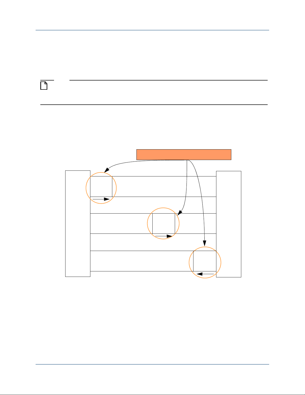
of information as Figure 1-1 illustrates.
Figure 1-1. Execute Write Transaction
The execute_transaction() task results in the master calling the execute_write_addr_phase()
task followed by the execute_write_data_phase() task as illustrated in Figure 1-2.
Mentor Verification IP AE AXI4-Lite User Guide, V10.3
April 2014
23
Page 24
Mentor VIP Altera Edition
Master
interface
Slave
interface
Write
data
Write response channel
Write data channel
Write address channel
Write
response
Address
and
control
get_write_response_phase() - Master
execute_write_data_phase() - Master
execute_write_addr_phase() - Master
AXI4-Lite Transactions
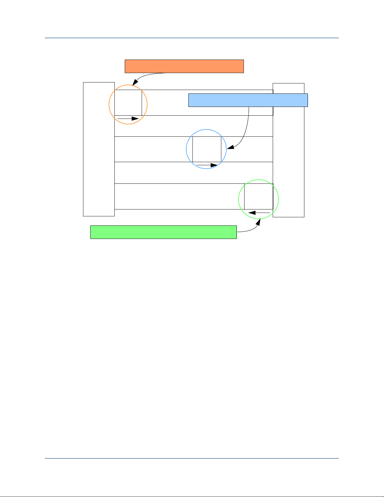
Figure 1-2. Master Write Transaction Phases
The master then calls the get_write_response_phase() task to receive the response from the
slave and to complete its role in the write transaction.
The slave also creates a transaction by calling the create_slave_transaction() task to accept the
transfer of information from the master. The address phase and data phase are received by the
slave calling the get_write_addr_phase() task, followed by the get_write_data_phase() task as
illustrated in Figure 1-3.
24
Mentor Verification IP AE AXI4-Lite User Guide, V10.3
April 2014
Page 25
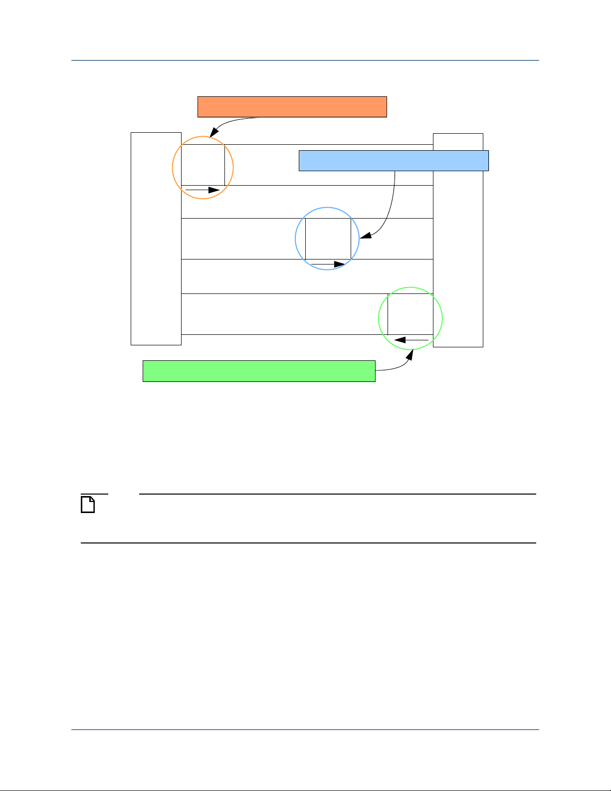
Figure 1-3. Slave Write Transaction Phases
Note
Master
interface
Slave
interface
Write
data
Write response channel
Write data channel
Write address channel
Write
response
Address
and
control
execute_write_response_phase() - Slave
get_write_data_phase() - Slave
get_write_addr_phase() - Slave
Mentor VIP Altera Edition
AXI4-Lite Transactions
The slave then executes a write response phase by calling the execute_write_response_phase()
task and completes its role in the write transaction.
AXI Read Transaction Master and Slave Roles
The following description of a read transaction references the SystemVerilog BFM API
tasks. There are equivalent VHDL BFM API procedures that perform the same
functionality.
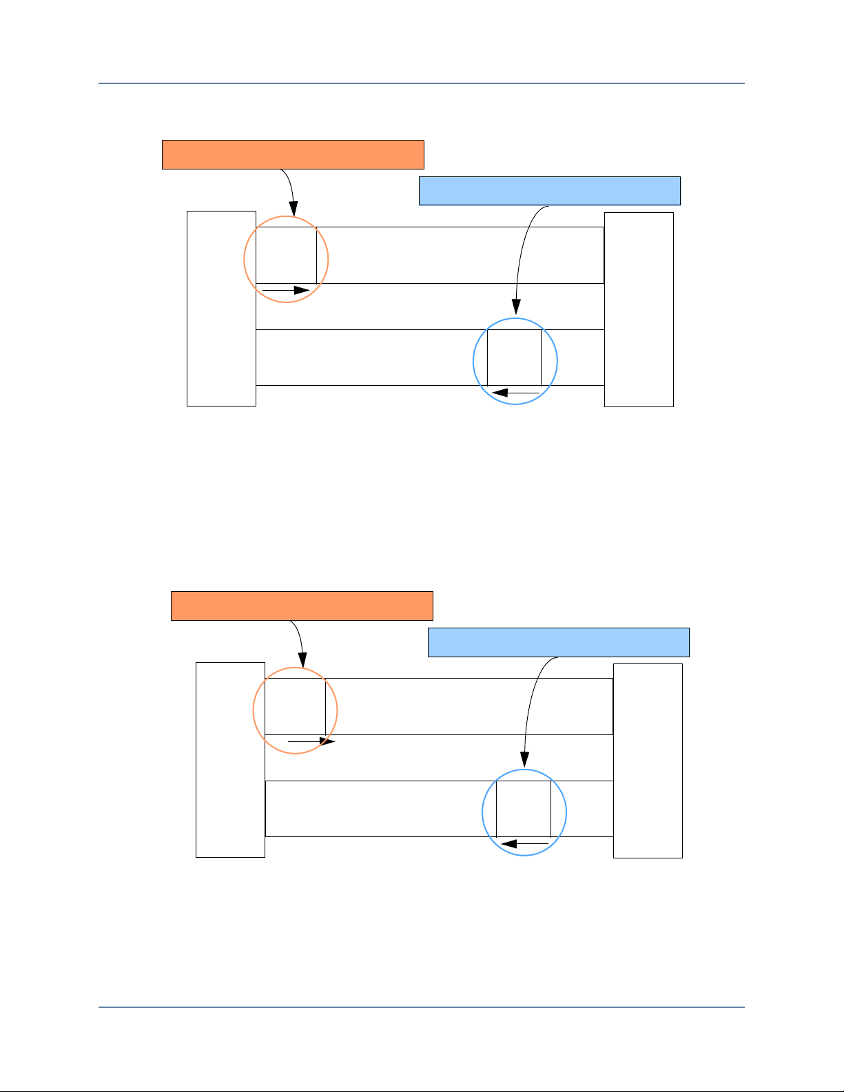
A read transaction is similar to a write transaction. The master initiates the read by calling the
create_read_transaction() and execute_transaction() tasks. The execute_transaction() calls the
the execute_read_addr_phase() task followed by the get_read_data_phase() task as illustrated
in Figure 1-4.
Mentor Verification IP AE AXI4-Lite User Guide, V10.3
April 2014
25
Page 26
Mentor VIP Altera Edition
Read
data
Read data channel
Master
interface
Slave
interface
Read address channel
Address
and
control
execute_read_addr_phase() - Master
get_read_data_phase() - Master
Read
data
Read data channel
Master
interface
Slave
interface
Read address channel
Address
and
control
get_read_addr_phase() - Slave
execute_read_data_phase() - Slave
AXI4-Lite Transactions
Figure 1-4. Master Read Transaction Phases
The slave creates a read transaction by calling the create_slave_transaction() task to accept the
transfer of read information from the master. The slave accepts the address phase by calling the
get_read_addr_phase() task, and then executes the data burst phase by calling the
execute_read_data_phase() task as illustrated in Figure 1-5.
Figure 1-5. Slave Read Transaction Phases
Mentor Verification IP AE AXI4-Lite User Guide, V10.3
26
April 2014
Page 27
Chapter 2
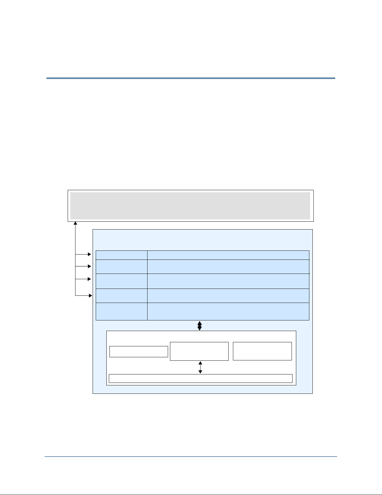
SystemVerilog BFM API
Configuration
Creating
Transaction
Waiting Events
Executing
Transaction
Access
Transaction
create*_transaction
1
set_config/get_config
wait_on
get*_phase
3
Rx_Transaction
queue
queue
Tx_Transaction
Configuration
Wire level
Notes: 1. Refer to create*_transaction()
2. Refer to execute_transaction(), execute*_phase()
3. Refer to get*()
get_rw_transaction/get*_phase
3
get*_addr/get*_data
3
execute_transaction, execute*_phase
2
SystemVerilog interface
Test Program SystemVerilog
SystemVerilog API Overview
This chapter provides the functional description of the SystemVerilog (SV) Application
Programming Interface (API) for all BFM (master, slave, and monitor) components. For each
BFM, you can configure the protocol transaction fields that are executed on the protocol signals,
as well as control the operational transaction fields that permit delays to be introduced between
the handshake signals for each of the five address, data, and response channels.
In addition, each BFM API has tasks that wait for certain events to occur on the system clock
and reset signals, and tasks to get and set information about a particular transaction.
Figure 2-1. SystemVerilog BFM Internal Structure
Mentor Verification IP AE AXI4-Lite User Guide, V10.3
April 2014
27
Page 28

SystemVerilog API Overview
Configuration
Configuration
Configuration sets timeout delays, error reporting, and other attributes of the BFM. Each BFM
has a set_config() function that sets the configuration of the BFM. Refer to the individual BFM
APIs for details.
Each BFM also has a get_config() function that returns the configuration of the BFM. Refer to
the individual BFM APIs for details.
set_config()
The following test program code sets the burst timeout factor for a transaction in the master
BFM.
// Setting the burst timeoutfactor to 1000
master_bfm.set_config(AXI4_CONFIG_BURST_TIMEOUT_FACTOR, 1000);
get_config()
The following test program code gets the protocol signal hold time in the master BFM.
// Getting hold time value
hold_time = master_bfm.get_config(AXI4_CONFIG_HOLD_TIME);
Creating Transactions
To transfer information between a master BFM and a slave DUT over the protocol signals, you
must create a transaction in the master test program. Similarly, to transfer information between
a master DUT and a slave BFM, you must create a transaction in the slave test program. To
monitor the transfer of information using a monitor BFM, you must create a transaction in the
monitor test program.
When you create a transaction, a Transaction Record is created and exists for the life of the
transaction. This transaction record can be accessed by the BFM test programs during the life of
the transaction as it transfers information between the master and slave.
Transaction Record
The transaction record contains two types of transaction fields, protocol and operational, that
either transfer information over the protocol signals or define how and when a transfer occurs.
Protocol fields contain transaction information that is transferred over protocol signals. For
example, the prot field is transferred over the AWPROT protocol signals during a write
transaction.
28
Mentor Verification IP AE AXI4-Lite User Guide, V10.3
April 2014
Page 29

SystemVerilog API Overview
Note
Creating Transactions
Operational fields define how and when the transaction is transferred. Their content is not
transferred over protocol signals. For example, the operation_mode field controls the
blocking/nonblocking operation of a transaction, but this information is not transferred over the
protocol signals.
AXI4-Lite Transaction Definition
The transaction record exists as a SystemVerilog class definition in each BFM. Example 2-1
shows the definition of the axi4_transaction class members that form the transaction record.
Example 2-1. AXI4 Transaction Definition
// Global Transaction Class
class axi4_transaction;
// Protocol
axi4_rw_e read_or_write;
bit [((`MAX_AXI4_ADDRESS_WIDTH) - 1):0] addr;
axi4_prot_e prot;
bit [3:0] region; // Not supported in AXI4-Lite
axi4_size_e size; // Not supported in AXI4-Lite
axi4_burst_e burst; // Not supported in AXI4-Lite
axi4_lock_e lock; // Not supported in AXI4-Lite
axi4_cache_e cache; // Not supported in AXI4-Lite
bit [3:0] qos; // Not supported in AXI4-Lite
bit [((`MAX_AXI4_ID_WIDTH) - 1):0] id; // Not supported in AXI4-Lite
bit [7:0] burst_length; // Not supported in AXI4-Lite
bit [((`MAX_AXI4_USER_WIDTH) - 1):0] addr_user; // Not supported in
AXI4-Lite
bit [((((`MAX_AXI4_RDATA_WIDTH > `MAX_AXI4_WDATA_WIDTH) ?
`MAX_AXI4_RDATA_WIDTH : `MAX_AXI4_WDATA_WIDTH)) - 1):0] data_words [];
bit [(((`MAX_AXI4_WDATA_WIDTH / 8)) - 1):0] write_strobes [];
axi4_response_e resp[];
int address_valid_delay;
int data_valid_delay[];
int write_response_valid_delay;
int address_ready_delay;
int data_ready_delay[];
int write_response_ready_delay;
// Housekeeping
bit gen_write_strobes = 1'b1;
axi4_operation_mode_e operation_mode = AXI4_TRANSACTION_BLOCKING;
axi4_write_data_mode_e write_data_mode = AXI4_DATA_AFTER_ADDRESS;
bit data_beat_done[]; // Not supported in AXI4-Lite
bit transaction_done;
...
endclass
This axi4_transaction class code is shown for information only. Access to each
transaction record during its life is performed by various set*() and get*() tasks described
later in this chapter.
Mentor Verification IP AE AXI4-Lite User Guide, V10.3
April 2014
29
Page 30

SystemVerilog API Overview
Creating Transactions
The contents of the transaction record are defined in Table 2-1.
Table 2-1. Transaction Fields
Transaction Field Description
Protocol Transaction Fields
addr A bit vector (the length is equal to the ARADDR/AWADDR
signal bus width) containing the starting address of the first
transfer (beat) of a transaction. The addr value is transferred
over the ARADDR or AWADDR signals for a read or write
transaction, respectively.
prot An enumeration containing the protection type of a transaction.
The types of protection are:
AXI4_NORM_SEC_DATA (default)
AXI4_PRIV_SEC_DATA
AXI4_NORM_NONSEC_DATA
AXI4_PRIV_NONSEC_DATA
AXI4_NORM_SEC_INST
AXI4_PRIV_SEC_INST
AXI4_NORM_NONSEC_INST
AXI4_PRIV_NONSEC_INST
The prot value is transferred over the ARPROT or AWPROT
signals for a read or write transaction, respectively.
data_words A bit vector (of length equal to the greater of the
RDATA/WDATA signal bus widths) to hold the data words of
the payload. A data_words is transferred over the RDATA or
WDATA signals per beat of the read or write data channel,
respectively.
write_strobes A bit vector (of length equal to the WDATA signal bus width
divided by 8) to hold the write strobes. A write_strobes is
transferred over the WSTRB signals per beat of the write data
channel.
resp An enumeration to hold the response of a transaction. The types
of response are:
AXI4_OKAY;
AXI4_SLVERR;
AXI4_DECERR;
A resp is transferred over the RRESP signals per beat of the
read data channel, and over the BRESP signals for a write
transaction, respectively.
30
Mentor Verification IP AE AXI4-Lite User Guide, V10.3
April 2014
Page 31

SystemVerilog API Overview
Creating Transactions
Table 2-1. Transaction Fields (cont.)
Transaction Field Description
Operational Transaction Fields
read_or_write An enumeration to hold the read or write control flag. The
types of read_or_write are:
AXI4_TRANS_READ
AXI4_TRANS_WRITE
address_valid_delay An integer to hold the delay value of the address channel
AWVALID and ARVALID signals (measured in ACLK
cycles) for a read or write transaction, respectively.
data_valid_delay An integer to hold the delay value of the data channel WVALID
and RVALID signals (measured in ACLK cycles) for a read or
write transaction, respectively.
write_response_valid_delay An integer to hold the delay value of the write response channel
BVALID signal (measured in ACLK cycles) for a write
transaction.
address_ready_delay An integer to hold the delay value of the address channel
AWREADY and ARREADY signals (measured in ACLK
cycles) for a read or write transaction, respectively.
data_ready_delay An integer to hold the delay value of the data channel
WREADY and RREADY signals (measured in ACLK cycles)
for a read or write transaction, respectively.
write_response_ready_delay An integer to hold the delay value of the write response channel
BREADY signal (measured in ACLK cycles) for a write
transaction.
gen_write_strobes Automatically correct write strobes flag. Refer to Automatic
Generation of Byte Lane Strobes for details.
operation_mode An enumeration to hold the operation mode of the transaction.
The two types of operation_mode are:
AXI4_TRANSACTION_NON_BLOCKING
AXI4_TRANSACTION_BLOCKING
write_data_mode An enumeration to hold the write data mode control flag. The
types of write_data_mode are:
AXI4_DATA_AFTER_ADDRESS
AXI4_DATA_WITH_ADDRESS
transaction_done A bit to hold the done flag for a transaction when it has
completed.
Mentor Verification IP AE AXI4-Lite User Guide, V10.3
April 2014
31
Page 32

SystemVerilog API Overview
Note
Creating Transactions
The master BFM API allows you to create a master transaction by providing only the address
argument for a read or write transaction. All other protocol transaction fields automatically
default to legal protocol values to create a complete master transaction record. Refer to the
create_read_transaction() and create_write_transaction() functions for default protocol read
and write transaction field values.
The slave BFM API allows you to create a slave transaction without providing any arguments.
All protocol transaction fields automatically default to legal protocol values to create a complete
slave transaction record. Refer to the create_slave_transaction() function for default protocol
transaction field values.
The monitor BFM API allows you to create a monitor transaction without providing any
arguments. All protocol transaction fields automatically default to legal protocol values to
create a complete slave transaction record. Refer to the create_monitor_transaction() function
for default protocol transaction field values.
If you change the default value of a protocol transaction field, this value is valid for all
future transactions until you set a new value.
create*_transaction()
There are two master BFM API functions available to create transactions,
create_read_transaction() and create_write_transaction(), a create_slave_transaction() for the
slave BFM API, and a create_monitor_transaction() for the monitor BFM API.
For example, the following master BFM test program creates a simple write transaction with a
start address of 1, and a single data phase with a data value of 2, the master BFM test program
would contain the following code:
// Define a variable trans of type axi4_transaction
axi4_transaction write_trans;
// Create master write transaction
write_trans = bfm.create_write_transaction(1);
write_trans.data_words = 2;
For example, to create a simple slave transaction, the slave BFM test program contains the
following code:
// Define a variable slave_trans of type axi4_transaction
axi4_transaction slave_trans;
// Create slave transaction
slave_trans = bfm.create_slave_transaction();
32
Mentor Verification IP AE AXI4-Lite User Guide, V10.3
April 2014
Page 33

SystemVerilog API Overview
Executing Transactions
Executing Transactions
Executing a transaction in a master/slave BFM test program initiates the transaction onto the
protocol signals. Each master/slave BFM API has execution tasks that push transactions into the
BFM internal transaction queues. Figure 2-1 on page 27 illustrates the internal BFM structure.
execute_transaction(), execute*_phase()
If the DUT is a slave, then the execute_transaction() task is called in the master BFM test
program. If the DUT is a master, then the execute*_phase() task is called in the slave BFM test
program.
For example, to execute a master write transaction the master BFM test program contains the
following code:
// By default the execution of a transaction will block
bfm.execute_transaction(write_trans);
For example, to execute a slave write response phase, the slave BFM test program contains the
following code:
// By default the execution of a transaction will block
bfm.execute_write_response_phase(slave_trans);
Waiting Events
Each BFM API has tasks that block the test program code execution until an event has occurred.
The wait_on() task blocks the test program until an ACLK or ARESETn signal event has
occurred before proceeding.
The get*_transaction(), get*_phase(), get*_cycle() tasks block the test program code execution
until a complete transaction, phase, or cycle has occurred, respectively.
wait_on()
A BFM test program can wait for the positive edge of the ARESETn signal using the following
code:
// Block test program execution until the positive edge of the clock
bfm.wait_on(AXI4_RESET_POSEDGE);
Mentor Verification IP AE AXI4-Lite User Guide, V10.3
April 2014
33
Page 34

SystemVerilog API Overview
Note
Note
Access Transaction Record
get*_transaction(), get*_phase(), get*_cycle()
A slave BFM test program can use a received write address phase to form the response to the
write transaction. The test program gets the write address phase for the transaction by calling
the get_write_addr_phase() task. This task blocks until it has received the address phase,
allowing the test program to call the execute_write_response_phase() task for the transaction at
a later stage, as shown in the slave BFM test program in Example 2-2.
Example 2-2. Slave Test Program Using get_write_addr_phase()
slave_trans = bfm.create_slave_transaction();
bfm.get_write_addr_phase(slave_trans);
...
bfm.execute_write_response_phase(slave_trans);
Not all BFM APIs support the full complement of get*_transaction(), get*_phase(),
get*_cycle() tasks. Refer to the individual master, slave, or monitor BFM API for details.
Access Transaction Record
Each BFM API has tasks that can access a complete or partially complete Transaction Record.
The set*() and get*() tasks are used in a test program to set and get information from the
transaction record.
The set*() and get*() tasks are not explicitly described in each BFM API chapter. The
simple rule for the task name is set_ or get_ followed by the name of the transaction field
accessed. Refer to “Transaction Fields” on page 30 for transaction field name details.
set*()
For example, to set the WSTRB write strobes signal in the Transaction Record of a write
transaction, the master test program would use the set_write_strobes() task, as shown in the
following code:
write_trans.set_write_strobes(4'b0010);
get*()
For example, a slave BFM test program uses a received write address phase to get the
AWPROT signal value from the Transaction Record, as shown in the following slave BFM test
program code:
34
Mentor Verification IP AE AXI4-Lite User Guide, V10.3
April 2014
Page 35

SystemVerilog API Overview
Operational Transaction Fields
// Define a variable prot_value of type axi4_transaction
axi4_prot_e prot_value;
slave_trans = bfm.create_slave_transaction();
// Wait for a write address phase
bfm.get_write_addr_phase(slave_trans);
... …
// Get the AWPROT signal value of the slave transaction
prot_value = bfm.get_prot(slave_trans);
Operational Transaction Fields
Operational transaction fields control the way a transaction is executed onto the protocol
signals. They also indicate when a data phase (beat) or transaction is complete.
Automatic Generation of Byte Lane Strobes
The master BFM permits unaligned and narrow write transfers by using byte lane strobe
(WSTRB) signals to indicate which byte lanes contain valid data per data phase (beat).
When you create a write transaction in your master BFM test program, the write_strobes
variable is available to store the write strobe values for the write data phase (beat) in the
transaction. To assist you in creating the correct byte lane strobes, automatic correction of any
previously set write_strobes is performed by default during execution of the write transaction,
or write data phase (beat). You can disable this default behavior by setting the operational
transaction field gen_write_strobes = 0, which allows any previously set write_strobes to pass
through uncorrected onto the protocol WSTRB signals. In this mode, with the automatic
correction disabled, you are responsible for setting the correct write_strobes for the whole
transaction.
The automatic correction algorithm performs a bit-wise AND operation on any previously set
write_strobes. To do the corrections, the correction algorithm uses the equations described in
the AMBA AXI Protocol Specification, Section A3.4.1, that define valid write data byte lanes
for legal protocol. Therefore, if you require automatic generation of all write_strobes, before the
write transaction executes, you must set all write_strobes to 1, indicating that all bytes lanes
initially contain valid write data prior to the execution of the write transaction. Automatic
correction then sets the relevant write_strobes to 0 to produce legal protocol WSTRB signals.
Operation Mode
By default, each read or write transaction performs a blocking operation which prevents a
following transaction from starting until the current active transaction completes.
Mentor Verification IP AE AXI4-Lite User Guide, V10.3
April 2014
35
Page 36

SystemVerilog API Overview
Operational Transaction Fields
You can configure this behavior to be nonblocking by setting the operation_mode transaction
field to the enumerate type value AXI4_TRANSACTION_NON_BLOCKING instead of the
default AXI4_TRANSACTION_BLOCKING.
For example, in a master BFM test program you create a transaction by calling the
create_read_transaction() or create_write_transaction() tasks, which creates a transaction
record. Before executing the transaction record, you can change the operation_mode as follows:
// Create a write transaction to create a transaction record
trans = bfm.create_write_transaction(1);
// Change operation_mode to be nonblocking in the transaction record
trans.operation_mode(AXI4_TRANSACTION_NON_BLOCKING);
Channel Handshake Delay
Each of the five protocol channels have *VALID and *READY handshake signals that control
the rate at which information is transferred between a master and slave. Refer to the Handshake
Delay for details of the AXI4-Lite BFM API.
Handshake Delay
The delay between the *VALID and *READY handshake signals for each of the five protocol
channels is controlled in a BFM test program using execute_*_ready(), get_*_ready(), and
get_*_cycle() tasks. The execute_*_ready() tasks place a value onto the *READY signals and
the get_*_ready() tasks retrieve a value from the *READY signals. The get_*_cycle() tasks
wait for a *VALID signal to be asserted and are used to insert a delay between the *VALID and
*READY signals in the BFM test program.
For example, the master BFM test program code below inserts a specified delay between the
read channel RVALID and RREADY handshake signals using the execute_read_data_ready()
and get_read_data_cycle() tasks.
// Set the RREADY signal to ‘0’ so that it is nonblocking
fork
bfm.execute_read_data_ready(1'b0);
join_none
// Wait until the RVALID signal is asserted and then wait_on the specified
// number of ACLK cycles
bfm.get_read_data_cycle;
repeat(5) bfm.wait_on(AXI4_CLOCK_POSEDGE);
// Set the RREADY signal to ‘1’ so that it blocks for an ACLK cycle
bfm.execute_read_data_ready(1'b1);
36
Mentor Verification IP AE AXI4-Lite User Guide, V10.3
April 2014
Page 37

SystemVerilog API Overview
Operational Transaction Fields
VALID Signal Delay Transaction Fields
The transaction record contains a *_valid_delay transaction field for each of the five protocol
channels to configure the delay value prior to the assertion of the *VALID signal for the
channel. The master BFM holds the delay configuration for the *VALID signals that it asserts,
and the slave BFM holds the delay configuration for the *VALID signals that it asserts.
Table 2-2 specifies which *_valid_delay fields are configured by the master and slave BFMs.
Table 2-2. Master and Slave *_valid_delay Configuration Fields
Signal Operational Transaction Field Configuration BFM
AWVALID address_valid_delay Master
WVALID data_valid_delay Master
BVALID write_response_valid_delay Slave
ARVALID address_valid_delay Master
RVALID data_valid_delay Slave
*READY Handshake Signal Delay Transaction Fields
The transaction record contains a *_ready_delay transaction field for each of the five protocol
channels to store the delay value that occurred between the assertion of the *VALID and
*READY handshake signals for the channel. Table 2-3 specifies the *_ready_delay field
corresponding to the *READY signal delay.
Table 2-3. Master and Slave *_ready_delay Transaction Fields
Signal Operational Transaction Field
AWREADY address_ready_delay
WREADY data_ready_delay
BREADY write_response_ready_delay
ARREADY address_ready_delay
RREADY data_ready_delay
Transaction Done
The transaction_done field in each transaction indicates when the transaction is complete.
In a master BFM test program, you call the get_read_data_phase() task to investigate whether a
read transaction is complete, and the get_write_response_phase() to investigate whether a write
transaction is complete.
Mentor Verification IP AE AXI4-Lite User Guide, V10.3
April 2014
37
Page 38

SystemVerilog API Overview
Operational Transaction Fields
38
Mentor Verification IP AE AXI4-Lite User Guide, V10.3
April 2014
Page 39

Chapter 3
SystemVerilog Master BFM
This chapter provides information about the SystemVerilog master BFM. Each BFM has an
API that contains tasks and functions to configure the BFM and to access the dynamic
Transaction Record during the lifetime of the transaction.
Master BFM Protocol Support
The AXI4-Lite master BFM supports the AMBA AXI4-Lite protocol with restrictions described
in “Protocol Restrictions” on page 17.
Master Timing and Events
For detailed timing diagrams of the protocol bus activity, refer to the relevant AMBA AXI
Protocol Specification chapter, which you can use to reference details of the following master
BFM API timing and events.
The AMBA AXI Protocol Specification does not define any timescale or clock period with
signal events sampled and driven at rising ACLK edges. Therefore, the master BFM does not
contain any timescale, timeunit, or timeprecision declarations with the signal setup and hold
times specified in units of simulator time-steps.
The simulator time-step resolves to the smallest of all the time-precision declarations in the test
bench and design IP as a result of these directives, declarations, options, or initialization files:
• ` timescale directives in design elements
• Timeprecision declarations in design elements
• Compiler command-line options
• Simulation command-line options
• Local or site-wide simulator initialization files
If there is no timescale directive, the default time unit and time precision are tool specific. The
recommended practice is to use timeunit and timeprecision declarations. For details, refer to
Section 3.14, “System Time Units and Precision,” of the IEEE Standard for
SystemVerilog—Unified Hardware Design, Specification, and Verification Language, IEEE Std
1800™-2012 , February 21, 2013. This user guide refers to this document as the IEEE Standard
for SystemVerilog.
Mentor Verification IP AE AXI4-Lite User Guide, V10.3
April 2014
39
Page 40

SystemVerilog Master BFM
Master BFM Configuration
Master BFM Configuration
A master BFM supports the full range of signals defined for the AMBA AXI Protocol
Specification. It has parameters that configure the widths of the address and data signals, and
transaction fields to specify timeout factors, setup and hold times, and so on.
You can change the address and data signal widths from their default settings by assigning them
new values, usually in the top-level module of the test bench. These new values are then passed
to the master BFM using a parameter port list of the master BFM module. For example, the code
extract below shows the master BFM with the address and data signal widths defined in module
top() and passed to the master_test_program parameter port list:
module top ();
parameter AXI4_ADDRESS_WIDTH = 24;
parameter AXI4_RDATA_WIDTH = 16;
parameter AXI4_WDATA_WIDTH = 16;
master_test_program #(AXI4_ADDRESS_WIDTH, AXI4_RDATA_WIDTH,
AXI4_WDATA_WIDTH) bfm_master(....);
Table 3-1 lists parameter names for the address, data signals, etc, and their default values.
Table 3-1. Master BFM Signal Width Parameters
Signal Width Parameter Description
AXI4_ADDRESS_WIDTH Address signal width in bits. This applies to the ARADDR
and AWADDR signals. Refer to the AMBA AXI Protocol
Specification for more details. Default: 32.
AXI4_RDATA_WIDTH Read data signal width in bits. This applies to the RDATA
signals. Refer to the AMBA AXI Protocol Specification for
more details. Default: 64.
AXI4_WDATA_WIDTH Write data signal width in bits. This applies to the WDATA
signals. Refer to the AMBA AXI Protocol Specification for
more details. Default: 64.
index Ignored for the SystemVerilog master BFM.
READ_ISSUING_
CAPABILITY
The maximum number of outstanding read transactions that
can be issued from the master BFM. This parameter is set
with the Qsys Parameter Editor. See “Running the Qsys
Tool” on page 356. for details.
Default: 16.
40
Mentor Verification IP AE AXI4-Lite User Guide, V10.3
April 2014
Page 41

Table 3-1. Master BFM Signal Width Parameters (cont.)
Signal Width Parameter Description
SystemVerilog Master BFM
Master BFM Configuration
WRITE_ISSUING_
CAPABILITY
The maximum number of outstanding write transactions that
can be issued from the master BFM. This parameter is set
with the Qsys Parameter Editor. See “Running the Qsys
Tool” on page 356. for details.
Default: 16.
COMBINED_ISSUING_
CAPABILITY
The maximum number of outstanding combined read and
write transactions that can be issued from the master BFM.
This parameter is set with the Qsys Parameter Editor. See
“Running the Qsys Tool” on page 356. for details.
Default: 16.
A master BFM has configuration fields that you can set with the set_config() function to
configure timeout factors, and setup and hold times, and so on. You can also get the value of a
configuration field using the get_config() function. Table 3-2 describes the full list of
configuration fields.
Table 3-2. Master BFM Configuration
Configuration Field Description
Timing Variables
AXI4_CONFIG_SETUP_TIME The setup-time prior to the active edge
of ACLK, in units of simulator timesteps for all signals.1 Default: 0.
AXI4_CONFIG_HOLD_TIME The hold-time after the active edge of
ACLK, in units of simulator time-steps
for all signals.1 Default: 0.
AXI4_CONFIG_MAX_TRANSACTION_TIME_
FACTOR
The maximum timeout duration for a
read/write transaction in clock cycles.
Default: 100000.
AXI4_CONFIG_BURST_TIMEOUT_FACTOR The maximum delay between the
individual phases of a read/write
transaction in clock cycles. Default:
10000.
AXI4_CONFIG_MAX_LATENCY_AWVALID_
ASSERTION_TO_AWREADY
The maximum timeout duration from
the assertion of AWVALID to the
assertion of AWREADY in clock
periods. Default: 1000.
AXI4_CONFIG_MAX_LATENCY_ARVALID_
ASSERTION_TO_ARREADY
The maximum timeout duration from
the assertion of ARVALID to the
assertion of ARREADY in clock
periods. Default: 10000.
Mentor Verification IP AE AXI4-Lite User Guide, V10.3
April 2014
41
Page 42

SystemVerilog Master BFM
Master Assertions
Table 3-2. Master BFM Configuration (cont.)
Configuration Field Description
AXI4_CONFIG_MAX_LATENCY_RVALID_
ASSERTION_TO_RREADY
The maximum timeout duration from
the assertion of RVALID to the
assertion of RREADY in clock periods.
Default: 10000.
AXI4_CONFIG_MAX_LATENCY_BVALID_
ASSERTION_TO_BREADY
The maximum timeout duration from
the assertion of BVALID to the
assertion of BREADY in clock periods.
Default: 10000.
AXI4_CONFIG_MAX_LATENCY_WVALID_
ASSERTION_TO_WREADY
The maximum timeout duration from
the assertion of WVALID to the
assertion of WREADY in clock
periods. Default 10000.
Master Attributes
AXI4_CONFIG_AXI4LITE_axi4 Configures the AXI4 master BFM to be
AXI4-Lite compatible.
0 = disabled (default)
1 = enabled
Slave Attributes
AXI4_CONFIG_SLAVE_START_ADDR Configures the start address map for
the slave.
AXI4_CONFIG_SLAVE_END_ADDR Configures the end address map for the
slave.
Error Detection
AXI4_CONFIG_ENABLE_ALL_ASSERTIONS Global enable/disable of all assertion
checks in the BFM.
0 = disabled
1 = enabled (default)
AXI4_CONFIG_ENABLE_ASSERTION Individual enable/disable of assertion
check in the BFM.
0 = disabled
1 = enabled (default)
1.
Refer to Master Timing and Events for details of simulator time-steps.
Master Assertions
Each master BFM performs protocol error checking using the built-in assertions.
42
Mentor Verification IP AE AXI4-Lite User Guide, V10.3
April 2014
Page 43

SystemVerilog Master BFM
Note
Note
SystemVerilog Master API
The built-in BFM assertions are independent of programming language and simulator.
Assertion Configuration
By default, all built-in assertions are enabled in the master AXI4-Lite BFM. To globally disable
them in the master BFM, use the set_config() command as the following example illustrates:
set_config(AXI4_CONFIG_ENABLE_ALL_ASSERTIONS,0)
Alternatively, you can disable individual built-in assertions by using a sequence of get_config()
and set_config() commands on the respective assertion. For example, to disable assertion
checking for the AWADDR signal changing between the AWVALID and AWREADY
handshake signals, use the following sequence of commands:
// Define a local bit vector to hold the value of the assertion bit vector
bit [255:0] config_assert_bitvector;
// Get the current value of the assertion bit vector
config_assert_bitvector = bfm.get_config(AXI4_CONFIG_ENABLE_ASSERTION);
// Assign the AXI4_AWADDR_CHANGED_BEFORE_AWREADY assertion bit to 0
config_assert_bitvector[AXI4_AWADDR_CHANGED_BEFORE_AWREADY] = 0;
// Set the new value of the assertion bit vector
bfm.set_config(AXI4_CONFIG_ENABLE_ASSERTION, config_assert_bitvector);
Do not confuse the AXI4_CONFIG_ENABLE_ASSERTION bit vector with the
AXI4_CONFIG_ENABLE_ALL_ASSERTIONS global enable/disable.
To re-enable the AXI4_AWADDR_CHANGED_BEFORE_AWREADY assertion, follow the
above code sequence and assign the assertion within the
AXI4_CONFIG_ENABLE_ASSERTION bit vector to 1.
For a complete listing of AXI4-Lite assertions, refer to “AXI4-Lite Assertions” on page 369.
SystemVerilog Master API
This section describes the SystemVerilog master API.
Mentor Verification IP AE AXI4-Lite User Guide, V10.3
April 2014
43
Page 44

SystemVerilog Master BFM
set_config()
set_config()
This function sets the configuration of the master BFM.
Prototype
Arguments
Returns
function void set_config
(
input axi4_config_e config_name,
input axi4_max_bits_t config_val
);
config_name Configuration name:
AXI4_CONFIG_SETUP_TIME
AXI4_CONFIG_HOLD_TIME
AXI4_CONFIG_MAX_TRANSACTION_TIME_FACTOR
AXI4_CONFIG_AXI4LITE_axi4
AXI4_CONFIG_ENABLE_ALL_ASSERTIONS
AXI4_CONFIG_ENABLE_ASSERTION
AXI4_CONFIG_MAX_LATENCY_AWVALID_ASSERTION_
TO_AWREADY
AXI4_CONFIG_MAX_LATENCY_ARVALID_ASSERTION_
TO_ARREADY
AXI4_CONFIG_MAX_LATENCY_RVALID_ASSERTION_
TO_RREADY
AXI4_CONFIG_MAX_LATENCY_BVALID_ASSERTION_
TO_BREADY
AXI4_CONFIG_MAX_LATENCY_WVALID_ASSERTION_
TO_WREADY
AXI4_CONFIG_SLAVE_START_ADDR
AXI4_CONFIG_SLAVE_END_ADDR
See “Master BFM Configuration” on page 40 for descriptions and valid
values.
None
Example
set_config(AXI4_CONFIG_MAX_TRANSACTION_TIME_FACTOR, 1000);
44
Mentor Verification IP AE AXI4-Lite User Guide, V10.3
April 2014
Page 45

get_config()
This function gets the configuration of the master BFM.
SystemVerilog Master BFM
get_config()
Prototype
Arguments
Returns
function void get_config
(
input axi4_config_e config_name,
);
config_name Configuration name:
AXI4_CONFIG_SETUP_TIME
AXI4_CONFIG_HOLD_TIME
AXI4_CONFIG_MAX_TRANSACTION_TIME_FACTOR
AXI4_CONFIG_AXI4LITE_axi4
AXI4_CONFIG_ENABLE_ALL_ASSERTIONS
AXI4_CONFIG_ENABLE_ASSERTION
AXI4_CONFIG_MAX_LATENCY_AWVALID_ASSERTION_
TO_AWREADY
AXI4_CONFIG_MAX_LATENCY_ARVALID_ASSERTION_
TO_ARREADY
AXI4_CONFIG_MAX_LATENCY_RVALID_ASSERTION_
TO_RREADY
AXI4_CONFIG_MAX_LATENCY_BVALID_ASSERTION_
TO_BREADY
AXI4_CONFIG_MAX_LATENCY_WVALID_ASSERTION_
TO_WREADY
AXI4_CONFIG_SLAVE_START_ADDR
AXI4_CONFIG_SLAVE_END_ADDR
config_val See “Master BFM Configuration” on page 40 for descriptions and valid
values.
Example
get_config(AXI4_CONFIG_MAX_TRANSACTION_TIME_FACTOR);
Mentor Verification IP AE AXI4-Lite User Guide, V10.3
April 2014
45
Page 46

SystemVerilog Master BFM
create_write_transaction()
create_write_transaction()
This nonblocking function creates a write transaction with a start address addr argument. All
other transaction fields default to legal protocol values, unless previously assigned a value. It
returns with the axi4_transaction record.
Prototype
Arguments
Protocol
Transaction
Fields
Operational
Transaction
Fields
Operational
Transaction
Fields
Returns
function automatic axi4_transaction create_write_transaction
(
input bit [((AXI4_ADDRESS_WIDTH) - 1):0] addr);
addr Start address
prot Protection:
AXI4_NORM_SEC_DATA; (default)
AXI4_PRIV_SEC_DATA;
AXI4_NORM_NONSEC_DATA;
AXI4_PRIV_NONSEC_DATA;
AXI4_NORM_SEC_INST;
AXI4_PRIV_SEC_INST;
AXI4_NORM_NONSEC_INST;
AXI4_PRIV_NONSEC_INST;
data_words Data words.
write_strobes Write strobes:
Each strobe 0 or 1.
resp Burst response:
AXI4_OKAY;
AXI4_SLVERR;
AXI4_DECERR;
gen_write_strobes Generate write strobes flag:
operation_mode Operation mode:
write_data_mode Write data mode:
address_valid_delay Address channel AWVALID delay measured in ACLK cycles for
data_valid_delay Write data channel WVALID delay measured in ACLK cycles for
write_response_
ready_delay
transaction_done Write transaction done flag for this transaction.
The axi4_transaction record.
0 = user supplied write strobes.
1 = auto-generated write strobes (default).
AXI4_TRANSACTION_NON_BLOCKING;
AXI4_TRANSACTION_BLOCKING; (default)
AXI4_DATA_AFTER_ADDRESS; (default)
AXI4_DATA_WITH_ADDRESS;
this transaction (default = 0).
this transaction (default = 0).
Write response channel BREADY delay measured in ACLK
cycles for this transaction (default = 0).
46
Mentor Verification IP AE AXI4-Lite User Guide, V10.3
April 2014
Page 47

SystemVerilog Master BFM
create_write_transaction()
Example
// Create a write transaction to start address 16.
trans = bfm.create_write_transaction(16);
trans.set_data_words = ('hACE0ACE1, 0); //Note: array element 0.
Mentor Verification IP AE AXI4-Lite User Guide, V10.3
April 2014
47
Page 48

SystemVerilog Master BFM
create_read_transaction()
create_read_transaction()
This nonblocking function creates a read transaction with a start address addr. All other
transaction fields default to legal AXI4-Lite protocol values, unless previously assigned a value.
It returns the axi4_transaction record.
Prototype
Arguments
Protocol
Transaction
Fields
Operational
Transaction
Fields
function automatic axi4_transaction create_read_transaction
(
input bit [((AXI4_ADDRESS_WIDTH) - 1):0] addr
);
addr Start address
prot Protection:
AXI4_NORM_SEC_DATA; (default)
AXI4_PRIV_SEC_DATA;
AXI4_NORM_NONSEC_DATA;
AXI4_PRIV_NONSEC_DATA;
AXI4_NORM_SEC_INST;
AXI4_PRIV_SEC_INST;
AXI4_NORM_NONSEC_INST;
AXI4_PRIV_NONSEC_INST;
data_words Data words.
resp Burst response:
AXI4_OKAY;
AXI4_EXOKAY;
AXI4_SLVERR;
AXI4_DECERR;
operation_mode Operation mode:
AXI4_TRANSACTION_NON_BLOCKING;
AXI4_TRANSACTION_BLOCKING; (default)
address_valid_delay Address channel ARVALID delay measured in ACLK
cycles for this transaction (default = 0).
data_ready_delay Read data channel RREADY delay array measured in
ACLK cycles for this transaction (default = 0).
transaction_done Read transaction done flag for this transaction.
Returns
axi4_transaction The transaction record:
Example
// Read data to start address 16.
trans = bfm.create_read_transaction(16);
48
Mentor Verification IP AE AXI4-Lite User Guide, V10.3
April 2014
Page 49

SystemVerilog Master BFM
execute_transaction()
execute_transaction()
This task executes a master transaction previously created by the create_write_transaction(), or
create_read_transaction(), functions. The transaction can be blocking (default) or nonblocking,
defined by the transaction record operation_mode field.
The results of execute_transaction() for write transactions varies based on how write transaction
fields are set. If the gen_write_strobes transaction field is set, execute_transaction()
automatically corrects any previously set write_strobes. However, if the gen_write_strobes
field is not set, then any previously assigned write_strobes will be passed through onto the
WSTRB protocol signals, which can result in a protocol violation if not correctly set. Refer to
“Automatic Correction of Byte Lane Strobes” on page 146 for more details.
If a write transaction write_data_mode field is set to AXI4_DATA_WITH_ADDRESS,
execute_transaction() calls the execute_write_addr_phase() and execute_write_data_phase()
tasks simultaneously; otherwise, execute_write_data_phase() will be called after
execute_write_addr_phase() so that the write data phase will occur after the write address phase
(default). It will then call the get_write_response_phase() task to complete the write transaction.
For a read transaction, execute_transaction() calls the execute_read_addr_phase() task
followed by the get_read_data_phase() task to complete the read transaction.
Prototype
Arguments
Returns
task automatic execute_transaction
(
axi4_transaction trans
);
trans
None
The axi4_transaction
record.
Example
// Declare a local variable to hold the transaction record.
axi4_transaction read_trans;
// Create a read transaction with start address of 0 and assign
// it to the local read_trans variable.
read_trans = bfm.create_read_transaction(0);
....
// Execute the read_trans transaction.
bfm.execute_transaction(read_trans);
Mentor Verification IP AE AXI4-Lite User Guide, V10.3
April 2014
49
Page 50

SystemVerilog Master BFM
execute_write_addr_phase()
execute_write_addr_phase()
This task executes a master write address phase previously created by the
create_write_transaction() function. This phase can be blocking (default) or nonblocking, as
defined by the transaction operation_mode field.
It sets the AWVALID protocol signal at the appropriate time defined by the transaction
address_valid_delay field.
Prototype
task automatic execute_write_addr_phase
(
axi4_transaction trans
);
Arguments
Returns
trans The axi4_transaction record.
None
Example
// Declare a local variable to hold the transaction record.
axi4_transaction write_trans;
// Create a write transaction with start address of 0 and assign
// it to the local write_trans variable.
write_trans = bfm.create_write_transaction(0);
....
// Execute the write_trans transaction.
bfm.execute_transaction(write_trans);
50
Mentor Verification IP AE AXI4-Lite User Guide, V10.3
April 2014
Page 51

SystemVerilog Master BFM
execute_read_addr_phase()
execute_read_addr_phase()
This task executes a master read address phase previously created by the
create_read_transaction() function. This phase can be blocking (default) or nonblocking, as
defined by the transaction operation_mode field.
It sets the ARVALID protocol signal at the appropriate time, defined by the transaction
address_valid_delay field.
Prototype
task automatic execute_read_addr_phase
(
axi4_transaction trans
);
Arguments
Returns
trans The axi4_transaction record.
None
Example
// Declare a local variable to hold the transaction record.
axi4_transaction read_trans;
// Create a read transaction with start address of 0 and assign
// it to the local read_trans variable.
read_trans = bfm.create_read_transaction(0);
....
// Execute the write_trans transaction.
bfm.execute_transaction(read_trans);
Mentor Verification IP AE AXI4-Lite User Guide, V10.3
April 2014
51
Page 52

SystemVerilog Master BFM
execute_write_data_phase()
execute_write_data_phase()
This task executes a write data phase (beat) previously created by the
create_write_transaction() task. This phase can be blocking (default) or nonblocking, defined
by the transaction record operation_mode field.
The execute_write_data_phase() sets the WVALID protocol signal at the appropriate time
defined by the transaction record data_valid_delay field.
Prototype
task automatic execute_write_data_phase
(
axi4_transaction trans
int index = 0, // Optional
output bit last
);
Arguments
Returns
trans The axi4_transaction record.
index Data phase (beat) number.
Note: ‘0’ for AXI4-Lite
last Flag to indicate that this phase is the last beat of data.
None
Example
// Declare a local variable to hold the transaction record.
axi4lite_transaction write_trans;
// Create a write transaction with start address of 0 and assign
// it to the local write_trans variable.
write_trans = bfm.create_write_transaction(0);
....
// Execute the write data phase for the write_trans transaction.
bfm.execute_write_data_phase(write_trans, 0, last); //Note array element 0
52
Mentor Verification IP AE AXI4-Lite User Guide, V10.3
April 2014
Page 53

SystemVerilog Master BFM
Note
get_read_data_phase()
get_read_data_phase()
This blocking task gets a read data phase previously created by the create_read_transaction()
task.
The get_read_data_phase() sets the RREADY protocol signal at the appropriate time
defined by the data_ready_delay field and sets the transaction_done field to 1 to indicate
the whole read transaction has completed.
Prototype
task automatic get_read_data_phase
(
axi4_transaction trans
int index = 0 // Optional
);
Arguments
Returns
trans The axi4_transaction record.
index (Optional) Data phase (beat) number.
Note: ‘0’ for AXI4-Lite
None
Example
// Declare a local variable to hold the transaction record.
axi4_transaction read_trans;
// Create a read transaction with start address of 0 and assign
// it to the local read_trans variable.
read_trans = bfm.create_read_transaction(0);
....
// Get the read data phase for the read_trans transaction.
bfm.get_read_data_phase(read_trans, 0); //Note: array element 0.
Mentor Verification IP AE AXI4-Lite User Guide, V10.3
April 2014
53
Page 54

SystemVerilog Master BFM
Note
get_write_response_phase()
get_write_response_phase()
This blocking task gets a write response phase previously created by the
create_write_transaction() task.
The get_write_response_phase() sets the transaction_done field to 1 when the
transaction completes to indicate the whole transaction is complete.
Prototype
task automatic get_write_response_phase
(
axi4_transaction trans
);
Arguments
Returns
trans The axi4_transaction record.
None
Example
// Declare a local variable to hold the transaction record.
axi4_transaction write_trans;
// Create a write transaction with start address of 0 and assign
// it to the local write_trans variable.
write_trans = bfm.create_write_transaction(0);
....
// Get the write response phase for the write_trans transaction.
bfm.get_write_response_phase(write_trans);
54
Mentor Verification IP AE AXI4-Lite User Guide, V10.3
April 2014
Page 55

SystemVerilog Master BFM
get_read_addr_ready()
get_read_addr_ready()
This blocking task returns the value of the read address channel ARREADY signal using the
ready argument. It will block for one ACLK period.
Prototype
Arguments
Returns
task automatic get_read_addr_ready
(
output bit ready
);
ready The value of the ARREADY signal.
ready
Example
// Get the ARREADY signal value
bfm.get_read_addr_ready(ready);
Mentor Verification IP AE AXI4-Lite User Guide, V10.3
April 2014
55
Page 56

SystemVerilog Master BFM
get_read_data_cycle()
get_read_data_cycle()
This blocking task waits until the read data channel RVALID signal is asserted.
Prototype
Arguments
Returns
task automatic get_read_data_cycle();
None
None
Example
// Waits until the read data channel RVALID signal is asserted.
bfm.get_read_data_cycle();
56
Mentor Verification IP AE AXI4-Lite User Guide, V10.3
April 2014
Page 57

SystemVerilog Master BFM
get_write_addr_ready()
get_write_addr_ready()
This blocking task returns the value of the write address channel AWREADY signal using the
ready argument. It will block for one ACLK period.
Prototype
Arguments
Returns
task automatic get_write_addr_ready
(
output bit ready
);
ready The value of the AWREADY signal.
None
Example
// Get the value of the AWREADY signal
bfm.get_write_addr_ready();
Mentor Verification IP AE AXI4-Lite User Guide, V10.3
April 2014
57
Page 58

SystemVerilog Master BFM
get_write_data_ready()
get_write_data_ready()
This blocking task returns the value of the write data channel WREADY signal using the ready
argument. It will block for one ACLK period.
Prototype
Arguments
Returns
task automatic get_write_data_ready
(
output bit ready
);
ready The value of the WREADY signal.
None
Example
// Get the value of the WREADY signal
bfm.get_write_data_ready();
58
Mentor Verification IP AE AXI4-Lite User Guide, V10.3
April 2014
Page 59

SystemVerilog Master BFM
get_write_response_cycle()
get_write_response_cycle()
This blocking task waits until the write response channel BVALID signal is asserted.
Prototype
Arguments
Returns
task automatic get_write_response_cycle();
None
None
Example
// Wait until the write response channel BVALID signal is asserted.
bfm.get_write_response_cycle();
Mentor Verification IP AE AXI4-Lite User Guide, V10.3
April 2014
59
Page 60

SystemVerilog Master BFM
execute_read_data_ready()
execute_read_data_ready()
This task executes a read data ready by placing the ready argument value onto the RREADY
signal. It will block for one ACLK period.
Prototype
Arguments
Returns
task automatic execute_read_data_ready
(
bit ready
);
ready The value to be placed onto the RREADY signal
None
Example
// Assert and deassert the RREADY signal
forever begin
bfm.execute_read_data_ready(1'b0);
bfm.wait_on(AXI4_CLOCK_POSEDGE);
bfm.wait_on(AXI4_CLOCK_POSEDGE);
bfm.execute_read_data_ready(1'b1);
bfm.wait_on(AXI4_CLOCK_POSEDGE);
end
60
Mentor Verification IP AE AXI4-Lite User Guide, V10.3
April 2014
Page 61

SystemVerilog Master BFM
execute_write_resp_ready()
execute_write_resp_ready()
This task executes a write response ready by placing the ready argument value onto the
BREADY signal. It will block for one ACLK period.
Prototype
Arguments
Returns
task automatic execute_write_resp_ready
(
bit ready
);
ready The value to be placed onto the BREADY signal
None
Example
// Assert and deassert the BREADY signal
forever begin
bfm.execute_write_resp_ready(1'b0);
bfm.wait_on(AXI4_CLOCK_POSEDGE);
bfm.wait_on(AXI4_CLOCK_POSEDGE);
bfm.execute_write_resp_ready(1'b1);
bfm.wait_on(AXI4_CLOCK_POSEDGE);
end
Mentor Verification IP AE AXI4-Lite User Guide, V10.3
April 2014
61
Page 62

SystemVerilog Master BFM
wait_on()
wait_on()
This blocking task waits for an event(s) on the ACLK or ARESETn signals to occur before
proceeding. An optional count argument waits for the number of events equal to count.
Prototype
task automatic wait_on
(
axi4_wait_e phase,
input int count = 1 //Optional
);
Arguments
Returns
phase Wait for:
AXI4_CLOCK_POSEDGE
AXI4_CLOCK_NEGEDGE
AXI4_CLOCK_ANYEDGE
AXI4_CLOCK_0_TO_1
AXI4_CLOCK_1_TO_0
AXI4_RESET_POSEDGE
AXI4_RESET_NEGEDGE
AXI4_RESET_ANYEDGE
AXI4_RESET_0_TO_1
AXI4_RESET_1_TO_0
count (Optional) Wait for a number of events to occur set by count.
(default = 1)
None
Example
bfm.wait_on(AXI4_RESET_POSEDGE);
bfm.wait_on(AXI4_CLOCK_POSEDGE,10);
62
Mentor Verification IP AE AXI4-Lite User Guide, V10.3
April 2014
Page 63

Chapter 4
SystemVerilog Slave BFM
This chapter describes the SystemVerilog slave BFM. Each BFM has an API that contains tasks
and functions to configure the BFM and to access the dynamic Transaction Record during the
lifetime of the transaction.
Slave BFM Protocol Support
This section defines protocol support for various AXI BFMs. The AXI4-Lite slave BFM
supports the AMBA AXI4-Lite protocol with restrictions described in “Protocol Restrictions”
on page 17.
Slave Timing and Events
For detailed timing diagrams of the protocol bus activity, refer to the relevant AMBA AXI
Protocol Specification chapter, which you can use to reference details of the following slave
BFM API timing and events.
The specification does not define any timescale or clock period with signal events sampled and
driven at rising ACLK edges. Therefore, the slave BFM does not contain any timescale,
timeunit, or timeprecision declarations with the signal setup and hold times specified in units of
simulator time-steps.
The simulator time-step resolves to the smallest of all the time-precision declarations in the test
bench and design IP based on using the directives, declarations, options, and initialization files
below:
• ` timescale directives in design elements
• Timeprecision declarations in design elements
• Compiler command-line options
• Simulation command-line options
• Local or site-wide simulator initialization files
If there is no timescale directive, the default time unit and time precision are tool specific. Using
timeunit and timeprecision declarations are recommended. Refer to the IEEE Standard for
SystemVerilog, Section 3.14 for details.
Mentor Verification IP AE AXI4-Lite User Guide, V10.3
April 2014
63
Page 64

SystemVerilog Slave BFM
Slave BFM Configuration
Slave BFM Configuration
The slave BFM supports the full range of signals defined for the AMBA AXI Protocol
Specification. It has parameters you can use to configure the widths of the address and data
signals, and transaction fields to configure timeout factors, and setup and hold times, and so on.
You can change the address and data signal widths from their default settings by assigning them
with new values, usually performed in the top-level module of the test bench. These new values
are then passed into the slave BFM using a parameter port list of the slave BFM module. For
example, the code extract below shows the slave BFM with the address and data signal widths
defined in module top() and passed in to the slave_test_program parameter port list:
module top ();
parameter AXI4_ADDRESS_WIDTH = 24;
parameter AXI4_RDATA_WIDTH = 16;
parameter AXI4_WDATA_WIDTH = 16;
slave_test_program #(AXI4_ADDRESS_WIDTH, AXI4_RDATA_WIDTH,
AXI4_WDATA_WIDTH) bfm_slave(....);
Table 4-1 lists the parameter names for the address and data signals, and their default values.
Table 4-1. Slave BFM Signal Width Parameters
Signal Width Parameter Description
AXI4_ADDRESS_WIDTH Address signal width in bits. This applies to the
ARADDR and AWADDR signals. Refer to the AMBA
AXI Protocol Specification for more details. Default: 32
AXI4_RDATA_WIDTH Read data signal width in bits. This applies to the
RDATA signals. Refer to the AMBA AXI Protocol
Specification for more details. Default: 64.
AXI4_WDATA_WIDTH Write data signal width in bits. This applies to the
WDATA signals. Refer to the AMBA AXI Protocol
Specification for more details. Default: 64.
index Ignored for the SystemVerilog slave BFM.
READ_ACCEPTANCE_
CAPABILITY
The maximum number of outstanding read transactions
that can be accepted by the slave BFM. This parameter is
set with the Qsys Parameter Editor. See “Running the
Qsys Tool” on page 356. for details.
Default: 16.
64
Mentor Verification IP AE AXI4-Lite User Guide, V10.3
April 2014
Page 65

Table 4-1. Slave BFM Signal Width Parameters (cont.)
Signal Width Parameter Description
SystemVerilog Slave BFM
Slave BFM Configuration
WRITE_ACCEPTANCE_
CAPABILITY
The maximum number of outstanding write transactions
that can be accepted by the slave BFM. This parameter is
set with the Qsys Parameter Editor. See “Running the
Qsys Tool” on page 356. for details.
Default: 16.
COMBINED_ACCEPTANCE_
CAPABILITY
The maximum number of outstanding combined read and
write transactions that can be accepted by the slave BFM.
This parameter is set with the Qsys Parameter Editor. See
“Running the Qsys Tool” on page 356. for details.
Default: 16.
A slave BFM has configuration fields that you can set with the set_config() function to
configure timeout factors, setup and hold times, and so on. You can also get the value of a
configuration field via the get_config() function.
Table 4-2 describes the full list of configuration fields.
Table 4-2. Slave BFM Configuration
Configuration Field Description
Timing Variables
AXI4_CONFIG_SETUP_TIME The setup time prior to the active edge
of ACLK, in units of simulator timesteps for all signals.1 Default: 0.
AXI4_CONFIG_HOLD_TIME The hold-time after the active edge of
ACLK, in units of simulator timesteps for all signals.1 Default: 0.
AXI4_CONFIG_MAX_TRANSACTION_
TIME_FACTOR
The maximum timeout duration for a
read/write transaction in clock cycles.
Default: 100000.
AXI4_CONFIG_BURST_TIMEOUT_
FACTOR
The maximum delay between the
individual phases of a read/write
transaction in clock cycles. Default:
10000.
AXI4_CONFIG_MAX_LATENCY_
AWVALID_ASSERTION_TO_AWREADY
The maximum timeout duration from
the assertion of AWVALID to the
assertion of AWREADY in clock
periods (default 10000).
AXI4_CONFIG_MAX_LATENCY_
ARVALID_ASSERTION_TO_ARREADY
The maximum timeout duration from
the assertion of ARVALID to the
assertion of ARREADY in clock
periods (default 10000).
Mentor Verification IP AE AXI4-Lite User Guide, V10.3
April 2014
65
Page 66

SystemVerilog Slave BFM
Slave BFM Configuration
Table 4-2. Slave BFM Configuration (cont.)
Configuration Field Description
AXI4_CONFIG_MAX_LATENCY_RVALID_
ASSERTION_TO_RREADY
The maximum timeout duration from
the assertion of RVALID to the
assertion of RREADY in clock
periods (default 10000).
AXI4_CONFIG_MAX_LATENCY_BVALID_
ASSERTION_TO_BREADY
The maximum timeout duration from
the assertion of BVALID to the
assertion of BREADY in clock
periods (default 10000).
AXI4_CONFIG_MAX_LATENCY_
WVALID_ASSERTION_TO_WREADY
The maximum timeout duration from
the assertion of WVALID to the
assertion of WREADY in clock
periods (default 10000).
Master Attributes
Slave Attributes
AXI4_CONFIG_AXI4LITE_axi4 Configures the AXI4 slave BFM to be
AXI4-Lite compatible.
0 = disabled (default)
1 = enabled
AXI4_CONFIG_SLAVE_START_ADDR Configures the start address map for
the slave.
AXI4_CONFIG_SLAVE_END_ADDR Configures the end address map for
the slave.
AXI4_CONFIG_MAX_OUTSTANDING_WR Configures the maximum number of
outstanding write requests from the
master that can be processed by the
slave. The slave back-pressures the
master by setting the signal
AWREADY=0b0 if this value is
exceeded.
Default = 0.
AXI4_CONFIG_MAX_OUTSTANDING_RD Configures the maximum number of
outstanding read requests from the
master that can be processed by the
slave. The slave back-pressures the
master by setting the signal
ARREADY=0b0 if this value is
exceeded.
Default = 0.
66
Mentor Verification IP AE AXI4-Lite User Guide, V10.3
April 2014
Page 67

Note
Table 4-2. Slave BFM Configuration (cont.)
Configuration Field Description
SystemVerilog Slave BFM
Slave Assertions
AXI4_CONFIG_NUM_OUTSTANDING_
WR_PHASE
Holds the number of outstanding write
phases from the master that can be
processed by the slave.
Default = 0.
AXI4_CONFIG_NUM_OUTSTANDING_
RD_PHASE
Holds the number of outstanding read
phases to the master that can be
processed by the slave.
Default = 0.
Error Detection
AXI4_CONFIG_ENABLE_ALL_
ASSERTIONS
Global enable/disable of all assertion
checks in the BFM.
0 = disabled
1 = enabled (default)
AXI4_CONFIG_ENABLE_ASSERTION Individual enable/disable of assertion
check in the BFM.
0 = disabled
1 = enabled (default)
1.
Refer to Slave Timing and Events for details of simulator time-steps.
Slave Assertions
Each slave BFM performs protocol error checking using the built-in assertions.
The built-in BFM assertions are independent of programming language and simulator.
Assertion Configuration
By default, all built-in assertions are enabled in the slave AXI4-Lite BFM. To globally disable
them in the slave BFM, use the set_config() command as the following example illustrates:
set_config(AXI4_CONFIG_ENABLE_ALL_ASSERTIONS,0)
Alternatively, you can disable individual built-in assertions by using a sequence of get_config()
and set_config() commands on the respective assertion. For example, to disable assertion
checking for the AWADDR signal changing between the AWVALID and AWREADY
handshake signals, use the following sequence of commands:
// Define a local bit vector to hold the value of the assertion bit vector
bit [255:0] config_assert_bitvector;
Mentor Verification IP AE AXI4-Lite User Guide, V10.3
April 2014
67
Page 68

SystemVerilog Slave BFM
Note
SystemVerilog Slave API
// Get the current value of the assertion bit vector
config_assert_bitvector = bfm.get_config(AXI4_CONFIG_ENABLE_ASSERTION);
// Assign the AXI4_AWADDR_CHANGED_BEFORE_AWREADY assertion bit to 0
config_assert_bitvector[AXI4_AWADDR_CHANGED_BEFORE_AWREADY] = 0;
// Set the new value of the assertion bit vector
bfm.set_config(AXI4_CONFIG_ENABLE_ASSERTION, config_assert_bitvector);
Do not confuse the AXI4_CONFIG_ENABLE_ASSERTION bit vector with the
AXI4_CONFIG_ENABLE_ALL_ASSERTIONS global enable/disable.
To re-enable the AXI4_AWADDR_CHANGED_BEFORE_AWREADY assertion, follow the
above code sequence and assign the assertion within the
AXI4_CONFIG_ENABLE_ASSERTION bit vector to 1. For a complete listing of AXI4-Lite
assertions, refer to “AXI4-Lite Assertions” on page 369.
SystemVerilog Slave API
This section describes the SystemVerilog Slave API.
68
Mentor Verification IP AE AXI4-Lite User Guide, V10.3
April 2014
Page 69

set_config()
This function sets the configuration of the slave BFM.
SystemVerilog Slave BFM
set_config()
Prototype
function void set_config
(
input axi4_config_e config_name,
input axi4_max_bits_t config_val
);
Arguments config_name
config_val See Slave BFM Configuration for descriptions and valid values.
Returns
None
Configuration name:
AXI4_CONFIG_SETUP_TIME
AXI4_CONFIG_HOLD_TIME
AXI4_CONFIG_MAX_TRANSACTION_TIME_FACTOR
AXI4_CONFIG_AXI4LITE_axi4
AXI4_CONFIG_ENABLE_ALL_ASSERTIONS
AXI4_CONFIG_ENABLE_ASSERTION
AXI4_CONFIG_MAX_LATENCY_AWVALID_ASSERTION_
TO_AWREADY
AXI4_CONFIG_MAX_LATENCY_ARVALID_ASSERTION_
TO_ARREADY
AXI4_CONFIG_MAX_LATENCY_RVALID_ASSERTION_
TO_RREADY
AXI4_CONFIG_MAX_LATENCY_BVALID_ASSERTION_
TO_BREADY
AXI4_CONFIG_MAX_LATENCY_WVALID_ASSERTION_
TO_WREADY
AXI4_CONFIG_SLAVE_START_ADDR
AXI4_CONFIG_SLAVE_END_ADDR
AXI4_CONFIG_MAX_OUTSTANDING_WR
AXI4_CONFIG_MAX_OUTSTANDING_RD
AXI4_CONFIG_NUM_OUTSTANDING_WR_PHASE
AXI4_CONFIG_NUM_OUTSTANDING_RD_PHASE
Example
set_config(AXI4_CONFIG_MAX_TRANSACTION_TIME_FACTOR, 1000);
Mentor Verification IP AE AXI4-Lite User Guide, V10.3
April 2014
69
Page 70

SystemVerilog Slave BFM
get_config()
get_config()
This function gets the configuration of the slave BFM.
Prototype
function void get_config
(
input axi4_config_e config_name,
);
Arguments config_name
Returns
config_val See Slave BFM Configuration for descriptions and valid values.
Configuration name:
AXI4_CONFIG_SETUP_TIME
AXI4_CONFIG_HOLD_TIME
AXI4_CONFIG_MAX_TRANSACTION_TIME_FACTOR
AXI4_CONFIG_AXI4LITE_axi4
AXI4_CONFIG_ENABLE_ALL_ASSERTIONS
AXI4_CONFIG_ENABLE_ASSERTION
AXI4_CONFIG_MAX_LATENCY_AWVALID_ASSERTION_
TO_AWREADY
AXI4_CONFIG_MAX_LATENCY_ARVALID_ASSERTION_
TO_ARREADY
AXI4_CONFIG_MAX_LATENCY_RVALID_ASSERTION_
TO_RREADY
AXI4_CONFIG_MAX_LATENCY_BVALID_ASSERTION_
TO_BREADY
AXI4_CONFIG_MAX_LATENCY_WVALID_ASSERTION_
TO_WREADY
AXI4_CONFIG_SLAVE_START_ADDR
AXI4_CONFIG_SLAVE_END_ADDR
AXI4_CONFIG_MAX_OUTSTANDING_WR
AXI4_CONFIG_MAX_OUTSTANDING_RD
AXI4_CONFIG_NUM_OUTSTANDING_WR_PHASE
AXI4_CONFIG_NUM_OUTSTANDING_RD_PHASE
Example
get_config(AXI4_CONFIG_MAX_TRANSACTION_TIME_FACTOR);
70
Mentor Verification IP AE AXI4-Lite User Guide, V10.3
April 2014
Page 71

SystemVerilog Slave BFM
create_slave_transaction()
create_slave_transaction()
This nonblocking function creates a slave transaction. All transaction fields default to legal
protocol values, unless previously assigned a value. It returns with the axi4_transaction record.
Prototype
Protocol
Transaction
Fields
Operational
Transaction
Fields
Operational
Transaction
Fields
Returns
function automatic axi4_transaction create_write_transaction();
addr Start address
prot Protection:
AXI4_NORM_SEC_DATA; (default)
AXI4_PRIV_SEC_DATA;
AXI4_NORM_NONSEC_DATA;
AXI4_PRIV_NONSEC_DATA;
AXI4_NORM_SEC_INST;
AXI4_PRIV_SEC_INST;
AXI4_NORM_NONSEC_INST;
AXI4_PRIV_NONSEC_INST;
data_words Data words.
write_strobes Write strobes:
resp Burst response:
read_or_write Read or write transaction flag:
gen_write_
strobes
operation_
mode
write_data_
mode
address_valid_
delay
data_valid_
delay
write_response
_ready_delay
transaction_
done
The axi4_transaction record.
Each strobe 0 or 1.
AXI4_OKAY;
AXI4_SLVERR;
AXI4_DECERR;
AXI4_TRANS_READ;
AXI4_TRANS_WRITE
Correction of write strobes for invalid byte lanes:
0 = write_strobes passed through to protocol signals.
1 = write_strobes auto-corrected for invalid byte lanes (default).
Operation mode:
AXI4_TRANSACTION_NON_BLOCKING;
AXI4_TRANSACTION_BLOCKING; (default)
Write data mode:
AXI4_DATA_AFTER_ADDRESS; (default)
AXI4_DATA_WITH_ADDRESS;
Address channel ARVALID/AWVALID delay measured in ACLK cycles
for this transaction (default = 0).
Write data channel WVALID delay array measured in ACLK cycles for
this transaction (default = 0 for all elements).
Write response channel BREADY delay measured in ACLK cycles for
this transaction (default = 0).
Write transaction done flag for this transaction.
Mentor Verification IP AE AXI4-Lite User Guide, V10.3
April 2014
71
Page 72

SystemVerilog Slave BFM
create_slave_transaction()
Example
// Create a slave transaction.
trans = bfm.create_slave_transaction();
72
Mentor Verification IP AE AXI4-Lite User Guide, V10.3
April 2014
Page 73

SystemVerilog Slave BFM
execute_read_data_phase()
execute_read_data_phase()
This task executes a read data phase (beat) previously created by the create_slave_transaction()
task. This phase can be blocking (default) or nonblocking, as defined by the transaction record
operation_mode field.
The execute_read_data_phase() task sets the RVALID protocol signal at the appropriate time
defined by the transaction record data_valid_delay field and sets the transaction_done field to 1
to indicate the whole read transaction has completed.
Prototype
Arguments
Returns
task automatic execute_read_data_phase
(
axi4_transaction trans
int index = 0 // Optional
);
trans The axi4_transaction record.
index Data phase (beat) number.
Note: ‘0’ for AXI4-Lite
None
Example
// Declare a local variable to hold the transaction record.
axi4_transaction read_trans;
// Create a slave transaction and assign it to the local
// read_trans variable.
read_trans = bfm.create_read_transaction(0);
....
// Execute the read data phase for the read_trans transaction.
bfm.execute_read_data_phase(read_trans, 0); //Note: array element 0
Mentor Verification IP AE AXI4-Lite User Guide, V10.3
April 2014
73
Page 74

SystemVerilog Slave BFM
execute_write_response_phase()
execute_write_response_phase()
This task executes a write phase previously created by the create_slave_transaction() task. This
phase can be blocking (default) or nonblocking, as defined by the transaction record
operation_mode field.
It sets the BVALID protocol signal at the approriate time defined by the transaction record
write_response_valid_delay field and sets the transaction_done field to 1 on completion of the
phase to indicate the whole transaction has completed.
Prototype
Arguments
Returns
task automatic execute_write_response_phase
(
_transaction trans
);
trans The _transaction record.
None
Example
// Declare a local variable to hold the transaction record.
axi4_transaction write_trans;
// Create a slave transaction and assign it to the local
// write_trans variable.
write_trans = bfm.create_slave_transaction();
....
// Execute the write response phase for the write_trans transaction.
bfm.execute_write_response_phase(write_trans);
74
Mentor Verification IP AE AXI4-Lite User Guide, V10.3
April 2014
Page 75

get_write_addr_phase()
Note
This blocking task gets a write address phase previously created by the
create_slave_transaction() function.
SystemVerilog Slave BFM
get_write_addr_phase()
Prototype
task automatic get_write_addr_phase
(
axi4_transaction trans
);
Arguments
Returns
trans The axi4_transaction record.
None
Example
// Declare a local variable to hold the transaction record.
axi4_transaction write_trans;
// Create a slave transaction and assign it to the local
// write_trans variable.
write_trans = bfm.create_slave_transaction();
....
// Get the write address phase of the write_trans transaction.
bfm.get_write_addr_phase(write_trans);
Mentor Verification IP AE AXI4-Lite User Guide, V10.3
April 2014
75
Page 76

SystemVerilog Slave BFM
get_read_addr_phase()
get_read_addr_phase()
This blocking task gets a read address phase previously created by the
create_slave_transaction() function.
Example
Prototype
task automatic get_read_addr_phase
(
axi4_transaction trans
);
Arguments
Returns
// Declare a local variable to hold the transaction record.
axi4_transaction read_trans;
// Create a slave transaction and assign it to the local
// read_trans variable.
read_trans = bfm.create_slave_transaction();
....
// Get the read address phase of the read_trans transaction.
bfm.get_read_addr_phase(read_trans);
trans The axi4_transaction record.
None
76
Mentor Verification IP AE AXI4-Lite User Guide, V10.3
April 2014
Page 77

SystemVerilog Slave BFM
get_write_data_phase()
get_write_data_phase()
This blocking task gets a write data phase previously created by the create_slave_transaction()
function.
The get_write_data_phase() sets the WREADY protocol signal at the appropriate time defined
by the data_ready_delay field.
Prototype
task automatic get_write_data_phase
(
axi4_transaction trans
int index = 0, // Optional
output bit last
);
Arguments
Returns
Returns
trans The axi4_transaction record.
index (Optional) Data phase (beat) number.
Note: ‘0’ for AXI4-Lite
last Flag to indicate that this data phase is the last in the burst.
None
Example
// Declare a local variable to hold the transaction record.
axi4_transaction write_trans;
// Create a slave transaction and assign it to the local
// write_trans variable.
write_trans = bfm.create_slave_transaction(0);
....
// Get the write data phase for the write_trans transaction.
bfm.get_write_data_phase(write_trans, 0, last); //Note: array element 0
Mentor Verification IP AE AXI4-Lite User Guide, V10.3
April 2014
77
Page 78

SystemVerilog Slave BFM
get_read_addr_cycle()
get_read_addr_cycle()
This blocking task waits until the read address channel ARVALID signal is asserted.
Prototype
Arguments
Returns
task automatic get_read_addr_cycle();
None
None
Example
// Waits until the read address channel ARVALID signal is asserted.
bfm.get_read_addr_cycle();
78
Mentor Verification IP AE AXI4-Lite User Guide, V10.3
April 2014
Page 79

SystemVerilog Slave BFM
execute_read_addr_ready()
execute_read_addr_ready()
This task executes a read address ready by placing the ready argument value onto the
ARREADY signal. It will block for one ACLK period.
Prototype
Arguments
Returns
task automatic execute_read_addr_ready
(
bit ready
);
ready The value to be placed onto the ARREADY signal.
None
Example
// Assert and deassert the ARREADY signal
forever begin
bfm.execute_read_addr_ready(1'b0);
bfm.wait_on(AXI4_CLOCK_POSEDGE);
bfm.wait_on(AXI4_CLOCK_POSEDGE);
bfm.execute_read_addr_ready(1'b1);
bfm.wait_on(AXI4_CLOCK_POSEDGE);
end
Mentor Verification IP AE AXI4-Lite User Guide, V10.3
April 2014
79
Page 80

SystemVerilog Slave BFM
get_read_data_ready()
get_read_data_ready()
This blocking task returns the read data ready value of the RREADY signal using the ready
argument. It will block for one ACLK period.
Prototype
Arguments
Returns
task automatic get_read_data_ready
(
output bit ready
);
ready The value of the RREADY signal.
ready
Example
// Get the value of the RREADY signal
bfm.get_read_data_ready();
80
Mentor Verification IP AE AXI4-Lite User Guide, V10.3
April 2014
Page 81

SystemVerilog Slave BFM
get_write_addr_cycle()
get_write_addr_cycle()
This blocking task waits until the write address channel AWVALID signal is asserted.
Prototype
Arguments
Returns
task automatic get_write_addr_cycle();
None
None
Example
// Wait for a single write address cycle
bfm.get_write_addr_cycle();
Mentor Verification IP AE AXI4-Lite User Guide, V10.3
April 2014
81
Page 82

SystemVerilog Slave BFM
execute_write_addr_ready()
execute_write_addr_ready()
This task executes a write address ready by placing the ready argument value onto the
AWREADY signal. It will block for one ACLK period.
Prototype
Arguments
Returns
task automatic execute_write_addr_ready
(
bit ready
);
ready The value to be placed onto the AWREADY signal
None
Example
// Assert and deassert the AWREADY signal
forever begin
bfm.execute_write_addr_ready(1'b0);
bfm.wait_on(AXI4_CLOCK_POSEDGE);
bfm.wait_on(AXI4_CLOCK_POSEDGE);
bfm.execute_write_addr_ready(1'b1);
bfm.wait_on(AXI4_CLOCK_POSEDGE);
end
82
Mentor Verification IP AE AXI4-Lite User Guide, V10.3
April 2014
Page 83

SystemVerilog Slave BFM
get_write_data_cycle()
get_write_data_cycle()
This blocking task waits for a single write data cycle for which the WVALID signal is asserted.
It will block for one ACLK period.
Prototype
Arguments
Returns
task automatic get_write_data_cycle();
None
None
Example
// Wait for a single write data cycle
bfm.get_write_data_cycle();
Mentor Verification IP AE AXI4-Lite User Guide, V10.3
April 2014
83
Page 84

SystemVerilog Slave BFM
execute_write_data_ready()
execute_write_data_ready()
This task executes a write data ready by placing the ready argument value onto the WREADY
signal. It will block for one ACLK period.
Prototype
Arguments
Returns
task automatic execute_write_data_ready
(
bit ready
);
ready The value to be placed onto the WREADY signal
None
Example
// Assert and deassert the WREADY signal
forever begin
bfm.execute_write_data_ready(1'b0);
bfm.wait_on(AXI4_CLOCK_POSEDGE);
bfm.wait_on(AXI4_CLOCK_POSEDGE);
bfm.execute_write_data_ready(1'b1);
bfm.wait_on(AXI4_CLOCK_POSEDGE);
end
84
Mentor Verification IP AE AXI4-Lite User Guide, V10.3
April 2014
Page 85

SystemVerilog Slave BFM
get_write_resp_ready()
get_write_resp_ready()
This blocking task returns the write response ready value of the BREADY signal using the
ready argument. It will block for one ACLK period.
Prototype
Arguments
Returns
task automatic get_write_resp_ready
(
output bit ready
);
ready The value of the BREADY signal.
readyt
Example
// Get the value of the BREADY signal
bfm.get_write_resp_ready();
Mentor Verification IP AE AXI4-Lite User Guide, V10.3
April 2014
85
Page 86

SystemVerilog Slave BFM
wait_on()
wait_on()
This blocking task waits for an event on the ACLK or ARESETn signals to occur before
proceeding. An optional count argument waits for the number of events equal to count.
Prototype
task automatic wait_on
(
axi4_wait_e phase,
input int count = 1 //Optional
);
Arguments
Returns
phase Wait for:
AXI4_CLOCK_POSEDGE
AXI4_CLOCK_NEGEDGE
AXI4_CLOCK_ANYEDGE
AXI4_CLOCK_0_TO_1
AXI4_CLOCK_1_TO_0
AXI4_RESET_POSEDGE
AXI4_RESET_NEGEDGE
AXI4_RESET_ANYEDGE
AXI4_RESET_0_TO_1
AXI4_RESET_1_TO_0
count (Optional) Wait for a number of events to occur set by count.
(default = 1)
None
Example
bfm.wait_on(AXI4_RESET_POSEDGE);
bfm.wait_on(AXI4_CLOCK_POSEDGE,10);
86
Mentor Verification IP AE AXI4-Lite User Guide, V10.3
April 2014
Page 87

SystemVerilog Slave BFM
Helper Functions
Helper Functions
AMBA AXI protocols typically provide a start address only in a transaction, with the following
addresses for each byte of a data beat calculated. Helper functions provide you with a simple
interface to set and get address/data values.
get_write_addr_data()
This nonblocking function returns the actual address addr and data of a particular byte in a
write data beat. It also returns the maximum number of bytes (dynamic_size) in the write data
phase (beat). It is used in a slave test program as a helper function to store a byte of data at a
particular address in the slave memory. If the corresponding index does not exist, then this
function returns false; otherwise, it returns true.
Prototype
function bit get_write_addr_data
(
input axi4_transaction trans,
input int index = 0,
output bit [((AXI4_ADDRESS_WIDTH) - 1): 0] addr[],
output bit [7:0] data[]
);
Arguments
Returns
trans The axi4_transaction record.
index Data words array element number.
Note: ‘0’ for AXI4-Lite
addr Write address.
data Write data byte.
bit Flag to indicate existence of data;
0 = nonexistent.
1 = exists.
Example
bfm.get_write_addr_data(write_trans, 0, addr, data);
Mentor Verification IP AE AXI4-Lite User Guide, V10.3
April 2014
87
Page 88

SystemVerilog Slave BFM
get_read_addr()
get_read_addr()
This nonblocking function returns the address addr of a particular byte in a read transaction. It
is used in a slave test program as a helper function to return the address of a data byte in the
slave memory. If the corresponding index does not exist, then this function returns false;
otherwise, it returns true.
Prototype
function bit get_read_addr
(
input axi4_transaction trans,
input int index = 0,
output bit [((AXI4_ADDRESS_WIDTH) - 1) : 0] addr[]
);
Arguments
Returns
trans The axi4_transaction record.
index Array element number.
Note: ‘0’ for AXI4-Lite
addr Read address array
bit Flag to indicate existence of data;
Example
bfm.get_read_addr(read_trans, 0, addr);
0 = nonexistent.
1 = exists.
88
Mentor Verification IP AE AXI4-Lite User Guide, V10.3
April 2014
Page 89

SystemVerilog Slave BFM
set_read_data()
set_read_data()
This nonblocking function sets a read data in the axi4_transaction record data_words field. It is
used in a slave test program as a helper function to read from the slave memory given the
address addr, data beat index, and the read data arguments.
Prototype
function bit set_read_data
(
input axi4_transaction trans,
input int index = 0,
input bit [((AXI4_ADDRESS_WIDTH) - 1) : 0] addr[],
input bit [7:0] data[]
);
Arguments
Returns
trans The axi4_transaction record.
index (Optional) Data byte array element number.
Note: ‘0’ for AXI4-Lite
addr Read address.
data Read data byte.
None
Example
bfm.set_read_data(read_trans, 0, addr, data);
Mentor Verification IP AE AXI4-Lite User Guide, V10.3
April 2014
89
Page 90

SystemVerilog Slave BFM
set_read_data()
90
Mentor Verification IP AE AXI4-Lite User Guide, V10.3
April 2014
Page 91

Chapter 5
SlaveMaster
Inline monitor
Master portSlave port
Monitor
SystemVerilog Monitor BFM
This chapter describes the SystemVerilog monitor BFM. Each BFM has an API that contains
tasks and functions to configure the BFM and to access the dynamic Transaction Record during
the lifetime of a transaction.
Inline Monitor Connection
The connection of a monitor BFM to a test environment differs from that of a master and slave
BFM. It is wrapped in an inline monitor interface and connected inline between a master and
slave, as shown in Figure 5-1. It has separate master and slave ports and monitors protocol
traffic between a master and slave. The monitor itself then has access to all the facilities
provided by the monitor BFM.
Figure 5-1. Inline Monitor Connection Diagram
Monitor BFM Protocol Support
The AXI4-Lite monitor BFM supports the AMBA AXI4 protocol with restrictions described in
“Protocol Restrictions” on page 17.
Monitor Timing and Events
For detailed timing diagrams of the protocol bus activity, refer to the relevant AMBA AXI
Protocol Specification chapter, which you can use to reference details of the following monitor
BFM API timing and events.
The specification does not define any timescale or clock period with signal events sampled and
driven at rising ACLK edges. Therefore, the monitor BFM does not contain any timescale,
Mentor Verification IP AE AXI4-Lite User Guide, V10.3
April 2014
91
Page 92

SystemVerilog Monitor BFM
Monitor BFM Configuration
timeunit, or timeprecision declarations with the signal setup and hold times specified in units of
simulator time-steps.
The simulator time-step resolves to the smallest of all the time-precision declarations in the test
bench and design IP as a result of these directives, declarations, options, or initialization files:
• ` timescale directives in design elements
• Timeprecision declarations in design elements
• Compiler command-line options
• Simulation command-line options
• Local or site-wide simulator initialization files
If there is no timescale directive, the default time unit and time precision are tool specific. The
recommended practice is to use timeunit and timeprecision declarations. Refer to the IEEE
Standard for SystemVerilog, Section 3.14 for details.
Monitor BFM Configuration
The monitor BFM supports the full range of signals defined for the AMBA AXI Protocol
Specification. It has parameters you can use to configure the widths of the address and data
signals, and transaction fields to configure timeout factors, setup and hold times, and so on.
You can change the address and data signals widths from their default settings by assigning
them new values, usually performed in the top-level module of the test bench. These new values
are then passed into the monitor BFM via a parameter port list of the monitor BFM module. For
example, the code extract below shows the monitor BFM with the address and data signal
widths defined in module top() and passed in to the monitor_test_program parameter port list:
module top ();
parameter AXI4_ADDRESS_WIDTH = 24;
parameter AXI4_RDATA_WIDTH = 16;
parameter AXI4_WDATA_WIDTH = 16;
monitor_test_program #(AXI4_ADDRESS_WIDTH, AXI4_RDATA_WIDTH,
AXI4_WDATA_WIDTH) bfm_monitor(....);
Table 5-1 lists the parameter names for the address and data signals, and their default values.
Table 5-1. AXI Monitor BFM Signal Width Parameters
Signal Width Parameter Description
AXI4_ADDRESS_WIDTH Address signal width in bits. This applies to the
ARADDR and AWADDR signals. Refer to the AMBA
AXI Protocol Specification for more details. Default: 32.
92
Mentor Verification IP AE AXI4-Lite User Guide, V10.3
April 2014
Page 93

SystemVerilog Monitor BFM
Monitor BFM Configuration
Table 5-1. AXI Monitor BFM Signal Width Parameters (cont.)
AXI4_RDATA_WIDTH Read data signal width in bits. This applies to the
RDATA signals. Refer to the AMBA AXI Protocol
Specification for more details. Default: 64.
AXI4_WDATA_WIDTH Write data signal width in bits. This applies to the
WDATA signals. Refer to the AMBA AXI Protocol
Specification for more details. Default: 64.
index Ignored for the SystemVerilog monitor BFM.
READ_ACCEPTANCE_
CAPABILITY
The maximum number of outstanding read transactions
that can be accepted by the monitor BFM. This parameter
is set with the Qsys Parameter Editor. See “Running the
Qsys Tool” on page 356. for details.
Default: 16.
WRITE_ACCEPTANCE_
CAPABILITY
The maximum number of outstanding write transactions
that can be accepted by the monitor BFM. This parameter
is set with the Qsys Parameter Editor. See “Running the
Qsys Tool” on page 356. for details.
Default: 16.
COMBINED_ACCEPTANCE_
CAPABILITY
The maximum number of outstanding combined read and
write transactions that can be accepted by the monitor
BFM. This parameter is set with the Qsys Parameter
Editor. See “Running the Qsys Tool” on page 356. for
details.
Default: 16.
A monitor BFM has configuration fields that you can set via the set_config() function to
configure variables such as timeout factors and setup and hold times. You can also get the value
of a configuration field via the get_config() function. Table 5-2 describes the full list of
configuration fields.
Table 5-2. AXI Monitor BFM Configuration
Configuration Field Description
Timing Variables
AXI4_CONFIG_SETUP_TIME The setup time prior to the active edge
of ACLK, in units of simulator timesteps for all signals.1 Default: 0.
AXI4_CONFIG_HOLD_TIME The hold time after the active edge of
ACLK, in units of simulator timesteps for all signals.1 Default: 0.
AXI4_CONFIG_MAX_TRANSACTION_
TIME_FACTOR
The maximum timeout duration for a
read/write transaction in clock cycles.
Default: 100000.
Mentor Verification IP AE AXI4-Lite User Guide, V10.3
April 2014
93
Page 94

SystemVerilog Monitor BFM
Monitor BFM Configuration
Table 5-2. AXI Monitor BFM Configuration (cont.)
Configuration Field Description
AXI4_CONFIG_BURST_TIMEOUT_FACTOR The maximum delay between the
individual phases of a read/write
transaction in clock cycles. Default:
10000.
AXI4_CONFIG_MAX_LATENCY_
AWVALID_ASSERTION_TO_AWREADY
AXI4_CONFIG_MAX_LATENCY_ARVALID_
ASSERTION_TO_ARREADY
AXI4_CONFIG_MAX_LATENCY_RVALID_
ASSERTION_TO_RREADY
AXI4_CONFIG_MAX_LATENCY_BVALID_
ASSERTION_TO_BREADY
AXI4_CONFIG_MAX_LATENCY_WVALID_
ASSERTION_TO_WREADY
The maximum timeout duration from
the assertion of AWVALID to the
assertion of AWREADY in clock
periods. Default: 10000.
The maximum timeout duration from
the assertion of ARVALID to the
assertion of ARREADY in clock
periods. Default: 10000.
The maximum timeout duration from
the assertion of RVALID to the
assertion of RREADY in clock
periods. Default: 10000.
The maximum timeout duration from
the assertion of BVALID to the
assertion of BREADY in clock
periods. Default: 10000.
The maximum timeout duration from
the assertion of WVALID to the
assertion of WREADY in clock
periods. Default: 10000.
Slave Attributes
AXI4_CONFIG_SLAVE_START_ADDR Configures the start address map for
the slave.
AXI4_CONFIG_SLAVE_END_ADDR Configures the end address map for
the slave.
Monitor Attributes
AXI4_CONFIG_AXI4LITE_axi4 Configures the AXI4 monitor BFM to
be AXI4-Lite compatible.
0 = disabled (default)
1 = enabled
Error Detection
AXI4_CONFIG_ENABLE_ALL_ASSERTIONS Global enable/disable of all assertion
checks in the BFM.
0 = disabled
1 = enabled (default)
94
Mentor Verification IP AE AXI4-Lite User Guide, V10.3
April 2014
Page 95

SystemVerilog Monitor BFM
Note
Note
Monitor Assertions
Table 5-2. AXI Monitor BFM Configuration (cont.)
Configuration Field Description
AXI4_CONFIG_ENABLE_ASSERTION Individual enable/disable of assertion
check in the BFM.
0 = disabled
1 = enabled (default)
1.
Refer to Monitor Timing and Events for details of simulator time-steps.
Monitor Assertions
Each monitor BFM performs protocol error checking using built-in assertions.
The built-in BFM assertions are independent of programming language and simulator.
Assertion Configuration
By default, all built-in assertions are enabled in the monitor AXI4-Lite BFM. To globally
disable them in the monitor BFM, use the set_config() command as the following example
illustrates:
set_config(AXI4_CONFIG_ENABLE_ALL_ASSERTIONS,0)
Alternatively, you can disable individual built-in assertions by using a sequence of get_config()
and get_config() commands on the respective assertion. For example, to disable assertion
checking for the AWADDR signal changing between the AWVALID and AWREADY
handshake signals, use the following sequence of commands:
// Define a local bit vector to hold the value of the assertion bit vector
bit [255:0] config_assert_bitvector;
// Get the current value of the assertion bit vector
config_assert_bitvector = bfm.get_config(AXI4_CONFIG_ENABLE_ASSERTION);
// Assign the AXI4_AWADDR_CHANGED_BEFORE_AWREADY assertion bit to 0
config_assert_bitvector[AXI4_AWADDR_CHANGED_BEFORE_AWREADY] = 0;
// Set the new value of the assertion bit vector
bfm.set_config(AXI4_CONFIG_ENABLE_ASSERTION, config_assert_bitvector);
Do not confuse the AXI4_CONFIG_ENABLE_ASSERTION bit vector with the
AXI4_CONFIG_ENABLE_ALL_ASSERTIONS global enable/disable.
Mentor Verification IP AE AXI4-Lite User Guide, V10.3
April 2014
95
Page 96

SystemVerilog Monitor BFM
SystemVerilog Monitor API
To re-enable the AXI4_AWADDR_CHANGED_BEFORE_AWREADY assertion, follow the
above code sequence and assign the assertion within the
AXI4_CONFIG_ENABLE_ASSERTION bit vector to 1.
For a complete listing of AXI4-Lite assertions, refer to “AXI4-Lite Assertions” on page 369.
SystemVerilog Monitor API
This section describes the SystemVerilog Monitor API.
set_config()
This function sets the configuration of the monitor BFM.
Prototype
Arguments
Returns
function void set_config
(
input axi4_config_e config_name,
input axi4_max_bits_t config_val
);
config_name Configuration name:
AXI4_CONFIG_SETUP_TIME
AXI4_CONFIG_HOLD_TIME
AXI4_CONFIG_MAX_TRANSACTION_TIME_FACTOR
AXI4_CONFIG_AXI4LITE_axi4
AXI4_CONFIG_ENABLE_ALL_ASSERTIONS
AXI4_CONFIG_ENABLE_ASSERTION
AXI4_CONFIG_MAX_LATENCY_AWVALID_ASSERTION_
TO_AWREADY
AXI4_CONFIG_MAX_LATENCY_ARVALID_ASSERTION_
TO_ARREADY
AXI4_CONFIG_MAX_LATENCY_RVALID_ASSERTION_
TO_RREADY
AXI4_CONFIG_MAX_LATENCY_BVALID_ASSERTION_
TO_BREADY
AXI4_CONFIG_MAX_LATENCY_WVALID_ASSERTION_
TO_WREADY
AXI4_CONFIG_SLAVE_START_ADDR
AXI4_CONFIG_SLAVE_END_ADDR
config_val See “Monitor BFM Configuration” on page 92 for descriptions and valid
values.
None
Example
set_config(AXI4_CONFIG_MAX_TRANSACTION_TIME_FACTOR, 1000);
96
Mentor Verification IP AE AXI4-Lite User Guide, V10.3
April 2014
Page 97

get_config()
This function gets the configuration of the monitor BFM.
SystemVerilog Monitor BFM
get_config()
Prototype
Arguments
Returns
function void get_config
(
input axi4_config_e config_name,
);
config_name Configuration name:
AXI4_CONFIG_SETUP_TIME
AXI4_CONFIG_HOLD_TIME
AXI4_CONFIG_MAX_TRANSACTION_TIME_FACTOR
AXI4_CONFIG_AXI4LITE_axi4
AXI4_CONFIG_ENABLE_ALL_ASSERTIONS
AXI4_CONFIG_ENABLE_ASSERTION
AXI4_CONFIG_MAX_LATENCY_AWVALID_ASSERTION_
TO_AWREADY
AXI4_CONFIG_MAX_LATENCY_ARVALID_ASSERTION_
TO_ARREADY
AXI4_CONFIG_MAX_LATENCY_RVALID_ASSERTION_
TO_RREADY
AXI4_CONFIG_MAX_LATENCY_BVALID_ASSERTION_
TO_BREADY
AXI4_CONFIG_MAX_LATENCY_WVALID_ASSERTION_
TO_WREADY
AXI4_CONFIG_SLAVE_START_ADDR
AXI4_CONFIG_SLAVE_END_ADDR
config_val See “Monitor BFM Configuration” on page 92 for descriptions and valid
values.
Example
get_config(AXI4_CONFIG_MAX_TRANSACTION_TIME_FACTOR);
Mentor Verification IP AE AXI4-Lite User Guide, V10.3
April 2014
97
Page 98

SystemVerilog Monitor BFM
create_monitor_transaction()
create_monitor_transaction()
This nonblocking function creates a monitor transaction. All transaction fields default to legal
protocol values, unless previously assigned a value. It returns with the axi4_transaction record.
Prototype
Protocol
Transaction
Fields
Operational
Transaction
Fields
Operational
Transaction
Fields
Returns
function automatic axi4_transaction create_monitor_transaction();
addr Start address
prot Protection:
AXI4_NORM_SEC_DATA; (default)
AXI4_PRIV_SEC_DATA;
AXI4_NORM_NONSEC_DATA;
AXI4_PRIV_NONSEC_DATA;
AXI4_NORM_SEC_INST;
AXI4_PRIV_SEC_INST;
AXI4_NORM_NONSEC_INST;
AXI4_PRIV_NONSEC_INST;
data_words Data words array.
write_strobes Write strobes:
resp Burst response:
gen_write_
strobes
operation_
mode
write_data_
mode
address_valid_
delay
data_valid_
delay
write_response
_ready_delay
transaction_
done
The axi4_transaction record
Each strobe 0 or 1.
AXI4_OKAY;
AXI4_SLVERR;
AXI4_DECERR;
Generate write strobes flag:
0 = user supplied write strobes.
1 = auto-generated write strobes (default).
Operation mode:
AXI4_TRANSACTION_NON_BLOCKING;
AXI4_TRANSACTION_BLOCKING; (default)
Write data mode:
AXI4_DATA_AFTER_ADDRESS; (default)
AXI4_DATA_WITH_ADDRESS;
Address channel AWVALID delay measured in ACLK cycles for this
transaction (default = 0).
Write data channel WVALID delay array measured in ACLK cycles for
this transaction (default = 0 for all elements).
Write response channel BREADY delay measured in ACLK cycles for
this transaction (default = 0).
Write transaction done flag for this transaction.
Example
// Create a monitor transaction
trans = bfm.create_monitor_transaction();
98
Mentor Verification IP AE AXI4-Lite User Guide, V10.3
April 2014
Page 99

SystemVerilog Monitor BFM
get_rw_transaction()
get_rw_transaction()
This blocking task gets a complete read or write transaction previously created by the
create_monitor_transaction() function.
It updates the axi4_transaction record for the complete transaction.
Prototype
Arguments
Returns
task automatic get_rw_transaction
(
axi4_transaction trans
)
trans The axi4_transaction record.
None
Example
// Declare a local variable to hold the transaction record.
axi4_transaction monitor_trans;
// Create a monitor transaction and assign it to the local
// monitor_trans variable.
monitor_trans = bfm.create_monitor_transaction();
....
// Get the complete monitor_trans transaction.
bfm.get_rw_transaction(monitor_trans);
Mentor Verification IP AE AXI4-Lite User Guide, V10.3
April 2014
99
Page 100

SystemVerilog Monitor BFM
get_write_addr_phase()
get_write_addr_phase()
This blocking task gets a write address phase previously created by the
create_monitor_transaction() function.
Prototype
Arguments
Returns
task automatic get_write_addr_phase
(
axi4_transaction trans
);
trans The axi4_transaction record.
None
Example
// Declare a local variable to hold the transaction record.
axi4_transaction write_trans;
// Create a monitor transaction and assign it to the local
// write_trans variable.
write_trans = bfm.create_monitor_transaction();
....
// Get the write address phase of the write_trans transaction.
bfm.get_write_addr_phase(write_trans);
100
Mentor Verification IP AE AXI4-Lite User Guide, V10.3
April 2014
 Loading...