

Page 1

Mentor® Verification IP Altera® Edition
AMBA AXI3/4
Software Version 10.2b
September 2013
TM
User Guide
© 2012-2013 Mentor Graphics Corporation
All rights reserved.
This document contains information that is proprietary to Mentor Graphics Corporation. The original recipient of this
document may duplicate this document in whole or in part for internal business purposes only, provided that this entire
notice appears in all copies. In duplicating any part of this document, the recipient agrees to make every reasonable
effort to prevent the unauthorized use and distribution of the proprietary information.
Page 2

This document is for information and instruction purposes. Mentor Graphics reserves the right to make
changes in specifications and other information contained in this publication without prior notice, and the
reader should, in all cases, consult Mentor Graphics to determine whether any changes have been
made.
The terms and conditions governing the sale and licensing of Mentor Graphics products are set forth in
written agreements between Mentor Graphics and its customers. No representation or other affirmation
of fact contained in this publication shall be deemed to be a warranty or give rise to any liability of Mentor
Graphics whatsoever.
MENTOR GRAPHICS MAKES NO WARRANTY OF ANY KIND WITH REGARD TO THIS MATERIAL
INCLUDING, BUT NOT LIMITED TO, THE IMPLIED WARRANTIES OF MERCHANTABILITY AND
FITNESS FOR A PARTICULAR PURPOSE.
MENTOR GRAPHICS SHALL NOT BE LIABLE FOR ANY INCIDENTAL, INDIRECT, SPECIAL, OR
CONSEQUENTIAL DAMAGES WHATSOEVER (INCLUDING BUT NOT LIMITED TO LOST PROFITS)
ARISING OUT OF OR RELATED TO THIS PUBLICATION OR THE INFORMATION CONTAINED IN IT,
EVEN IF MENTOR GRAPHICS CORPORATION HAS BEEN ADVISED OF THE POSSIBILITY OF
SUCH DAMAGES.
RESTRICTED RIGHTS LEGEND 03/97
U.S. Government Restricted Rights. The SOFTWARE and documentation have been developed entirely
at private expense and are commercial computer software provided with restricted rights. Use,
duplication or disclosure by the U.S. Government or a U.S. Government subcontractor is subject to the
restrictions set forth in the license agreement provided with the software pursuant to DFARS 227.72023(a) or as set forth in subparagraph (c)(1) and (2) of the Commercial Computer Software - Restricted
Rights clause at FAR 52.227-19, as applicable.
Contractor/manufacturer is:
Mentor Graphics Corporation
8005 S.W. Boeckman Road, Wilsonville, Oregon 97070-7777.
Telephone: 503.685.7000
Toll-Free Telephone: 800.592.2210
Website: www.mentor.com
SupportNet: supportnet.mentor.com/
Send Feedback on Documentation: supportnet.mentor.com/doc_feedback_form
TRADEMARKS: The trademarks, logos and service marks ("Marks") used herein are the property of
Mentor Graphics Corporation or other third parties. No one is permitted to use these Marks without the
prior written consent of Mentor Graphics or the respective third-party owner. The use herein of a thirdparty Mark is not an attempt to indicate Mentor Graphics as a source of a product, but is intended to
indicate a product from, or associated with, a particular third party. A current list of Mentor Graphics’
trademarks may be viewed at: www.mentor.com/trademarks.
Page 3

Table of Contents
Preface . . . . . . . . . . . . . . . . . . . . . . . . . . . . . . . . . . . . . . . . . . . . . . . . . . . . . . . . . . . . . . . . . . . 1
About This User Guide . . . . . . . . . . . . . . . . . . . . . . . . . . . . . . . . . . . . . . . . . . . . . . . . . . . . . 1
AMBA AXI Protocol Specification. . . . . . . . . . . . . . . . . . . . . . . . . . . . . . . . . . . . . . . . . . . . 1
Protocol Restrictions . . . . . . . . . . . . . . . . . . . . . . . . . . . . . . . . . . . . . . . . . . . . . . . . . . . . . . . 1
BFM Dependencies Between Handshake Signals . . . . . . . . . . . . . . . . . . . . . . . . . . . . . . . 1
AXI3 BFM Write Data Interleaving. . . . . . . . . . . . . . . . . . . . . . . . . . . . . . . . . . . . . . . . . . 2
BFM Read Data Interleaving . . . . . . . . . . . . . . . . . . . . . . . . . . . . . . . . . . . . . . . . . . . . . . . 2
Supported Simulators. . . . . . . . . . . . . . . . . . . . . . . . . . . . . . . . . . . . . . . . . . . . . . . . . . . . . . .2
Simulator GCC Requirements . . . . . . . . . . . . . . . . . . . . . . . . . . . . . . . . . . . . . . . . . . . . . . . . 3
AXI3 and AXI4 Syntax References. . . . . . . . . . . . . . . . . . . . . . . . . . . . . . . . . . . . . . . . . . . . 4
Chapter 1
Mentor VIP Altera Edition . . . . . . . . . . . . . . . . . . . . . . . . . . . . . . . . . . . . . . . . . . . . . . . . . . 5
Advantages of Using BFMs and Monitors . . . . . . . . . . . . . . . . . . . . . . . . . . . . . . . . . . . . . . 5
Implementation of BFMs. . . . . . . . . . . . . . . . . . . . . . . . . . . . . . . . . . . . . . . . . . . . . . . . . . . . 5
What Is a Transaction? . . . . . . . . . . . . . . . . . . . . . . . . . . . . . . . . . . . . . . . . . . . . . . . . . . . . .6
An AXI Transaction. . . . . . . . . . . . . . . . . . . . . . . . . . . . . . . . . . . . . . . . . . . . . . . . . . . . . . . .6
AXI Write Transaction Master and Slave Roles . . . . . . . . . . . . . . . . . . . . . . . . . . . . . . . . 7
AXI Read Transaction Master and Slave Roles . . . . . . . . . . . . . . . . . . . . . . . . . . . . . . . . . 10
Chapter 2
SystemVerilog API Overview . . . . . . . . . . . . . . . . . . . . . . . . . . . . . . . . . . . . . . . . . . . . . . . . 13
Configuration . . . . . . . . . . . . . . . . . . . . . . . . . . . . . . . . . . . . . . . . . . . . . . . . . . . . . . . . . . . . . 14
Creating Transactions . . . . . . . . . . . . . . . . . . . . . . . . . . . . . . . . . . . . . . . . . . . . . . . . . . . . . .14
Transaction Record . . . . . . . . . . . . . . . . . . . . . . . . . . . . . . . . . . . . . . . . . . . . . . . . . . . . . . . 15
create*_transaction(). . . . . . . . . . . . . . . . . . . . . . . . . . . . . . . . . . . . . . . . . . . . . . . . . . . . . .21
Executing Transactions . . . . . . . . . . . . . . . . . . . . . . . . . . . . . . . . . . . . . . . . . . . . . . . . . . . . .21
execute_transaction(), execute*_burst(), execute*_phase() . . . . . . . . . . . . . . . . . . . . . . . . 22
Waiting Events. . . . . . . . . . . . . . . . . . . . . . . . . . . . . . . . . . . . . . . . . . . . . . . . . . . . . . . . . . . . 23
wait_on(). . . . . . . . . . . . . . . . . . . . . . . . . . . . . . . . . . . . . . . . . . . . . . . . . . . . . . . . . . . . . . . 23
get*_transaction(), get*_burst(), get*_phase(), get*_cycle() . . . . . . . . . . . . . . . . . . . . . . . 23
Access Transaction Record . . . . . . . . . . . . . . . . . . . . . . . . . . . . . . . . . . . . . . . . . . . . . . . . . . 24
set*() . . . . . . . . . . . . . . . . . . . . . . . . . . . . . . . . . . . . . . . . . . . . . . . . . . . . . . . . . . . . . . . . . . 24
get*(). . . . . . . . . . . . . . . . . . . . . . . . . . . . . . . . . . . . . . . . . . . . . . . . . . . . . . . . . . . . . . . . . . 24
Operational Transaction Fields . . . . . . . . . . . . . . . . . . . . . . . . . . . . . . . . . . . . . . . . . . . . . . . 25
Automatic Generation of Byte Lane Strobes . . . . . . . . . . . . . . . . . . . . . . . . . . . . . . . . . . . 25
Operation Mode . . . . . . . . . . . . . . . . . . . . . . . . . . . . . . . . . . . . . . . . . . . . . . . . . . . . . . . . .26
Channel Handshake Delay . . . . . . . . . . . . . . . . . . . . . . . . . . . . . . . . . . . . . . . . . . . . . . . . . 27
AXI3 BFM Delay Mode . . . . . . . . . . . . . . . . . . . . . . . . . . . . . . . . . . . . . . . . . . . . . . . . . . . 30
Data Beat Done. . . . . . . . . . . . . . . . . . . . . . . . . . . . . . . . . . . . . . . . . . . . . . . . . . . . . . . . . .31
Transaction Done . . . . . . . . . . . . . . . . . . . . . . . . . . . . . . . . . . . . . . . . . . . . . . . . . . . . . . . .31
Mentor VIP AE AXI3/4 User Guide, V10.2b
September 2013
3
Page 4

Table of Contents
Chapter 3
SystemVerilog AXI3 and AXI4 Master BFMs. . . . . . . . . . . . . . . . . . . . . . . . . . . . . . . . . . . 33
Master BFM Protocol Support. . . . . . . . . . . . . . . . . . . . . . . . . . . . . . . . . . . . . . . . . . . . . . . . 33
Master Timing and Events. . . . . . . . . . . . . . . . . . . . . . . . . . . . . . . . . . . . . . . . . . . . . . . . . . . 33
Master BFM Configuration . . . . . . . . . . . . . . . . . . . . . . . . . . . . . . . . . . . . . . . . . . . . . . . . . . 34
Master Assertions . . . . . . . . . . . . . . . . . . . . . . . . . . . . . . . . . . . . . . . . . . . . . . . . . . . . . . . . . 37
AXI3 Assertion Configuration . . . . . . . . . . . . . . . . . . . . . . . . . . . . . . . . . . . . . . . . . . . . . . 37
AXI4 Assertion Configuration . . . . . . . . . . . . . . . . . . . . . . . . . . . . . . . . . . . . . . . . . . . . . . 39
SystemVerilog Master API . . . . . . . . . . . . . . . . . . . . . . . . . . . . . . . . . . . . . . . . . . . . . . . . . . 39
set_config() . . . . . . . . . . . . . . . . . . . . . . . . . . . . . . . . . . . . . . . . . . . . . . . . . . . . . . . . . . . . . 40
get_config(). . . . . . . . . . . . . . . . . . . . . . . . . . . . . . . . . . . . . . . . . . . . . . . . . . . . . . . . . . . . . 42
create_write_transaction() . . . . . . . . . . . . . . . . . . . . . . . . . . . . . . . . . . . . . . . . . . . . . . . . . 44
create_read_transaction() . . . . . . . . . . . . . . . . . . . . . . . . . . . . . . . . . . . . . . . . . . . . . . . . . . 47
execute_transaction() . . . . . . . . . . . . . . . . . . . . . . . . . . . . . . . . . . . . . . . . . . . . . . . . . . . . . 49
execute_write_addr_phase() . . . . . . . . . . . . . . . . . . . . . . . . . . . . . . . . . . . . . . . . . . . . . . . . 51
execute_read_addr_phase(). . . . . . . . . . . . . . . . . . . . . . . . . . . . . . . . . . . . . . . . . . . . . . . . . 52
execute_write_data_burst(). . . . . . . . . . . . . . . . . . . . . . . . . . . . . . . . . . . . . . . . . . . . . . . . . 53
execute_write_data_phase() . . . . . . . . . . . . . . . . . . . . . . . . . . . . . . . . . . . . . . . . . . . . . . . . 54
get_read_data_burst() . . . . . . . . . . . . . . . . . . . . . . . . . . . . . . . . . . . . . . . . . . . . . . . . . . . . . 56
get_read_data_phase() . . . . . . . . . . . . . . . . . . . . . . . . . . . . . . . . . . . . . . . . . . . . . . . . . . . . 57
get_write_response_phase() . . . . . . . . . . . . . . . . . . . . . . . . . . . . . . . . . . . . . . . . . . . . . . . . 59
get_read_addr_ready() . . . . . . . . . . . . . . . . . . . . . . . . . . . . . . . . . . . . . . . . . . . . . . . . . . . . 60
get_read_data_cycle(). . . . . . . . . . . . . . . . . . . . . . . . . . . . . . . . . . . . . . . . . . . . . . . . . . . . . 61
get_write_addr_ready(). . . . . . . . . . . . . . . . . . . . . . . . . . . . . . . . . . . . . . . . . . . . . . . . . . . . 62
get_write_data_ready() . . . . . . . . . . . . . . . . . . . . . . . . . . . . . . . . . . . . . . . . . . . . . . . . . . . . 63
get_write_response_cycle() . . . . . . . . . . . . . . . . . . . . . . . . . . . . . . . . . . . . . . . . . . . . . . . . 64
execute_read_data_ready() . . . . . . . . . . . . . . . . . . . . . . . . . . . . . . . . . . . . . . . . . . . . . . . . . 65
execute_write_resp_ready() . . . . . . . . . . . . . . . . . . . . . . . . . . . . . . . . . . . . . . . . . . . . . . . . 66
wait_on(). . . . . . . . . . . . . . . . . . . . . . . . . . . . . . . . . . . . . . . . . . . . . . . . . . . . . . . . . . . . . . . 67
Chapter 4
SystemVerilog AXI3 and AXI4 Slave BFMs . . . . . . . . . . . . . . . . . . . . . . . . . . . . . . . . . . . . 69
Slave BFM Protocol Support. . . . . . . . . . . . . . . . . . . . . . . . . . . . . . . . . . . . . . . . . . . . . . . . . 69
Slave Timing and Events . . . . . . . . . . . . . . . . . . . . . . . . . . . . . . . . . . . . . . . . . . . . . . . . . . . . 69
Slave BFM Configuration . . . . . . . . . . . . . . . . . . . . . . . . . . . . . . . . . . . . . . . . . . . . . . . . . . . 70
Slave Assertions. . . . . . . . . . . . . . . . . . . . . . . . . . . . . . . . . . . . . . . . . . . . . . . . . . . . . . . . . . . 73
AXI3 Assertion Configuration . . . . . . . . . . . . . . . . . . . . . . . . . . . . . . . . . . . . . . . . . . . . . . 73
AXI4 Assertion Configuration . . . . . . . . . . . . . . . . . . . . . . . . . . . . . . . . . . . . . . . . . . . . . . 74
SystemVerilog Slave API . . . . . . . . . . . . . . . . . . . . . . . . . . . . . . . . . . . . . . . . . . . . . . . . . . . 75
set_config() . . . . . . . . . . . . . . . . . . . . . . . . . . . . . . . . . . . . . . . . . . . . . . . . . . . . . . . . . . . . . 76
get_config(). . . . . . . . . . . . . . . . . . . . . . . . . . . . . . . . . . . . . . . . . . . . . . . . . . . . . . . . . . . . . 78
create_slave_transaction() . . . . . . . . . . . . . . . . . . . . . . . . . . . . . . . . . . . . . . . . . . . . . . . . . 80
execute_read_data_burst() . . . . . . . . . . . . . . . . . . . . . . . . . . . . . . . . . . . . . . . . . . . . . . . . . 83
execute_read_data_phase(). . . . . . . . . . . . . . . . . . . . . . . . . . . . . . . . . . . . . . . . . . . . . . . . . 84
execute_write_response_phase() . . . . . . . . . . . . . . . . . . . . . . . . . . . . . . . . . . . . . . . . . . . . 86
get_write_addr_phase() . . . . . . . . . . . . . . . . . . . . . . . . . . . . . . . . . . . . . . . . . . . . . . . . . . . 87
get_read_addr_phase() . . . . . . . . . . . . . . . . . . . . . . . . . . . . . . . . . . . . . . . . . . . . . . . . . . . . 88
get_write_data_phase(). . . . . . . . . . . . . . . . . . . . . . . . . . . . . . . . . . . . . . . . . . . . . . . . . . . . 89
4
Mentor VIP AE AXI3/4 User Guide, V10.2b
September 2013
Page 5

Table of Contents
get_write_data_burst() . . . . . . . . . . . . . . . . . . . . . . . . . . . . . . . . . . . . . . . . . . . . . . . . . . . . 90
get_read_addr_cycle() . . . . . . . . . . . . . . . . . . . . . . . . . . . . . . . . . . . . . . . . . . . . . . . . . . . . 91
execute_read_addr_ready(). . . . . . . . . . . . . . . . . . . . . . . . . . . . . . . . . . . . . . . . . . . . . . . . . 92
get_read_data_ready() . . . . . . . . . . . . . . . . . . . . . . . . . . . . . . . . . . . . . . . . . . . . . . . . . . . . 93
get_write_addr_cycle() . . . . . . . . . . . . . . . . . . . . . . . . . . . . . . . . . . . . . . . . . . . . . . . . . . . . 94
execute_write_addr_ready() . . . . . . . . . . . . . . . . . . . . . . . . . . . . . . . . . . . . . . . . . . . . . . . . 95
get_write_data_cycle() . . . . . . . . . . . . . . . . . . . . . . . . . . . . . . . . . . . . . . . . . . . . . . . . . . . . 96
execute_write_data_ready() . . . . . . . . . . . . . . . . . . . . . . . . . . . . . . . . . . . . . . . . . . . . . . . . 97
get_write_resp_ready() . . . . . . . . . . . . . . . . . . . . . . . . . . . . . . . . . . . . . . . . . . . . . . . . . . . . 98
wait_on(). . . . . . . . . . . . . . . . . . . . . . . . . . . . . . . . . . . . . . . . . . . . . . . . . . . . . . . . . . . . . . . 99
Helper Functions . . . . . . . . . . . . . . . . . . . . . . . . . . . . . . . . . . . . . . . . . . . . . . . . . . . . . . . . . . 100
get_write_addr_data(). . . . . . . . . . . . . . . . . . . . . . . . . . . . . . . . . . . . . . . . . . . . . . . . . . . . . 100
get_read_addr(). . . . . . . . . . . . . . . . . . . . . . . . . . . . . . . . . . . . . . . . . . . . . . . . . . . . . . . . . . 101
set_read_data() . . . . . . . . . . . . . . . . . . . . . . . . . . . . . . . . . . . . . . . . . . . . . . . . . . . . . . . . . . 102
Chapter 5
SystemVerilog AXI3 and AXI4 Monitor BFMs. . . . . . . . . . . . . . . . . . . . . . . . . . . . . . . . . . 103
Inline Monitor Connection. . . . . . . . . . . . . . . . . . . . . . . . . . . . . . . . . . . . . . . . . . . . . . . . . . . 103
Monitor BFM Protocol Support. . . . . . . . . . . . . . . . . . . . . . . . . . . . . . . . . . . . . . . . . . . . . . . 104
Monitor Timing and Events. . . . . . . . . . . . . . . . . . . . . . . . . . . . . . . . . . . . . . . . . . . . . . . . . . 104
Monitor BFM Configuration . . . . . . . . . . . . . . . . . . . . . . . . . . . . . . . . . . . . . . . . . . . . . . . . . 104
Monitor Assertions . . . . . . . . . . . . . . . . . . . . . . . . . . . . . . . . . . . . . . . . . . . . . . . . . . . . . . . . 108
AXI3 Assertion Configuration . . . . . . . . . . . . . . . . . . . . . . . . . . . . . . . . . . . . . . . . . . . . . . 108
AXI4 Assertion Configuration . . . . . . . . . . . . . . . . . . . . . . . . . . . . . . . . . . . . . . . . . . . . . . 109
SystemVerilog Monitor API . . . . . . . . . . . . . . . . . . . . . . . . . . . . . . . . . . . . . . . . . . . . . . . . . 109
set_config() . . . . . . . . . . . . . . . . . . . . . . . . . . . . . . . . . . . . . . . . . . . . . . . . . . . . . . . . . . . . . 110
get_config(). . . . . . . . . . . . . . . . . . . . . . . . . . . . . . . . . . . . . . . . . . . . . . . . . . . . . . . . . . . . . 112
create_monitor_transaction() . . . . . . . . . . . . . . . . . . . . . . . . . . . . . . . . . . . . . . . . . . . . . . . 114
get_rw_transaction() . . . . . . . . . . . . . . . . . . . . . . . . . . . . . . . . . . . . . . . . . . . . . . . . . . . . . . 117
get_write_addr_phase() . . . . . . . . . . . . . . . . . . . . . . . . . . . . . . . . . . . . . . . . . . . . . . . . . . . 118
get_read_addr_phase() . . . . . . . . . . . . . . . . . . . . . . . . . . . . . . . . . . . . . . . . . . . . . . . . . . . . 119
get_read_data_phase() . . . . . . . . . . . . . . . . . . . . . . . . . . . . . . . . . . . . . . . . . . . . . . . . . . . . 120
get_read_data_burst() . . . . . . . . . . . . . . . . . . . . . . . . . . . . . . . . . . . . . . . . . . . . . . . . . . . . . 122
get_write_data_phase(). . . . . . . . . . . . . . . . . . . . . . . . . . . . . . . . . . . . . . . . . . . . . . . . . . . . 123
get_write_data_burst() . . . . . . . . . . . . . . . . . . . . . . . . . . . . . . . . . . . . . . . . . . . . . . . . . . . . 125
get_write_response_phase . . . . . . . . . . . . . . . . . . . . . . . . . . . . . . . . . . . . . . . . . . . . . . . . . 126
get_read_addr_ready() . . . . . . . . . . . . . . . . . . . . . . . . . . . . . . . . . . . . . . . . . . . . . . . . . . . . 127
get_read_data_ready() . . . . . . . . . . . . . . . . . . . . . . . . . . . . . . . . . . . . . . . . . . . . . . . . . . . . 128
get_write_addr_ready(). . . . . . . . . . . . . . . . . . . . . . . . . . . . . . . . . . . . . . . . . . . . . . . . . . . . 129
get_write_data_ready() . . . . . . . . . . . . . . . . . . . . . . . . . . . . . . . . . . . . . . . . . . . . . . . . . . . . 130
get_write_resp_ready() . . . . . . . . . . . . . . . . . . . . . . . . . . . . . . . . . . . . . . . . . . . . . . . . . . . . 131
wait_on(). . . . . . . . . . . . . . . . . . . . . . . . . . . . . . . . . . . . . . . . . . . . . . . . . . . . . . . . . . . . . . . 132
Helper Functions . . . . . . . . . . . . . . . . . . . . . . . . . . . . . . . . . . . . . . . . . . . . . . . . . . . . . . . . . . 133
get_write_addr_data(). . . . . . . . . . . . . . . . . . . . . . . . . . . . . . . . . . . . . . . . . . . . . . . . . . . . . 133
get_read_addr(). . . . . . . . . . . . . . . . . . . . . . . . . . . . . . . . . . . . . . . . . . . . . . . . . . . . . . . . . . 134
set_read_data() . . . . . . . . . . . . . . . . . . . . . . . . . . . . . . . . . . . . . . . . . . . . . . . . . . . . . . . . . . 135
Mentor VIP AE AXI3/4 User Guide, V10.2b
September 2013
5
Page 6

Table of Contents
Chapter 6
SystemVerilog Tutorials. . . . . . . . . . . . . . . . . . . . . . . . . . . . . . . . . . . . . . . . . . . . . . . . . . . . . 137
Verifying a Slave DUT . . . . . . . . . . . . . . . . . . . . . . . . . . . . . . . . . . . . . . . . . . . . . . . . . . . . . 137
AXI3 BFM Master Test Program . . . . . . . . . . . . . . . . . . . . . . . . . . . . . . . . . . . . . . . . . . . . 138
AXI4 BFM Master Test Program . . . . . . . . . . . . . . . . . . . . . . . . . . . . . . . . . . . . . . . . . . . . 143
Verifying a Master DUT . . . . . . . . . . . . . . . . . . . . . . . . . . . . . . . . . . . . . . . . . . . . . . . . . . . . 155
AXI3 BFM Slave Test Program . . . . . . . . . . . . . . . . . . . . . . . . . . . . . . . . . . . . . . . . . . . . . 155
AXI4 BFM Slave Test Program . . . . . . . . . . . . . . . . . . . . . . . . . . . . . . . . . . . . . . . . . . . . . 168
Chapter 7
VHDL API Overview . . . . . . . . . . . . . . . . . . . . . . . . . . . . . . . . . . . . . . . . . . . . . . . . . . . . . . . 185
Configuration . . . . . . . . . . . . . . . . . . . . . . . . . . . . . . . . . . . . . . . . . . . . . . . . . . . . . . . . . . . . . 187
Creating Transactions . . . . . . . . . . . . . . . . . . . . . . . . . . . . . . . . . . . . . . . . . . . . . . . . . . . . . . 188
Transaction Record . . . . . . . . . . . . . . . . . . . . . . . . . . . . . . . . . . . . . . . . . . . . . . . . . . . . . . . 188
create*_transaction(). . . . . . . . . . . . . . . . . . . . . . . . . . . . . . . . . . . . . . . . . . . . . . . . . . . . . . 194
Executing Transactions . . . . . . . . . . . . . . . . . . . . . . . . . . . . . . . . . . . . . . . . . . . . . . . . . . . . . 194
execute_transaction(), execute*_burst(), execute*_phase() . . . . . . . . . . . . . . . . . . . . . . . . 195
Waiting Events. . . . . . . . . . . . . . . . . . . . . . . . . . . . . . . . . . . . . . . . . . . . . . . . . . . . . . . . . . . . 195
wait_on(). . . . . . . . . . . . . . . . . . . . . . . . . . . . . . . . . . . . . . . . . . . . . . . . . . . . . . . . . . . . . . . 195
get*_transaction(), get*_burst(), get*_phase(), get*_cycle() . . . . . . . . . . . . . . . . . . . . . . . 196
Access Transaction Record . . . . . . . . . . . . . . . . . . . . . . . . . . . . . . . . . . . . . . . . . . . . . . . . . . 196
set*() . . . . . . . . . . . . . . . . . . . . . . . . . . . . . . . . . . . . . . . . . . . . . . . . . . . . . . . . . . . . . . . . . . 196
get*(). . . . . . . . . . . . . . . . . . . . . . . . . . . . . . . . . . . . . . . . . . . . . . . . . . . . . . . . . . . . . . . . . . 197
Operational Transaction Fields . . . . . . . . . . . . . . . . . . . . . . . . . . . . . . . . . . . . . . . . . . . . . . . 197
Automatic Correction of Byte Lane Strobes. . . . . . . . . . . . . . . . . . . . . . . . . . . . . . . . . . . . 197
Operation Mode . . . . . . . . . . . . . . . . . . . . . . . . . . . . . . . . . . . . . . . . . . . . . . . . . . . . . . . . . 198
Channel Handshake Delay . . . . . . . . . . . . . . . . . . . . . . . . . . . . . . . . . . . . . . . . . . . . . . . . . 199
Data Beat Done. . . . . . . . . . . . . . . . . . . . . . . . . . . . . . . . . . . . . . . . . . . . . . . . . . . . . . . . . . 202
Transaction Done . . . . . . . . . . . . . . . . . . . . . . . . . . . . . . . . . . . . . . . . . . . . . . . . . . . . . . . . 202
Chapter 8
VHDL AXI3 and AXI4 Master BFMs . . . . . . . . . . . . . . . . . . . . . . . . . . . . . . . . . . . . . . . . . 203
Overloaded Procedure Common Arguments. . . . . . . . . . . . . . . . . . . . . . . . . . . . . . . . . . . . . 203
Master BFM Protocol Support. . . . . . . . . . . . . . . . . . . . . . . . . . . . . . . . . . . . . . . . . . . . . . . . 204
Master Timing and Events. . . . . . . . . . . . . . . . . . . . . . . . . . . . . . . . . . . . . . . . . . . . . . . . . . . 204
Master BFM Configuration . . . . . . . . . . . . . . . . . . . . . . . . . . . . . . . . . . . . . . . . . . . . . . . . . . 204
Master Assertions . . . . . . . . . . . . . . . . . . . . . . . . . . . . . . . . . . . . . . . . . . . . . . . . . . . . . . . . . 207
AXI3 Assertion Configuration . . . . . . . . . . . . . . . . . . . . . . . . . . . . . . . . . . . . . . . . . . . . . . 207
AXI4 Assertion Configuration . . . . . . . . . . . . . . . . . . . . . . . . . . . . . . . . . . . . . . . . . . . . . . 208
VHDL Master API. . . . . . . . . . . . . . . . . . . . . . . . . . . . . . . . . . . . . . . . . . . . . . . . . . . . . . . . . 209
set_config() . . . . . . . . . . . . . . . . . . . . . . . . . . . . . . . . . . . . . . . . . . . . . . . . . . . . . . . . . . . . . 209
get_config(). . . . . . . . . . . . . . . . . . . . . . . . . . . . . . . . . . . . . . . . . . . . . . . . . . . . . . . . . . . . . 212
create_write_transaction() . . . . . . . . . . . . . . . . . . . . . . . . . . . . . . . . . . . . . . . . . . . . . . . . . 214
create_read_transaction() . . . . . . . . . . . . . . . . . . . . . . . . . . . . . . . . . . . . . . . . . . . . . . . . . . 218
set_addr() . . . . . . . . . . . . . . . . . . . . . . . . . . . . . . . . . . . . . . . . . . . . . . . . . . . . . . . . . . . . . . 221
get_addr() . . . . . . . . . . . . . . . . . . . . . . . . . . . . . . . . . . . . . . . . . . . . . . . . . . . . . . . . . . . . . . 223
set_size() . . . . . . . . . . . . . . . . . . . . . . . . . . . . . . . . . . . . . . . . . . . . . . . . . . . . . . . . . . . . . . . 225
get_size(). . . . . . . . . . . . . . . . . . . . . . . . . . . . . . . . . . . . . . . . . . . . . . . . . . . . . . . . . . . . . . . 227
6
Mentor VIP AE AXI3/4 User Guide, V10.2b
September 2013
Page 7

Table of Contents
set_burst() . . . . . . . . . . . . . . . . . . . . . . . . . . . . . . . . . . . . . . . . . . . . . . . . . . . . . . . . . . . . . . 229
get_burst(). . . . . . . . . . . . . . . . . . . . . . . . . . . . . . . . . . . . . . . . . . . . . . . . . . . . . . . . . . . . . . 231
set_lock() . . . . . . . . . . . . . . . . . . . . . . . . . . . . . . . . . . . . . . . . . . . . . . . . . . . . . . . . . . . . . . 233
get_lock() . . . . . . . . . . . . . . . . . . . . . . . . . . . . . . . . . . . . . . . . . . . . . . . . . . . . . . . . . . . . . . 235
set_cache() . . . . . . . . . . . . . . . . . . . . . . . . . . . . . . . . . . . . . . . . . . . . . . . . . . . . . . . . . . . . . 237
get_cache() . . . . . . . . . . . . . . . . . . . . . . . . . . . . . . . . . . . . . . . . . . . . . . . . . . . . . . . . . . . . . 239
set_prot(). . . . . . . . . . . . . . . . . . . . . . . . . . . . . . . . . . . . . . . . . . . . . . . . . . . . . . . . . . . . . . . 241
get_prot() . . . . . . . . . . . . . . . . . . . . . . . . . . . . . . . . . . . . . . . . . . . . . . . . . . . . . . . . . . . . . . 243
set_id() . . . . . . . . . . . . . . . . . . . . . . . . . . . . . . . . . . . . . . . . . . . . . . . . . . . . . . . . . . . . . . . . 245
get_id() . . . . . . . . . . . . . . . . . . . . . . . . . . . . . . . . . . . . . . . . . . . . . . . . . . . . . . . . . . . . . . . . 247
set_burst_length() . . . . . . . . . . . . . . . . . . . . . . . . . . . . . . . . . . . . . . . . . . . . . . . . . . . . . . . . 249
get_burst_length(). . . . . . . . . . . . . . . . . . . . . . . . . . . . . . . . . . . . . . . . . . . . . . . . . . . . . . . . 251
set_data_words(). . . . . . . . . . . . . . . . . . . . . . . . . . . . . . . . . . . . . . . . . . . . . . . . . . . . . . . . . 253
get_data_words() . . . . . . . . . . . . . . . . . . . . . . . . . . . . . . . . . . . . . . . . . . . . . . . . . . . . . . . . 255
set_write_strobes() . . . . . . . . . . . . . . . . . . . . . . . . . . . . . . . . . . . . . . . . . . . . . . . . . . . . . . . 257
get_write_strobes() . . . . . . . . . . . . . . . . . . . . . . . . . . . . . . . . . . . . . . . . . . . . . . . . . . . . . . . 259
set_resp(). . . . . . . . . . . . . . . . . . . . . . . . . . . . . . . . . . . . . . . . . . . . . . . . . . . . . . . . . . . . . . . 261
get_resp() . . . . . . . . . . . . . . . . . . . . . . . . . . . . . . . . . . . . . . . . . . . . . . . . . . . . . . . . . . . . . . 262
set_addr_user() . . . . . . . . . . . . . . . . . . . . . . . . . . . . . . . . . . . . . . . . . . . . . . . . . . . . . . . . . . 264
get_addr_user() . . . . . . . . . . . . . . . . . . . . . . . . . . . . . . . . . . . . . . . . . . . . . . . . . . . . . . . . . . 266
set_read_or_write(). . . . . . . . . . . . . . . . . . . . . . . . . . . . . . . . . . . . . . . . . . . . . . . . . . . . . . . 268
get_read_or_write() . . . . . . . . . . . . . . . . . . . . . . . . . . . . . . . . . . . . . . . . . . . . . . . . . . . . . . 269
set_gen_write_strobes() . . . . . . . . . . . . . . . . . . . . . . . . . . . . . . . . . . . . . . . . . . . . . . . . . . . 271
get_gen_write_strobes() . . . . . . . . . . . . . . . . . . . . . . . . . . . . . . . . . . . . . . . . . . . . . . . . . . . 273
set_operation_mode() . . . . . . . . . . . . . . . . . . . . . . . . . . . . . . . . . . . . . . . . . . . . . . . . . . . . . 275
get_operation_mode(). . . . . . . . . . . . . . . . . . . . . . . . . . . . . . . . . . . . . . . . . . . . . . . . . . . . . 277
set_delay_mode() . . . . . . . . . . . . . . . . . . . . . . . . . . . . . . . . . . . . . . . . . . . . . . . . . . . . . . . . 279
get_delay_mode() . . . . . . . . . . . . . . . . . . . . . . . . . . . . . . . . . . . . . . . . . . . . . . . . . . . . . . . . 280
set_write_data_mode() . . . . . . . . . . . . . . . . . . . . . . . . . . . . . . . . . . . . . . . . . . . . . . . . . . . . 282
get_write_data_mode() . . . . . . . . . . . . . . . . . . . . . . . . . . . . . . . . . . . . . . . . . . . . . . . . . . . . 284
set_address_valid_delay(). . . . . . . . . . . . . . . . . . . . . . . . . . . . . . . . . . . . . . . . . . . . . . . . . . 286
get_address_valid_delay() . . . . . . . . . . . . . . . . . . . . . . . . . . . . . . . . . . . . . . . . . . . . . . . . . 288
set_address_ready_delay() . . . . . . . . . . . . . . . . . . . . . . . . . . . . . . . . . . . . . . . . . . . . . . . . . 290
get_address_ready_delay() . . . . . . . . . . . . . . . . . . . . . . . . . . . . . . . . . . . . . . . . . . . . . . . . . 291
set_data_valid_delay() . . . . . . . . . . . . . . . . . . . . . . . . . . . . . . . . . . . . . . . . . . . . . . . . . . . . 293
get_data_valid_delay() . . . . . . . . . . . . . . . . . . . . . . . . . . . . . . . . . . . . . . . . . . . . . . . . . . . . 295
get_data_ready_delay(). . . . . . . . . . . . . . . . . . . . . . . . . . . . . . . . . . . . . . . . . . . . . . . . . . . . 297
set_write_response_valid_delay() . . . . . . . . . . . . . . . . . . . . . . . . . . . . . . . . . . . . . . . . . . . 299
get_write_response_valid_delay() . . . . . . . . . . . . . . . . . . . . . . . . . . . . . . . . . . . . . . . . . . . 300
set_write_response_ready_delay() . . . . . . . . . . . . . . . . . . . . . . . . . . . . . . . . . . . . . . . . . . . 302
get_write_response_ready_delay() . . . . . . . . . . . . . . . . . . . . . . . . . . . . . . . . . . . . . . . . . . . 303
set_data_beat_done() . . . . . . . . . . . . . . . . . . . . . . . . . . . . . . . . . . . . . . . . . . . . . . . . . . . . . 305
get_data_beat_done() . . . . . . . . . . . . . . . . . . . . . . . . . . . . . . . . . . . . . . . . . . . . . . . . . . . . . 307
set_transaction_done() . . . . . . . . . . . . . . . . . . . . . . . . . . . . . . . . . . . . . . . . . . . . . . . . . . . . 309
get_transaction_done() . . . . . . . . . . . . . . . . . . . . . . . . . . . . . . . . . . . . . . . . . . . . . . . . . . . . 311
execute_transaction() . . . . . . . . . . . . . . . . . . . . . . . . . . . . . . . . . . . . . . . . . . . . . . . . . . . . . 313
execute_write_addr_phase() . . . . . . . . . . . . . . . . . . . . . . . . . . . . . . . . . . . . . . . . . . . . . . . . 315
execute_read_addr_phase(). . . . . . . . . . . . . . . . . . . . . . . . . . . . . . . . . . . . . . . . . . . . . . . . . 317
execute_write_data_burst(). . . . . . . . . . . . . . . . . . . . . . . . . . . . . . . . . . . . . . . . . . . . . . . . . 319
Mentor VIP AE AXI3/4 User Guide, V10.2b
September 2013
7
Page 8

Table of Contents
execute_write_data_phase() . . . . . . . . . . . . . . . . . . . . . . . . . . . . . . . . . . . . . . . . . . . . . . . . 321
get_read_data_burst() . . . . . . . . . . . . . . . . . . . . . . . . . . . . . . . . . . . . . . . . . . . . . . . . . . . . . 323
get_read_data_phase() . . . . . . . . . . . . . . . . . . . . . . . . . . . . . . . . . . . . . . . . . . . . . . . . . . . . 325
get_write_response_phase() . . . . . . . . . . . . . . . . . . . . . . . . . . . . . . . . . . . . . . . . . . . . . . . . 327
get_read_addr_ready() . . . . . . . . . . . . . . . . . . . . . . . . . . . . . . . . . . . . . . . . . . . . . . . . . . . . 329
get_read_data_cycle(). . . . . . . . . . . . . . . . . . . . . . . . . . . . . . . . . . . . . . . . . . . . . . . . . . . . . 330
execute_read_data_ready() . . . . . . . . . . . . . . . . . . . . . . . . . . . . . . . . . . . . . . . . . . . . . . . . . 331
get_write_addr_ready(). . . . . . . . . . . . . . . . . . . . . . . . . . . . . . . . . . . . . . . . . . . . . . . . . . . . 332
get_write_data_ready() . . . . . . . . . . . . . . . . . . . . . . . . . . . . . . . . . . . . . . . . . . . . . . . . . . . . 333
get_write_response_cycle() . . . . . . . . . . . . . . . . . . . . . . . . . . . . . . . . . . . . . . . . . . . . . . . . 334
execute_write_resp_ready() . . . . . . . . . . . . . . . . . . . . . . . . . . . . . . . . . . . . . . . . . . . . . . . . 335
push_transaction_id() . . . . . . . . . . . . . . . . . . . . . . . . . . . . . . . . . . . . . . . . . . . . . . . . . . . . . 336
pop_transaction_id() . . . . . . . . . . . . . . . . . . . . . . . . . . . . . . . . . . . . . . . . . . . . . . . . . . . . . . 338
print() . . . . . . . . . . . . . . . . . . . . . . . . . . . . . . . . . . . . . . . . . . . . . . . . . . . . . . . . . . . . . . . . . 340
destruct_transaction() . . . . . . . . . . . . . . . . . . . . . . . . . . . . . . . . . . . . . . . . . . . . . . . . . . . . . 342
wait_on(). . . . . . . . . . . . . . . . . . . . . . . . . . . . . . . . . . . . . . . . . . . . . . . . . . . . . . . . . . . . . . . 344
Chapter 9
VHDL AXI3 and AXI4 Slave BFMs . . . . . . . . . . . . . . . . . . . . . . . . . . . . . . . . . . . . . . . . . . . 345
Slave BFM Protocol Support. . . . . . . . . . . . . . . . . . . . . . . . . . . . . . . . . . . . . . . . . . . . . . . . . 345
Slave Timing and Events . . . . . . . . . . . . . . . . . . . . . . . . . . . . . . . . . . . . . . . . . . . . . . . . . . . . 345
Slave BFM Configuration . . . . . . . . . . . . . . . . . . . . . . . . . . . . . . . . . . . . . . . . . . . . . . . . . . . 345
Slave Assertions. . . . . . . . . . . . . . . . . . . . . . . . . . . . . . . . . . . . . . . . . . . . . . . . . . . . . . . . . . . 349
AXI3 Assertion Configuration . . . . . . . . . . . . . . . . . . . . . . . . . . . . . . . . . . . . . . . . . . . . . . 350
AXI4 Assertion Configuration . . . . . . . . . . . . . . . . . . . . . . . . . . . . . . . . . . . . . . . . . . . . . . 350
VHDL Slave API . . . . . . . . . . . . . . . . . . . . . . . . . . . . . . . . . . . . . . . . . . . . . . . . . . . . . . . . . . 351
set_config() . . . . . . . . . . . . . . . . . . . . . . . . . . . . . . . . . . . . . . . . . . . . . . . . . . . . . . . . . . . . . 352
get_config(). . . . . . . . . . . . . . . . . . . . . . . . . . . . . . . . . . . . . . . . . . . . . . . . . . . . . . . . . . . . . 354
create_slave_transaction() . . . . . . . . . . . . . . . . . . . . . . . . . . . . . . . . . . . . . . . . . . . . . . . . . 356
set_addr() . . . . . . . . . . . . . . . . . . . . . . . . . . . . . . . . . . . . . . . . . . . . . . . . . . . . . . . . . . . . . . 360
get_addr() . . . . . . . . . . . . . . . . . . . . . . . . . . . . . . . . . . . . . . . . . . . . . . . . . . . . . . . . . . . . . . 361
set_size() . . . . . . . . . . . . . . . . . . . . . . . . . . . . . . . . . . . . . . . . . . . . . . . . . . . . . . . . . . . . . . . 363
get_size(). . . . . . . . . . . . . . . . . . . . . . . . . . . . . . . . . . . . . . . . . . . . . . . . . . . . . . . . . . . . . . . 364
set_burst() . . . . . . . . . . . . . . . . . . . . . . . . . . . . . . . . . . . . . . . . . . . . . . . . . . . . . . . . . . . . . . 366
get_burst(). . . . . . . . . . . . . . . . . . . . . . . . . . . . . . . . . . . . . . . . . . . . . . . . . . . . . . . . . . . . . . 367
set_lock() . . . . . . . . . . . . . . . . . . . . . . . . . . . . . . . . . . . . . . . . . . . . . . . . . . . . . . . . . . . . . . 369
get_lock() . . . . . . . . . . . . . . . . . . . . . . . . . . . . . . . . . . . . . . . . . . . . . . . . . . . . . . . . . . . . . . 370
set_cache() . . . . . . . . . . . . . . . . . . . . . . . . . . . . . . . . . . . . . . . . . . . . . . . . . . . . . . . . . . . . . 372
get_cache() . . . . . . . . . . . . . . . . . . . . . . . . . . . . . . . . . . . . . . . . . . . . . . . . . . . . . . . . . . . . . 374
set_prot(). . . . . . . . . . . . . . . . . . . . . . . . . . . . . . . . . . . . . . . . . . . . . . . . . . . . . . . . . . . . . . . 376
get_prot() . . . . . . . . . . . . . . . . . . . . . . . . . . . . . . . . . . . . . . . . . . . . . . . . . . . . . . . . . . . . . . 377
set_id() . . . . . . . . . . . . . . . . . . . . . . . . . . . . . . . . . . . . . . . . . . . . . . . . . . . . . . . . . . . . . . . . 379
get_id() . . . . . . . . . . . . . . . . . . . . . . . . . . . . . . . . . . . . . . . . . . . . . . . . . . . . . . . . . . . . . . . . 380
set_burst_length() . . . . . . . . . . . . . . . . . . . . . . . . . . . . . . . . . . . . . . . . . . . . . . . . . . . . . . . . 382
get_burst_length(). . . . . . . . . . . . . . . . . . . . . . . . . . . . . . . . . . . . . . . . . . . . . . . . . . . . . . . . 383
set_data_words(). . . . . . . . . . . . . . . . . . . . . . . . . . . . . . . . . . . . . . . . . . . . . . . . . . . . . . . . . 385
get_data_words() . . . . . . . . . . . . . . . . . . . . . . . . . . . . . . . . . . . . . . . . . . . . . . . . . . . . . . . . 387
set_write_strobes() . . . . . . . . . . . . . . . . . . . . . . . . . . . . . . . . . . . . . . . . . . . . . . . . . . . . . . . 389
8
Mentor VIP AE AXI3/4 User Guide, V10.2b
September 2013
Page 9

Table of Contents
get_write_strobes() . . . . . . . . . . . . . . . . . . . . . . . . . . . . . . . . . . . . . . . . . . . . . . . . . . . . . . . 390
set_resp(). . . . . . . . . . . . . . . . . . . . . . . . . . . . . . . . . . . . . . . . . . . . . . . . . . . . . . . . . . . . . . . 392
get_resp() . . . . . . . . . . . . . . . . . . . . . . . . . . . . . . . . . . . . . . . . . . . . . . . . . . . . . . . . . . . . . . 394
set_addr_user() . . . . . . . . . . . . . . . . . . . . . . . . . . . . . . . . . . . . . . . . . . . . . . . . . . . . . . . . . . 396
get_addr_user() . . . . . . . . . . . . . . . . . . . . . . . . . . . . . . . . . . . . . . . . . . . . . . . . . . . . . . . . . . 397
set_read_or_write(). . . . . . . . . . . . . . . . . . . . . . . . . . . . . . . . . . . . . . . . . . . . . . . . . . . . . . . 399
get_read_or_write() . . . . . . . . . . . . . . . . . . . . . . . . . . . . . . . . . . . . . . . . . . . . . . . . . . . . . . 400
set_gen_write_strobes() . . . . . . . . . . . . . . . . . . . . . . . . . . . . . . . . . . . . . . . . . . . . . . . . . . . 402
get_gen_write_strobes() . . . . . . . . . . . . . . . . . . . . . . . . . . . . . . . . . . . . . . . . . . . . . . . . . . . 403
set_operation_mode() . . . . . . . . . . . . . . . . . . . . . . . . . . . . . . . . . . . . . . . . . . . . . . . . . . . . . 405
get_operation_mode(). . . . . . . . . . . . . . . . . . . . . . . . . . . . . . . . . . . . . . . . . . . . . . . . . . . . . 407
set_delay_mode() . . . . . . . . . . . . . . . . . . . . . . . . . . . . . . . . . . . . . . . . . . . . . . . . . . . . . . . . 409
get_delay_mode() . . . . . . . . . . . . . . . . . . . . . . . . . . . . . . . . . . . . . . . . . . . . . . . . . . . . . . . . 411
set_write_data_mode() . . . . . . . . . . . . . . . . . . . . . . . . . . . . . . . . . . . . . . . . . . . . . . . . . . . . 413
get_write_data_mode() . . . . . . . . . . . . . . . . . . . . . . . . . . . . . . . . . . . . . . . . . . . . . . . . . . . . 414
set_address_valid_delay(). . . . . . . . . . . . . . . . . . . . . . . . . . . . . . . . . . . . . . . . . . . . . . . . . . 416
get_address_valid_delay() . . . . . . . . . . . . . . . . . . . . . . . . . . . . . . . . . . . . . . . . . . . . . . . . . 417
set_address_ready_delay() . . . . . . . . . . . . . . . . . . . . . . . . . . . . . . . . . . . . . . . . . . . . . . . . . 419
get_address_ready_delay() . . . . . . . . . . . . . . . . . . . . . . . . . . . . . . . . . . . . . . . . . . . . . . . . . 420
set_data_valid_delay() . . . . . . . . . . . . . . . . . . . . . . . . . . . . . . . . . . . . . . . . . . . . . . . . . . . . 422
get_data_valid_delay() . . . . . . . . . . . . . . . . . . . . . . . . . . . . . . . . . . . . . . . . . . . . . . . . . . . . 424
set_data_ready_delay() . . . . . . . . . . . . . . . . . . . . . . . . . . . . . . . . . . . . . . . . . . . . . . . . . . . . 426
get_data_ready_delay(). . . . . . . . . . . . . . . . . . . . . . . . . . . . . . . . . . . . . . . . . . . . . . . . . . . . 427
set_write_response_valid_delay() . . . . . . . . . . . . . . . . . . . . . . . . . . . . . . . . . . . . . . . . . . . 429
get_write_response_valid_delay() . . . . . . . . . . . . . . . . . . . . . . . . . . . . . . . . . . . . . . . . . . . 431
set_write_response_ready_delay() . . . . . . . . . . . . . . . . . . . . . . . . . . . . . . . . . . . . . . . . . . . 433
get_write_response_ready_delay() . . . . . . . . . . . . . . . . . . . . . . . . . . . . . . . . . . . . . . . . . . . 434
set_data_beat_done() . . . . . . . . . . . . . . . . . . . . . . . . . . . . . . . . . . . . . . . . . . . . . . . . . . . . . 436
get_data_beat_done() . . . . . . . . . . . . . . . . . . . . . . . . . . . . . . . . . . . . . . . . . . . . . . . . . . . . . 438
set_transaction_done() . . . . . . . . . . . . . . . . . . . . . . . . . . . . . . . . . . . . . . . . . . . . . . . . . . . . 440
get_transaction_done() . . . . . . . . . . . . . . . . . . . . . . . . . . . . . . . . . . . . . . . . . . . . . . . . . . . . 442
execute_read_data_burst() . . . . . . . . . . . . . . . . . . . . . . . . . . . . . . . . . . . . . . . . . . . . . . . . . 444
execute_read_data_phase(). . . . . . . . . . . . . . . . . . . . . . . . . . . . . . . . . . . . . . . . . . . . . . . . . 446
execute_write_response_phase() . . . . . . . . . . . . . . . . . . . . . . . . . . . . . . . . . . . . . . . . . . . . 448
get_write_addr_phase() . . . . . . . . . . . . . . . . . . . . . . . . . . . . . . . . . . . . . . . . . . . . . . . . . . . 450
get_read_addr_phase() . . . . . . . . . . . . . . . . . . . . . . . . . . . . . . . . . . . . . . . . . . . . . . . . . . . . 452
get_write_data_phase(). . . . . . . . . . . . . . . . . . . . . . . . . . . . . . . . . . . . . . . . . . . . . . . . . . . . 454
get_write_data_burst() . . . . . . . . . . . . . . . . . . . . . . . . . . . . . . . . . . . . . . . . . . . . . . . . . . . . 456
get_read_addr_cycle() . . . . . . . . . . . . . . . . . . . . . . . . . . . . . . . . . . . . . . . . . . . . . . . . . . . . 458
execute_read_addr_ready(). . . . . . . . . . . . . . . . . . . . . . . . . . . . . . . . . . . . . . . . . . . . . . . . . 459
get_read_data_ready() . . . . . . . . . . . . . . . . . . . . . . . . . . . . . . . . . . . . . . . . . . . . . . . . . . . . 460
get_write_addr_cycle() . . . . . . . . . . . . . . . . . . . . . . . . . . . . . . . . . . . . . . . . . . . . . . . . . . . . 461
execute_write_addr_ready() . . . . . . . . . . . . . . . . . . . . . . . . . . . . . . . . . . . . . . . . . . . . . . . . 462
get_write_data_cycle() . . . . . . . . . . . . . . . . . . . . . . . . . . . . . . . . . . . . . . . . . . . . . . . . . . . . 463
execute_write_data_ready() . . . . . . . . . . . . . . . . . . . . . . . . . . . . . . . . . . . . . . . . . . . . . . . . 464
get_write_resp_ready() . . . . . . . . . . . . . . . . . . . . . . . . . . . . . . . . . . . . . . . . . . . . . . . . . . . . 465
push_transaction_id() . . . . . . . . . . . . . . . . . . . . . . . . . . . . . . . . . . . . . . . . . . . . . . . . . . . . . 466
pop_transaction_id() . . . . . . . . . . . . . . . . . . . . . . . . . . . . . . . . . . . . . . . . . . . . . . . . . . . . . . 468
print() . . . . . . . . . . . . . . . . . . . . . . . . . . . . . . . . . . . . . . . . . . . . . . . . . . . . . . . . . . . . . . . . . 470
Mentor VIP AE AXI3/4 User Guide, V10.2b
September 2013
9
Page 10

Table of Contents
destruct_transaction() . . . . . . . . . . . . . . . . . . . . . . . . . . . . . . . . . . . . . . . . . . . . . . . . . . . . . 472
wait_on(). . . . . . . . . . . . . . . . . . . . . . . . . . . . . . . . . . . . . . . . . . . . . . . . . . . . . . . . . . . . . . . 474
Helper Functions . . . . . . . . . . . . . . . . . . . . . . . . . . . . . . . . . . . . . . . . . . . . . . . . . . . . . . . . . . 476
get_write_addr_data(). . . . . . . . . . . . . . . . . . . . . . . . . . . . . . . . . . . . . . . . . . . . . . . . . . . . . 476
get_read_addr(). . . . . . . . . . . . . . . . . . . . . . . . . . . . . . . . . . . . . . . . . . . . . . . . . . . . . . . . . . 479
set_read_data() . . . . . . . . . . . . . . . . . . . . . . . . . . . . . . . . . . . . . . . . . . . . . . . . . . . . . . . . . . 482
Chapter 10
VHDL AXI3 and AXI4 Monitor BFMs . . . . . . . . . . . . . . . . . . . . . . . . . . . . . . . . . . . . . . . . 485
Inline Monitor Connection. . . . . . . . . . . . . . . . . . . . . . . . . . . . . . . . . . . . . . . . . . . . . . . . . . . 485
Monitor BFM Protocol Support. . . . . . . . . . . . . . . . . . . . . . . . . . . . . . . . . . . . . . . . . . . . . . . 486
Monitor Timing and Events. . . . . . . . . . . . . . . . . . . . . . . . . . . . . . . . . . . . . . . . . . . . . . . . . . 486
Monitor BFM Configuration . . . . . . . . . . . . . . . . . . . . . . . . . . . . . . . . . . . . . . . . . . . . . . . . . 486
Monitor Assertions . . . . . . . . . . . . . . . . . . . . . . . . . . . . . . . . . . . . . . . . . . . . . . . . . . . . . . . . 489
AXI3 Assertion Configuration . . . . . . . . . . . . . . . . . . . . . . . . . . . . . . . . . . . . . . . . . . . . . . 490
AXI4 Assertion Configuration . . . . . . . . . . . . . . . . . . . . . . . . . . . . . . . . . . . . . . . . . . . . . . 491
VHDL Monitor API. . . . . . . . . . . . . . . . . . . . . . . . . . . . . . . . . . . . . . . . . . . . . . . . . . . . . . . . 491
set_config() . . . . . . . . . . . . . . . . . . . . . . . . . . . . . . . . . . . . . . . . . . . . . . . . . . . . . . . . . . . . . 492
get_config(). . . . . . . . . . . . . . . . . . . . . . . . . . . . . . . . . . . . . . . . . . . . . . . . . . . . . . . . . . . . . 494
create_monitor_transaction() . . . . . . . . . . . . . . . . . . . . . . . . . . . . . . . . . . . . . . . . . . . . . . . 496
set_addr() . . . . . . . . . . . . . . . . . . . . . . . . . . . . . . . . . . . . . . . . . . . . . . . . . . . . . . . . . . . . . . 500
get_addr() . . . . . . . . . . . . . . . . . . . . . . . . . . . . . . . . . . . . . . . . . . . . . . . . . . . . . . . . . . . . . . 501
set_size() . . . . . . . . . . . . . . . . . . . . . . . . . . . . . . . . . . . . . . . . . . . . . . . . . . . . . . . . . . . . . . . 503
get_size(). . . . . . . . . . . . . . . . . . . . . . . . . . . . . . . . . . . . . . . . . . . . . . . . . . . . . . . . . . . . . . . 504
set_burst() . . . . . . . . . . . . . . . . . . . . . . . . . . . . . . . . . . . . . . . . . . . . . . . . . . . . . . . . . . . . . . 506
get_burst(). . . . . . . . . . . . . . . . . . . . . . . . . . . . . . . . . . . . . . . . . . . . . . . . . . . . . . . . . . . . . . 507
set_lock() . . . . . . . . . . . . . . . . . . . . . . . . . . . . . . . . . . . . . . . . . . . . . . . . . . . . . . . . . . . . . . 509
get_lock() . . . . . . . . . . . . . . . . . . . . . . . . . . . . . . . . . . . . . . . . . . . . . . . . . . . . . . . . . . . . . . 510
set_cache() . . . . . . . . . . . . . . . . . . . . . . . . . . . . . . . . . . . . . . . . . . . . . . . . . . . . . . . . . . . . . 512
get_cache() . . . . . . . . . . . . . . . . . . . . . . . . . . . . . . . . . . . . . . . . . . . . . . . . . . . . . . . . . . . . . 514
set_prot(). . . . . . . . . . . . . . . . . . . . . . . . . . . . . . . . . . . . . . . . . . . . . . . . . . . . . . . . . . . . . . . 516
get_prot() . . . . . . . . . . . . . . . . . . . . . . . . . . . . . . . . . . . . . . . . . . . . . . . . . . . . . . . . . . . . . . 517
set_id() . . . . . . . . . . . . . . . . . . . . . . . . . . . . . . . . . . . . . . . . . . . . . . . . . . . . . . . . . . . . . . . . 519
get_id() . . . . . . . . . . . . . . . . . . . . . . . . . . . . . . . . . . . . . . . . . . . . . . . . . . . . . . . . . . . . . . . . 520
set_burst_length() . . . . . . . . . . . . . . . . . . . . . . . . . . . . . . . . . . . . . . . . . . . . . . . . . . . . . . . . 522
get_burst_length(). . . . . . . . . . . . . . . . . . . . . . . . . . . . . . . . . . . . . . . . . . . . . . . . . . . . . . . . 523
set_data_words(). . . . . . . . . . . . . . . . . . . . . . . . . . . . . . . . . . . . . . . . . . . . . . . . . . . . . . . . . 525
get_data_words() . . . . . . . . . . . . . . . . . . . . . . . . . . . . . . . . . . . . . . . . . . . . . . . . . . . . . . . . 526
set_write_strobes() . . . . . . . . . . . . . . . . . . . . . . . . . . . . . . . . . . . . . . . . . . . . . . . . . . . . . . . 528
get_write_strobes() . . . . . . . . . . . . . . . . . . . . . . . . . . . . . . . . . . . . . . . . . . . . . . . . . . . . . . . 529
set_resp(). . . . . . . . . . . . . . . . . . . . . . . . . . . . . . . . . . . . . . . . . . . . . . . . . . . . . . . . . . . . . . . 531
get_resp() . . . . . . . . . . . . . . . . . . . . . . . . . . . . . . . . . . . . . . . . . . . . . . . . . . . . . . . . . . . . . . 532
set_addr_user() . . . . . . . . . . . . . . . . . . . . . . . . . . . . . . . . . . . . . . . . . . . . . . . . . . . . . . . . . . 534
get_addr_user() . . . . . . . . . . . . . . . . . . . . . . . . . . . . . . . . . . . . . . . . . . . . . . . . . . . . . . . . . . 535
set_read_or_write(). . . . . . . . . . . . . . . . . . . . . . . . . . . . . . . . . . . . . . . . . . . . . . . . . . . . . . . 537
get_read_or_write() . . . . . . . . . . . . . . . . . . . . . . . . . . . . . . . . . . . . . . . . . . . . . . . . . . . . . . 538
set_gen_write_strobes() . . . . . . . . . . . . . . . . . . . . . . . . . . . . . . . . . . . . . . . . . . . . . . . . . . . 540
get_gen_write_strobes() . . . . . . . . . . . . . . . . . . . . . . . . . . . . . . . . . . . . . . . . . . . . . . . . . . . 541
10
Mentor VIP AE AXI3/4 User Guide, V10.2b
September 2013
Page 11

Table of Contents
set_operation_mode() . . . . . . . . . . . . . . . . . . . . . . . . . . . . . . . . . . . . . . . . . . . . . . . . . . . . . 543
get_operation_mode(). . . . . . . . . . . . . . . . . . . . . . . . . . . . . . . . . . . . . . . . . . . . . . . . . . . . . 545
set_delay_mode() . . . . . . . . . . . . . . . . . . . . . . . . . . . . . . . . . . . . . . . . . . . . . . . . . . . . . . . . 547
get_delay_mode() . . . . . . . . . . . . . . . . . . . . . . . . . . . . . . . . . . . . . . . . . . . . . . . . . . . . . . . . 548
set_write_data_mode() . . . . . . . . . . . . . . . . . . . . . . . . . . . . . . . . . . . . . . . . . . . . . . . . . . . . 549
get_write_data_mode() . . . . . . . . . . . . . . . . . . . . . . . . . . . . . . . . . . . . . . . . . . . . . . . . . . . . 550
set_address_valid_delay(). . . . . . . . . . . . . . . . . . . . . . . . . . . . . . . . . . . . . . . . . . . . . . . . . . 552
get_address_valid_delay() . . . . . . . . . . . . . . . . . . . . . . . . . . . . . . . . . . . . . . . . . . . . . . . . . 553
set_address_ready_delay() . . . . . . . . . . . . . . . . . . . . . . . . . . . . . . . . . . . . . . . . . . . . . . . . . 555
get_address_ready_delay() . . . . . . . . . . . . . . . . . . . . . . . . . . . . . . . . . . . . . . . . . . . . . . . . . 556
set_data_valid_delay() . . . . . . . . . . . . . . . . . . . . . . . . . . . . . . . . . . . . . . . . . . . . . . . . . . . . 558
get_data_valid_delay() . . . . . . . . . . . . . . . . . . . . . . . . . . . . . . . . . . . . . . . . . . . . . . . . . . . . 559
set_data_ready_delay() . . . . . . . . . . . . . . . . . . . . . . . . . . . . . . . . . . . . . . . . . . . . . . . . . . . . 561
get_data_ready_delay(). . . . . . . . . . . . . . . . . . . . . . . . . . . . . . . . . . . . . . . . . . . . . . . . . . . . 562
set_write_response_valid_delay() . . . . . . . . . . . . . . . . . . . . . . . . . . . . . . . . . . . . . . . . . . . 564
get_write_response_valid_delay() . . . . . . . . . . . . . . . . . . . . . . . . . . . . . . . . . . . . . . . . . . . 565
set_write_response_ready_delay() . . . . . . . . . . . . . . . . . . . . . . . . . . . . . . . . . . . . . . . . . . . 567
get_write_response_ready_delay() . . . . . . . . . . . . . . . . . . . . . . . . . . . . . . . . . . . . . . . . . . . 568
set_data_beat_done() . . . . . . . . . . . . . . . . . . . . . . . . . . . . . . . . . . . . . . . . . . . . . . . . . . . . . 570
get_data_beat_done() . . . . . . . . . . . . . . . . . . . . . . . . . . . . . . . . . . . . . . . . . . . . . . . . . . . . . 571
set_transaction_done() . . . . . . . . . . . . . . . . . . . . . . . . . . . . . . . . . . . . . . . . . . . . . . . . . . . . 573
get_transaction_done() . . . . . . . . . . . . . . . . . . . . . . . . . . . . . . . . . . . . . . . . . . . . . . . . . . . . 574
get_read_data_burst() . . . . . . . . . . . . . . . . . . . . . . . . . . . . . . . . . . . . . . . . . . . . . . . . . . . . . 576
get_read_data_phase() . . . . . . . . . . . . . . . . . . . . . . . . . . . . . . . . . . . . . . . . . . . . . . . . . . . . 578
get_write_response_phase() . . . . . . . . . . . . . . . . . . . . . . . . . . . . . . . . . . . . . . . . . . . . . . . . 580
get_write_addr_phase() . . . . . . . . . . . . . . . . . . . . . . . . . . . . . . . . . . . . . . . . . . . . . . . . . . . 582
get_read_addr_phase() . . . . . . . . . . . . . . . . . . . . . . . . . . . . . . . . . . . . . . . . . . . . . . . . . . . . 584
get_write_data_phase(). . . . . . . . . . . . . . . . . . . . . . . . . . . . . . . . . . . . . . . . . . . . . . . . . . . . 586
get_write_data_burst() . . . . . . . . . . . . . . . . . . . . . . . . . . . . . . . . . . . . . . . . . . . . . . . . . . . . 588
get_rw_transaction() . . . . . . . . . . . . . . . . . . . . . . . . . . . . . . . . . . . . . . . . . . . . . . . . . . . . . . 590
get_read_addr_ready() . . . . . . . . . . . . . . . . . . . . . . . . . . . . . . . . . . . . . . . . . . . . . . . . . . . . 592
get_read_data_ready() . . . . . . . . . . . . . . . . . . . . . . . . . . . . . . . . . . . . . . . . . . . . . . . . . . . . 593
get_write_addr_ready(). . . . . . . . . . . . . . . . . . . . . . . . . . . . . . . . . . . . . . . . . . . . . . . . . . . . 594
get_write_data_ready() . . . . . . . . . . . . . . . . . . . . . . . . . . . . . . . . . . . . . . . . . . . . . . . . . . . . 595
get_write_resp_ready() . . . . . . . . . . . . . . . . . . . . . . . . . . . . . . . . . . . . . . . . . . . . . . . . . . . . 596
push_transaction_id() . . . . . . . . . . . . . . . . . . . . . . . . . . . . . . . . . . . . . . . . . . . . . . . . . . . . . 597
pop_transaction_id() . . . . . . . . . . . . . . . . . . . . . . . . . . . . . . . . . . . . . . . . . . . . . . . . . . . . . . 599
print() . . . . . . . . . . . . . . . . . . . . . . . . . . . . . . . . . . . . . . . . . . . . . . . . . . . . . . . . . . . . . . . . . 601
destruct_transaction() . . . . . . . . . . . . . . . . . . . . . . . . . . . . . . . . . . . . . . . . . . . . . . . . . . . . . 603
wait_on(). . . . . . . . . . . . . . . . . . . . . . . . . . . . . . . . . . . . . . . . . . . . . . . . . . . . . . . . . . . . . . . 605
Chapter 11
VHDL Tutorials . . . . . . . . . . . . . . . . . . . . . . . . . . . . . . . . . . . . . . . . . . . . . . . . . . . . . . . . . . . 607
Verifying a Slave DUT . . . . . . . . . . . . . . . . . . . . . . . . . . . . . . . . . . . . . . . . . . . . . . . . . . . . . 607
Mentor VIP AE AXI3/4 User Guide, V10.2b
September 2013
11
Page 12

Table of Contents
AXI3 BFM Master Test Program . . . . . . . . . . . . . . . . . . . . . . . . . . . . . . . . . . . . . . . . . . . . 608
AXI4 BFM Master Test Program . . . . . . . . . . . . . . . . . . . . . . . . . . . . . . . . . . . . . . . . . . . . 613
Verifying a Master DUT . . . . . . . . . . . . . . . . . . . . . . . . . . . . . . . . . . . . . . . . . . . . . . . . . . . . 622
AXI3 BFM Slave Test Program . . . . . . . . . . . . . . . . . . . . . . . . . . . . . . . . . . . . . . . . . . . . . 622
AXI3 Basic Slave API Definition. . . . . . . . . . . . . . . . . . . . . . . . . . . . . . . . . . . . . . . . . . . . 623
AXI3 Advanced Slave API Definition . . . . . . . . . . . . . . . . . . . . . . . . . . . . . . . . . . . . . . . . 630
AXI4 BFM Slave Test Program . . . . . . . . . . . . . . . . . . . . . . . . . . . . . . . . . . . . . . . . . . . . . 637
Chapter 12
Getting Started with Qsys and the BFMs. . . . . . . . . . . . . . . . . . . . . . . . . . . . . . . . . . . . . . . 653
Setting Up Simulation from a UNIX Platform . . . . . . . . . . . . . . . . . . . . . . . . . . . . . . . . . . . 653
Setting Up Simulation from the Windows GUI. . . . . . . . . . . . . . . . . . . . . . . . . . . . . . . . . . . 654
Running the Qsys Tool . . . . . . . . . . . . . . . . . . . . . . . . . . . . . . . . . . . . . . . . . . . . . . . . . . . . 656
Running Simulation . . . . . . . . . . . . . . . . . . . . . . . . . . . . . . . . . . . . . . . . . . . . . . . . . . . . . . 659
Invoking Simulation From a GUI. . . . . . . . . . . . . . . . . . . . . . . . . . . . . . . . . . . . . . . . . . . . 660
Invoking Simulation From a UNIX Command Line . . . . . . . . . . . . . . . . . . . . . . . . . . . . . 661
Example Script Processing . . . . . . . . . . . . . . . . . . . . . . . . . . . . . . . . . . . . . . . . . . . . . . . . . 662
Using a Shortcut or Editing the modelsim.ini File . . . . . . . . . . . . . . . . . . . . . . . . . . . . . . . 663
Appendix A
Assertions. . . . . . . . . . . . . . . . . . . . . . . . . . . . . . . . . . . . . . . . . . . . . . . . . . . . . . . . . . . . . . . . . 665
AXI3 Assertions . . . . . . . . . . . . . . . . . . . . . . . . . . . . . . . . . . . . . . . . . . . . . . . . . . . . . . . . . . 665
AXI4 Assertions . . . . . . . . . . . . . . . . . . . . . . . . . . . . . . . . . . . . . . . . . . . . . . . . . . . . . . . . . . 678
Appendix B
SystemVerilog AXI3 and AXI4 Test Programs . . . . . . . . . . . . . . . . . . . . . . . . . . . . . . . . . . 695
SystemVerilog AXI3 Master BFM Test Program . . . . . . . . . . . . . . . . . . . . . . . . . . . . . . . . . 695
SystemVerilog AXI3 Slave BFM Test Program . . . . . . . . . . . . . . . . . . . . . . . . . . . . . . . . . . 703
SystemVerilog AXI4 Master BFM Test Program . . . . . . . . . . . . . . . . . . . . . . . . . . . . . . . . . 709
SystemVerilog AXI4 Slave BFM Test Program . . . . . . . . . . . . . . . . . . . . . . . . . . . . . . . . . . 720
Appendix C
VHDL AXI3 and AXI4 Test Programs. . . . . . . . . . . . . . . . . . . . . . . . . . . . . . . . . . . . . . . . . 731
VHDL AXI3 Master BFM Test Program . . . . . . . . . . . . . . . . . . . . . . . . . . . . . . . . . . . . . . . 731
VHDL AXI4 Master BFM Test Program . . . . . . . . . . . . . . . . . . . . . . . . . . . . . . . . . . . . . . . 743
VHDL AXI4 Slave BFM Test Program . . . . . . . . . . . . . . . . . . . . . . . . . . . . . . . . . . . . . . . . 748
Third-party Software for Mentor Verification IP Altera Edition
End-User License Agreement
12
Mentor VIP AE AXI3/4 User Guide, V10.2b
September 2013
Page 13

List of Examples
Example 2-1. AXI3 Transaction Definition . . . . . . . . . . . . . . . . . . . . . . . . . . . . . . . . . . . . . 15
Example 2-2. AXI4 Transaction Definition . . . . . . . . . . . . . . . . . . . . . . . . . . . . . . . . . . . . . 16
Example 2-3. Slave Test Program Using get_write_addr_phase() . . . . . . . . . . . . . . . . . . . . 23
Example 6-1. Configuration and Initialization . . . . . . . . . . . . . . . . . . . . . . . . . . . . . . . . . . . 138
Example 6-2. Write Transaction Creation and Execution . . . . . . . . . . . . . . . . . . . . . . . . . . . 139
Example 6-3. Read Transaction Creation and Execution . . . . . . . . . . . . . . . . . . . . . . . . . . . 140
Example 6-4. Write Burst Transaction Creation and Execution . . . . . . . . . . . . . . . . . . . . . . 141
Example 6-5. Read Burst Transaction Creation and Execution . . . . . . . . . . . . . . . . . . . . . . 142
Example 6-6. Outstanding Write Burst Transaction Creation and Execution . . . . . . . . . . . . 143
Example 6-7. master_ready_delay_mode . . . . . . . . . . . . . . . . . . . . . . . . . . . . . . . . . . . . . . . 146
Example 6-8. m_wr_resp_phase_ready_delay . . . . . . . . . . . . . . . . . . . . . . . . . . . . . . . . . . . 146
Example 6-9. m_rd_data_phase_ready_delay . . . . . . . . . . . . . . . . . . . . . . . . . . . . . . . . . . . . 146
Example 6-10. Configuration and Initialization . . . . . . . . . . . . . . . . . . . . . . . . . . . . . . . . . . 147
Example 6-11. Write Transaction Creation and Execution . . . . . . . . . . . . . . . . . . . . . . . . . . 148
Example 6-12. Read Transaction Creation and Execution . . . . . . . . . . . . . . . . . . . . . . . . . . 148
Example 6-13. Write Burst Transaction Creation and Execution . . . . . . . . . . . . . . . . . . . . . 150
Example 6-14. Read Burst Transaction Creation and Execution . . . . . . . . . . . . . . . . . . . . . 151
Example 6-15. Outstanding Write Burst Transaction Creation and Execution. . . . . . . . . . . 152
Example 6-16. handle_write_resp_ready() . . . . . . . . . . . . . . . . . . . . . . . . . . . . . . . . . . . . . . 154
Example 6-17. internal memory . . . . . . . . . . . . . . . . . . . . . . . . . . . . . . . . . . . . . . . . . . . . . . 157
Example 6-18. do_byte_read() . . . . . . . . . . . . . . . . . . . . . . . . . . . . . . . . . . . . . . . . . . . . . . . 157
Example 6-19. do_byte_write() . . . . . . . . . . . . . . . . . . . . . . . . . . . . . . . . . . . . . . . . . . . . . . . 157
Example 6-20. set_read_address_ready_delay() . . . . . . . . . . . . . . . . . . . . . . . . . . . . . . . . . . 158
Example 6-21. set_write_address_ready_delay() . . . . . . . . . . . . . . . . . . . . . . . . . . . . . . . . . 158
Example 6-22. set_write_data_ready_delay() . . . . . . . . . . . . . . . . . . . . . . . . . . . . . . . . . . . . 159
Example 6-23. set_read_data_valid_delay() . . . . . . . . . . . . . . . . . . . . . . . . . . . . . . . . . . . . . 159
Example 6-24. set_wr_resp_valid_delay() . . . . . . . . . . . . . . . . . . . . . . . . . . . . . . . . . . . . . . 159
Example 6-25. slave_mode . . . . . . . . . . . . . . . . . . . . . . . . . . . . . . . . . . . . . . . . . . . . . . . . . . 160
Example 6-26. Initialization and Transaction Processing . . . . . . . . . . . . . . . . . . . . . . . . . . . 163
Example 6-27. process_read . . . . . . . . . . . . . . . . . . . . . . . . . . . . . . . . . . . . . . . . . . . . . . . . . 164
Example 6-28. set_read_data_ready() . . . . . . . . . . . . . . . . . . . . . . . . . . . . . . . . . . . . . . . . . . 164
Example 6-29. handle_read . . . . . . . . . . . . . . . . . . . . . . . . . . . . . . . . . . . . . . . . . . . . . . . . . . 165
Example 6-30. process_write. . . . . . . . . . . . . . . . . . . . . . . . . . . . . . . . . . . . . . . . . . . . . . . . . 166
Example 6-31. handle_write . . . . . . . . . . . . . . . . . . . . . . . . . . . . . . . . . . . . . . . . . . . . . . . . . 167
Example 6-32. internal memory . . . . . . . . . . . . . . . . . . . . . . . . . . . . . . . . . . . . . . . . . . . . . . 169
Example 6-33. do_byte_read() . . . . . . . . . . . . . . . . . . . . . . . . . . . . . . . . . . . . . . . . . . . . . . . 169
Example 6-34. do_byte_write() . . . . . . . . . . . . . . . . . . . . . . . . . . . . . . . . . . . . . . . . . . . . . . . 169
Example 6-35. m_rd_addr_phase_ready_delay. . . . . . . . . . . . . . . . . . . . . . . . . . . . . . . . . . . 170
Example 6-36. m_wr_addr_phase_ready_delay . . . . . . . . . . . . . . . . . . . . . . . . . . . . . . . . . . 170
Example 6-37. m_wr_data_phase_ready_delay . . . . . . . . . . . . . . . . . . . . . . . . . . . . . . . . . . 170
13
Mentor VIP AE AXI3/4 User Guide, V10.2b
September 2013
Page 14

List of Examples
Example 6-38. set_read_data_valid_delay() . . . . . . . . . . . . . . . . . . . . . . . . . . . . . . . . . . . . . 171
Example 6-39. set_wr_resp_valid_delay() . . . . . . . . . . . . . . . . . . . . . . . . . . . . . . . . . . . . . . 171
Example 6-40. slave_ready_delay_mode . . . . . . . . . . . . . . . . . . . . . . . . . . . . . . . . . . . . . . . 173
Example 6-41. slave_mode . . . . . . . . . . . . . . . . . . . . . . . . . . . . . . . . . . . . . . . . . . . . . . . . . . 173
Example 6-42. Initialization and Transaction Processing . . . . . . . . . . . . . . . . . . . . . . . . . . . 176
Example 6-43. process_read() . . . . . . . . . . . . . . . . . . . . . . . . . . . . . . . . . . . . . . . . . . . . . . . . 177
Example 6-44. handle_read . . . . . . . . . . . . . . . . . . . . . . . . . . . . . . . . . . . . . . . . . . . . . . . . . . 179
Example 6-45. process_write. . . . . . . . . . . . . . . . . . . . . . . . . . . . . . . . . . . . . . . . . . . . . . . . . 180
Example 6-46. handle_write() . . . . . . . . . . . . . . . . . . . . . . . . . . . . . . . . . . . . . . . . . . . . . . . . 181
Example 6-47. . . . . . . . . . . . . . . . . . . . . . . . . . . . . . . . . . . . . . . . . . . . . . . . . . . . . . . . . . . . . 183
Example 7-1. AXI3 Transaction Definition . . . . . . . . . . . . . . . . . . . . . . . . . . . . . . . . . . . . . 189
Example 7-2. AXI4 Transaction Definition . . . . . . . . . . . . . . . . . . . . . . . . . . . . . . . . . . . . . 190
Example 7-3. Slave BFM Test Program Using get_write_addr_phase() . . . . . . . . . . . . . . . 196
Example 11-1. Architecture Definition and Initialization . . . . . . . . . . . . . . . . . . . . . . . . . . . 608
Example 11-2. Write Transaction Creation and Execution . . . . . . . . . . . . . . . . . . . . . . . . . . 609
Example 11-3. Read Transaction Creation and Execution . . . . . . . . . . . . . . . . . . . . . . . . . . 610
Example 11-4. Write Burst Transaction Creation and Execution . . . . . . . . . . . . . . . . . . . . . 611
Example 11-5. Read Burst Transaction Creation and Execution . . . . . . . . . . . . . . . . . . . . . 612
Example 11-6. Outstanding Write Burst Transaction Creation and Execution. . . . . . . . . . . 613
Example 11-7. m_wr_resp_phase_ready_delay . . . . . . . . . . . . . . . . . . . . . . . . . . . . . . . . . . 614
Example 11-8. m_rd_data_phase_ready_delay . . . . . . . . . . . . . . . . . . . . . . . . . . . . . . . . . . . 615
Example 11-9. Configuration and Initialization . . . . . . . . . . . . . . . . . . . . . . . . . . . . . . . . . . 615
Example 11-10. Write Transaction Creation and Execution . . . . . . . . . . . . . . . . . . . . . . . . . 616
Example 11-11. Read Transaction Creation and Execution . . . . . . . . . . . . . . . . . . . . . . . . . 616
Example 11-12. Write Burst Transaction Creation and Execution . . . . . . . . . . . . . . . . . . . . 618
Example 11-13. Read Burst Transaction Creation and Execution . . . . . . . . . . . . . . . . . . . . 619
Example 11-14. Outstanding Write Burst Transaction Creation and Execution. . . . . . . . . . 620
Example 11-15. Process handle_write_resp_ready . . . . . . . . . . . . . . . . . . . . . . . . . . . . . . . . 621
Example 11-16. internal memory . . . . . . . . . . . . . . . . . . . . . . . . . . . . . . . . . . . . . . . . . . . . . 623
Example 11-17. do_byte_read() . . . . . . . . . . . . . . . . . . . . . . . . . . . . . . . . . . . . . . . . . . . . . . 623
Example 11-18. do_byte_write() . . . . . . . . . . . . . . . . . . . . . . . . . . . . . . . . . . . . . . . . . . . . . . 624
Example 11-19. set_read_address_ready_delay() . . . . . . . . . . . . . . . . . . . . . . . . . . . . . . . . . 624
Example 11-20. set_write_address_ready_delay() . . . . . . . . . . . . . . . . . . . . . . . . . . . . . . . . 625
Example 11-21. set_write_data_ready_delay() . . . . . . . . . . . . . . . . . . . . . . . . . . . . . . . . . . . 626
Example 11-22. set_read_data_valid_delay() . . . . . . . . . . . . . . . . . . . . . . . . . . . . . . . . . . . . 627
Example 11-23. set_wr_resp_valid_delay() . . . . . . . . . . . . . . . . . . . . . . . . . . . . . . . . . . . . . 628
Example 11-24. slave_mode . . . . . . . . . . . . . . . . . . . . . . . . . . . . . . . . . . . . . . . . . . . . . . . . . 628
Example 11-25. process write . . . . . . . . . . . . . . . . . . . . . . . . . . . . . . . . . . . . . . . . . . . . . . . . 632
Example 11-26. handle_write . . . . . . . . . . . . . . . . . . . . . . . . . . . . . . . . . . . . . . . . . . . . . . . . 633
Example 11-27. handle_response . . . . . . . . . . . . . . . . . . . . . . . . . . . . . . . . . . . . . . . . . . . . . 634
Example 11-28. process_read . . . . . . . . . . . . . . . . . . . . . . . . . . . . . . . . . . . . . . . . . . . . . . . . 635
Example 11-29. handle read . . . . . . . . . . . . . . . . . . . . . . . . . . . . . . . . . . . . . . . . . . . . . . . . . 636
Example 11-30. Internal Memory . . . . . . . . . . . . . . . . . . . . . . . . . . . . . . . . . . . . . . . . . . . . . 638
Example 11-31. m_wr_addr_phase_ready_delay . . . . . . . . . . . . . . . . . . . . . . . . . . . . . . . . . 639
Example 11-32. m_rd_addr_phase_ready_delay. . . . . . . . . . . . . . . . . . . . . . . . . . . . . . . . . . 640
14
Mentor VIP AE AXI3/4 User Guide, V10.2b
September 2013
Page 15

List of Examples
Example 11-33. m_wr_data_phase_ready_delay . . . . . . . . . . . . . . . . . . . . . . . . . . . . . . . . . 640
Example 11-34. set_wr_resp_valid_delay() . . . . . . . . . . . . . . . . . . . . . . . . . . . . . . . . . . . . . 640
Example 11-35. set_read_data_valid_delay() . . . . . . . . . . . . . . . . . . . . . . . . . . . . . . . . . . . . 641
Example 11-36. process_read . . . . . . . . . . . . . . . . . . . . . . . . . . . . . . . . . . . . . . . . . . . . . . . . 645
Example 11-37. handle_read . . . . . . . . . . . . . . . . . . . . . . . . . . . . . . . . . . . . . . . . . . . . . . . . . 646
Example 11-38. process_write. . . . . . . . . . . . . . . . . . . . . . . . . . . . . . . . . . . . . . . . . . . . . . . . 648
Example 11-39. handle_write . . . . . . . . . . . . . . . . . . . . . . . . . . . . . . . . . . . . . . . . . . . . . . . . 649
Example 11-40. handle_response . . . . . . . . . . . . . . . . . . . . . . . . . . . . . . . . . . . . . . . . . . . . . 651
Example 11-41. handle_write_addr_ready . . . . . . . . . . . . . . . . . . . . . . . . . . . . . . . . . . . . . . 652
Mentor VIP AE AXI3/4 User Guide, V10.2b
September 2013
15
Page 16

List of Figures
Figure 1-1. Execute Write Transaction . . . . . . . . . . . . . . . . . . . . . . . . . . . . . . . . . . . . . . . . . 7
Figure 1-2. Master Write Transaction Phases . . . . . . . . . . . . . . . . . . . . . . . . . . . . . . . . . . . . 9
Figure 1-3. Slave Write Transaction Phases . . . . . . . . . . . . . . . . . . . . . . . . . . . . . . . . . . . . . 10
Figure 1-4. Master Read Transaction Phases. . . . . . . . . . . . . . . . . . . . . . . . . . . . . . . . . . . . . 11
Figure 1-5. Slave Read Transaction Phases. . . . . . . . . . . . . . . . . . . . . . . . . . . . . . . . . . . . . . 11
Figure 2-1. SystemVerilog BFM Internal Structure . . . . . . . . . . . . . . . . . . . . . . . . . . . . . . . 13
Figure 2-2. Valid Data on Byte Lanes During a Write Transaction . . . . . . . . . . . . . . . . . . . 26
Figure 2-3. Operational Transaction Field delay_mode = AXI_VALID2READY
. . . . . . . . . . . . . . . . . . . . . . . . . . . . . . . . . . . . . . . . . . . . . . . . . . . . . . . . . . . . . . . . . . . . . . . . 30
Figure 2-4. Operational Transaction Field delay_mode = AXI_TRANS2READY
. . . . . . . . . . . . . . . . . . . . . . . . . . . . . . . . . . . . . . . . . . . . . . . . . . . . . . . . . . . . . . . . . . . . . . . . 31
Figure 5-1. Inline Monitor Connection Diagram. . . . . . . . . . . . . . . . . . . . . . . . . . . . . . . . . . 103
Figure 6-1. Slave DUT Top-level Testbench Environment. . . . . . . . . . . . . . . . . . . . . . . . . . 137
Figure 6-2. master_ready_delay_mode = AXI4_VALID2READY . . . . . . . . . . . . . . . . . . . 144
Figure 6-3. master_ready_delay_mode = AXI4_TRANS2READY . . . . . . . . . . . . . . . . . . . 145
Figure 6-4. Master DUT Top-level Testbench Environment. . . . . . . . . . . . . . . . . . . . . . . . . 155
Figure 6-5. Slave Test Program Advanced API Tasks . . . . . . . . . . . . . . . . . . . . . . . . . . . . . 162
Figure 6-6. slave_ready_delay_mode = AXI4_VALID2READY . . . . . . . . . . . . . . . . . . . . 172
Figure 6-7. slave_ready_delay_mode = AXI4_TRANS2READY . . . . . . . . . . . . . . . . . . . . 172
Figure 6-8. Slave Test Program Advanced API Tasks . . . . . . . . . . . . . . . . . . . . . . . . . . . . . 175
Figure 7-1. VHDL BFM Internal Structure . . . . . . . . . . . . . . . . . . . . . . . . . . . . . . . . . . . . . . 186
Figure 7-2. Valid Data on Byte Lanes During a Write Transaction . . . . . . . . . . . . . . . . . . . 198
Figure 10-1. Inline Monitor Connection Diagram. . . . . . . . . . . . . . . . . . . . . . . . . . . . . . . . . 485
Figure 11-1. Slave DUT Top-level Testbench Environment. . . . . . . . . . . . . . . . . . . . . . . . . 607
Figure 11-2. Master DUT Top-level Testbench Environment. . . . . . . . . . . . . . . . . . . . . . . . 622
Figure 11-3. Slave Test Program Advanced API Tasks . . . . . . . . . . . . . . . . . . . . . . . . . . . . 631
Figure 11-4. Slave Test Program Advanced API Processes . . . . . . . . . . . . . . . . . . . . . . . . . 644
Figure 12-1. Copy the Contents of qsys-examples from the Installation Folder . . . . . . . . . . 654
Figure 12-2. Paste qsys-examples From Installation to Work Folder . . . . . . . . . . . . . . . . . . 655
Figure 12-3. Select Qsys from the Quartus II Software Top-Level Menu . . . . . . . . . . . . . . 656
Figure 12-4. Open the ex1_back_to_back_sv.qsys Example. . . . . . . . . . . . . . . . . . . . . . . . . 656
Figure 12-5. Quartus II Software Displays Connectivity of the Example . . . . . . . . . . . . . . 657
Figure 12-6. Generation Tab Window . . . . . . . . . . . . . . . . . . . . . . . . . . . . . . . . . . . . . . . . . 657
Figure 12-7. Set Path, Simulation and Synthesis Options . . . . . . . . . . . . . . . . . . . . . . . . . . 658
Figure 12-8. Click Generate . . . . . . . . . . . . . . . . . . . . . . . . . . . . . . . . . . . . . . . . . . . . . . . . . 659
Figure 12-9. Select the Work Directory. . . . . . . . . . . . . . . . . . . . . . . . . . . . . . . . . . . . . . . . . 660
Mentor VIP AE AXI3/4 User Guide, V10.2b
September 2013
16
Page 17

List of Tables
Table 1. Simulator GCC Requirements . . . . . . . . . . . . . . . . . . . . . . . . . . . . . . . . . . . . . . . . 3
Table 2-1. Transaction Fields . . . . . . . . . . . . . . . . . . . . . . . . . . . . . . . . . . . . . . . . . . . . . . . . 17
Table 2-2. Handshake Signal Delay Transaction Fields . . . . . . . . . . . . . . . . . . . . . . . . . . . . 28
Table 2-3. Master and Slave*_valid_delay Configuration Fields . . . . . . . . . . . . . . . . . . . . 29
Table 2-4. Master &Slave *_ready_delay Transaction Fields . . . . . . . . . . . . . . . . . . . . . . . 29
Table 3-1. Master BFM Signal Width Parameters . . . . . . . . . . . . . . . . . . . . . . . . . . . . . . . . 34
Table 3-2. Master BFM Configuration . . . . . . . . . . . . . . . . . . . . . . . . . . . . . . . . . . . . . . . . . 36
Table 4-1. Slave BFM Signal Width Parameters . . . . . . . . . . . . . . . . . . . . . . . . . . . . . . . . . 70
Table 4-2. Slave BFM Configuration . . . . . . . . . . . . . . . . . . . . . . . . . . . . . . . . . . . . . . . . . . 71
Table 5-1. AXI Monitor BFM Signal Width Parameters . . . . . . . . . . . . . . . . . . . . . . . . . . . 105
Table 5-2. AXI Monitor BFM Configuration . . . . . . . . . . . . . . . . . . . . . . . . . . . . . . . . . . . . 106
Table 7-1. Transaction Fields . . . . . . . . . . . . . . . . . . . . . . . . . . . . . . . . . . . . . . . . . . . . . . . . 191
Table 7-2. Handshake Signal Delay Transaction Fields . . . . . . . . . . . . . . . . . . . . . . . . . . . . 199
Table 7-3. Master and Slave *valid_delay Configuration Fields . . . . . . . . . . . . . . . . . . . . . 201
Table 7-4. Master and Slave *_ready_delay Fields . . . . . . . . . . . . . . . . . . . . . . . . . . . . . . . 201
Table 8-1. Master BFM Signal Width Parameters . . . . . . . . . . . . . . . . . . . . . . . . . . . . . . . . 204
Table 8-2. Master BFM Configuration . . . . . . . . . . . . . . . . . . . . . . . . . . . . . . . . . . . . . . . . . 205
Table 9-1. Slave BFM Signal Width Parameters . . . . . . . . . . . . . . . . . . . . . . . . . . . . . . . . . 347
Table 9-2. Slave BFM Configuration . . . . . . . . . . . . . . . . . . . . . . . . . . . . . . . . . . . . . . . . . . 347
Table 10-1. Signal Parameters . . . . . . . . . . . . . . . . . . . . . . . . . . . . . . . . . . . . . . . . . . . . . . . 486
Table 10-2. Monitor BFM Configuration . . . . . . . . . . . . . . . . . . . . . . . . . . . . . . . . . . . . . . . 488
Table 12-1. Simulator and Script Names . . . . . . . . . . . . . . . . . . . . . . . . . . . . . . . . . . . . . . . 660
Table A-1. AXI3 Assertions . . . . . . . . . . . . . . . . . . . . . . . . . . . . . . . . . . . . . . . . . . . . . . . . . 665
Table A-2. AXI4 Assertions . . . . . . . . . . . . . . . . . . . . . . . . . . . . . . . . . . . . . . . . . . . . . . . . . 679
17
Mentor VIP AE AXI3/4 User Guide, V10.2b
September 2013
Page 18

List of Tables
18
Mentor VIP AE AXI3/4 User Guide, V10.2b
September 2013
Page 19

About This User Guide
Note
Preface
This Mentor
application interface (API) of the Mentor VIP AE and how it conforms to the AMBA® AXI and
ACE Protocol Specification, AXI3TM, AXI4TTM, and AXI-LiteTM, ACE, and ACE-LiteTM
(ARM IHI 0022D).
®
Verification IP (VIP) Altera
This release supports only the AMBA AXI3, AXI4, AXI4-Lite, and AXI4-StreamTM
protocols. The AMBA ACE protocol is not supported in this release.
®
Edition (AE) User Guide describes the AXI3/AXI4
AMBA AXI Protocol Specification
The Mentor VIP AE conforms to the AMBA® AXI and ACE Protocol Specification, AXI3TM,
AXI4TTM, and AXI-LiteTM, ACE and ACE-LiteTM (ARM IHI 0022D). For restrictions to this
protocol, refer to the section Protocol Restrictions.
This user guide refers to the AMBA® AXI and ACE Protocol Specification, AXI3TM, AXI4TM,
and AXI-LiteTM, ACE and ACE-LiteTM as the AXI protocol specification.
Protocol Restrictions
The Mentor VIP AE supports all but the following features of this AXI Specification, which
gives you a simplified API to create desired protocol stimulus.
BFM Dependencies Between Handshake Signals
Starting a write data phase before its write address phase in a transaction is not supported.
However, starting a write data phase simultaneously with its write address phase is supported.
The above statement disallowing a write data phase to start before its write address phase in a
transaction modifies the AXI3 protocol specification write transaction handshake dependencies
diagram, Figure A3-6 in section A3.3.1, by effectively adding double-headed arrows between
AWVALID to WVALID and AWREADY to WVALID, with the provision that they can be
simultaneous.
Mentor VIP AE AXI3/4 User Guide, V10.2b
September 2013
1
Page 20

Preface
Supported Simulators
The above statement disallowing a write data phase to start before its write address phase in a
transaction modifies the AXI4 protocol specification slave write response handshake
dependencies diagram, Figure A3-7 in section A3.3.1, by effectively adding double-headed
arrows between AWVALID to WVALID and AWREADY to WVALID, with the provision that
they can be simultaneous.
AXI3 BFM Write Data Interleaving
The ability of a BFM to interleave write data is not supported. Therefore, a write data burst that
has started will complete before another write data burst with the same or different transaction
ID can start. An AXI3 BFM modifies the AXI protocol specification by removing section
A5.3.3 concerning the interleaving of write data with different AWID signal values.
BFM Read Data Interleaving
The ability of a BFM to interleave read data is not supported. Therefore, a read data burst that
has started will complete before another read data burst with the same or different transaction
ID can start. A BFM modifies the AXI protocol specification by changing the following
statement in section A5.3.1 concerning the interleaving of read data with different ARID signal
values.
• Read data of transactions with different ARID values cannot be interleaved.
Supported Simulators
Mentor VIP AE supports the following simulators:
• Mentor Graphics Questa Sim and ModelSim SE 10.2b/10.1d on Linux
• Mentor Graphics Questa Sim and ModelSim SE 10.1d on Windows
• Mentor Graphics ModelSim DE/PE/AE 10.1d on Linux and Windows
• Synopsys
• Cadence
®
VCS® and VCS-MX 2013.06 on Linux
®
Incisive® Enterprise Simulator (IES) 12.20.014 on Linux
2
Mentor VIP AE AXI3/4 User Guide, V10.2b
September 2013
Page 21
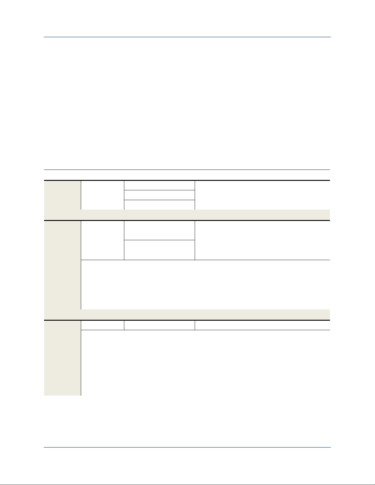
Preface
Simulator GCC Requirements
Simulator GCC Requirements
Mentor Verification IP requires that the simulator’s installation directory includes the GCC
libraries shown in Table 1. If the installation of the GCC libraries was an optional part of the
simulator’s installation and the Mentor VIP does not find these libraries, you will see an error
similar to the following error:
ModelSim / Questa Sim
# ** Error: (vsim-8388) Could not find the MVC shared library : GCC not
found in installation directory (/home/user/altera2/13.1/modelsim_ase) for
platform "linux". Please install GCC version "gcc-4.5.0-linux"
Table 1. Simulator GCC Requirements
Simulator Version GCC version(s) Search Path
Mentor Questa SIM / ModelSim
10.1d / 10.2b 4.5.0 (Linux 32-bit) <install dir>/gcc-4.5.0-linux
4.5.0 (Linux 64-bit) <install dir>/gcc-4.5.0-linux_x86_64
4.2.1 (Windows 32-bit) <install dir>/gcc-4.2.1-mingw32vc9
Synopsys VCS/VCS-MX
2013.06 4.5.2 (Linux 32-bit) $VCS_HOME/gnu/linux/4.5.2_32-shared
4.5.2 (Linux 64-bit) $VCS_HOME/gnu/linux/4.5.2_64-shared
Notes:
Although a 32-bit executable simulation is supported, VCS requires a 64-bit Linux
OS. A 32-bit Linux OS is no longer supported.
If the environment variable VG_GNU_PACKAGE is set, this variable is used
instead of the VCS_HOME environment variable.
Cadence Incisive Enterprise Simulator
12.20.014 4.4 (Linux 32/64-bit) <install dir>/tools/cdsgcc/gcc/4.4
Notes:
Although a 32-bit executable simulation is supported, IES requires a 64-bit Linux
OS. A 32-bit Linux OS is no longer supported.
Use the cds_tools.sh executable to find the Incisive installation. Ensure $PATH
includes the Installation path and <install dir>/tools/cdsgcc/gcc/4.4/install/bin. Also,
ensure the LD_LIBRARY_PATH includes <install
dir>/tools/cdsgcc/gcc/4.4/install/lib.
$VCS_HOME/gnu/4.5.2_32-shared
$VCS_HOME/gnu/4.5.2_64-shared
Mentor VIP AE AXI3/4 User Guide, V10.2b
September 2013
3
Page 22

Preface
AXI3 and AXI4 Syntax References
AXI3 and AXI4 Syntax References
Throughout this user guide, the syntax axi or axi4 is used when an AXI3 or AXI4 protocol
argument is referenced: axi is used for AXI3 protocol arguments; axi4 is used for AXI4 protocol
arguments. Uppercase AXI3 and AXI4 is used for enumerated arguments.
When a task is applicable to both AXI3 and AXI4 protocols, either a single (*) or double
asterisk (**) is used in the syntax description. A single asterisk is used for nonenumerated
arguments; a double asterisk is used for enumerated arguments.
4
Mentor VIP AE AXI3/4 User Guide, V10.2b
September 2013
Page 23

Chapter 1
Mentor VIP Altera Edition
The Mentor® Verification IP (VIP) Altera® Edition (AE) provides bus functional models
(BFMs) to simulate the behavior and to facilitate IP verification. The Mentor VIP AE includes
the following interfaces:
• AXI3
• AXI4
TM
BFM with master, slave, and inline monitor interfaces
TM
BFM with master, slave, and inline monitor interfaces
Advantages of Using BFMs and Monitors
Using the Mentor VIP AE has the following advantages:
• Accelerates the verification process by providing key verification testbench
components.
• Provides BFM components that implement the AMBA AXI Protocol Specification,
which serves as a reference for the protocol.
• Provides a full suite of configurable assertion checking in each BFM.
Implementation of BFMs
The Mentor VIP AE BFMs, master, slave, and inline monitor components are implemented in
SystemVerilog. Also included are wrapper components so that the BFMs can be used in VHDL
verification environments with simulators that support mixed-language simulation.
The Mentor VIP AE provides a set of APIs for each BFM that you can use to construct,
instantiate, control, and query signals in all BFM components. Your test programs must use
only these public access methods and events to communicate with each BFM. To ensure
support in current and future releases, your test programs must use the standard set of APIs to
interface with the BFMs. Nonstandard APIs and user-generated interfaces can not be supported
in future releases.
The test program drives the stimulus to the DUTs and determines whether the behavior of the
DUTs is correct by analyzing the responses. The BFMs translate the test program stimuli
(transactions), creating the signaling for the AMBA AXI Protocol Specification. The BFMs also
check for protocol compliance by firing an assertion when a protocol error is observed.
Mentor VIP AE AXI3/4 User Guide, V10.2b
September 2013
5
Page 24

Mentor VIP Altera Edition
Note
What Is a Transaction?
What Is a Transaction?
A transaction for Mentor VIP AE represents an instance of information that is transferred
between a master and a slave peripheral, and that adheres to the protocol used to transfer the
information. For example, a write transaction transfers an address phase, a data burst, followed
by a response phase. A subsequent instance of transferred information requires a new and
unique transaction.
Each transaction has a dynamic Transaction Record that exists for the life of the transaction.
The life of a transaction record starts when it is created and ends when the transaction
completes. The transaction record is automatically discarded when the transaction ends. When
created, a transaction contains transaction fields that you set to define two transaction aspects:
the protocol fields that are transferred over the protocol signals and operation fields that
determine how the information is transferred and when the transfer is complete. For example, a
write transaction record holds the protection information in the prot protocol field; the value of
this field is transferred over the AWPROT protocol signals during an address phase. A write
transaction also has a transaction_done operation field that indicates when the transaction is
complete; this field is not transferred over the protocol signals. These two types of transaction
fields, protocol and operation, establish a dynamic record during the life of the transaction.
In addition to transaction fields, you specify arguments to tasks, functions, and procedures that
permit you to create, set, and get the dynamic transaction record during the lifetime of a
transaction. Each BFM has an API that controls how you access the BFM transaction record.
How you access the record also depends on the source code language, whether it is VHDL or
SystemVerilog. Methods for accessing transactions based on the language you use are
explained in detail in the relevant chapters of this user guide.
An AXI Transaction
The following description of an AXI transaction is applicable to AXI3 and AXI4 protocols.
A complete read/write transaction transfers information between a master and a slave
peripheral. Transaction fields, described in the previous section, What Is a Transaction?
determine what is transferred and how information is transferred. During the lifetime of a
transaction, the roles of the master and slave ensure that a transaction completes successfully
and that transferred information adheres to the protocol specification. Information flows in both
directions during a transaction with the master initiating the transaction and the slave reporting
back to the master that the transaction has completed.
An AXI protocol uses five channels (three write channels and two read channels) to transfer
protocol information. Each of these channels has a pair of handshake signals, *VALID and
*READY, that indicates valid information on a channel and the acceptance of the information
from the channel.
6
Mentor VIP AE AXI3/4 User Guide, V10.2b
September 2013
Page 25
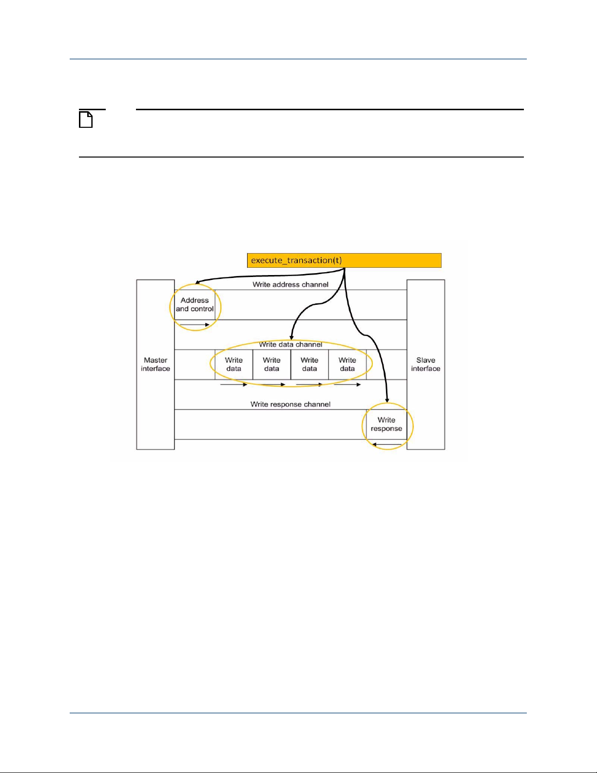
Mentor VIP Altera Edition
Note
An AXI Transaction
AXI Write Transaction Master and Slave Roles
The following description of a write transaction references SystemVerilog BFM API
tasks. There are equivalent VHDL BFM API procedures that perform the same
functionality.
For a write transaction, the master calls the create_write_transaction() task to define the
information to be transferred and then calls the execute_transaction() task to initiate the transfer
of information as Figure illustrates.
Figure 1-1. Execute Write Transaction
Mentor VIP AE AXI3/4 User Guide, V10.2b
September 2013
7
Page 26
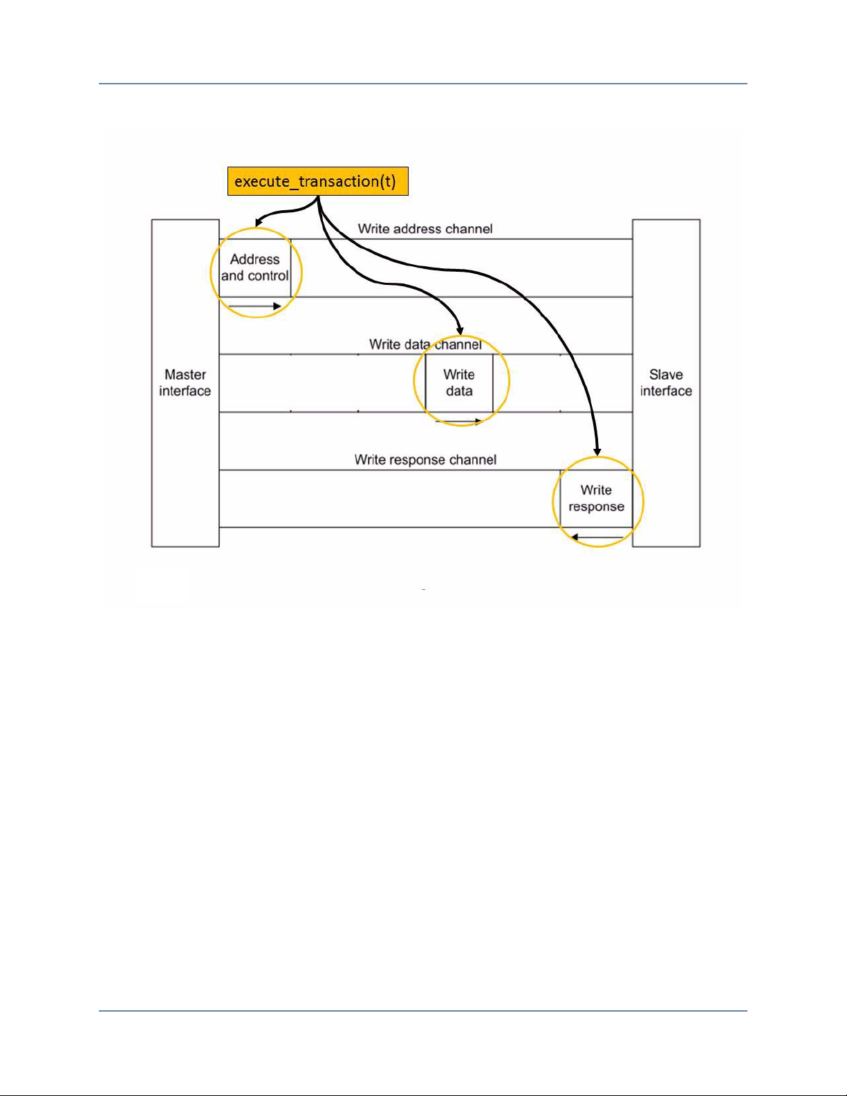
Mentor VIP Altera Edition
An AXI Transaction
The execute_transaction() task results in the master calling the execute_write_addr_phase()
task followed by the execute_write_data_burst() task . The execute_write_data_burst() calls the
execute_write_data_phase() task for each phase (beat) of the burst defined by a burst_length
transaction field as illustrated in Figure 1-2.
8
Mentor VIP AE AXI3/4 User Guide, V10.2b
September 2013
Page 27
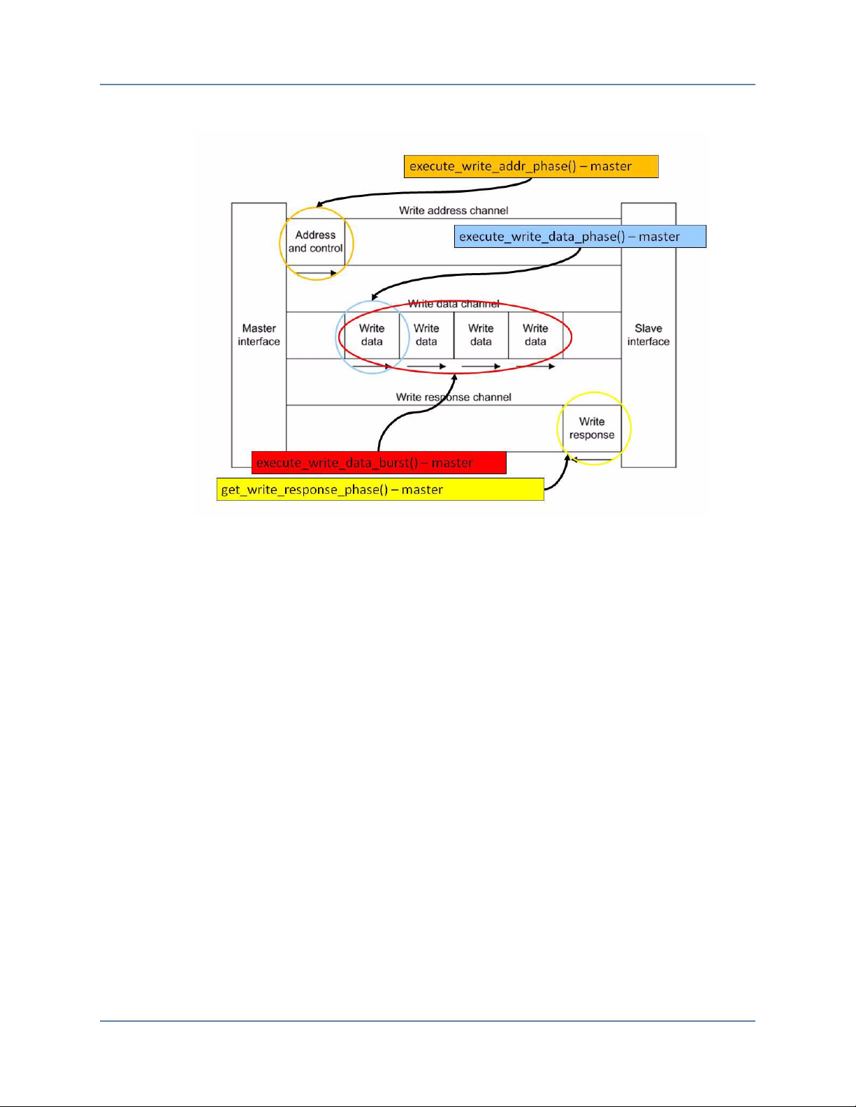
Figure 1-2. Master Write Transaction Phases
Mentor VIP Altera Edition
An AXI Transaction
The master then calls the get_write_response_phase() task to receive the response from the
slave and to complete its role in the write transaction.
The slave also creates a transaction by calling the create_slave_transaction() task to accept the
transfer of information from the master. The address phase and data burst are received by the
slave calling the get_write_addr_phase() task, followed by the get_write_data_burst() task. The
get_write_data_burst() calls the get_write_data_phase() task for each phase (beat) of the burst
defined by a burst_length transaction field, as illustrated in Figure 1-3.
Mentor VIP AE AXI3/4 User Guide, V10.2b
September 2013
9
Page 28
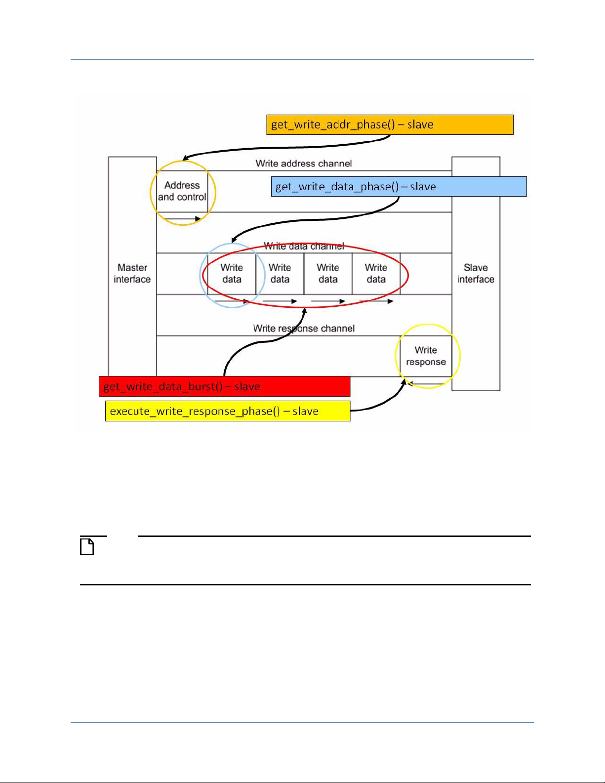
Mentor VIP Altera Edition
Note
An AXI Transaction
Figure 1-3. Slave Write Transaction Phases
The slave then executes a write response phase by calling the execute_write_response_phase()
task and completes its role in the write transaction.
AXI Read Transaction Master and Slave Roles
The following description of a read transaction references the SystemVerilog BFM API
tasks. There are equivalent VHDL BFM API procedures that perform the same
functionality.
A read transaction is similar to a write transaction. The master initiates the read by calling the
create_read_transaction() and execute_transaction() tasks. The execute_transaction() calls the
the execute_read_addr_phase() task followed by the get_read_data_burst() task. The
get_read_data_burst() calls the get_read_data_phase() task for each phase (beat) of the burst
defined by a burst_length transaction field, as illustrated in Figure 1-4.
10
Mentor VIP AE AXI3/4 User Guide, V10.2b
September 2013
Page 29
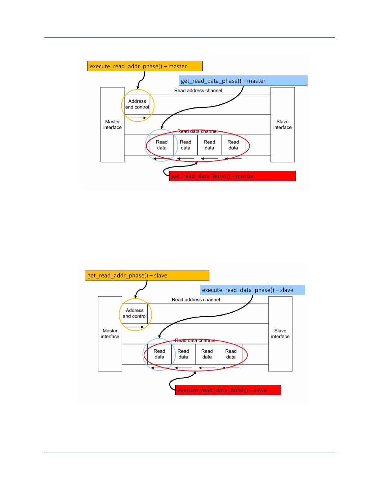
Mentor VIP Altera Edition
An AXI Transaction
Figure 1-4. Master Read Transaction Phases
The slave creates a read transaction by calling the create_slave_transaction() task to accept the
transfer of read information from the master. The slave accepts the address phase by calling the
get_read_addr_phase() task, and then executes the data burst by calling the
execute_read_data_burst() task. The execute_read_data_burst() calls the
execute_read_data_phase() task for each phase (beat) of the burst defined by the burst_length
transaction field, as illustrated in Figure 1-5.
Figure 1-5. Slave Read Transaction Phases
Mentor VIP AE AXI3/4 User Guide, V10.2b
September 2013
11
Page 30

Mentor VIP Altera Edition
An AXI Transaction
12
Mentor VIP AE AXI3/4 User Guide, V10.2b
September 2013
Page 31

Chapter 2
SV BFM API
Configuration
Creating
Transaction
Waiting Events
Executing
Transaction
Access
Transaction
create*_transaction
1
set_config/get_config
wait_on
get*_burst/get*_phase
3
Rx_Transaction
queue
queue
Tx_Transaction
Configuration
Wire Level
Notes: 1. Refer to create*_transaction()
2. Refer to execute_transaction(), execute*_burst(), execute*_phase()
3. Refer to get*()
get_rw_transaction/get*_burst/get*_phase
3
get*_addr/get*_data
3
execute_transaction, execute*_burst, execute*_phase
2
SV Interface
Test Program SV
SystemVerilog API Overview
This section provides the functional description of the SystemVerilog Application
Programming Interface (API) for all the BFM (master, slave, and monitor) components. For
each BFM, you can configure the protocol transaction fields that are executed on the protocol
signals, as well as control the operational transaction fields that permit delays to be introduced
between the handshake signals for each of the five address, data, and response channels.
In addition, each BFM API has tasks that wait for certain events to occur on the system clock
and reset signals, and tasks to get and set information about a particular transaction.
Figure 2-1. SystemVerilog BFM Internal Structure
Mentor VIP AE AXI3/4 User Guide, V10.2b
September 2013
13
Page 32

SystemVerilog API Overview
Note
Note
Configuration
Configuration
Configuration sets timeout delays, error reporting, and other attributes of the BFM. Each BFM
has a set_config() function that sets the configuration of the BFM. Refer to the individual BFM
APIs for details.
Each BFM also has a get_config() function that returns the configuration of the BFM. Refer to
the individual BFM APIs for details.
set_config()
The following test program code sets the burst timeout factor for a transaction in the master
BFM.
// Setting the burst timeoutfactor to 1000
master_bfm.set_config(AXI_CONFIG_BURST_TIMEOUT_FACTOR, 1000);
The above test program code segment is for AXI3 BFMs. Substitute the
AXI_CONFIG_BURST_TIMEOUT_FACTOR enumeration with
AXI4_CONFIG_BURST_TIMEOUT_FACTOR for AXI4 BFMs.
get_config()
The following test program code gets the protocol signal hold time in the master BFM.
// Getting hold time value
hold_time = master_bfm.get_config(AXI_CONFIG_HOLD_TIME);
The above test program code segment is for AXI3 BFMs. Substitute the
AXI_CONFIG_HOLD_TIME enumeration with AXI4_CONFIG_HOLD_TIME for AXI4
BFMs.
Creating Transactions
To transfer information between a master BFM and slave DUT over the protocol signals, a
transaction must be created in the master test program. Similarly, to transfer information
between a master DUT and a slave BFM, a transaction must be created in the slave test
program. To monitor the transfer of information using a monitor BFM, a transaction must be
created in the monitor test program.
When you create a transaction, a Transaction Record is created and exists for the life of the
transaction. This transaction record can be accessed by the BFM test programs during the life of
the transaction as it transfers information between the master and slave.
14
Mentor VIP AE AXI3/4 User Guide, V10.2b
September 2013
Page 33

SystemVerilog API Overview
Creating Transactions
Transaction Record
The transaction record contains two types of transaction fields, protocol and operational, that
either transfer information over the protocol signals or define how and when a transfer occurs.
Protocol fields contain transaction information that is transferred over protocol signals. For
example, the prot field is transferred over the AWPROT protocol signals during a write
transaction.
Operational fields define how and when the transaction is transferred. Their content is not
transferred over protocol signals. For example, the operation_mode field controls the
blocking/nonblocking operation of a transaction, but this information is not transferred over the
protocol signals.
AXI3 Transaction Definition
The transaction record exists as a SystemVerilog class definition in each BFM. Example 2-1
shows the definition of the axi_transaction class members that form the transaction record.
Example 2-1. AXI3 Transaction Definition
// Global Transaction Class
class axi_transaction;
// Protocol
bit [((`MAX_AXI_ADDRESS_WIDTH) - 1):0] addr;
axi_size_e size;
axi_burst_e burst;
axi_lock_e lock;
axi_cache_e cache;
axi_prot_e prot;
bit [((`MAX_AXI_ID_WIDTH) - 1):0] id;
bit [3:0] burst_length;
bit [((((`MAX_AXI_RDATA_WIDTH > `MAX_AXI_WDATA_WIDTH) ?
`MAX_AXI_RDATA_WIDTH : `MAX_AXI_WDATA_WIDTH)) - 1):0] data_words [];
bit [(((`MAX_AXI_WDATA_WIDTH / 8)) - 1):0] write_strobes [];
axi_response_e resp[];
bit [7:0] addr_user;
axi_rw_e read_or_write;
int address_valid_delay;
int data_valid_delay[];
int write_response_valid_delay;
int address_ready_delay;
int data_ready_delay[];
int write_response_ready_delay;
// Housekeeping
bit gen_write_strobes = 1'b1;
axi_operation_mode_e operation_mode = AXI_TRANSACTION_BLOCKING;
axi_delay_mode_e delay_mode = AXI_VALID2READY;
axi_write_data_mode_e write_data_mode = AXI_DATA_AFTER_ADDRESS;
bit data_beat_done[];
bit transaction_done;
...
endclass
Mentor VIP AE AXI3/4 User Guide, V10.2b
September 2013
15
Page 34

SystemVerilog API Overview
Note
Note
Creating Transactions
The axi_transaction class code above is shown for information only. Access to each
transaction record during its life is performed by various set*() and get*() tasks described
later in this chapter.
AXI4 Transaction Definition
The transaction record exists as a SystemVerilog class definition in each BFM. Example 2-2
shows the definition of the axi4_transaction class members that form the transaction record.
Example 2-2. AXI4 Transaction Definition
// Global Transaction Class
class axi4_transaction;
// Protocol
axi4_rw_e read_or_write;
bit [((`MAX_AXI4_ADDRESS_WIDTH) - 1):0] addr;
axi4_prot_e prot;
bit [3:0] region;
axi4_size_e size;
axi4_burst_e burst;
axi4_lock_e lock;
axi4_cache_e cache;
bit [3:0] qos;
bit [((`MAX_AXI4_ID_WIDTH) - 1):0] id;
bit [7:0] burst_length;
bit [((`MAX_AXI4_USER_WIDTH) - 1):0] addr_user;
bit [((((`MAX_AXI4_RDATA_WIDTH > `MAX_AXI4_WDATA_WIDTH) ?
`MAX_AXI4_RDATA_WIDTH : `MAX_AXI4_WDATA_WIDTH)) - 1):0] data_words [];
bit [(((`MAX_AXI4_WDATA_WIDTH / 8)) - 1):0] write_strobes [];
axi4_response_e resp[];
int address_valid_delay;
int data_valid_delay[];
int write_response_valid_delay;
int address_ready_delay;
int data_ready_delay[];
int write_response_ready_delay;
// Housekeeping
bit gen_write_strobes = 1'b1;
axi4_operation_mode_e operation_mode = AXI4_TRANSACTION_BLOCKING;
axi4_write_data_mode_e write_data_mode = AXI4_DATA_AFTER_ADDRESS;
bit data_beat_done[];
bit transaction_done;
...
endclass
The axi4_transaction class code above is shown for information only. Access to each
transaction record during its life is performed by various set*() and get*() tasks described
later in this chapter.
16
Mentor VIP AE AXI3/4 User Guide, V10.2b
September 2013
Page 35

SystemVerilog API Overview
Creating Transactions
The contents of the transaction record is defined in Table 2-1 below.
Table 2-1. Transaction Fields
Transaction Field Description
Protocol Transaction Fields
addr A bit vector (the length is equal to the ARADDR/AWADDR
signal bus width) containing the starting address of the first
transfer (beat) of a transaction. The addr value is transferred
over the ARADDR or AWADDR signals for a read or write
transaction, respectively.
prot An enumeration containing the protection type of a transaction.
region (AXI4) A 4-bit vector containing the region identifier of a
size An enumeration to hold the size of a transaction. The types of
The types of protection are:
**_NORM_SEC_DATA (default)
**_PRIV_SEC_DATA
**_NORM_NONSEC_DATA
**_PRIV_NONSEC_DATA
**_NORM_SEC_INST
**_PRIV_SEC_INST
**_NORM_NONSEC_INST
**_PRIV_NONSEC_INST
The prot value is transferred over the ARPROT or AWPROT
signals for a read or write transaction, respectively.
transaction. The region value is transferred over the
ARREGION or AWREGION signals for a read or write
transaction, respectively.
size are:
**_BYTES_1
**_BYTES_2
**_BYTES_4
**_BYTES_8
**_BYTES_16
**_BYTES_32
**_BYTES_64
**_BYTES_128
The size value is transferred over the ARSIZE or AWSIZE
signals for a read or write transaction, respectively.
burst An enumeration to hold the burst of a transaction. The types of
burst are:
**_FIXED
**_INCR
**_WRAP
**_BURST_RSVD
The burst value is transferred over the ARBURST or
AWBURST signals for a read or write transaction, respectively.
Mentor VIP AE AXI3/4 User Guide, V10.2b
September 2013
17
Page 36

SystemVerilog API Overview
Creating Transactions
Table 2-1. Transaction Fields (cont.)
Transaction Field Description
lock An enumeration to hold the lock of a transaction. The types of
cache (AXI3) An enumeration to hold the cache of a transaction. The
lock are:
**_NORMAL
**_EXCLUSIVE
(AXI3) AXI_LOCKED
(AXI3) AXI_LOCKED_RSVD
The lock value is transferred over the ARLOCK or AWLOCK
signals for a read or write transaction, respectively.
types of cache are:
AXI_NONCACHE_NONBUF; (default)
AXI_BUF_ONLY;
AXI_CACHE_NOALLOC;
AXI_CACHE_BUF_NOALLOC;
AXI_CACHE_RSVD0;
AXI_CACHE_RSVD1;
AXI_CACHE_WTHROUGH_ALLOC_R_ONLY;
AXI_CACHE_WBACK_ALLOC_R_ONLY;
AXI_CACHE_RSVD2;
AXI_CACHE_RSVD3;
AXI_CACHE_WTHROUGH_ALLOC_W_ONLY;
AXI_CACHE_WBACK_ALLOC_W_ONLY;
AXI_CACHE_RSVD4;
AXI_CACHE_RSVD5;
AXI_CACHE_WTHROUGH_ALLOC_RW;
AXI_CACHE_WBACK_ALLOC_RW;
The cache value is transferred over the ARCACHE or
AWCACHE signals for a read or write transaction, respectively.
cache (AXI4) An enumeration to hold the cache of a transaction. The
types of cache are:
AXI4_NONMODIFIABLE_NONBUF
AXI4_BUF_ONLY
AXI4_CACHE_NOALLOC
AXI4_CACHE_2
AXI4_CACHE_3
AXI4_CACHE_RSVD4
AXI4_CACHE_RSVD5
AXI4_CACHE_6
AXI4_CACHE_7
AXI4_CACHE_RSVD8
AXI4_CACHE_RSVD9
AXI4_CACHE_10
AXI4_CACHE_11
AXI4_CACHE_RSVD12
AXI4_CACHE_RSVD13
AXI4_CACHE_14
AXI4_CACHE_15
The cache value is transferred over the ARCACHE or
AWCACHE signals for a read or write transaction, respectively.
18
Mentor VIP AE AXI3/4 User Guide, V10.2b
September 2013
Page 37

Table 2-1. Transaction Fields (cont.)
Transaction Field Description
SystemVerilog API Overview
Creating Transactions
qos (AXI4) A 4-bit vector to hold the Quality of Service (qos)
id A bit vector (of length equal to the ARID/AWID signal bus width)
burst_length A 4-bit (8-bit for AXI4) vector to hold the burst length of a
addr_user A bit vector (of length equal to the ARUSER/AWUSER signal
data_words An unsized array of bit vectors (of length equal to the greater of
write_strobes An unsized array of bit vectors (of length equal to the WDATA
identifier of a transaction. The qos value is transferred over the
ARQOS or AWQOS signals for a read or write transaction,
respectively.
that holds the identification tag of a transaction. The id value is
transferred over the AWID/BID signals for a write transaction
and over the ARID/RID signals for a read transaction.
transaction. The burst_length value is transferred over the
ARLEN or AWLEN signals for a read or write transaction,
respectively.
bus width) to hold the address channel user data of a
transaction. The addr_data value is transferred over the
ARUSER or AWUSER signals for a read or write transaction,
respectively.
the RDATA/WDATA signal bus widths) to hold the data words
of the payload. A data_words array element is transferred over
the RDATA or WDATA signals per beat of the read or write data
channel, respectively.
signal bus width divided by 8) to hold the write strobes. A
write_strobes array element is transferred over the WSTRB
signals per beat of the write data channel.
resp An unsized enumeration array to hold the responses of a
transaction. The types of response are:
**_OKAY;
**_EXOKAY;
**_SLVERR;
**_DECERR;
A resp array element is transferred over the RRESP signals per
beat of the read data channel, and over the BRESP signals for
a write transaction, respectively.
Operational Transaction Fields
read_or_write An enumeration to hold the read or write control flag. The types
of read_or_write are:
**_TRANS_READ
**_TRANS_WRITE
address_valid_delay An integer to hold the delay value of the address channel
AWVALID and ARVALID signals (measured in ACLK cycles) for
a read or write transaction, respectively.
data_valid_delay An unsized array of integers to hold the delay values of the data
channel WVALID and RVALID signals (measured in ACLK
cycles) for a read or write transaction, respectively.
Mentor VIP AE AXI3/4 User Guide, V10.2b
September 2013
19
Page 38

SystemVerilog API Overview
Creating Transactions
Table 2-1. Transaction Fields (cont.)
Transaction Field Description
write_response_valid_delay An integer to hold the delay value of the write response channel
address_ready_delay An integer to hold the delay value of the address channel
data_ready_delay An unsized array of integers to hold the delay values of the data
write_response_ready_delay An integer to hold the delay value of the write response channel
gen_write_strobes Automatically correct write strobes flag. Refer to Automatic
operation_mode An enumeration to hold the operation mode of the transaction.
delay_mode (AXI3) An enumeration to hold the delay mode control flag. The
BVALID signal (measured in ACLK cycles) for a write
transaction.
AWREADY and ARREADY signals (measured in ACLK cycles)
for a read or write transaction, respectively.
channel WREADY and RREADY signals (measured in ACLK
cycles) for a read or write transaction, respectively.
BREADY signal (measured in ACLK cycles) for a write
transaction.
Generation of Byte Lane Strobes for details.
The two types of operation_mode are:
**_TRANSACTION_NON_BLOCKING
**_TRANSACTION_BLOCKING
types of delay_mode are:
AXI_VALID2READY
AXI_TRANS2READY
Refer to AXI3 BFM Delay Mode for details.
write_data_mode An enumeration to hold the write data mode control flag. The
types of write_data_mode are:
**_DATA_AFTER_ADDRESS
**_DATA_WITH_ADDRESS
data_beat_done An unsized bit array to hold the done flag for each beat in a
read or write data burst when it has completed.
transaction_done A bit to hold the done flag for a transaction when it has
completed.
The master BFM API allows you to create a master transaction by providing only the address
and burst length arguments for a read or write transaction. All other protocol transaction fields
automatically default to legal protocol values to create a complete master transaction record.
Refer to the create_read_transaction() and create_write_transaction() functions for default
protocol read and write transaction field values.
The slave BFM API allows you to create a slave transaction without providing any arguments.
All protocol transaction fields automatically default to legal protocol values to create a complete
slave transaction record. Refer to the create_slave_transaction() function for default protocol
transaction field values.
20
Mentor VIP AE AXI3/4 User Guide, V10.2b
September 2013
Page 39

SystemVerilog API Overview
Note
Note
Executing Transactions
The monitor BFM API allows you to create a monitor transaction without providing any
arguments. All protocol transaction fields automatically default to legal protocol values to
create a complete slave transaction record. Refer to the create_monitor_transaction() function
for default protocol transaction field values.
If you change the default value of a protocol transaction field, this value is valid for all
future transactions until a new value is set.
create*_transaction()
There are two master BFM API functions available to create transactions,
create_read_transaction() and create_write_transaction(), a create_slave_transaction() for the
slave BFM API, and a create_monitor_transaction() for the monitor BFM API.
For example, the following master BFM test program creates a simple write transaction with a
start address of 1, and a single data phase with a data value of 2, the master BFM test program
would contain the following code:
// Define a variable trans of type axi_transaction
axi_transaction write_trans;
// Create master write transaction
write_trans = bfm.create_write_transaction(1);
write_trans.data_words[0] = 2;
For example, to create a simple slave transaction the slave BFM test program would contain the
following code:
// Define a variable slave_trans of type axi_transaction
axi_transaction slave_trans;
// Create slave transaction
slave_trans = bfm.create_slave_transaction();
The above test program code segments are for AXI3 BFMs. Substitute the
axi_transaction type definition with axi4_transaction for AXI4 BFMs.
Executing Transactions
Executing a transaction in a master/slave BFM test program initiates the transaction onto the
protocol signals. Each master/slave BFM API has execution tasks that push transactions into the
BFM internal transaction queues. Figure 2-1 on page 13 illustrates the internal BFM structure.
Mentor VIP AE AXI3/4 User Guide, V10.2b
September 2013
21
Page 40

SystemVerilog API Overview
Executing Transactions
execute_transaction(), execute*_burst(), execute*_phase()
If the DUT is a slave, then the execute_transaction() task is called in the master BFM test
program. If the DUT is a master, then the execute*_burst() and execute*_phase() tasks are
called in the slave BFM test program.
For example, to execute a master write transaction the master BFM test program contains the
following code:
22
Mentor VIP AE AXI3/4 User Guide, V10.2b
September 2013
Page 41

SystemVerilog API Overview
Note
Waiting Events
// By default the execution of a transaction will block
bfm.execute_transaction(write_trans);
For example, to execute a slave write response phase, the slave BFM test program contains the
following code:
// By default the execution of a transaction will block
bfm.execute_write_response_phase(slave_trans);
Waiting Events
Each BFM API has tasks that block the test program code execution until an event has occurred.
The wait_on() task blocks the test program until an ACLK or ARESETn signal event has
occurred before proceeding.
The get*_transaction(), get*_burst(), get*_phase(), get*_cycle() tasks block the test program
code execution until a complete transaction, burst, phase or cycle has occurred, respectively.
wait_on()
For example, a BFM test program can wait for the positive edge of the ARESETn signal using
the following code:
// Block test program execution until the positive edge of the clock
bfm.wait_on(AXI_RESET_POSEDGE);
The above test program code segments are for AXI3 BFMs. Substitute the
AXI_RESET_POSEDGE enumeration with AXI4_RESET_POSEDGE for AXI4 BFMs.
get*_transaction(), get*_burst(), get*_phase(), get*_cycle()
For example, a slave BFM test program can use a received write address phase to form the
response of the write transaction. The test program gets the write address phase for the
transaction by calling the get_write_addr_phase() task. This task blocks until it has received the
address phase, allowing the test program to call the execute_write_response_phase() task for
the transaction at a later stage, as shown in the slave BFM test program in Example 2-3.
Example 2-3. Slave Test Program Using get_write_addr_phase()
slave_trans = bfm.create_slave_transaction();
bfm.get_write_addr_phase(slave_trans);
...
bfm.execute_write_response_phase(slave_trans);
Mentor VIP AE AXI3/4 User Guide, V10.2b
September 2013
23
Page 42

SystemVerilog API Overview
Note
Note
Access Transaction Record
Not all BFM APIs support the full complement of get*_transaction(), get*_burst(),
get*_phase(), get*_cycle() tasks. Refer to the individual master, slave or monitor BFM
API for details.
Access Transaction Record
Each BFM API has tasks that can access a complete or partially complete Transaction Record.
The set*() and get*() tasks are used in a test program to set and get information from the
transaction record.
The set*() and get*() tasks are not explicitly described in each BFM API chapter. The
simple rule for the task name is set_ or get_ followed by the name of the transaction field
accessed. Refer to “Transaction Fields” on page 17 for transaction field name details.
set*()
For example, to set the WSTRB write strobes signal for the first phase (beat) in the Transaction
Record of a write transaction, the master test program would use the set_write_strobes() task, as
shown in the code below.
write_trans.set_write_strobes(4'b0010, 0);
get*()
For example, a slave BFM test program uses a received write address phase to get the AWPROT
signal value from the Transaction Record, as shown in the slave BFM test program code below.
// Define a variable prot_value of type axi_transaction
axi_prot_e prot_value;
slave_trans = bfm.create_slave_transaction();
// Wait for a write address phase
bfm.get_write_addr_phase(slave_trans);
... …
// Get the AWPROT signal value of the slave transaction
prot_value = bfm.get_prot(slave_trans);
24
Mentor VIP AE AXI3/4 User Guide, V10.2b
September 2013
Page 43

SystemVerilog API Overview
Note
Operational Transaction Fields
The above test program code segments are for AXI3 BFMs. For AXI4 BFMs, substitute
the axi_transaction type definition with axi4_transaction and axi_prot_e with
axi4_prot_e.
Operational Transaction Fields
Operational transaction fields control the way a transaction is executed onto the protocol
signals. They also indicate when a data phase (beat) or transaction is complete.
Automatic Generation of Byte Lane Strobes
The master BFM permits unaligned and narrow write transfers by using byte lane strobe
(WSTRB) signals to indicate which byte lanes contain valid data per data phase (beat).
When you create a write transaction in your master BFM test program, the write_strobes
variable is available to store the write strobe values for each write data phase (beat) in the
transaction. To assist you in creating the correct byte lane strobes, automatic correction of any
previously set write_strobes is performed by default during execution of the write transaction,
or write data phase (beat). You can disable this default behavior by setting the operational
transaction field gen_write_strobes = 0, which allows any previously set write_strobes to pass
through uncorrected onto the protocol WSTRB signals. In this mode, with the automatic
correction disabled, you are responsible for setting the correct write_strobes for the whole
transaction.
The automatic correction algorithm performs a bit-wise AND operation on any previously set
write_strobes. To do the corrections, the correction algorithm uses the equations described in
the AMBA AXI Protocol Specification, section A3.4.1 that define valid write data byte lanes
for legal protocol. Therefore, if you require automatic generation of all write_strobes, before the
write transaction executes, you must set all write_strobes to 1, indicating that all bytes lanes
initially contain valid write data prior to the execution of the write transaction. Automatic
correction then sets the relevant write_strobes to 0 to produce legal protocol WSTRB signals.
For example, Figure 2-2 below shows byte lanes that can contain valid data for a write
transaction with a starting address = 0x01, size = 0b001 (2 bytes), type = INCR, and the length
= 0b0010 (3 beats) for a 32-bit write data bus.
Mentor VIP AE AXI3/4 User Guide, V10.2b
September 2013
25
Page 44

SystemVerilog API Overview
Note
Operational Transaction Fields
Figure 2-2. Valid Data on Byte Lanes During a Write Transaction
In the above example, if you set all write_strobes[] array elements to 1 before executing the
write transaction, automatic correction produces the following results while the transaction
executes.
Prior to Execution During Execution
1st data phase write_strobes[0]=0b1111 -> write_strobes[0]=0b0010
2nd data phase write_strobes[1]=0b1111 -> write_strobes[1]=0b1100
3rd data phase write_strobes[2]=0b1111 -> write_strobes[2]=0b0011
If you randomly set all write_strobes[] array elements to 0 or 1, before executing the write
transaction, automatic correction corrects only those write_strobes[] array elements that were
previously set to 1, as shown below.
Prior to Execution During Execution
1st data phase write_strobes[0]=0b1010 -> write_strobes[0]=0b0010
2nd data phase write_strobes[1]=0b1010 -> write_strobes[1]=0b1000
3rd data phase write_strobes[2]=0b1010 -> write_strobes[2]=0b0010
To automatically generate all WSTRB signals for a write transaction, set all
write_strobes[] array elements to 1 before executing the write transaction or write data
burst.
Operation Mode
By default, each read or write transaction performs a blocking operation which prevents a
following transaction from starting until the current active transaction completes.
You can configure this behavior to be nonblocking by setting the operation_mode transaction
field to the enumerate type value AXI_TRANSACTION_NON_BLOCKING instead of the
default AXI_TRANSACTION_BLOCKING.
26
Mentor VIP AE AXI3/4 User Guide, V10.2b
September 2013
Page 45

SystemVerilog API Overview
Note
Operational Transaction Fields
For example, in a master BFM test program you create a transaction by calling the
create_read_transaction() or create_write_transaction() tasks which creates a transaction
record. Before executing the transaction record, the operation_mode can be changed as follows:
// Create a write transaction to create a transaction record
trans = bfm.create_write_transaction(1);
// Change operation_mode to be nonblocking in the transaction record
trans.operation_mode(AXI_TRANSACTION_NON_BLOCKING);
The above test program code segments are for AXI3 BFMs. Substitute the
AXI_TRANSACTION_NON_BLOCKING enumeration with
AXI4_TRANSACTION_NON_BLOCKING for AXI4 BFMs.
Channel Handshake Delay
Each of the five protocol channels have *VALID and *READY handshake signals that control
the rate at which information is transferred between a master and slave. The API to control these
handshake signals differs between the AXI3 BFMs and AXI4 BFMs. Refer to the AXI3 BFM
Handshake Delay and AXI3 BFM Delay Mode for details of the AXI3 BFM API, and AXI4
BFM Handshake Delay for details of the AXI4 BFM API.
AXI3 BFM Handshake Delay
The delay between the *VALID and *READY handshake signals for each of the five protocol
channels can be configured. The delay can be defined per phase (beat) basis for a particular
transaction, measured from the positive edge of ACLK when *VALID is asserted. The delay can
also be set from the completion of a previous transaction phase (*VALID and *READY both
asserted).
AXI3 BFM Handshake Signal Delay Transaction Fields
The transaction record contains transaction fields to configure the desired handshake delay
pattern for a particular transaction phase on any of the five protocol channels. The master BFM
configures the *VALID and *READY signal delays that it asserts, and the slave BFM configures
the *VALID and *READY signal delays that it asserts. Table 2-2 specifies which operational
delay transaction fields are configured by the master and slave BFMs.
Mentor VIP AE AXI3/4 User Guide, V10.2b
September 2013
27
Page 46

SystemVerilog API Overview
Note
Operational Transaction Fields
Table 2-2. Handshake Signal Delay Transaction Fields
Signal Operational Transaction Field Configuration BFM
AWVALID address_valid_delay Master
AWREADY address_ready_delay Slave
WVALID data_valid_delay Master
WREADY data_ready_delay Slave
BVALID write_response_valid_delay Slave
BREADY write_response_ready_delay Master
ARVALID address_valid_delay Master
ARREADY address_ready_delay Slave
RVALID data_valid_delay Slave
RREADY data_ready_delay Master
The data channel handshake signal transaction fields (data_valid_delay[] and
data_ready_delay[]) are defined as arrays so that the *VALID to *READY delay can be
configured on a per data phase (beat) basis in a transaction.
AXI4 BFM Handshake Delay
The delay between the *VALID and *READY handshake signals for each of the five protocol
channels is controlled in a BFM test program using execute_*_ready(), get_*_ready(), and
get_*_cycle() tasks. The execute_*_ready() tasks place a value onto the *READY signals and
the get_*_ready() tasks retrieve a value from the *READY signals. The get_*_cycle() tasks wait
for a *VALID signal to be asserted and are used to insert a delay between the *VALID and
*READY signals in the BFM test program.
For example, the master BFM test program code below inserts a specified delay between the
read channel RVALID and RREADY handshake signals using the execute_read_data_ready()
and get_read_data_cycle() tasks.
// Set the RREADY signal to ‘0’ so that it is nonblocking
fork
bfm.execute_read_data_ready(1'b0);
join_none
// Wait until the RVALID signal is asserted and then wait_on the specified
// number of ACLK cycles
bfm.get_read_data_cycle;
repeat(5) bfm.wait_on(AXI4_CLOCK_POSEDGE);
// Set the RREADY signal to ‘1’ so that it blocks for an ACLK cycle
bfm.execute_read_data_ready(1'b1);
28
Mentor VIP AE AXI3/4 User Guide, V10.2b
September 2013
Page 47

SystemVerilog API Overview
Note
Note
Operational Transaction Fields
AXI4 BFM *VALID Signal Delay Transaction Fields
The transaction record contains a *_valid_delay transaction field for each of the five protocol
channels to configure the delay value prior to the assertion of the *VALID signal for the
channel. The master BFM holds the delay configuration for the *VALID signals that it asserts,
and the slave BFM holds the delay configuration for the *VALID signals that it asserts.
Table 2-3 below specifies which *_valid_delay fields are configured by the master and slave
BFMs.
Table 2-3. Master and Slave*_valid_delay Configuration Fields
Signal Operational Transaction Field Configuration BFM
AWVALID address_valid_delay Master
WVALID data_valid_delay Master
BVALID write_response_valid_delay Slave
ARVALID address_valid_delay Master
RVALID data_valid_delay Slave
In the transaction record, the data channel handshake signal transaction field
(data_valid_delay[]) is defined as an array, which allows you to configure the *VALID
delay on a per data phase (beat) basis in a transaction.
AXI4 BFM *READY Handshake Signal Delay Transaction Fields
The transaction record contains a *_ready_delay transaction field for each of the five protocol
channels to store the delay value that occurred between the assertion of the *VALID and
*READY handshake signals for the channel. Table 2-4 specifies the *_ready_delay field
corresponding to the *READY signal delay.
Table 2-4. Master &Slave *_ready_delay Transaction Fields
Signal Operational Transaction Field
AWREADY address_ready_delay
WREADY data_ready_delay
BREADY write_response_ready_delay
ARREADY address_ready_delay
RREADY data_ready_delay
In the transaction record, the data channel handshake signal transaction field
(data_ready_delay[]) is defined as an array so that the *READY delay can be recorded on
a per data phase (beat) basis in a transaction.
Mentor VIP AE AXI3/4 User Guide, V10.2b
September 2013
29
Page 48

SystemVerilog API Overview
*VALID
*READY
ACLK
*_valid_delay = 4
*_ready_delay = 2
Operational Transaction Fields
AXI3 BFM Delay Mode
The delay mode can be configured on a per transaction basis using the delay_mode operational
transaction field. This transaction field can be configured to the enumerated type values of
AXI_VALID2READY (default) or AXI_TRANS2READY.
The default configuration (delay_mode = AXI_VALID2READY) corresponds to the delay
measured from the positive edge of ACLK when *VALID is asserted in a transaction. Figure 2-3
demonstrates how to achieve a *VALID asserted before *READY handshake.
Figure 2-3. Operational Transaction Field delay_mode = AXI_VALID2READY
The other configuration (delay_mode = AXI_TRANS2READY) corresponds to the delay
measured from the completion of a previous transaction phase (*VALID and *READY both
asserted). Figure 2-4 demonstrates how to achieve a *READY before *VALID handshake.
30
Mentor VIP AE AXI3/4 User Guide, V10.2b
September 2013
Page 49

SystemVerilog API Overview
*VALID
*READY
ACLK
*_valid_delay = 4
*_ready_delay = 2
Operational Transaction Fields
Figure 2-4. Operational Transaction Field delay_mode = AXI_TRANS2READY
Data Beat Done
There is a data_beat_done transaction field for each transaction, defined as an array, to indicate
when each data phase (beat) has completed. Each element of the data_beat_done array is set to
1 when each data phase (beat) has completed in a data burst.
You call the get_read_data_phase() task in the master BFM test program to investigate how
many beats of a read data burst have completed by analyzing how many elements of the
data_beat_done array have been set to 1. Similarly, the get_write_data_phase() task can be
called in the slave BFM test program to analyze a write data burst.
Transaction Done
The transaction_done field in each transaction indicates when the transaction is complete.
In a master BFM test program, you call the get_read_data_burst() task to investigate whether a
read transaction is complete, and the get_write_response_phase() to investigate whether a write
transaction is complete.
Mentor VIP AE AXI3/4 User Guide, V10.2b
September 2013
31
Page 50

SystemVerilog API Overview
Operational Transaction Fields
32
Mentor VIP AE AXI3/4 User Guide, V10.2b
September 2013
Page 51

Chapter 3
Note
SystemVerilog AXI3 and AXI4 Master BFMs
This section provides information about the SystemVerilog AXI3 and AXI4 master BFMs.
Each BFM has an API that contains tasks and functions to configure the BFM and to access the
dynamic Transaction Record during the lifetime of the transaction.
Due to AXI3 protocol specification changes, for some BFM tasks, you reference the
AXI3 BFM by specifying AXI instead of AXI3.
Master BFM Protocol Support
The AXI3 master BFM supports the AMBA AXI3 protocol with restrictions described in
“Protocol Restrictions” on page 1. In addition to the standard protocol, it supports user sideband
signals AWUSER and ARUSER.
The AXI4 master BFM supports the AMBA AXI4 protocol with restrictions described in
“Protocol Restrictions” on page 1.
Master Timing and Events
For detailed timing diagrams of the protocol bus activity, refer to the relevant AMBA AXI
protocol specification chapter, which you can use to reference details of the following master
BFM API timing and events.
The AMBA AXI protocol specification does not define any timescale or clock period with
signal events sampled and driven at rising ACLK edges. Therefore, the master BFM does not
contain any timescale, timeunit, or timeprecision declarations with the signal setup and hold
times specified in units of simulator time-steps.
The simulator time-step resolves to the smallest of all the time-precision declarations in the
testbench and design IP as a result of these directives, declarations, options, or initialization
files:
• ` timescale directives in design elements.
• timeprecision declarations in design elements.
• compiler command-line options.
• simulation command-line options.
Mentor VIP AE AXI3/4 User Guide, V10.2b
September 2013
33
Page 52

SystemVerilog AXI3 and AXI4 Master BFMs
Note
Master BFM Configuration
• local or site-wide simulator initialization files.
If there is no timescale directive, the default time unit and time precision are tool specific. The
recommended practice is to use timeunit and timeprecision declarations. Refer to the
SystemVerilog LRM section 3.14 for details.
Master BFM Configuration
A master BFM supports the full range of signals defined for the AMBA AXI protocol
specification. It has parameters that configure the widths of the address, ID and data signals, and
transaction fields to specify timeout factors, slave exclusive support, setup and hold times, etc.
The address, ID and data signal widths can be changed from their default settings by assigning
them new values, usually in the top-level module of the testbench. These new values are then
passed to the master BFM using a parameter port list of the master BFM module. For example,
the code extract below shows the AXI3 master BFM with the address, ID and data signal widths
defined in module top() and passed to the master BFM mgc_axi_master parameter port list:
module top ();
parameter AXI_ADDRESS_WIDTH = 24;
parameter AXI_RDATA_WIDTH = 16;
parameter AXI_WDATA_WIDTH = 16;
parameter AXI_ID_WIDTH = 4;
mgc_axi_master #(AXI_ADDRESS_WIDTH, AXI_RDATA_WIDTH, AXI_WDATA_WIDTH,
AXI_ID_WIDTH) bfm_master(....);
In the above code extract, the mgc_axi_master is the AXI3 master BFM interface.
The following table lists parameter names for the address, ID and data signals, and their default
values.
Table 3-1. Master BFM Signal Width Parameters
Signal Width Parameter
(Note: ** = AXI or AXI4)
**_ADDRESS_WIDTH Address signal width in bits. This applies to the ARADDR and
**_RDATA_WIDTH Read data signal width in bits. This applies to the RDATA
Description
AWADDR signals. Refer to the AMBA AXI Protocol
specification for more details. Default: 32.
signals. Refer to the AMBA AXI Protocol specification for more
details. Default: 64.
**_WDATA_WIDTH Write data signal width in bits. This applies to the WDATA
34
signals. Refer to the AMBA AXI Protocol specification for more
details. Default: 64.
Mentor VIP AE AXI3/4 User Guide, V10.2b
September 2013
Page 53

SystemVerilog AXI3 and AXI4 Master BFMs
Master BFM Configuration
Table 3-1. Master BFM Signal Width Parameters
**_ID_WIDTH ID signal width in bits. This applies to the RID and WID signals.
Refer to the AMBA AXI Protocol specification for more details.
Default: 4.
AXI4_USER_WIDTH (AXI4) User data signal width in bits. This applies to the
AXI4_REGION_MAP_SIZE (AXI4) Region signal width in bits. This applies to the
ARUSER, AWUSER, RUSER, WUSER and BUSER signals.
Refer to the AMBA AXI Protocol specification for more details.
Default: 8.
ARREGION and AWREGION signals. Refer to the AMBA AXI
Protocol specification for more details. Default: 16.
Mentor VIP AE AXI3/4 User Guide, V10.2b
September 2013
35
Page 54

SystemVerilog AXI3 and AXI4 Master BFMs
Master BFM Configuration
A master BFM has configuration fields that you can set with the set_config() function to
configure timeout factors, slave exclusive support, and setup and hold times, etc. You can also
get the value of a configuration field using the get_config() function. The full list of
configuration fields is described in Table 3-2 below.
Table 3-2. Master BFM Configuration
Configuration Field (Note: ** = AXI or AXI4) Description
Timing Variables
**_CONFIG_SETUP_TIME The setup-time prior to the active edge
**_CONFIG_HOLD_TIME The hold-time after the active edge of
**_CONFIG_MAX_TRANSACTION_TIME_FACTOR The maximum timeout duration for a
**_CONFIG_BURST_TIMEOUT_FACTOR The maximum delay between the
**_CONFIG_MAX_LATENCY_AWVALID_
ASSERTION_TO_AWREADY
**_CONFIG_MAX_LATENCY_ARVALID_
ASSERTION_TO_ARREADY
**_CONFIG_MAX_LATENCY_RVALID_
ASSERTION_TO_RREADY
of ACLK, in units of simulator timesteps for all signals.
ACLK, in units of simulator time-steps
for all signals.
read/write transaction in clock cycles.
Default: 100000.
individual phases of a read/write
transaction in clock cycles. Default:
10000.
The maximum timeout duration from
the assertion of AWVALID to the
assertion of AWREADY in clock
periods. Default: 1000.
The maximum timeout duration from
the assertion of ARVALID to the
assertion of ARREADY in clock
periods. Default: 10000.
The maximum timeout duration from
the assertion of RVALID to the
assertion of RREADY in clock periods.
Default: 10000.
1
Default: 0.
1
Default: 0.
**_CONFIG_MAX_LATENCY_BVALID_
ASSERTION_TO_BREADY
**_CONFIG_MAX_LATENCY_WVALID_
ASSERTION_TO_WREADY
36
The maximum timeout duration from
the assertion of BVALID to the
assertion of BREADY in clock periods.
Default: 10000.
The maximum timeout duration from
the assertion of WVALID to the
assertion of WREADY in clock periods.
Default 10000.
Mentor VIP AE AXI3/4 User Guide, V10.2b
September 2013
Page 55

SystemVerilog AXI3 and AXI4 Master BFMs
Note
Master Assertions
Table 3-2. Master BFM Configuration (cont.)
Slave Attributes
**_CONFIG_SUPPORT_EXCLUSIVE_ACCESS Configures the support for an exclusive
slave. If enabled the BFM will expect
an EXOKAY response to a successful
exclusive transaction. If disabled the
BFM will expect an OKAY response to
an exclusive transaction. Refer to the
AMBA AXI protocol specification for
more details.
0 = disabled
1 = enabled (default)
AXI_CONFIG_SLAVE_DEFAULT_UNDER_RESET (AXI3) The slave BFM drives the
BVALID and RVALID signals low
during reset. Refer to the AMBA AXI
Protocol specification for more details.
0 = false (default)
1 = true
**_CONFIG_SLAVE_START_ADDR Configures the start address map for
**_CONFIG_SLAVE_END_ADDR Configures the end address map for
**_CONFIG_READ_DATA_REORDERING_DEPTH The slave read reordering depth. Refer
the slave.
the slave.
to the AMBA AXI Protocol specification
for more details. Default: 1.
Error Detection
**_CONFIG_ENABLE_ALL_ASSERTIONS Global enable/disable of all assertion
**_CONFIG_ENABLE_ASSERTION Individual enable/disable of assertion
1.
Refer to Master Timing and Events for details of simulator time-steps.
checks in the BFM.
0 = disabled
1 = enabled (default)
check in the BFM.
0 = disabled
1 = enabled (default)
Master Assertions
Each master BFM performs protocol error checking using the built-in assertions.
The built-in BFM assertions are independent of programming language and simulator.
AXI3 Assertion Configuration
By default, all built-in assertions are enabled in the master BFM. To globally disable them in the
master BFM, use the set_config() command as the following example illustrates:
Mentor VIP AE AXI3/4 User Guide, V10.2b
September 2013
37
Page 56

SystemVerilog AXI3 and AXI4 Master BFMs
Note
Master Assertions
set_config(AXI_CONFIG_ENABLE_ALL_ASSERTIONS,0)
Alternatively, individual built-in assertions can be disabled by using a sequence of get_config()
and set_config() commands on the respective assertion. For example, to disable assertion
checking for the AWLOCK signal changing between the AWVALID and AWREADY handshake
signals, use the following sequence of commands:
// Define a local bit vector to hold the value of the assertion bit vector
bit [255:0] config_assert_bitvector;
// Get the current value of the assertion bit vector
config_assert_bitvector = bfm.get_config(AXI_CONFIG_ENABLE_ASSERTION);
// Assign the AXI_LOCK_CHANGED_BEFORE_AWREADY assertion bit to 0
config_assert_bitvector[AXI_LOCK_CHANGED_BEFORE_AWREADY] = 0;
// Set the new value of the assertion bit vector
bfm.set_config(AXI_CONFIG_ENABLE_ASSERTION, config_assert_bitvector);
Do not confuse the AXI_CONFIG_ENABLE_ASSERTION bit vector with the
AXI_CONFIG_ENABLE_ALL_ASSERTIONS global enable/disable.
To re-enable the AXI_LOCK_CHANGED_BEFORE_AWREADY assertion, follow the above
code sequence and assign the assertion in the AXI_CONFIG_ENABLE_ASSERTION bit vector
to 1.
For a complete listing of AXI3 assertions, refer to “AXI3 Assertions” on page 665.
38
Mentor VIP AE AXI3/4 User Guide, V10.2b
September 2013
Page 57

SystemVerilog AXI3 and AXI4 Master BFMs
Note
Note
SystemVerilog Master API
AXI4 Assertion Configuration
By default, all built-in assertions are enabled in the master AXI4 BFM. To globally disable
them in the master BFM, use the set_config() command as the following example illustrates:
set_config(AXI4_CONFIG_ENABLE_ALL_ASSERTIONS,0)
Alternatively, individual built-in assertions can be disabled by using a sequence of get_config()
and set_config() commands on the respective assertion. For example, to disable assertion
checking for the AWLOCK signal changing between the AWVALID and AWREADY handshake
signals, use the following sequence of commands:
// Define a local bit vector to hold the value of the assertion bit vector
bit [255:0] config_assert_bitvector;
// Get the current value of the assertion bit vector
config_assert_bitvector = bfm.get_config(AXI4_CONFIG_ENABLE_ASSERTION);
// Assign the AXI4_LOCK_CHANGED_BEFORE_AWREADY assertion bit to 0
config_assert_bitvector[AXI4_LOCK_CHANGED_BEFORE_AWREADY] = 0;
// Set the new value of the assertion bit vector
bfm.set_config(AXI4_CONFIG_ENABLE_ASSERTION, config_assert_bitvector);
Do not confuse the AXI4_CONFIG_ENABLE_ASSERTION bit vector with the
AXI4_CONFIG_ENABLE_ALL_ASSERTIONS global enable/disable.
To re-enable the AXI4_LOCK_CHANGED_BEFORE_AWREADY assertion, follow the above
code sequence and assign the assertion in the AXI4_CONFIG_ENABLE_ASSERTION bit vector
to 1.
For a complete listing of AXI4 assertions, refer to “AXI4 Assertions” on page 678.
SystemVerilog Master API
This section describes the SystemVerilog master API.
Mentor VIP AE AXI3/4 User Guide, V10.2b
September 2013
39
Page 58

SystemVerilog AXI3 and AXI4 Master BFMs
set_config()
set_config()
This function sets the configuration of the master BFM.
Prototype
Arguments
// * = axi | axi4
function void set_config
(
input *_config_e config_name,
input *_max_bits_t config_val
);
config_name (AXI3) Configuration name:
AXI_CONFIG_SETUP_TIME
AXI_CONFIG_HOLD_TIME
AXI_CONFIG_MAX_TRANSACTION_TIME_FACTOR
AXI_CONFIG_TIMEOUT_MAX_DATA_TRANSFER
AXI_CONFIG_BURST_TIMEOUT_FACTOR
AXI_CONFIG_WRITE_CTRL_TO_DATA_MINTIME
AXI_CONFIG_MASTER_WRITE_DELAY
AXI_CONFIG_MASTER_DEFAULT_UNDER_RESET
AXI_CONFIG_SLAVE_DEFAULT_UNDER_RESET
AXI_CONFIG_ENABLE_ALL_ASSERTIONS
AXI_CONFIG_ENABLE_ASSERTION
AXI_CONFIG_MAX_LATENCY_AWVALID_ASSERTION_
TO_AWREADY
AXI_CONFIG_MAX_LATENCY_ARVALID_ASSERTION_
TO_ARREADY
AXI_CONFIG_MAX_LATENCY_RVALID_ASSERTION_
TO_RREADY
AXI_CONFIG_MAX_LATENCY_BVALID_ASSERTION_
TO_BREADY
AXI_CONFIG_MAX_LATENCY_WVALID_ASSERTION_
TO_WREADY
AXI_CONFIG_READ_DATA_REORDERING_DEPTH
AXI_CONFIG_SLAVE_START_ADDR
AXI_CONFIG_SLAVE_END_ADDR
AXI_CONFIG_MASTER_ERROR_POSITION
AXI_CONFIG_SUPPORT_EXCLUSIVE_ACCESS
(AXI4) Configuration name:
AXI4_CONFIG_SETUP_TIME
AXI4_CONFIG_HOLD_TIME
AXI4_CONFIG_BURST_TIMEOUT_FACTOR
AXI4_CONFIG_MAX_TRANSACTION_TIME_FACTOR
AXI4_CONFIG_ENABLE_RLAST
AXI4_CONFIG_ENABLE_SLAVE_EXCLUSIVE
AXI4_CONFIG_ENABLE_ALL_ASSERTIONS
AXI4_CONFIG_ENABLE_ASSERTION
AXI4_CONFIG_MAX_LATENCY_AWVALID_ASSERTION_
TO_AWREADY
AXI4_CONFIG_MAX_LATENCY_ARVALID_ASSERTION_
TO_ARREADY
AXI4_CONFIG_MAX_LATENCY_RVALID_ASSERTION_
TO_RREADY
AXI4_CONFIG_MAX_LATENCY_BVALID_ASSERTION_
TO_BREADY
AXI4_CONFIG_MAX_LATENCY_WVALID_ASSERTION_
TO_WREADY
AXI4_CONFIG_ENABLE_QOS
AXI4_CONFIG_READ_DATA_REORDERING_DEPTH
AXI4_CONFIG_SLAVE_START_ADDR
AXI4_CONFIG_SLAVE_END_ADDR
40
Mentor VIP AE AXI3/4 User Guide, V10.2b
September 2013
Page 59

SystemVerilog AXI3 and AXI4 Master BFMs
set_config()
See “Master BFM Configuration”
values.
Returns
None
AXI3 Example
set_config(AXI_CONFIG_SUPPORT_EXCLUSIVE_ACCESS, 1);
set_config(AXI_CONFIG_BURST_TIMEOUT_FACTOR, 1000);
AXI4 Example
set_config(AXI4_CONFIG_ENABLE_SLAVE_EXCLUSIVE, 1);
set_config(AXI4_CONFIG_BURST_TIMEOUT_FACTOR, 1000);
on page 34 for descriptions and valid
Mentor VIP AE AXI3/4 User Guide, V10.2b
September 2013
41
Page 60

SystemVerilog AXI3 and AXI4 Master BFMs
get_config()
get_config()
This function gets the configuration of the master BFM.
Prototype
// * = axi | axi4
function void get_config
(
input *_config_e config_name,
);
Arguments config_name
(AXI4) Configuration name:
(AXI3) Configuration name:
AXI_CONFIG_SETUP_TIME
AXI_CONFIG_HOLD_TIME
AXI_CONFIG_MAX_TRANSACTION_TIME_FACTOR
AXI_CONFIG_TIMEOUT_MAX_DATA_TRANSFER
AXI_CONFIG_BURST_TIMEOUT_FACTOR
AXI_CONFIG_WRITE_CTRL_TO_DATA_MINTIME
AXI_CONFIG_MASTER_WRITE_DELAY
AXI_CONFIG_MASTER_DEFAULT_UNDER_RESET
AXI_CONFIG_SLAVE_DEFAULT_UNDER_RESET
AXI_CONFIG_ENABLE_ALL_ASSERTIONS
AXI_CONFIG_ENABLE_ASSERTION
AXI_CONFIG_MAX_LATENCY_AWVALID_ASSERTION_
TO_AWREADY
AXI_CONFIG_MAX_LATENCY_ARVALID_ASSERTION_
TO_ARREADY
AXI_CONFIG_MAX_LATENCY_RVALID_ASSERTION_
TO_RREADY
AXI_CONFIG_MAX_LATENCY_BVALID_ASSERTION_
TO_BREADY
AXI_CONFIG_MAX_LATENCY_WVALID_ASSERTION_
TO_WREADY
AXI_CONFIG_READ_DATA_REORDERING_DEPTH
AXI_CONFIG_SLAVE_START_ADDR
AXI_CONFIG_SLAVE_END_ADDR
AXI_CONFIG_MASTER_ERROR_POSITION
AXI_CONFIG_SUPPORT_EXCLUSIVE_ACCESS
AXI4_CONFIG_SETUP_TIME
AXI4_CONFIG_HOLD_TIME
AXI4_CONFIG_BURST_TIMEOUT_FACTOR
AXI4_CONFIG_MAX_TRANSACTION_TIME_FACTOR
AXI4_CONFIG_ENABLE_RLAST
AXI4_CONFIG_ENABLE_SLAVE_EXCLUSIVE
AXI4_CONFIG_ENABLE_ALL_ASSERTIONS
AXI4_CONFIG_ENABLE_ASSERTION
AXI4_CONFIG_MAX_LATENCY_AWVALID_ASSERTION_
TO_AWREADY
AXI4_CONFIG_MAX_LATENCY_ARVALID_ASSERTION_
TO_ARREADY
AXI4_CONFIG_MAX_LATENCY_RVALID_ASSERTION_
TO_RREADY
AXI4_CONFIG_MAX_LATENCY_BVALID_ASSERTION_
TO_BREADY
AXI4_CONFIG_MAX_LATENCY_WVALID_ASSERTION_
TO_WREADY
AXI4_CONFIG_ENABLE_QOS
AXI4_CONFIG_READ_DATA_REORDERING_DEPTH
AXI4_CONFIG_SLAVE_START_ADDR
AXI4_CONFIG_SLAVE_END_ADDR
42
Mentor VIP AE AXI3/4 User Guide, V10.2b
September 2013
Page 61

SystemVerilog AXI3 and AXI4 Master BFMs
get_config()
Returns
config_val
See “Master BFM Configuration”
values.
AXI3 Example
get_config(AXI_CONFIG_SUPPORT_EXCLUSIVE_ACCESS);
get_config(AXI_CONFIG_BURST_TIMEOUT_FACTOR);
AXI4 Example
get_config(AXI4_CONFIG_ENABLE_SLAVE_EXCLUSIVE);
get_config(AXI4_CONFIG_BURST_TIMEOUT_FACTOR);
on page 34 for descriptions and valid
Mentor VIP AE AXI3/4 User Guide, V10.2b
September 2013
43
Page 62

SystemVerilog AXI3 and AXI4 Master BFMs
create_write_transaction()
create_write_transaction()
This nonblocking function creates a write transaction with a start address addr and optional
burst_length arguments. All other transaction fields default to legal protocol values, unless
previously assigned a value. It returns with the *_transaction record.
Prototype
// * = axi | axi4
// ** = AXI | AXI4
function automatic *_transaction create_write_transaction
(
input bit [((**_ADDRESS_WIDTH) - 1):0] addr,
bit [3:0] burst_length = 0 // optional
);
Arguments addr Start address
burst_length (Optional) Burst length. Default: 0.
Protocol
Transaction
Fields
size Burst size. Default: width of bus:
**_BYTES_1;
**_BYTES_2;
**_BYTES_4;
**_BYTES_8;
**_BYTES_16;
**_BYTES_32;
**_BYTES_64;
**_BYTES_128;
burst Burst type:
**_FIXED;
**_INCR; (default)
**_WRAP;
**_BURST_RSVD;
lock Burst lock:
**_NORMAL; (default)
**_EXCLUSIVE;
(AXI3) AXI_LOCKED;
(AXI3) AXI_LOCK_RSVD;
44
cache (AXI3) Burst cache:
AXI_NONCACHE_NONBUF; (default)
AXI_BUF_ONLY;
AXI_CACHE_NOALLOC;
AXI_CACHE_BUF_NOALLOC;
AXI_CACHE_RSVD0;
AXI_CACHE_RSVD1;
AXI_CACHE_WTHROUGH_ALLOC_R_ONLY;
AXI_CACHE_WBACK_ALLOC_R_ONLY;
AXI_CACHE_RSVD2;
AXI_CACHE_RSVD3;
AXI_CACHE_WTHROUGH_ALLOC_W_ONLY;
AXI_CACHE_WBACK_ALLOC_W_ONLY;
AXI_CACHE_RSVD4;
AXI_CACHE_RSVD5;
AXI_CACHE_WTHROUGH_ALLOC_RW;
AXI_CACHE_WBACK_ALLOC_RW;
Mentor VIP AE AXI3/4 User Guide, V10.2b
September 2013
Page 63

Operational
Transaction
Fields
SystemVerilog AXI3 and AXI4 Master BFMs
cache (AXI4) Burst cache:
AXI4_NONMODIFIABLE_NONBUF; (default)
AXI4_BUF_ONLY;
AXI4_CACHE_NOALLOC;
AXI4_CACHE_2;
AXI4_CACHE_3;
AXI4_CACHE_RSVD4;
AXI4_CACHE_RSVD5;
AXI4_CACHE_6;
AXI4_CACHE_7;
AXI4_CACHE_RSVD8;
AXI4_CACHE_RSVD9;
AXI4_CACHE_10;
AXI4_CACHE_11;
AXI4_CACHE_RSVD12;
AXI4_CACHE_RSVD12;
AXI4_CACHE_14;
AXI4_CACHE_15;
prot Protection:
**_NORM_SEC_DATA; (default)
**_PRIV_SEC_DATA;
**_NORM_NONSEC_DATA;
**_PRIV_NONSEC_DATA;
**_NORM_SEC_INST;
**_PRIV_SEC_INST;
**_NORM_NONSEC_INST;
**_PRIV_NONSEC_INST;
id Burst ID
data_words Data words array.
write_strobes
resp
region (AXI4) Region identifier.
qos (AXI4) Quality-of-Service identifier.
addr_user Address channel user data.
data_user (AXI4) Data channel user data.
resp_user (AXI4) Response channel user data.
gen_write_strobes
operation_mode
delay_mode (AXI3) Delay mode:
write_data_mode Write data mode:
Write strobes array:
Each strobe 0 or 1.
Burst response:
**_OKAY;
**_EXOKAY;
**_SLVERR;
**_DECERR;
Generate write strobes flag:
0 = user supplied write strobes.
1 = auto-generated write strobes (default).
Operation mode:
**_TRANSACTION_NON_BLOCKING;
**_TRANSACTION_BLOCKING; (default)
AXI_VALID2READY; (default)
AXI_TRANS2READY;
**_DATA_AFTER_ADDRESS; (default)
**_DATA_WITH_ADDRESS;
create_write_transaction()
Mentor VIP AE AXI3/4 User Guide, V10.2b
September 2013
45
Page 64

SystemVerilog AXI3 and AXI4 Master BFMs
create_write_transaction()
Operational
Transaction
address_valid_delay Address channel AWVALID delay measured in ACLK cycles for
this transaction (default = 0).
Fields
data_valid_delay Write data channel WVALID delay array measured in ACLK
cycles for this transaction (default = 0 for all elements).
Returns
write_response_
ready_delay
data_beat_done Write data channel beat done flag array for this transaction.
transaction_done Write transaction done flag for this transaction.
The *_transaction record.
Write response channel BREADY delay measured in ACLK
cycles for this transaction (default = 0).
AXI3 Example
// Create a write transaction with a data burst length of 3 (4 beats) to
// start address 16.
trans = bfm.create_write_transaction(16, 3);
trans.set_size = (AXI_BYTES_4);
trans.set_data_words = ('hACE0ACE1, 0);
trans.set_data_words = ('hACE2ACE3, 1);
trans.set_data_words = ('hACE4ACE5, 2);
trans.set_data_words = ('hACE6ACE7, 3);
AXI4 Example
// Create a write transaction with a data burst length of 3 to start
// address 16.
trans = bfm.create_write_transaction(16, 3);
trans.set_size = (AXI4_BYTES_4);
trans.set_data_words = ('hACE0ACE1, 0);
trans.set_data_words[= ('hACE2ACE3, 1);
trans.set_data_words = ('hACE4ACE5, 2);
trans.set_data_words = ('hACE6ACE7, 3);
46
Mentor VIP AE AXI3/4 User Guide, V10.2b
September 2013
Page 65

SystemVerilog AXI3 and AXI4 Master BFMs
create_read_transaction()
create_read_transaction()
This nonblocking function creates a read transaction with a start address addr and optional
burst_length arguments. All other transaction fields default to legal AXI protocol values, unless
previously assigned a value. It returns the *_transaction record.
Prototype
// * = axi | axi4
// ** = AXI| AXI4
function automatic *_transaction create_read_transaction
(
input bit [((**_ADDRESS_WIDTH) - 1):0] addr,
bit [3:0] burst_length = 0 //optional
);
Arguments addr Start address
burst_length (Optional) Burst length. Default: 0.
Protocol
Transaction
Fields
size Burst size. Default: width of bus:
**_BYTES_1;
**_BYTES_2;
**_BYTES_4;
**_BYTES_8;
**_BYTES_16;
**_BYTES_32;
**_BYTES_64;
**_BYTES_128;
burst Burst type:
**_FIXED;
**_INCR; (default)
**_WRAP;
**_BURST_RSVD;
lock Burst lock:
**_NORMAL; (default)
**_EXCLUSIVE;
(AXI3) AXI_LOCKED;
(AXI3) AXI_LOCK_RSVD;
cache (AXI4) Burst cache:
Mentor VIP AE AXI3/4 User Guide, V10.2b
September 2013
AXI4_NONMODIFIABLE_NONBUF; (default)
AXI4_BUF_ONLY;
AXI4_CACHE_NOALLOC;
AXI4_CACHE_2;
AXI4_CACHE_3;
AXI4_CACHE_RSVD4;
AXI4_CACHE_RSVD5;
AXI4_CACHE_6;
AXI4_CACHE_7;
AXI4_CACHE_RSVD8;
AXI4_CACHE_RSVD9;
AXI4_CACHE_10;
AXI4_CACHE_11;
AXI4_CACHE_RSVD12;
AXI4_CACHE_RSVD12;
AXI4_CACHE_14;
AXI4_CACHE_15;
47
Page 66

SystemVerilog AXI3 and AXI4 Master BFMs
create_read_transaction()
prot Protection:
data_words Data words array.
**_NORM_SEC_DATA; (default)
**_PRIV_SEC_DATA;
**_NORM_NONSEC_DATA;
**_PRIV_NONSEC_DATA;
**_NORM_SEC_INST;
**_PRIV_SEC_INST;
**_NORM_NONSEC_INST;
**_PRIV_NONSEC_INST;
Burst ID
Operational
Transaction
Fields
Returns
resp
operation_mode
delay_mode (AXI3) Delay mode:
address_valid_delay Address channel ARVALID delay measured in ACLK
data_ready_delay
data_beat_done Write data channel beat done flag array for this
transaction_done Read transaction done flag for this transaction.
*_transaction The transaction record:
Burst response:
**_OKAY;
**_EXOKAY;
**_SLVERR;
**_DECERR;
Operation mode:
**_TRANSACTION_NON_BLOCKING;
**_TRANSACTION_BLOCKING; (default)
AXI_VALID2READY; (default)
AXI_TRANS2READY;
cycles for this transaction (default = 0).
Read data channel RREADY delay array measured in
ACLK cycles for this transaction (default = 0 for all
elements).
transaction.
AXI3 Example
// Create a read data burst length of 3 (4 beats) to start address 16.
trans = bfm.create_read_transaction(16, 3);
trans.set_size = (AXI_BYTES_4);
AXI4 Example
// Read data burst length of 3 to start address 16.
trans = bfm.create_read_transaction(16, 3);
trans.set_size = (AXI4_BYTES_4);
48
Mentor VIP AE AXI3/4 User Guide, V10.2b
September 2013
Page 67

SystemVerilog AXI3 and AXI4 Master BFMs
execute_transaction()
execute_transaction()
This task executes a master transaction previously created by the create_write_transaction(), or
create_read_transaction(), functions. The transaction can be blocking (default) or non-
blocking, defined by the transaction record operation_mode field.
The results of execute_transaction() for write transactions varies based on how write transaction
fields are set. If the gen_write_strobes transaction field is set, execute_transaction()
automatically corrects any previously set write_strobes. However, if the gen_write_strobes
field is not set, then any previously assigned write_strobes will be passed through onto the
WSTRB protocol signals, which can result in a protocol violation if not correctly set. Refer to
“Automatic Correction of Byte Lane Strobes” on page 197 for more details.
If a write transaction write_data_mode field is set to *_DATA_WITH_ADDRESS,
execute_transaction() calls the execute_write_addr_phase() and execute_write_data_burst()
tasks simultaneously, otherwise execute_write_data_burst() will be called after
execute_write_addr_phase() so that the write data burst occurs after the write address phase
(default). It will then call the get_write_response_phase() task to complete the write transaction.
For a read transaction, execute_transaction() calls the execute_read_addr_phase() task
followed by the get_read_data_burst() task to complete the read transaction.
Prototype
// * = axi | axi4
task automatic execute_transaction
(
*_transaction trans
);
Arguments trans The *_transaction record.
Returns
None
AXI3 Example
// Declare a local variable to hold the transaction record.
axi_transaction read_trans;
// Create a read transaction with start address of 0 and assign
// it to the local read_trans variable.
read_trans = bfm.create_read_transaction(0);
....
// Execute the read_trans transaction.
bfm.execute_transaction(read_trans);
Mentor VIP AE AXI3/4 User Guide, V10.2b
September 2013
49
Page 68

SystemVerilog AXI3 and AXI4 Master BFMs
execute_transaction()
AXI4 Example
// Declare a local variable to hold the transaction record.
axi4_transaction read_trans;
// Create a read transaction with start address of 0 and assign
// it to the local read_trans variable.
read_trans = bfm.create_read_transaction(0);
....
// Execute the read_trans transaction.
bfm.execute_transaction(read_trans);
50
Mentor VIP AE AXI3/4 User Guide, V10.2b
September 2013
Page 69

SystemVerilog AXI3 and AXI4 Master BFMs
execute_write_addr_phase()
execute_write_addr_phase()
This task executes a master write address phase previously created by the
create_write_transaction() function. This phase can be blocking (default) or nonblocking,
defined by the transaction operation_mode field.
It sets the AWVALID protocol signal at the appropriate time defined by the transaction
address_valid_delay field.
Prototype
// * = axi | axi4
task automatic execute_write_addr_phase
(
*_transaction trans
);
Arguments trans The *_transaction record.
Returns
None
AXI3 Example
// Declare a local variable to hold the transaction record.
axi_transaction write_trans;
// Create a write transaction with start address of 0 and assign
// it to the local write_trans variable.
write_trans = bfm.create_write_transaction(0);
....
// Execute the write_trans transaction.
bfm.execute_transaction(write_trans);
AXI4 Example
// Declare a local variable to hold the transaction record.
axi4_transaction write_trans;
// Create a write transaction with start address of 0 and assign
// it to the local write_trans variable.
write_trans = bfm.create_write_transaction(0);
....
// Execute the write_trans transaction.
bfm.execute_transaction(write_trans);
Mentor VIP AE AXI3/4 User Guide, V10.2b
September 2013
51
Page 70

SystemVerilog AXI3 and AXI4 Master BFMs
execute_read_addr_phase()
execute_read_addr_phase()
This task executes a master read address phase previously created by the
create_read_transaction() function. This phase can be blocking (default) or nonblocking,
defined by the transaction operation_mode field.
It sets the ARVALID protocol signal at the appropriate time, defined by the transaction
address_valid_delay field.
Prototype
Arguments trans
Returns
// * = axi | axi4
task automatic execute_read_addr_phase
(
*_transaction trans
);
The *_transaction record.
None
AXI3 Example
// Declare a local variable to hold the transaction record.
axi_transaction read_trans;
// Create a read transaction with start address of 0 and assign
// it to the local read_trans variable.
read_trans = bfm.create_read_transaction(0);
....
// Execute the read_trans transaction.
bfm.execute_transaction(read_trans);
AXI4 Example
// Declare a local variable to hold the transaction record.
axi4_transaction read_trans;
// Create a read transaction with start address of 0 and assign
// it to the local read_trans variable.
read_trans = bfm.create_read_transaction(0);
....
// Execute the read_trans transaction.
bfm.execute_transaction(read_trans);
52
Mentor VIP AE AXI3/4 User Guide, V10.2b
September 2013
Page 71

SystemVerilog AXI3 and AXI4 Master BFMs
execute_write_data_burst()
execute_write_data_burst()
This task executes a write data burst previously created by the create_write_transaction() task.
This burst can be blocking (default) or nonblocking, defined by the transaction operation_mode
field.
If the transaction gen_write_strobes field is set, this task automatically corrects any previously
set write_strobes field array elements. If the gen_write_strobes field is not set then any
previously assigned write_strobes field array elements will be passed through onto the WSTRB
protocol signals, which can result in a protocol violation if the WSTRB signals are not correctly
set. Refer to “Automatic Correction of Byte Lane Strobes” on page 197 for more details.
It calls the execute_write_data_phase() task for each beat of the data burst, with the length of
the burst defined by the transaction burst_length field.
Prototype
Arguments trans
Returns
// * = axi | axi4
task automatic execute_write_data_burst
(
*_transaction trans
);
The *_transaction record.
None
AXI3 Example
// Declare a local variable to hold the transaction record.
axi_transaction write_trans;
// Create a write transaction with start address of 0 and assign
// it to the local write_trans variable.
write_trans = bfm.create_write_transaction(0);
....
// Execute the write_trans transaction.
bfm.execute_write_data_burst(write_trans);
AXI4 Example
// Declare a local variable to hold the transaction record.
axi4_transaction write_trans;
// Create a write transaction with start address of 0 and assign
// it to the local write_trans variable.
write_trans = bfm.create_write_transaction(0);
....
// Execute the write_trans transaction.
bfm.execute_write_data_burst(write_trans);
Mentor VIP AE AXI3/4 User Guide, V10.2b
September 2013
53
Page 72

SystemVerilog AXI3 and AXI4 Master BFMs
execute_write_data_phase()
execute_write_data_phase()
This task executes a write data phase (beat) previously created by the
create_write_transaction() task. This phase can be blocking (default) or nonblocking, defined
by the transaction record operation_mode field.
The execute_write_data_phase() sets the WVALID protocol signal at the appropriate time
defined by the transaction record data_valid_delay field and sets the data_beat_done array
index element field to 1 when the phase completes.
Prototype
Arguments trans
Returns
// * = axi | axi4
task automatic execute_write_data_phase
(
*_transaction trans,
int index = 0, // Optional
output bit last
);
The *_transaction record.
index Data phase (beat) number.
last Flag to indicate that this phase is the last beat of data.
None
AXI3 Example
// Declare a local variable to hold the transaction record.
axi_transaction write_trans;
// Create a write transaction with start address of 0 and assign
// it to the local write_trans variable.
write_trans = bfm.create_write_transaction(0);
....
// Execute the write data phase for the first beat of the
// write_trans transaction.
bfm.execute_write_data_phase(write_trans, 0, last);
// Execute the write data phase for the second beat of the
// write_trans transaction.
bfm.execute_write_data_phase(write_trans, 1, last);
54
Mentor VIP AE AXI3/4 User Guide, V10.2b
September 2013
Page 73

SystemVerilog AXI3 and AXI4 Master BFMs
execute_write_data_phase()
AXI4 Example
// Declare a local variable to hold the transaction record.
axi4_transaction write_trans;
// Create a write transaction with start address of 0 and assign
// it to the local write_trans variable.
write_trans = bfm.create_write_transaction(0);
....
// Execute the write data phase for the first beat of the
// write_trans transaction.
bfm.execute_write_data_phase(write_trans, 0, last);
// Execute the write data phase for the second beat of the
// write_trans transaction.
bfm.execute_write_data_phase(write_trans, 1, last);
Mentor VIP AE AXI3/4 User Guide, V10.2b
September 2013
55
Page 74

SystemVerilog AXI3 and AXI4 Master BFMs
get_read_data_burst()
get_read_data_burst()
This blocking task gets a read data burst previously created by the create_read_transaction()
function.
It calls the get_read_data_phase() task for each beat of the data burst, with the length of the
burst defined by the transaction record burst_length field.
Prototype
Arguments trans
Returns
// * = axi | axi4
task automatic get_read_data_burst
(
*_transaction trans
);
The *_transaction record.
None
AXI3 Example
// Declare a local variable to hold the transaction record.
axi_transaction read_trans;
// Create a read transaction with start address of 0 and assign
// it to the local read_trans variable.
read_trans = bfm.create_read_transaction(0);
....
// Get the read data burst for the read_trans transaction.
bfm.get_read_data_burst(read_trans);
AXI4 Example
// Declare a local variable to hold the transaction record.
axi4_transaction read_trans;
// Create a read transaction with start address of 0 and assign
// it to the local read_trans variable.
read_trans = bfm.create_read_transaction(0);
....
// Execute the read_trans transaction.
bfm.execute_transaction(read_trans);
56
Mentor VIP AE AXI3/4 User Guide, V10.2b
September 2013
Page 75

SystemVerilog AXI3 and AXI4 Master BFMs
Note
Note
get_read_data_phase()
get_read_data_phase()
This blocking task gets a read data phase previously created by the create_read_transaction()
task.
The get_read_data_phase() sets the data_beat_done array index element field to 1 when
the phase completes. If this is the last phase (beat) of the burst, then it sets the
transaction_done field to 1 to indicate the whole read transaction is complete.For AXI3,
the get_read_data_phase() also sets the RREADY protocol signal at the appropriate time,
defined by the transaction record data_ready_delay field.
Prototype
Arguments trans
Returns
// * = axi | axi4
task automatic get_read_data_phase
(
*_transaction trans
,
int index = 0 // Optional
);
The *_transaction record.
index (Optional) Data phase (beat) number.
None
AXI3 Example
// Declare a local variable to hold the transaction record.
axi_transaction read_trans;
// Create a read transaction with start address of 0 and assign
// it to the local read_trans variable.
read_trans = bfm.create_read_transaction(0);
....
// Get the read data phase for the first beat of the
// read_trans transaction.
bfm.get_read_data_phase(read_trans, 0);
// Get the read data phase for the second beat of the
// read_trans transaction.
bfm.get_read_data_phase(read_trans, 1);
Mentor VIP AE AXI3/4 User Guide, V10.2b
September 2013
57
Page 76

SystemVerilog AXI3 and AXI4 Master BFMs
get_read_data_phase()
AXI4 Example
// Declare a local variable to hold the transaction record.
axi4_transaction read_trans;
// Create a read transaction with start address of 0 and assign
// it to the local read_trans variable.
read_trans = bfm.create_read_transaction(0);
....
// Get the read data phase for the first beat of the
// read_trans transaction.
bfm.get_read_data_phase(read_trans, 0);
// Get the read data phase for the second beat of the
// read_trans transaction.
bfm.get_read_data_phase(read_trans, 1);
58
Mentor VIP AE AXI3/4 User Guide, V10.2b
September 2013
Page 77

SystemVerilog AXI3 and AXI4 Master BFMs
Note
Note
get_write_response_phase()
This blocking task gets a write response phase previously created by the
create_write_transaction() task.
The get_write_response_phase() sets the transaction_done field to 1 when the
transaction completes to indicate the whole transaction is complete. For AXI3, the
get_write_response_phase() also sets the BREADY protocol signal at the appropriate
time, defined by the transaction record write_response_ready_delay field.
get_write_response_phase()
Prototype
Arguments trans
// * = axi | axi4
task automatic get_write_response_phase
(
*_transaction trans
);
The *_transaction record.
Returns None
AXI3 Example
// Declare a local variable to hold the transaction record.
axi_transaction write_trans;
// Create a write transaction with start address of 0 and assign
// it to the local write_trans variable.
write_trans = bfm.create_write_transaction(0);
....
// Get the write response phase of the write_trans transaction.
bfm.get_write_response_phase(write_trans);
AXI4 Example
// Declare a local variable to hold the transaction record.
axi4_transaction write_trans;
// Create a write transaction with start address of 0 and assign
// it to the local write_trans variable.
write_trans = bfm.create_write_transaction(0);
....
// Get the write response phase of the write_trans transaction.
bfm.get_write_response_phase(write_trans);
Mentor VIP AE AXI3/4 User Guide, V10.2b
September 2013
59
Page 78

SystemVerilog AXI3 and AXI4 Master BFMs
Note
get_read_addr_ready()
get_read_addr_ready()
This blocking AXI4 task returns the value of the read address channel ARREADY signal using
the ready argument. It will block for one ACLK period.
Prototype
Arguments ready
Returns
task automatic get_read_addr_ready
(
output bit ready
);
The value of the ARREADY signal.
ready
AXI3 BFM
The get_read_addr_ready() task is not available in the AXI3 BFM.
AXI4 Example
// Get the ARREADY signal value
bfm.get_read_addr_ready(ready);
60
Mentor VIP AE AXI3/4 User Guide, V10.2b
September 2013
Page 79

SystemVerilog AXI3 and AXI4 Master BFMs
Note
get_read_data_cycle()
get_read_data_cycle()
This blocking AXI4 task waits until the read data channel RVALID signal is asserted.
Prototype
task automatic get_read_data_cycle();
Arguments None
Returns
None
AXI3 BFM
The get_read_data_cycle() task is not available in the AXI3 BFM.
AXI4 Example
// Waits until the read data channel RVALID signal is asserted.
bfm.get_read_data_cycle();
Mentor VIP AE AXI3/4 User Guide, V10.2b
September 2013
61
Page 80

SystemVerilog AXI3 and AXI4 Master BFMs
Note
get_write_addr_ready()
get_write_addr_ready()
This blocking AXI4 task returns the value of the write address channel AWREADY signal using
the ready argument. It will block for one ACLK period.
Prototype
Arguments ready
Returns
task automatic get_write_addr_ready
(
output bit ready
);
The value of the AWREADY signal.
None
AXI3 BFM
The get_write_addr_ready() task is not available in the AXI3 BFM.
AXI4 Example
// Get the value of the AWREADY signal
bfm.get_write_addr_ready();
62
Mentor VIP AE AXI3/4 User Guide, V10.2b
September 2013
Page 81

SystemVerilog AXI3 and AXI4 Master BFMs
Note
get_write_data_ready()
get_write_data_ready()
This blocking AXI4 task returns the value of the write data channel WREADY signal using the
ready argument. It will block for one ACLK period.
Prototype
Arguments ready
Returns
task automatic get_write_data_ready
(
output bit ready
);
The value of the WREADY signal.
None
AXI3 BFM
The get_write_data_ready() task is not available in the AXI3 BFM.
AXI4 Example
// Get the value of the WREADY signal
bfm.get_write_data_ready();
Mentor VIP AE AXI3/4 User Guide, V10.2b
September 2013
63
Page 82

SystemVerilog AXI3 and AXI4 Master BFMs
Note
get_write_response_cycle()
get_write_response_cycle()
This blocking AXI4 task waits until the write response channel BVALID signal is asserted.
Prototype
task automatic get_write_response_cycle();
Arguments None
Returns
None
AXI3 BFM
The get_write_response_cycle() task is not available in the AXI3 BFM.
AXI4 Example
// Wait until the write response channel BVALID signal is asserted.
bfm.get_write_response_cycle();
64
Mentor VIP AE AXI3/4 User Guide, V10.2b
September 2013
Page 83

SystemVerilog AXI3 and AXI4 Master BFMs
Note
execute_read_data_ready()
execute_read_data_ready()
This AXI4 task executes a read data ready by placing the ready argument value onto the
RREADY signal. It will block for one ACLK period.
Prototype
Arguments ready
Returns
task automatic execute_read_data_ready
(
bit ready
);
The value to be placed onto the RREADY signal
None
AXI3 BFM
The execute_read_data_ready() task is not available in the AXI3 BFM. Use the
get_read_data_phase() task along with the transaction record data_ready_delay field.
AXI4 Example
// Assert and deassert the RREADY signal
forever begin
bfm.execute_read_data_ready(1'b0);
bfm.wait_on(AXI4_CLOCK_POSEDGE);
bfm.wait_on(AXI4_CLOCK_POSEDGE);
bfm.execute_read_data_ready(1'b1);
bfm.wait_on(AXI4_CLOCK_POSEDGE);
end
Mentor VIP AE AXI3/4 User Guide, V10.2b
September 2013
65
Page 84

SystemVerilog AXI3 and AXI4 Master BFMs
Note
execute_write_resp_ready()
execute_write_resp_ready()
This AXI4 task executes a write response ready by placing the ready argument value onto the
BREADY signal. It will block for one ACLK period.
Prototype
Arguments ready
Returns
task automatic execute_write_resp_ready
(
bit ready
);
The value to be placed onto the BREADY signal
None
AXI3 BFM
The execute_write_resp_ready() task is not available in the AXI3 BFM. Use the
get_write_response_phase() task along with the transaction record
write_response_ready_delay field.
AXI4 Example
// Assert and deassert the BREADY signal
forever begin
bfm.execute_write_resp_ready(1'b0);
bfm.wait_on(AXI4_CLOCK_POSEDGE);
bfm.wait_on(AXI4_CLOCK_POSEDGE);
bfm.execute_write_resp_ready(1'b1);
bfm.wait_on(AXI4_CLOCK_POSEDGE);
end
66
Mentor VIP AE AXI3/4 User Guide, V10.2b
September 2013
Page 85

SystemVerilog AXI3 and AXI4 Master BFMs
wait_on()
This blocking task waits for an event(s) on the ACLK or ARESETn signals to occur before
proceeding. An optional count argument waits for the number of events equal to count.
wait_on()
Prototype
Arguments
Returns
// * = axi | axi4
// ** = AXI| AXI4
task automatic wait_on
(
*_wait_e phase,
input int count = 1 //Optional
);
phase Wait for:
**_CLOCK_POSEDGE
**_CLOCK_NEGEDGE
**_CLOCK_ANYEDGE
**_CLOCK_0_TO_1
**_CLOCK_1_TO_0
**_RESET_POSEDGE
**_RESET_NEGEDGE
**_RESET_ANYEDGE
**_RESET_0_TO_1
**_RESET_1_TO_0
count (Optional) Wait for a number of events to occur set by count.
(default = 1)
None
AXI3 Example
bfm.wait_on(AXI_RESET_POSEDGE);
bfm.wait_on(AXI_CLOCK_POSEDGE,10);
AXI4 Example
bfm.wait_on(AXI4_RESET_POSEDGE);
bfm.wait_on(AXI4_CLOCK_POSEDGE,10);
Mentor VIP AE AXI3/4 User Guide, V10.2b
September 2013
67
Page 86

SystemVerilog AXI3 and AXI4 Master BFMs
wait_on()
68
Mentor VIP AE AXI3/4 User Guide, V10.2b
September 2013
Page 87

Chapter 4
Note
SystemVerilog AXI3 and AXI4 Slave BFMs
This section provides information about the SystemVerilog AXI3 and AXI4 slave BFMs. Each
BFM has an API that contains tasks and functions to configure the BFM and to access the
dynamic Transaction Record during the lifetime of the transaction.
Due to AXI3 protocol specification changes, for some BFM tasks, you reference the
AXI3 BFM by specifying AXI instead of AXI3.
Slave BFM Protocol Support
This section defines protocol support for various AXI BFMs.
The AXI3 slave BFM supports the AMBA AXI3 protocol with restrictions described in
“Protocol Restrictions” on page 1. In addition to the standard protocol, it supports user sideband
signals AWUSER and ARUSER.The AXI4 slave BFM supports the AMBA AXI4-Lite protocol
with restrictions described in “Protocol Restrictions” on page 1.
Slave Timing and Events
For detailed timing diagrams of the protocol bus activity refer to the relevant AMBA AXI
Protocol Specification chapter, which you can use to reference details of the following slave
BFM API timing and events.
The specification does not define any timescale or clock period with signal events sampled and
driven at rising ACLK edges. Therefore, the slave BFM does not contain any timescale,
timeunit, or timeprecision declarations with the signal setup and hold times specified in units of
simulator time-steps.
The simulator time-step resolves to the smallest of all the time-precision declarations in the
testbench and design IP based on using the directives, declarations, options, and initialization
files below:
• ` timescale directives in design elements.
• timeprecision declarations in design elements.
• compiler command-line options.
• simulation command-line options
Mentor VIP AE AXI3/4 User Guide, V10.2b
September 2013
69
Page 88

SystemVerilog AXI3 and AXI4 Slave BFMs
Note
Slave BFM Configuration
• local or site-wide simulator initialization files.
If there is no timescale directive, the default time unit and time precision are tool specific. Using
timeunit and timeprecision declarations are recommended. Refer to the SystemVerilog LRM
section 3.14 for details.
Slave BFM Configuration
The slave BFM supports the full range of signals defined for the AMBA AXI protocol
specification. It has parameters you can use to configure the widths of the address, ID and data
signals, and transaction fields to configure timeout factors, slave exclusive support, and setup
and hold times, etc.
You can change the address, ID and data signal widths from their default settings by assigning
them with new values, usually performed in the top-level module of the testbench. These new
values are then passed into the slave BFM using a parameter port list of the slave BFM module.
For example, the code extract below shows the AXI3 slave BFM with the address, ID and data
signal widths defined in module top() and passed in to the slave BFM mgc_axi_slave parameter
port list:
module top ();
parameter AXI_ADDRESS_WIDTH = 24;
parameter AXI_RDATA_WIDTH = 16;
parameter AXI_WDATA_WIDTH = 16;
parameter AXI_ID_WIDTH = 4;
mgc_axi_slave #(AXI_ADDRESS_WIDTH, AXI_RDATA_WIDTH, AXI_WDATA_WIDTH,
AXI_ID_WIDTH) bfm_slave(....);
In the above code extract, mgc_axi_slave is an AXI3 slave BFM interface.
Table 4-1 lists the parameter names for the address, ID and data signals, and their default
values.
Table 4-1. Slave BFM Signal Width Parameters
Signal Width Parameter Description
**_ADDRESS_WIDTH Address signal width in bits. This applies to the ARADDR and
AWADDR signals. Refer to the AMBA AXI Protocol
specification for more details. Default: 32
**_RDATA_WIDTH Read data signal width in bits. This applies to the RDATA
signals. Refer to the AMBA AXI Protocol specification for more
details. Default: 64.
**_WDATA_WIDTH Write data signal width in bits. This applies to the WDATA
signals. Refer to the AMBA AXI Protocol specification for more
details. Default: 64.
70
Mentor VIP AE AXI3/4 User Guide, V10.2b
September 2013
Page 89

Table 4-1. Slave BFM Signal Width Parameters
Signal Width Parameter Description
SystemVerilog AXI3 and AXI4 Slave BFMs
Slave BFM Configuration
**_ID_WIDTH ID signal width in bits. This applies to the RID and WID signals.
AXI4_USER_WIDTH (AXI4) User data signal width in bits. This applies to the
AXI4_REGION_MAP_SIZE (AXI4) Region signal width in bits. This applies to the
Refer to the AMBA AXI Protocol specification for more details.
Default: 4.
ARUSER, AWUSER, RUSER, WUSER and BUSER signals.
Refer to the AMBA AXI Protocol specification for more details.
Default: 8.
ARREGION and AWREGION signals. Refer to the AMBA AXI
Protocol specification for more details. Default: 16.
A slave BFM has configuration fields that you can set with the set_config() function to
configure timeout factors, slave exclusive support, setup and hold times, etc. You can also get
the value of a configuration field via the get_config() function.
The full list of configuration fields is described in Table 4-2 below.
Table 4-2. Slave BFM Configuration
Configuration Field Description
Timing Variables
**_CONFIG_SETUP_TIME The setup-time prior to the active edge of
ACLK, in units of simulator time-steps for
all signals.
1
Default: 0.
**_CONFIG_HOLD_TIME The hold-time after the active edge of
**_CONFIG_MAX_TRANSACTION_
TIME_FACTOR
AXI_CONFIG_TIMEOUT_MAX_DATA_TRANSFER (AXI3) The maximum number of write
**_CONFIG_BURST_TIMEOUT_FACTOR The maximum delay between the
**_CONFIG_MAX_LATENCY_AWVALID_
ASSERTION_TO_AWREADY
**_CONFIG_MAX_LATENCY_ARVALID_
ASSERTION_TO_ARREADY
ACLK, in units of simulator time-steps for
all signals.
The maximum timeout duration for a
read/write transaction in clock cycles.
Default: 100000.
data beats that the AXI3 BFM can
generate as part of write data burst of
write transfer. Default: 1024.
individual phases of a read/write
transaction in clock cycles. Default:
10000.
The maximum timeout duration from the
assertion of AWVALID to the assertion of
AWREADY in clock periods (default
10000).
The maximum timeout duration from the
assertion of ARVALID to the assertion of
ARREADY in clock periods (default
10000).
1
Default: 0.
Mentor VIP AE AXI3/4 User Guide, V10.2b
September 2013
71
Page 90

SystemVerilog AXI3 and AXI4 Slave BFMs
Slave BFM Configuration
Table 4-2. Slave BFM Configuration (cont.)
Configuration Field Description
**_CONFIG_MAX_LATENCY_RVALID_
ASSERTION_TO_RREADY
**_CONFIG_MAX_LATENCY_BVALID_
ASSERTION_TO_BREADY
**_CONFIG_MAX_LATENCY_WVALID_
ASSERTION_TO_WREADY
AXI_CONFIG_WRITE_CTRL_TO_DATA_MINTIME (AXI3) The minimum delay from the start
AXI_CONFIG_MASTER_WRITE_DELAY (AXI3) The master BFM applies the
AXI_CONFIG_MASTER_DEFAULT_UNDER_RESET (AXI3) The master BFM drives the
The maximum timeout duration from the
assertion of RVALID to the assertion of
RREADY in clock periods (default
10000).
The maximum timeout duration from the
assertion of BVALID to the assertion of
BREADY in clock periods (default 10000).
The maximum timeout duration from the
assertion of WVALID to the assertion of
WREADY in clock periods (default
10000).
of a write control (address) phase to the
start of a write data phase in clock cycles.
Default: 1.
AXI_CONFIG_WRITE_CTRL_TO_
DATA_MINTIME value set.
0 = true (default)
1 = false
ARVALID, AWVALID and WVALID
signals low during reset:
0 = false (default)
1 = true
Slave Attributes
AXI4_CONFIG_ENABLE_QOS (AXI4) The master participates in the
Quality-of-Service scheme. If a master
does not participate, the
AWQOS/ARQOS value used in
write/read transactions must be b0000.
**_CONFIG_SUPPORT_EXCLUSIVE_ACCESS Configures the support for an exclusive
slave. If enabled the BFM will expect an
EXOKAY response to a successful
exclusive transaction. If disabled the BFM
will expect an OKAY response to an
exclusive transaction. Refer to the AMBA
AXI protocol specification for more
details.
0 = disabled
1 = enabled (default)
AXI_CONFIG_SLAVE_DEFAULT_UNDER_RESET (AXI3) The slave BFM drives the BVALID
and RVALID signals low during reset.
Refer to the AMBA AXI Protocol
specification for more details.
0 = false (default)
1 = true
**_CONFIG_SLAVE_START_ADDR Configures the start address map for the
slave.
72
Mentor VIP AE AXI3/4 User Guide, V10.2b
September 2013
Page 91

SystemVerilog AXI3 and AXI4 Slave BFMs
Note
Table 4-2. Slave BFM Configuration (cont.)
Configuration Field Description
Slave Assertions
**_CONFIG_SLAVE_END_ADDR Configures the end address map for the
**_CONFIG_READ_DATA_REORDERING_DEPTH The slave read reordering depth. Refer to
**_CONFIG_MAX_OUTSTANDING_WR Configures the maximum number of
**_CONFIG_MAX_OUTSTANDING_RD Configures the maximum number of
slave.
the AMBA AXI Protocol specification for
more details. Default: 1.
outstanding write requests from the
master that can be processed by the
slave. The slave back-pressures the
master by setting the signal
AWREADY=0b0 if this value is exceeded.
outstanding read requests from the
master that can be processed by the
slave. The slave back-pressures the
master by setting the signal
ARREADY=0b0 if this value is exceeded.
Error Detection
**_CONFIG_ENABLE_ALL_ASSERTIONS Global enable/disable of all assertion
**_CONFIG_ENABLE_ASSERTION Individual enable/disable of assertion
1.
Refer to Slave Timing and Events for details of simulator time-steps.
checks in the BFM.
0 = disabled
1 = enabled (default)
check in the BFM.
0 = disabled
1 = enabled (default)
Slave Assertions
Each slave BFM performs protocol error checking using the built-in assertions.
The built-in BFM assertions are independent of programming language and simulator.
AXI3 Assertion Configuration
By default, all built-in assertions are enabled in the slave BFM. To globally disable them in the
slave BFM, use the set_config() command as the following example illustrates:
set_config(AXI_CONFIG_ENABLE_ALL_ASSERTIONS,0)
Alternatively, individual built-in assertions can be disabled by using a sequence of get_config()
and set_config() commands on the respective assertion. For example, to disable assertion
Mentor VIP AE AXI3/4 User Guide, V10.2b
September 2013
73
Page 92

SystemVerilog AXI3 and AXI4 Slave BFMs
Note
Slave Assertions
checking for the AWLOCK signal changing between the AWVALID and AWREADY handshake
signals, use the following sequence of commands:
// Define a local bit vector to hold the value of the assertion bit vector
bit [255:0] config_assert_bitvector;
// Get the current value of the assertion bit vector
config_assert_bitvector = bfm.get_config(AXI_CONFIG_ENABLE_ASSERTION);
// Assign the AXI_LOCK_CHANGED_BEFORE_AWREADY assertion bit to 0
config_assert_bitvector[AXI_LOCK_CHANGED_BEFORE_AWREADY] = 0;
// Set the new value of the assertion bit vector
bfm.set_config(AXI_CONFIG_ENABLE_ASSERTION, config_assert_bitvector);
Do not confuse the AXI_CONFIG_ENABLE_ASSERTION bit vector with the
AXI_CONFIG_ENABLE_ALL_ASSERTIONS global enable/disable.
To re-enable the AXI_LOCK_CHANGED_BEFORE_AWREADY assertion, follow the above
code sequence and assign the assertion in the AXI_CONFIG_ENABLE_ASSERTION bit vector
to 1.
For a complete listing of AXI3 assertions, refer to “AXI3 Assertions” on page 665.
AXI4 Assertion Configuration
By default, all built-in assertions are enabled in the slave AXI4 BFM. To globally disable them
in the slave BFM, use the set_config() command as the following example illustrates:
set_config(AXI4_CONFIG_ENABLE_ALL_ASSERTIONS,0);
Alternatively, individual built-in assertions can be disabled by using a sequence of get_config()
and set_config() commands on the respective assertion. For example, to disable assertion
checking for the AWLOCK signal changing between the AWVALID and AWREADY handshake
signals, use the following sequence of commands:
// Define a local bit vector to hold the value of the assertion bit vector
bit [255:0] config_assert_bitvector;
// Get the current value of the assertion bit vector
config_assert_bitvector = bfm.get_config(AXI4_CONFIG_ENABLE_ASSERTION);
// Assign the AXI4_LOCK_CHANGED_BEFORE_AWREADY assertion bit to 0
config_assert_bitvector[AXI4_LOCK_CHANGED_BEFORE_AWREADY] = 0;
// Set the new value of the assertion bit vector
bfm.set_config(AXI4_CONFIG_ENABLE_ASSERTION, config_assert_bitvector);
74
Mentor VIP AE AXI3/4 User Guide, V10.2b
September 2013
Page 93

SystemVerilog AXI3 and AXI4 Slave BFMs
Note
SystemVerilog Slave API
Do not confuse the AXI4_CONFIG_ENABLE_ASSERTION bit vector with the
AXI4_CONFIG_ENABLE_ALL_ASSERTIONS global enable/disable.
To re-enable the AXI4_LOCK_CHANGED_BEFORE_AWREADY assertion, follow the above
code sequence and assign the assertion in the AXI4_CONFIG_ENABLE_ASSERTION bit vector
to 1.
For a complete listing of AXI4 assertions, refer to “AXI4 Assertions” on page 678.
SystemVerilog Slave API
This section describes the SystemVerilog Slave API.
Mentor VIP AE AXI3/4 User Guide, V10.2b
September 2013
75
Page 94

SystemVerilog AXI3 and AXI4 Slave BFMs
set_config()
set_config()
This function sets the configuration of the slave BFM.
Prototype
Arguments
// * = axi | axi4
function void set_config
(
input *_config_e config_name,
input *_max_bits_t config_val
);
config_name (AXI3) Configuration name:
AXI_CONFIG_SETUP_TIME
AXI_CONFIG_HOLD_TIME
AXI_CONFIG_MAX_TRANSACTION_TIME_FACTOR
AXI_CONFIG_TIMEOUT_MAX_DATA_TRANSFER
AXI_CONFIG_BURST_TIMEOUT_FACTOR
AXI_CONFIG_WRITE_CTRL_TO_DATA_MINTIME
AXI_CONFIG_MASTER_WRITE_DELAY
AXI_CONFIG_MASTER_DEFAULT_UNDER_RESET
AXI_CONFIG_SLAVE_DEFAULT_UNDER_RESET
AXI_CONFIG_ENABLE_ALL_ASSERTIONS
AXI_CONFIG_ENABLE_ASSERTION
AXI_CONFIG_MAX_LATENCY_AWVALID_ASSERTION_
TO_AWREADY
AXI_CONFIG_MAX_LATENCY_ARVALID_ASSERTION_
TO_ARREADY
AXI_CONFIG_MAX_LATENCY_RVALID_ASSERTION_
TO_RREADY
AXI_CONFIG_MAX_LATENCY_BVALID_ASSERTION_
TO_BREADY
AXI_CONFIG_MAX_LATENCY_WVALID_ASSERTION_
TO_WREADY
AXI_CONFIG_READ_DATA_REORDERING_DEPTH
AXI_CONFIG_SLAVE_START_ADDR
AXI_CONFIG_SLAVE_END_ADDR
AXI_CONFIG_MASTER_ERROR_POSITION
AXI_CONFIG_SUPPORT_EXCLUSIVE_ACCESS
AXI_CONFIG_MAX_OUTSTANDING_WR
AXI_CONFIG_MAX_OUTSTANDING_RD
76
Mentor VIP AE AXI3/4 User Guide, V10.2b
September 2013
Page 95

Returns
config_val
None
SystemVerilog AXI3 and AXI4 Slave BFMs
(AXI4) Configuration name:
AXI4_CONFIG_SETUP_TIME
AXI4_CONFIG_HOLD_TIME
AXI4_CONFIG_BURST_TIMEOUT_FACTOR
AXI4_CONFIG_MAX_TRANSACTION_TIME_FACTOR
AXI4_CONFIG_ENABLE_RLAST
AXI4_CONFIG_ENABLE_SLAVE_EXCLUSIVE
AXI4_CONFIG_ENABLE_ALL_ASSERTIONS
AXI4_CONFIG_ENABLE_ASSERTION
AXI4_CONFIG_MAX_LATENCY_AWVALID_ASSERTION_
TO_AWREADY
AXI4_CONFIG_MAX_LATENCY_ARVALID_ASSERTION_
TO_ARREADY
AXI4_CONFIG_MAX_LATENCY_RVALID_ASSERTION_
TO_RREADY
AXI4_CONFIG_MAX_LATENCY_BVALID_ASSERTION_
TO_BREADY
AXI4_CONFIG_MAX_LATENCY_WVALID_ASSERTION_
TO_WREADY
AXI4_CONFIG_ENABLE_QOS
AXI4_CONFIG_READ_DATA_REORDERING_DEPTH
AXI4_CONFIG_SLAVE_START_ADDR
AXI4_CONFIG_SLAVE_END_ADDR
AXI4_CONFIG_MAX_OUTSTANDING_WR
AXI4_CONFIG_MAX_OUTSTANDING_RD
See “Slave BFM Configuration”
values.
on page 70 for descriptions and valid
set_config()
AXI3 Example
set_config(AXI_CONFIG_SUPPORT_EXCLUSIVE_ACCESS, 1);
set_config(AXI_CONFIG_BURST_TIMEOUT_FACTOR, 1000);
AXI4 Example
set_config(AXI4_CONFIG_ENABLE_SLAVE_EXCLUSIVE, 1);
set_config(AXI4_CONFIG_BURST_TIMEOUT_FACTOR, 1000);
Mentor VIP AE AXI3/4 User Guide, V10.2b
September 2013
77
Page 96

SystemVerilog AXI3 and AXI4 Slave BFMs
get_config()
get_config()
This function gets the configuration of the slave BFM.
Prototype
Arguments
// * = axi | axi4
function void get_config
(
input *_config_e config_name,
);
config_name (AXI3) Configuration name:
AXI_CONFIG_SETUP_TIME
AXI_CONFIG_HOLD_TIME
AXI_CONFIG_MAX_TRANSACTION_TIME_FACTOR
AXI_CONFIG_TIMEOUT_MAX_DATA_TRANSFER
AXI_CONFIG_BURST_TIMEOUT_FACTOR
AXI_CONFIG_WRITE_CTRL_TO_DATA_MINTIME
AXI_CONFIG_MASTER_WRITE_DELAY
AXI_CONFIG_MASTER_DEFAULT_UNDER_RESET
AXI_CONFIG_SLAVE_DEFAULT_UNDER_RESET
AXI_CONFIG_ENABLE_ALL_ASSERTIONS
AXI_CONFIG_ENABLE_ASSERTION
AXI_CONFIG_MAX_LATENCY_AWVALID_ASSERTION_
TO_AWREADY
AXI_CONFIG_MAX_LATENCY_ARVALID_ASSERTION_
TO_ARREADY
AXI_CONFIG_MAX_LATENCY_RVALID_ASSERTION_
TO_RREADY
AXI_CONFIG_MAX_LATENCY_BVALID_ASSERTION_
TO_BREADY
AXI_CONFIG_MAX_LATENCY_WVALID_ASSERTION_
TO_WREADY
AXI_CONFIG_READ_DATA_REORDERING_DEPTH
AXI_CONFIG_SLAVE_START_ADDR
AXI_CONFIG_SLAVE_END_ADDR
AXI_CONFIG_MASTER_ERROR_POSITION
AXI_CONFIG_SUPPORT_EXCLUSIVE_ACCESS
AXI_CONFIG_MAX_OUTSTANDING_WR
AXI_CONFIG_MAX_OUTSTANDING_RD
78
Mentor VIP AE AXI3/4 User Guide, V10.2b
September 2013
Page 97

Returns
config_val
SystemVerilog AXI3 and AXI4 Slave BFMs
(AXI4) Configuration name:
AXI4_CONFIG_SETUP_TIME
AXI4_CONFIG_HOLD_TIME
AXI4_CONFIG_BURST_TIMEOUT_FACTOR
AXI4_CONFIG_MAX_TRANSACTION_TIME_FACTOR
AXI4_CONFIG_ENABLE_RLAST
AXI4_CONFIG_ENABLE_SLAVE_EXCLUSIVE
AXI4_CONFIG_ENABLE_ALL_ASSERTIONS
AXI4_CONFIG_ENABLE_ASSERTION
AXI4_CONFIG_MAX_LATENCY_AWVALID_ASSERTION_
TO_AWREADY
AXI4_CONFIG_MAX_LATENCY_ARVALID_ASSERTION_
TO_ARREADY
AXI4_CONFIG_MAX_LATENCY_RVALID_ASSERTION_
TO_RREADY
AXI4_CONFIG_MAX_LATENCY_BVALID_ASSERTION_
TO_BREADY
AXI4_CONFIG_MAX_LATENCY_WVALID_ASSERTION_
TO_WREADY
AXI4_CONFIG_ENABLE_QOS
AXI4_CONFIG_READ_DATA_REORDERING_DEPTH
AXI4_CONFIG_SLAVE_START_ADDR
AXI4_CONFIG_SLAVE_END_ADDR
AXI4_CONFIG_MAX_OUTSTANDING_WR
AXI4_CONFIG_MAX_OUTSTANDING_RD
See “Slave BFM Configuration”
values.
on page 70 for descriptions and valid
get_config()
AXI3 Example
get_config(AXI_CONFIG_SUPPORT_EXCLUSIVE_ACCESS);
get_config(AXI_CONFIG_BURST_TIMEOUT_FACTOR);
AXI4 Example
get_config(AXI4_CONFIG_ENABLE_SLAVE_EXCLUSIVE);
get_config(AXI4_CONFIG_BURST_TIMEOUT_FACTOR);
Mentor VIP AE AXI3/4 User Guide, V10.2b
September 2013
79
Page 98

SystemVerilog AXI3 and AXI4 Slave BFMs
create_slave_transaction()
create_slave_transaction()
This nonblocking function creates a slave transaction. All transaction fields default to legal
protocol values, unless previously assigned a value. It returns with the *_transaction record.
Prototype
Protocol
Transaction
Fields
// * = axi | axi4
// ** = AXI| AXI4
function automatic *_transaction create_write_transaction();
addr Start address
burst_length Burst length. Default: 0.
size Burst size. Default: width of bus:
**_BYTES_1;
**_BYTES_2;
**_BYTES_4;
**_BYTES_8;
**_BYTES_16;
**_BYTES_32;
**_BYTES_64;
**_BYTES_128;
burst Burst type:
**_FIXED;
**_INCR; (default)
**_WRAP;
**_BURST_RSVD;
lock Burst lock:
**_NORMAL; (default)
**_EXCLUSIVE;
(AXI3) AXI_LOCKED;
(AXI3) AXI_LOCK_RSVD;
cache (AXI3) Burst cache:
AXI_NONCACHE_NONBUF; (default)
AXI_BUF_ONLY;
AXI_CACHE_NOALLOC;
AXI_CACHE_BUF_NOALLOC;
AXI_CACHE_RSVD0;
AXI_CACHE_RSVD1;
AXI_CACHE_WTHROUGH_ALLOC_R_ONLY;
AXI_CACHE_WBACK_ALLOC_R_ONLY;
AXI_CACHE_RSVD2;
AXI_CACHE_RSVD3;
AXI_CACHE_WTHROUGH_ALLOC_W_ONLY;
AXI_CACHE_WBACK_ALLOC_W_ONLY;
AXI_CACHE_RSVD4;
AXI_CACHE_RSVD5;
AXI_CACHE_WTHROUGH_ALLOC_RW;
AXI_CACHE_WBACK_ALLOC_RW;
80
Mentor VIP AE AXI3/4 User Guide, V10.2b
September 2013
Page 99

SystemVerilog AXI3 and AXI4 Slave BFMs
create_slave_transaction()
Protocol
Transaction
Fields
cache (AXI4) Burst cache:
AXI4_NONMODIFIABLE_NONBUF; (default)
AXI4_BUF_ONLY;
AXI4_CACHE_NOALLOC;
AXI4_CACHE_2;
AXI4_CACHE_3;
AXI4_CACHE_RSVD4;
AXI4_CACHE_RSVD5;
AXI4_CACHE_6;
AXI4_CACHE_7;
AXI4_CACHE_RSVD8;
AXI4_CACHE_RSVD9;
AXI4_CACHE_10;
AXI4_CACHE_11;
AXI4_CACHE_RSVD12;
AXI4_CACHE_RSVD12;
AXI4_CACHE_14;
AXI4_CACHE_15;
prot Protection:
**_NORM_SEC_DATA; (default)
**_PRIV_SEC_DATA;
**_NORM_NONSEC_DATA;
**_PRIV_NONSEC_DATA;
**_NORM_SEC_INST;
**_PRIV_SEC_INST;
**_NORM_NONSEC_INST;
**_PRIV_NONSEC_INST;
id Burst ID.
data_words Data words array.
write_strobes
resp Burst response:
region (AXI4) Region identifier.
qos (AXI4) Quality-of-Service identifier.
addr_user Address channel user data.
data_user (AXI4) Data channel user data.
resp_user (AXI4) Response channel user data.
read_or_write Read or write transaction flag:
Write strobes array:
Each strobe 0 or 1.
**_OKAY;
**_EXOKAY;
**_SLVERR;
**_DECERR;
Operational
Transaction
gen_write_
strobes
Correction of write strobes for invalid byte lanes:
Fields
operation_
mode
delay_mode (AXI3) Delay mode:
Mentor VIP AE AXI3/4 User Guide, V10.2b
September 2013
Operation mode:
**_TRANS_READ;
**_TRANS_WRITE
0 = write_strobes passed through to protocol signals.
1 = write_strobes auto-corrected for invalid byte lanes (default).
**_TRANSACTION_NON_BLOCKING;
**_TRANSACTION_BLOCKING; (default)
AXI_VALID2READY; (default)
AXI_TRANS2READY;
81
Page 100

SystemVerilog AXI3 and AXI4 Slave BFMs
create_slave_transaction()
Operational
Transaction
write_data_
mode
Write data mode:
**_DATA_AFTER_ADDRESS; (default)
**_DATA_WITH_ADDRESS;
Fields
Returns
address_valid_
delay
data_valid_
delay
write_response
_ready_delay
data_beat_
done
transaction_
done
The *_transaction record.
Address channel ARVALID/AWVALID delay measured in ACLK cycles
for this transaction (default = 0).
Write data channel WVALID delay array measured in ACLK cycles for
this transaction (default = 0 for all elements).
Write response channel BREADY delay measured in ACLK cycles for
this transaction (default = 0).
Write data channel beat done flag array for this transaction.
Write transaction done flag for this transaction.
Example
// Create a slave transaction.
trans = bfm.create_slave_transaction();
82
Mentor VIP AE AXI3/4 User Guide, V10.2b
September 2013
 Loading...