

Page 1

40- and 100-Gbps Ethernet MAC and PHY
MegaCore Function User Guide
Last updated for Altera Complete Design Suite: 14.1
Subscribe
Send Feedback
UG-01088
2014.12.15
101 Innovation Drive
San Jose, CA 95134
www.altera.com
Page 2

TOC-2
40- and 100-Gbps Ethernet MAC and PHY MegaCore Function User Guide
Contents
About the 40- and 100-Gbps Ethernet MAC and PHY MegaCore Function.....1-1
Getting Started.................................................................................................... 2-1
40- and 100-Gbps Ethernet MAC and PHY IP Core Supported Features...........................................1-3
40-100GbE IP Core Device Family and Speed Grade Support..............................................................1-4
Device Family Support....................................................................................................................1-4
40-100GbE IP Core Device Speed Grade Support...................................................................... 1-5
IP Core Verification.....................................................................................................................................1-6
Simulation Environment................................................................................................................ 1-7
Hardware Testing.............................................................................................................................1-7
Performance and Resource Utilization.....................................................................................................1-7
Resource Utilization for 40GbE IP Cores.....................................................................................1-7
Resource Utilization for 100GbE IP Cores.................................................................................1-12
Release Information...................................................................................................................................1-18
Installing and Licensing IP Cores..............................................................................................................2-2
OpenCore Plus IP Evaluation........................................................................................................ 2-2
Specifying the 40-100GbE IP Core Parameters and Options................................................................ 2-3
IP Core Parameters......................................................................................................................................2-3
Files Generated for the 40-100GbE IP Core...........................................................................................2-10
Simulating the IP Core..............................................................................................................................2-10
Integrating Your IP Core in Your Design..............................................................................................2-11
Pin Assignments.............................................................................................................................2-11
External Transceiver Reconfiguration Controller.....................................................................2-11
Placement Settings for the 40-100GbE IP Core.........................................................................2-14
40-100GbE IP Core Testbenches.............................................................................................................2-14
Testbenches with Adapters...........................................................................................................2-15
Testbenches without Adapters.....................................................................................................2-18
Understanding the Testbench Behavior.....................................................................................2-19
Simulating the 40-100GbE IP Core With the Testbenches..................................................................2-20
Generating the 40-100GbE Testbench........................................................................................2-21
Simulating with the Modelsim Simulator...................................................................................2-21
Simulating with the NCSim Simulator....................................................................................... 2-21
Simulating with the VCS Simulator............................................................................................ 2-21
Testbench Output Example: 40GbE IP Core with Adapters................................................... 2-21
Testbench Output Example: 100GbE IP Core with Adapters.................................................2-23
Compiling the Full Design and Programming the FPGA....................................................................2-24
Initializing the IP Core..............................................................................................................................2-24
Functional Description....................................................................................... 3-1
Altera Corporation
High Level System Overview......................................................................................................................3-2
40-100GbE MAC and PHY Functional Description.............................................................................. 3-2
Page 3

40- and 100-Gbps Ethernet MAC and PHY MegaCore Function User Guide
40-100GbE IP Core TX Datapath..................................................................................................3-3
40-100GbE IP Core TX Data Bus Interfaces................................................................................3-6
40-100GbE IP Core RX Datapath................................................................................................3-20
40-100GbE IP Core RX Data Bus Interfaces..............................................................................3-25
40GbE Lower Rate 24.24 Gbps MAC and PHY.........................................................................3-32
100GbE CAUI–4 PHY.................................................................................................................. 3-32
External Reconfiguration Controller.......................................................................................... 3-32
Congestion and Flow Control Using Pause Frames................................................................. 3-33
Pause Control and Generation Interface....................................................................................3-35
Pause Control Frame and Non-Pause Control Frame Filtering and Forwarding................3-36
40-100GbE IP Core Modes of Operation ..................................................................................3-37
Link Fault Signaling Interface......................................................................................................3-37
Statistics Counters Interface.........................................................................................................3-39
MAC – PHY XLGMII or CGMII Interface................................................................................3-42
Lane to Lane Deskew Interface.................................................................................................... 3-43
PCS Test Pattern Generation and Test Pattern Check.............................................................3-44
Transceiver PHY Serial Data Interface.......................................................................................3-45
40GBASE-KR4 IP Core Variations............................................................................................. 3-46
Control and Status Interface.........................................................................................................3-51
Clocks.............................................................................................................................................. 3-51
Resets............................................................................................................................................... 3-54
Signals..........................................................................................................................................................3-55
Signals of MAC and PHY Variations Without Adapters.........................................................3-55
Signals of MAC and PHY Variations With Adapters...............................................................3-66
Signals of 40-100GbE MAC-Only IP Core Variations............................................................. 3-68
Signals of 40-100GbE PHY-Only IP Core Variations...............................................................3-72
Software Interface: Registers.................................................................................................................... 3-76
40-100GbE IP Core Registers.......................................................................................................3-79
40-100GbE Example Design Registers......................................................................................3-116
Ethernet Glossary.....................................................................................................................................3-119
TOC-3
Debugging the 40GbE and 100GbE Link............................................................4-1
40-100GbE IP Core Example Design................................................................. A-1
Address Map Changes for the 40-100GbE IP Core v12.0 Release..................... B-1
10GBASE-KR Registers......................................................................................C-1
10GBASE-KR PHY Register Definitions.................................................................................................C-1
Additional Information..................................................................................... D-1
40- and 100-Gbps Ethernet MAC and PHY MegaCore Function User Guide Revision History
..................................................................................................................................................................D-1
How to Contact Altera...............................................................................................................................D-9
Typographic Conventions.........................................................................................................................D-9
Altera Corporation
Page 4

About the 40- and 100-Gbps Ethernet MAC and
www.altera.com
101 Innovation Drive, San Jose, CA 95134
PHY MegaCore Function
2014.12.15
UG-01088
Subscribe
The Altera® 40- and 100-Gbps Ethernet (40GbE and 100GbE) media access controller (MAC) and PHY
MegaCore® functions implement the IEEE 802.3ba 40G and 100G Ethernet Standard with an option to
support the IEEE 802.3ap-2007 Backplane Ethernet Standard. This product is included in the Altera
MegaCore IP Library and available from the Quartus II IP Catalog.
This product provides support for Stratix IV, Arria V GZ, and Stratix V devices. For Arria 10 40- and 100Gbps Ethernet support, please refer to the Low Latency 40- and 100-Gbps Ethernet MAC and PHY
MegaCore Function User Guide.
Note: The full product name, 40- and 100-Gbps Ethernet MAC and PHY MegaCore Function, is
shortened to 40-100GbE IP core in this document. In addition, although multiple variations are
available from the parameter editor, this document refers to this product as a single IP core,
because all variations are configurable from the same parameter editor.
Send Feedback
1
©
2014 Altera Corporation. All rights reserved. ALTERA, ARRIA, CYCLONE, ENPIRION, MAX, MEGACORE, NIOS, QUARTUS and STRATIX words and logos are
trademarks of Altera Corporation and registered in the U.S. Patent and Trademark Office and in other countries. All other words and logos identified as
trademarks or service marks are the property of their respective holders as described at www.altera.com/common/legal.html. Altera warrants performance
of its semiconductor products to current specifications in accordance with Altera's standard warranty, but reserves the right to make changes to any
products and services at any time without notice. Altera assumes no responsibility or liability arising out of the application or use of any information,
product, or service described herein except as expressly agreed to in writing by Altera. Altera customers are advised to obtain the latest version of device
specifications before relying on any published information and before placing orders for products or services.
ISO
9001:2008
Registered
Page 5

40- or 100-Gbps Ethernet MAC and PHY MegaCore Function
TX
FIFO
TX
MAC
RX
MAC
40- or 100-GbE MAC
PMA
PMAPCS
PHY
TX
Adapter
PCS
XLGMII w/data_valid signal
or CGMII w/data_valid signal
4 x 40 bits or
10 x 40 bits
XLAUI: 4 x 10.3125 Gbps or
CAUI: 10 x 10.3125 Gbps
CAUI-4: 4 x 25.78125 Gbps
Custom Streaming
Avalon-ST
Avalon-ST
Control and
Status Interface
Avalon-MM
Avalon-MM
RX
Adapter
Custom Streaming
Reconfiguration
Controller
1-2
About the 40- and 100-Gbps Ethernet MAC and PHY MegaCore Function
Figure 1-1: 40GbE and 100GbE MAC and PHY MegaCore Function
Main block, internal connections, and external block requirements.
UG-01088
2014.12.15
As illustrated, on the MAC client side you can choose a wide, standard Avalon® Streaming (Avalon-ST)
interface, or a narrower, custom streaming interface. Depending on the variant you choose, the MAC
client side Avalon Streaming (Avalon-ST) interface is either 256 or 512 bits of data mapped to either four
or ten 10.3125 Gbps transceiver PHY links, depending on data rate, or to four 25.78125 Gbps transceiver
PHY links.
The 40GbE (XLAUI) interface has 4x10.3125 Gbps links. The 100GbE (CAUI) interface has 10x10.3125
Gbps links. Several additional options are available. For Arria V GZ, Stratix IV, and Stratix V devices, you
can configure a lower-rate 40GbE option with 4x6.25 Gbps links. For Stratix V devices only, you can
configure a 40GbE 40GBASE-KR4 variation to support Backplane Ethernet. For Stratix V GT devices
only, you can configure a 100GbE CAUI-4 option, with 4x25.78125 Gbps links.
The FPGA serial transceivers are compliant with the IEEE 802.3ba standard XLAUI, CAUI, and CAUI-4
specifications. The IP core configures the transceivers to implement the relevant specification for your IP
core variation. You can connect the transceiver interfaces directly to an external physical medium
dependent (PMD) optical module or to another device.
You can configure and generate most configurations of the 40-100GbE IP core in transmit (TX) only,
receive (RX) only, or duplex mode. The 100GbE CAUI-4 option and the 40GBASE-KR4 options are
available in duplex mode only.
The IP core provides standard MAC and physical coding sublayer (PCS) functions with a variety of
configuration and status registers. You can exclude the statistics registers. If you exclude these registers,
you can monitor the statistics counter increment vectors that the IP core provides at the client side
interface and maintain your own counters.
Altera Corporation
About the 40- and 100-Gbps Ethernet MAC and PHY MegaCore Function
Send Feedback
Page 6

UG-01088
2014.12.15
40- and 100-Gbps Ethernet MAC and PHY IP Core Supported Features
40- and 100-Gbps Ethernet MAC and PHY IP Core Supported Features
The 40- and 100-Gbps Ethernet MAC and PHY IP core offers the following features:
• Parameterizable through the IP Catalog available with the Quartus II software.
• Compliant with the IEEE 802.3ba-2010 High Speed Ethernet Standard available on the IEEE website
(www.ieee.org).
• Soft PCS logic that interfaces seamlessly to Altera 10.3125 Gbps and 25.78125 Gbps serial transceivers.
• Standard XLAUI or CAUI external interface consisting of serial transceiver lanes operating at 10.3125
Gbps, or the CAUI-4 external interface consisting of four serial transceiver lanes operating at
25.78125 Gbps.
• Supports 40GBASE-R4, 100GBASE-R4, and 100GBASE-R10 PHY based on 64B/66B encoding with
data striping and alignment markers to align data from multiple lanes.
• Supports 40GBASE-KR4 PHY and FEC option for interfacing to backplanes
• Supports Synchronous Ethernet (Sync-E)
• Provides CDR recovered clock output signal to the device fabric.
• Optionally accepts two separate input reference clocks for the transmit and receive transceiver
paths.
• Supports a lower–rate 40GbE option at 24.24 Gbps (4 x 6.25 Gbps line rate).
• Ethernet MAC supports the 40GbE or 100GbE line rate with a flexible and configurable feature set.
• Avalon Memory-Mapped (Avalon-MM) management interface to access the IP core control and status
registers.
• Avalon-ST data path interface connects to client logic with the start of frame in the most significant
byte (MSB) when optional adapters are used. Interface has data width 256 or 512 bits depending on the
data rate.
• Optional custom streaming data path interface with narrower bus width and a start frame possible on
64-bit word boundaries without the optional adapters. Interface has data width 128 or 320 bits
depending on the data rate.
• MAC, PHY, or MAC and PHY options configurable at IP generation.
• TX only configuration options, RX only configuration options, and duplex configuration options; the
100GbE CAUI-4 option is available only in duplex mode.
• TX and RX CRC pass-through control.
• RX and TX preamble pass-through option for applications that require proprietary user management
information transfer.
• TX automatic frame padding to meet the 64-byte minimum Ethernet frame length at the 40-100GbE
Ethernet connection.
• Hardware and software reset control.
• TX MAC source address insertion control.
• One MAC address register for configurable RX destination address filtering.
• RX MAC padding removal control.
• Pause frame filtering control.
• Soft error detection on all internal RAMs for high reliability systems.
• RX FIFO in MAC provides cut-through or store-and-forward frame processing.
• Deficit idle counter (DIC) to maintain a 12-byte inter-packet gap (IPG) average.
1-3
About the 40- and 100-Gbps Ethernet MAC and PHY MegaCore Function
Send Feedback
Altera Corporation
Page 7

1-4
40-100GbE IP Core Device Family and Speed Grade Support
UG-01088
2014.12.15
• Programmable IPG fine adjustment for Ethernet repeater/bump-in-the-wire applications and traffic
shaping.
• Ethernet flow control using the pause registers or pause interface.
• Programmable maximum receive frame length up to 9600 bytes (jumbo frame) in store-and-forward
mode; there is no frame size limitation for cut-through mode.
• Promiscuous (transparent) and non-promiscuous (filtered) operation modes or received frame address
filtering.
• Configurable received frame filtering with cyclic redundancy check (CRC), runt, or oversized frame
error.
• Optional statistics counters.
• Additional testbench logic to demonstrate Ethernet IP core behavior and customize the interface.
• Statistics real-time output status signals vector.
• Fault signaling: detects and reports local fault and generates remote fault.
The 40-100GbE IP core can support full wire line speed with a 64-byte frame length and back-to-back or
mixed length traffic, up to a programmable frame size greater than 9600 bytes, with no dropped packets.
For a detailed specification of the Ethernet protocol refer to the IEEE 802.3ba-2010 High Speed Ethernet
Standard.
Related Information
IEEE website
The IEEE 802.3ba-2010 High Speed Ethernet Standard is available on the IEEE website.
40-100GbE IP Core Device Family and Speed Grade Support
The following sections list the device family and device speed grade support offered by the 40-100GbE IP
core:
Device Family Support on page 1-4
40-100GbE IP Core Device Speed Grade Support on page 1-5
Device Family Support
Table 1-1: Altera IP Core Device Support Levels
Device Support Level Definition
Preliminary The IP core is verified with preliminary timing
models for this device family. The IP core meets all
functional requirements, but might still be
undergoing timing analysis for the device family. It
can be used in production designs with caution.
Altera Corporation
About the 40- and 100-Gbps Ethernet MAC and PHY MegaCore Function
Send Feedback
Page 8
UG-01088
2014.12.15
Device Support Level Definition
40-100GbE IP Core Device Speed Grade Support
Final The IP core is verified with final timing models for
this device family. The IP core meets all functional
and timing requirements for the device family and
can be used in production designs.
Table 1-2: 40-100GbE IP Core Device Family Support
Shows the level of support offered by the 40-100GbE IP core for each Altera device family.
Device Family Support
Arria V GZ Preliminary
Stratix IV (GX and GT) Final
Stratix V (GX, GT, and GS) Final
1-5
Other device families
Related Information
(1)
Not supported
40-100GbE IP Core Device Speed Grade Support on page 1-5
40-100GbE IP Core Device Speed Grade Support
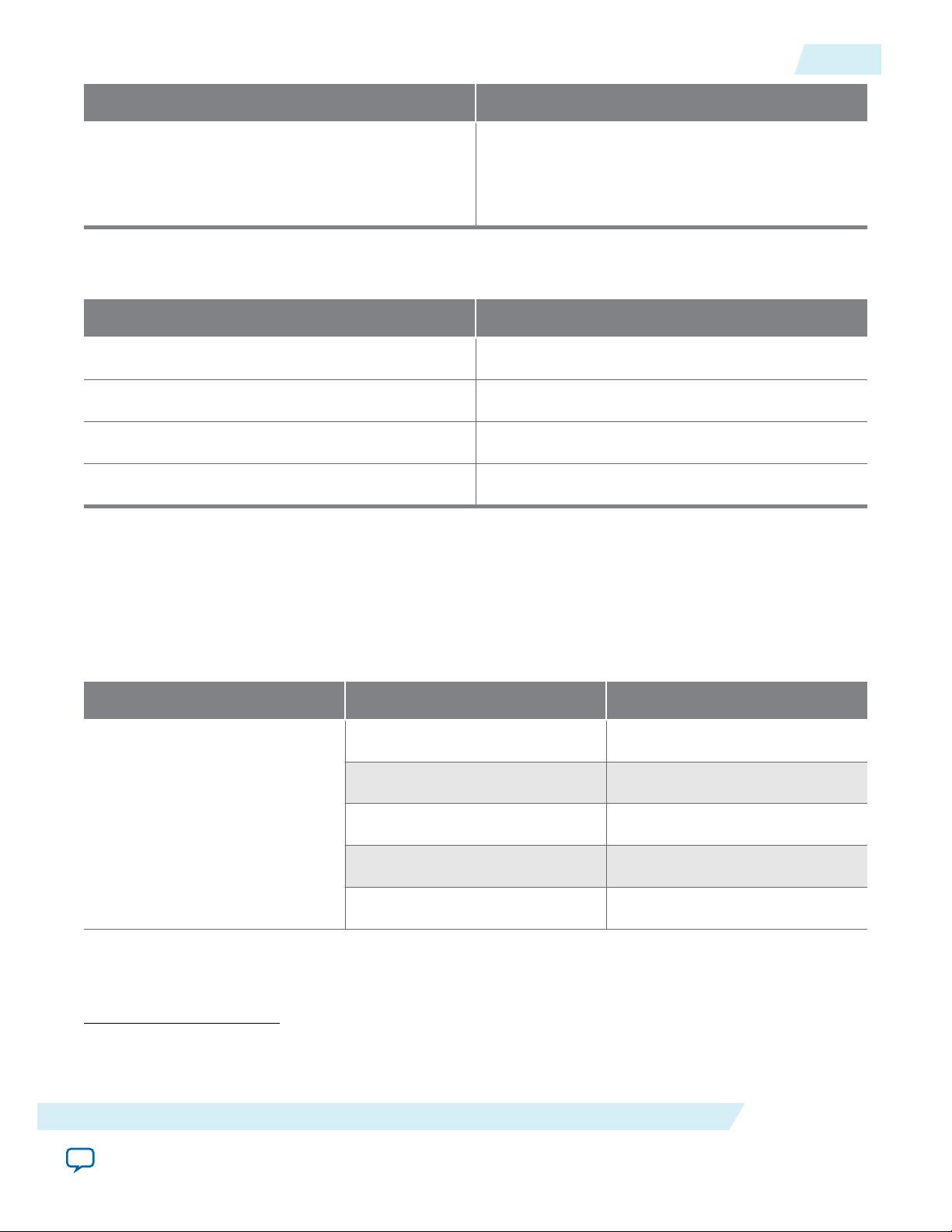
Table 1-3: Slowest Supported Device Speed Grades
Lists the slowest supported device speed grades for different variations of the 40-100GbE IP core.
MegaCore Function Device Family Supported Speed Grades
Arria V GZ I3, C3
Stratix IV (GT) I2
40GbE
Stratix V (GX) I3, C3
Stratix V (GT) I3, C2
Stratix V (GS) I3, C3
(1)
This product does not provide support for Arria 10 devices. For information about Arria 10 40-100GbE
support, refer to the Low Latency 40- and 100-Gbps Ethernet MAC and PHY MegaCore Function User
Guide.
About the 40- and 100-Gbps Ethernet MAC and PHY MegaCore Function
Send Feedback
Altera Corporation
Page 9

1-6
IP Core Verification
MegaCore Function Device Family Supported Speed Grades
40GbE (24.24 Gbps option)
UG-01088
2014.12.15
Arria V GZ I3, C3
Stratix IV (GX) I3, C3
Stratix IV (GT) I3
Stratix V (GX) I3, C3
Stratix V (GT) I3, C2
Stratix V (GS) I3, C3
Stratix V (GX) I3, C3
40GbE (40GBASE-KR4 option)
Stratix V (GT) I3, C2
Stratix V (GS) I3, C3
Arria V GZ I3, C3
Stratix IV (GT) I2
100GbE
Stratix V (GX) I3, C3
Stratix V (GT) I3, C2
Stratix V (GS) I3, C3
100GbE (CAUI–4 option) Stratix V GT C2
IP Core Verification
To ensure functional correctness of the 40-100GbE IP core, Altera performs extensive validation through
both simulation and hardware testing. Before releasing a version of the 40- and 100-Gbps Ethernet MAC
and PHY IP core, Altera runs comprehensive regression tests in the current version of the Quartus® II
software.
Altera verifies that the current version of the Quartus II software compiles the previous version of each IP
core. Any exceptions to this verification are reported in the Altera IP Release Notes. Altera does not verify
compilation with IP core versions older than the previous release.
Related Information
Altera IP Release Notes
Altera Corporation
About the 40- and 100-Gbps Ethernet MAC and PHY MegaCore Function
Send Feedback
Page 10

UG-01088
2014.12.15
Simulation Environment
Altera performs the following tests on the 40-100GbE MAC and PHY IP core in the simulation environ‐
ment using internal and third party standard bus functional models (BFM):
• Constrained random tests that cover randomized frame size and contents
• Randomized error injection tests that inject Frame Check Sequence (FCS) field errors, runt packets,
and corrupt control characters, and then check for the proper response from the IP core
• Assertion based tests to confirm proper behavior of the IP core with respect to the specification
• Extensive coverage of our runtime configuration space and proper behavior in all possible modes of
operation
Hardware Testing
Altera performs hardware testing of the key functions of the 40-100GbE MAC and PHY IP core. The
Altera hardware tests of the 40-100GbE IP core also ensure reliable solution coverage for hardware related
areas such as synchronization, and reset recovery. The IP core is tested with Stratix IV and Stratix V
devices.
Performance and Resource Utilization
Simulation Environment
1-7
The following sections provide performance and resource utilization data for the 40GbE and 100GbE IP
cores.
Resource Utilization for 40GbE IP Cores
Resource utilization changes if the statistics counters are configured in the IP core. You can specify
whether to include or not include the statistics counters in the 40-100GbE parameter editor, but you
cannot change the setting dynamically.
The 24.24 Gbps variations of the 40-100GbE IP core use the same resources as the standard 40GbE IP
core variations. The 40GBASE-KR4 variations require more resources only for the PHY component.
About the 40- and 100-Gbps Ethernet MAC and PHY MegaCore Function
Send Feedback
Altera Corporation
Page 11

1-8
Resource Utilization for 40GbE IP Cores
UG-01088
2014.12.15
Table 1-4: 40GbE IP Core FPGA Resource Utilization in Stratix V and Arria V GZ Devices
Lists the resources and expected performance for selected variations of the 40GbE IP cores in an Arria V GZ or
Stratix V device. The results were obtained using the Quartus II software v13.1 for a Stratix V 5SGXEA7N2F45C2
device.
• Top-level modules are in bold.
• The numbers of ALMs and logic registers are rounded up to the nearest 100.
• The numbers of ALMs, before rounding, are the ALMs needed numbers from the Quartus II Fitter Report.
Memory
Module ALMs Logic Registers
M20K
MAC&PHY with
Avalon-ST client
interface without
statistics counters
MAC&PHY with
Avalon-ST client
interface and with
statistics counters
MAC with Avalon-ST
client interface
without statistics
counters
MAC with Avalon-ST
client interface and
with statistics
counters
• alt_e40_adapter_
rx:adapter_rx
13600 23500 9
17700 30900 9
7100 15000 9
11300 22300 9
500 900 0
• alt_e40_adapter_
tx:adapter_tx
MAC with custom
streaming client
interface without
statistics counters
MAC with custom
streaming client
interface and with
statistics counters
Altera Corporation
300 700 0
6200 13400 9
10400 20700 9
About the 40- and 100-Gbps Ethernet MAC and PHY MegaCore Function
Send Feedback
Page 12

UG-01088
2014.12.15
Resource Utilization for 40GbE IP Cores
Module ALMs Logic Registers
1-9
Memory
M20K
• alt_e40_mac_
3000 7000 9
rx:mac_rx
• alt_e40_mac_
2600 4800 0
tx:mac_tx
• alt_e40_mac_
700 2000 0
csr:mac_csr without
statistics counters
• alt_e40_mac_
4600 8500 0
csr:mac_csr with
statistics counters
PHY 6800 8600 0
• alt_e40_phy_
6200 8200 0
pcs:phy_pcs
• • alt_e40_pcs_
2800 3800 0
rx:pcs_rx
• • alt_e40_pcs_
tx:pcs_tx
• • alt_e40_phy_
csr:phy_csr
• alt_e40_phy_
pma:phy_pma
40GBASE-KR4 PHY
• No auto-negotiation
(AN)
• No link training
(LT)
• Forward error
correction (FEC)
only
• Use M20K blocks
for FEC buffer
2900 3300 0
500 1100 0
200 400 0
14800
16700 8
About the 40- and 100-Gbps Ethernet MAC and PHY MegaCore Function
Send Feedback
Altera Corporation
Page 13

1-10
Resource Utilization for 40GbE IP Cores
Module ALMs Logic Registers
UG-01088
2014.12.15
Memory
M20K
40GBASE-KR4 PHY
23800 24500 8
• AN
• LT
• FEC
• Use M20K blocks
for FEC buffer
40GBASE-KR4 PHY
31900 41600 0
• AN
• LT
• FEC
• Do not use M20K
blocks for FEC
buffer
Table 1-5: 40GbE IP Core FPGA Resource Utilization in Stratix IV Devices
Lists the resources and expected performance for selected variations of the 40GbE IP cores in a Stratix IV device.
The results were obtained using the Quartus II software v13.1 for a Stratix IV EP4S100G5F45C2 device.
• Top-level modules are in bold.
• The numbers of ALMs and logic registers are rounded up to the nearest 100.
Module ALMs Logic Registers
MAC&PHY with
18100 25000 20
Avalon-ST client
interface without
statistics counters
MAC&PHY with
22100 32100 20
Avalon-ST client
interface and with
statistics counters
MAC with Avalon-ST
9700 15200 20
client interface
without statistics
counters
Memory
M9K
Altera Corporation
About the 40- and 100-Gbps Ethernet MAC and PHY MegaCore Function
Send Feedback
Page 14

UG-01088
2014.12.15
Resource Utilization for 40GbE IP Cores
Module ALMs Logic Registers
1-11
Memory
M9K
MAC with Avalon-ST
client interface and
with statistics
counters
• alt_e40_adapter_
rx:adapter_rx
• alt_e40_adapter_
tx:adapter_tx
MAC with custom
streaming client
interface without
statistics counters
MAC with custom
streaming client
interface and with
statistics counters
• alt_e40_mac_
rx:mac_rx
13700 22200 20
700 1000 0
500 800 0
8500 13400 20
12500 20400 20
4300 7000 20
• alt_e40_mac_
3400 4800 0
tx:mac_tx
• alt_e40_mac_
1400 1900 0
csr:mac_csr without
statistics counters
• alt_e40_mac_
5000 8300 0
csr:mac_csr with
statistics counters
PHY 8600 9900 0
• alt_e40_phy_
8100 9400 0
pcs:phy_pcs
• • alt_e40_pcs_
3700 4400 0
rx:pcs_rx
About the 40- and 100-Gbps Ethernet MAC and PHY MegaCore Function
Altera Corporation
Send Feedback
Page 15
1-12
Resource Utilization for 100GbE IP Cores
Module ALMs Logic Registers
UG-01088
2014.12.15
Memory
M9K
• • alt_e40_pcs_
3600 3900 0
tx:pcs_tx
• • alt_e40_phy_
700 1100 0
csr:phy_csr
• alt_e40_phy_pma_
600 500 0
siv:pma
Related Information
Fitter Resources Reports in the Quartus II Help
Information about Quartus II resource utilization reporting, including ALMs needed.
Resource Utilization for 100GbE IP Cores
Resource utilization changes if the statistics counters are configured in the IP core. You can specify
whether to include or not include the statistics counters in the 40-100GbE parameter editor, but you
cannot change the setting dynamically.
Table 1-6: 100GbE IP Core FPGA Resource Utilization in Stratix V and Arria V GZ Devices
Lists the resources and expected performance for selected variations of the 100GbE IP cores in an Arria V GZ or
Stratix V device. The results were obtained using the Quartus II software v13.1 for a Stratix V 5SGXEA7N2F45C2
device.
• Top-level modules are in bold.
• The numbers of ALMs and logic registers are rounded up to the nearest 100.
• The numbers of ALMs, before rounding, are the ALMs needed numbers from the Quartus II Fitter Report.
Memory
Module ALMs Logic Registers
M20K
MAC&PHY with
45100 87700 28
Avalon-ST client
interface without
statistics counters
MAC&PHY with
49700 95500 28
Avalon-ST client
interface and with
statistics counters
Altera Corporation
About the 40- and 100-Gbps Ethernet MAC and PHY MegaCore Function
Send Feedback
Page 16

UG-01088
2014.12.15
Resource Utilization for 100GbE IP Cores
Module ALMs Logic Registers
1-13
Memory
M20K
MAC with Avalon-ST
client interface
without statistics
counters
MAC with Avalon-ST
client interface and
with statistics
counters
• alt_e100_adapter_
rx:adapter_rx
• alt_e100_adapter_
tx:adapter_tx
MAC with custom
streaming client
interface without
statistics counters
MAC with custom
streaming client
interface and with
statistics counters
21600 45200 28
26100 53000 28
2700 6600 17
2600 4900 0
16200 33700 11
20700 41500 11
• alt_e100_mac_
6500 14900 11
rx:mac_rx
• alt_e100_mac_
9200 17500 0
tx:mac_tx
• alt_e100_mac_
700 2000 0
csr:mac_csr without
statistics counters
• alt_e100_mac_
4700 8500 0
csr:mac_csr with
statistics counters
PHY 23500 42500 0
About the 40- and 100-Gbps Ethernet MAC and PHY MegaCore Function
Send Feedback
Altera Corporation
Page 17

1-14
Resource Utilization for 100GbE IP Cores
Module ALMs Logic Registers
UG-01088
2014.12.15
Memory
M20K
• alt_e100_phy_
23000 41700 0
pcs:phy_pcs
• • alt_e100_pcs_
13600 26300 0
rx:pcs_rx
• • alt_e100_pcs_
8700 13700 0
tx:pcs_tx
• • alt_e100_phy_
700 1700 0
csr:phy_csr
• alt_e100_phy_pma_
500 800 0
sv:pma
Table 1-7: 100GbE IP Core FPGA Resource Utilization in Stratix IV Devices
Lists the resources and expected performance for selected variations of the 100GbE IP cores in a Stratix IV device.
The results were obtained using the Quartus II software v13.1 for a Stratix IV EP4S100G5F45C2 device.
• Top-level modules are in bold.
• The numbers of ALMs and logic registers are rounded up to the nearest 100.
Module ALMs Logic Registers
MAC&PHY with
60300 96000 29
Avalon-ST client
interface without
statistics counters
MAC&PHY with
65200 102400 29
Avalon-ST client
interface and with
statistics counters
MAC with Avalon-ST
30700 48600 29
client interface
without statistics
counters
Memory
M9K
Altera Corporation
About the 40- and 100-Gbps Ethernet MAC and PHY MegaCore Function
Send Feedback
Page 18

UG-01088
2014.12.15
Resource Utilization for 100GbE IP Cores
Module ALMs Logic Registers
1-15
Memory
M9K
MAC with Avalon-ST
client interface and
with statistics
counters
• alt_e100_adapter_
rx:adapter_rx
• alt_e100_adapter_
tx:adapter_tx
MAC with custom
streaming client
interface without
statistics counters
MAC with custom
streaming client
interface and with
statistics counters
• alt_e100_mac_
rx:mac_rx
35600 55000 29
4100 6300 17
3900 6400 0
23300 35900 12
26900 42300 12
9500 15600 12
• alt_e100_mac_
12600 18400 0
tx:mac_tx
• alt_e100_mac_
1200 1900 0
csr:mac_csr without
statistics counters
• alt_e100_mac_
4900 8300 0
csr:mac_csr with
statistics counters
PHY 8600 9900 0
• alt_e100_phy_
2900 46900 0
pcs:phy_pcs
• • alt_e100_pcs_
16700 28500 0
rx:pcs_rx
About the 40- and 100-Gbps Ethernet MAC and PHY MegaCore Function
Altera Corporation
Send Feedback
Page 19
1-16
Resource Utilization for 100GbE CAUI–4 IP Cores
Module ALMs Logic Registers
UG-01088
2014.12.15
Memory
M9K
• • alt_e100_pcs_
11200 16600 0
tx:pcs_tx
• • alt_e100_phy_
1100 1700 0
csr:phy_csr
• alt_e100_phy_pma_
600 500 0
siv:pma
In the standard 100GbE variations, as in the 40GbE variations, some resource utilization numbers
decrease when statistics counters are not configured in the IP core. For example, compare the values for
the MAC with custom streaming client interface on a Stratix IV device with statistics counters included or
not included. When counters are included, the MAC requires 26600 ALMs, but when the counters are not
included, the MAC requires 23000 ALMs. The difference is 3600 ALMs. In a Stratix V device, the
difference is 2900 ALMs.
Related Information
Fitter Resources Reports in the Quartus II Help
Information about Quartus II resource utilization reporting, including ALMs needed.
Resource Utilization for 100GbE CAUI–4 IP Cores
Resource utilization changes if the statistics counters are configured in the IP core. You can specify
whether to include or not include the statistics counters in the 40-100GbE parameter editor, but you
cannot change the setting dynamically.
Table 1-8: 100GbE CAUI–4 IP Core FPGA Resource Utilization
Lists the resources and expected performance for selected variations of the 100GbE CAUI-4 IP core with statistics
counters included or not included. The results were obtained using the Quartus II software v13.1 for a Stratix V
5SGTMC7K2F40C2 device.
• Top-level modules are in bold.
• The numbers of ALMs and logic registers are rounded up to the nearest 100.
• The numbers of ALMs, before rounding, are the ALMs needed numbers from the Quartus II Fitter Report.
Memory
Module ALMs Logic Registers
M20K
MAC&PHY with
50100 102700 28
Avalon-ST client
interface without
statistics counters
Altera Corporation
About the 40- and 100-Gbps Ethernet MAC and PHY MegaCore Function
Send Feedback
Page 20

UG-01088
2014.12.15
Resource Utilization for 100GbE CAUI–4 IP Cores
Module ALMs Logic Registers
1-17
Memory
M20K
MAC&PHY with
Avalon-ST client
interface and with
statistics counters
MAC with Avalon-ST
client interface
without statistics
counters
MAC with Avalon-ST
client interface and
with statistics
counters
• alt_e100_adapter_
rx:adapter_rx
• alt_e100_adapter_
tx:adapter_tx
MAC with custom
streaming client
interface without
statistics counters
54600 110100 28
21500 45100 28
26100 52800 28
2700 6500 17
2600 4900 0
16200 33700 11
MAC with custom
20700 41300 11
streaming client
interface and with
statistics counters
• alt_e100_mac_
6500 14800 11
rx:mac_rx
• alt_e100_mac_
9200 17400 0
tx:mac_tx
• alt_e100_mac_
700 2000 0
csr:mac_csr without
statistics counters
About the 40- and 100-Gbps Ethernet MAC and PHY MegaCore Function
Send Feedback
Altera Corporation
Page 21

1-18
Release Information
Module ALMs Logic Registers
UG-01088
2014.12.15
Memory
M20K
• alt_e100_mac_
4600 8500 0
csr:mac_csr with
statistics counters
PHY 28600 57400 0
• alt_e100_phy_pcs_
27200 55000 0
caui4:phy_pcs
• • alt_e100_pcs_
18000 35700 0
rx_caui4:pcs_rx
• • alt_e100_pcs_
8400 17500 0
tx_caui4:pcs_tx
• • alt_e100_phy_
700 1700 0
csr_caui4:phy_
csr
• alt_e100_phy_pma_
1400 2500 0
sv_caui4:pma
Related Information
Fitter Resources Reports in the Quartus II Help
Information about Quartus II resource utilization reporting, including ALMs needed.
Release Information
Table 1-9: 40‑100GbE IP Core Current Release Information
Item Description
Version 14.1
Release Date 2014.12.15
Altera Corporation
About the 40- and 100-Gbps Ethernet MAC and PHY MegaCore Function
Send Feedback
Page 22

UG-01088
2014.12.15
Item Description
Ordering Codes IP-40GEMAC
IP-40GEPHY
IP-100GEMAC
IP-100GEPHY
IP-40GEMACPHY
IP-100GEMACPHY
IP-40GBASEKR4PHY
Product ID 40Gb Ethernet MAC: 00DF
40Gb Ethernet PHY: 00E0
100Gb Ethernet MAC: 00DD
100Gb Ethernet PHY: 00DE
40GBASE-KR4 with FEC: 0113
Release Information
1-19
Vendor ID 6AF7
About the 40- and 100-Gbps Ethernet MAC and PHY MegaCore Function
Send Feedback
Altera Corporation
Page 23

2014.12.15
www.altera.com
101 Innovation Drive, San Jose, CA 95134
Getting Started
2
UG-01088
Subscribe
Send Feedback
The following sections explain how to install, parameterize, simulate, and initialize the 40-100GbE IP
core:
Installing and Licensing IP Cores on page 2-2
The 40-100GbE IP core is available with the Quartus II software in the Altera MegaCore IP Library.
Specifying the 40-100GbE IP Core Parameters and Options on page 2-3
The 40-100GbE IP core supports a standard customization and generation process from the Quartus II IP
Catalog.. This IP core is not supported in Qsys.
IP Core Parameters on page 2-3
The 40-100GbE parameter editor provides the parameters you can set to configure the 40-100GbE IP core
and simulation testbenches.
Files Generated for the 40-100GbE IP Core on page 2-10
The Quartus II software version 14.1 generates the following output for your 40-100GbE IP core.
Simulating the IP Core on page 2-10
Integrating Your IP Core in Your Design on page 2-11
40-100GbE IP Core Testbenches on page 2-14
Altera provides a testbench and an example design with most variations of the 40-100GbE IP core. The
testbench is available for simulation of your IP core, and the example design targets a C2 speed grade
device and can be run on hardware. You can run the testbench to observe the IP core behavior on the
various interfaces in simulation.
Simulating the 40-100GbE IP Core With the Testbenches on page 2-20
Compiling the Full Design and Programming the FPGA on page 2-24
Initializing the IP Core on page 2-24
Related Information
Managing Quartus II Projects
Refer to the "Integrating IP Cores" section of this Quartus II Handbook chapter for more information
about generating an Altera IP core and integrating it in your Quartus II project.
©
2014 Altera Corporation. All rights reserved. ALTERA, ARRIA, CYCLONE, ENPIRION, MAX, MEGACORE, NIOS, QUARTUS and STRATIX words and logos are
trademarks of Altera Corporation and registered in the U.S. Patent and Trademark Office and in other countries. All other words and logos identified as
trademarks or service marks are the property of their respective holders as described at www.altera.com/common/legal.html. Altera warrants performance
of its semiconductor products to current specifications in accordance with Altera's standard warranty, but reserves the right to make changes to any
products and services at any time without notice. Altera assumes no responsibility or liability arising out of the application or use of any information,
product, or service described herein except as expressly agreed to in writing by Altera. Altera customers are advised to obtain the latest version of device
specifications before relying on any published information and before placing orders for products or services.
ISO
9001:2008
Registered
Page 24

acds
quartus - Contains the Quartus II software
ip - Contains the Altera IP Library and third-party IP cores
altera - Contains the Altera IP Library source code
<IP core name> - Contains the IP core source files
2-2
Installing and Licensing IP Cores
Installing and Licensing IP Cores
The Altera IP Library provides many useful IP core functions for production use without purchasing an
additional license. You can evaluate any Altera IP core in simulation and compilation in the Quartus II
software using the OpenCore® evaluation feature. Some Altera IP cores, such as MegaCore functions,
require that you purchase a separate license for production use. You can use the OpenCore Plus feature to
evaluate IP that requires purchase of an additional license until you are satisfied with the functionality and
performance. After you purchase a license, visit the Self Service Licensing Center to obtain a license
number for any Altera product.
Figure 2-1: IP Core Installation Path
UG-01088
2014.12.15
Note: The default IP installation directory on Windows is <drive>:\altera\<version number>; on Linux it is
<home directory>/altera/ <version number>.
Related Information
• Altera Licensing Site
• Altera Software Installation and Licensing Manual
OpenCore Plus IP Evaluation
Altera's free OpenCore Plus feature allows you to evaluate licensed MegaCore IP cores in simulation and
hardware before purchase. You need only purchase a license for MegaCore IP cores if you decide to take
your design to production. OpenCore Plus supports the following evaluations:
• Simulate the behavior of a licensed IP core in your system.
• Verify the functionality, size, and speed of the IP core quickly and easily.
• Generate time-limited device programming files for designs that include IP cores.
• Program a device with your IP core and verify your design in hardware
OpenCore Plus evaluation supports the following two operation modes:
• Untethered—run the design containing the licensed IP for a limited time.
• Tethered—run the design containing the licensed IP for a longer time or indefinitely. This requires a
connection between your board and the host computer.
All IP cores that use OpenCore Plus time out simultaneously when any IP core in the design times
Note:
out.
Altera Corporation
Getting Started
Send Feedback
Page 25

UG-01088
2014.12.15
Specifying the 40-100GbE IP Core Parameters and Options
Specifying the 40-100GbE IP Core Parameters and Options
The 40-100GbE parameter editor allows you to quickly configure your custom IP variation. Use the
following steps to specify IP core options and parameters in the Quartus II software.
1. In the IP Catalog (Tools > IP Catalog), locate and double-click the name of the IP core to customize.
The parameter editor appears.
2. Specify a top-level name for your custom IP variation. The parameter editor saves the IP variation
settings in a file named <your_ip>.qsys. Click OK.
3. Specify the parameters and options for your IP variation in the parameter editor, including one or
more of the following. Refer to your IP core user guide for information about specific IP core
parameters.
• Specify parameters defining the IP core functionality, port configurations, and device-specific
features.
• Specify options for processing the IP core files in other EDA tools.
4. Generate the IP core by following these steps:
a. Click Generate.
b. Optionally, to generate a simulation testbench or example project, follow the instructions in
Generating the 40-100GbE Testbench on page 2-21.
5. Click Finish. The parameter editor adds the top-level .qsys file to the current project automatically. If
you are prompted to manually add the .qsys file to the project, click Project > Add/Remove Files in
Project to add the file.
6. After generating and instantiating your IP variation, make appropriate pin assignments to connect
ports.
2-3
IP Core Parameters
The 40-100GbE parameter editor provides the parameters you can set to configure the 40-100GbE IP core
and simulation testbenches.
The 40-100GbE parameter editor has two tabs, the Main tab and the 40GBASE-KR4 tab. The 40GBASE-
KR4 tab in the 40-100GbE parameter editor is relevant only for certain variations that target a Stratix V
device; for other variations, the parameters on the tab are unavailable.
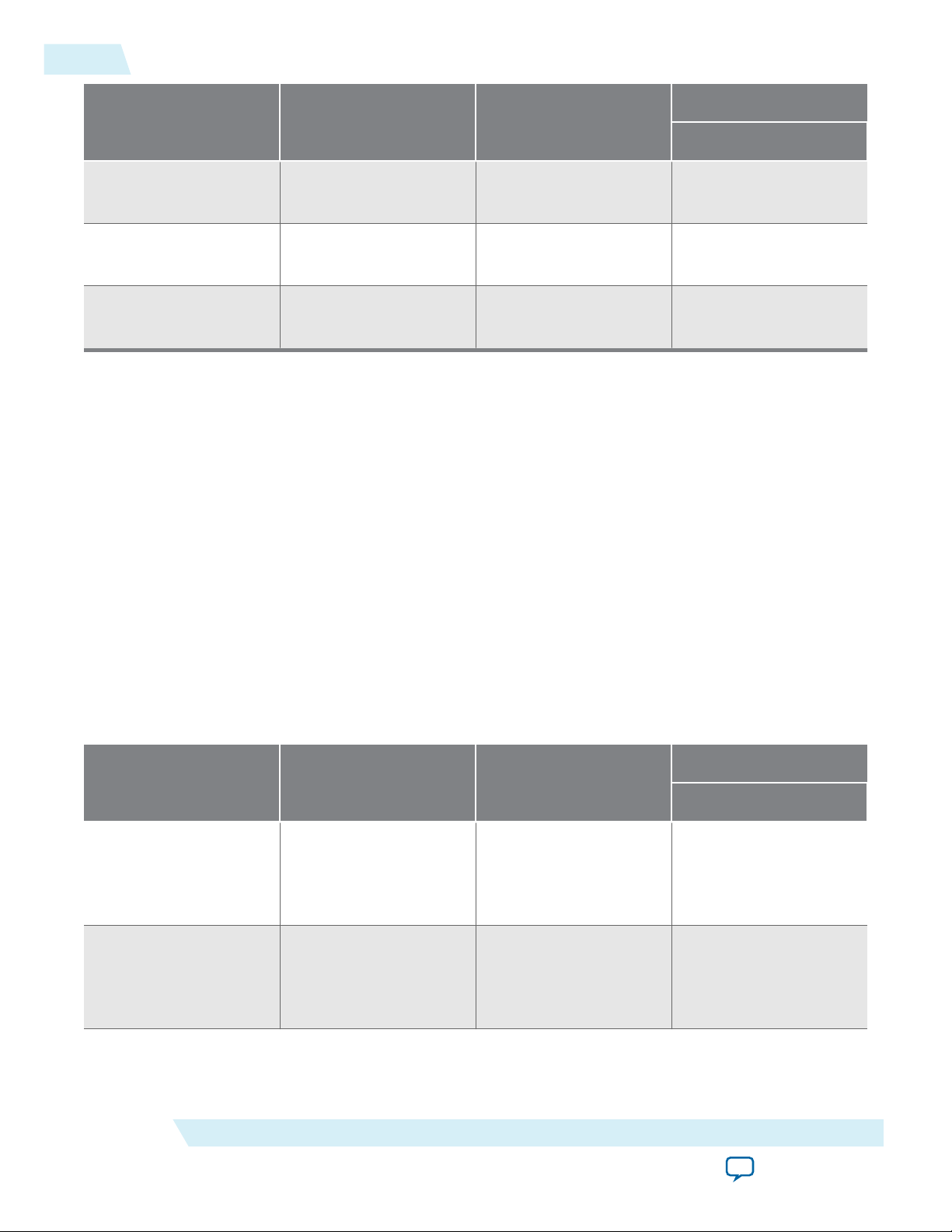
Table 2-1: 40-100GbE Parameters: Main Tab
Describes the parameters for customizing the 40-100GbE IP core, on the Main tab of the 40-100GbE parameter
editor.
Parameter Type Range Default Setting Parameter Description
General Design Options
Device family String • Stratix IV
• Stratix V
• Arria V GZ
Stratix V Selects the device family.
Getting Started
Send Feedback
Altera Corporation
Page 26

2-4
IP Core Parameters
Parameter Type Range Default Setting Parameter Description
UG-01088
2014.12.15
MAC configu‐
ration
String • 40 GbE
• 100 GbE
Core options String • PHY
• MAC
• MAC & PHY
PHY configu‐
ration
(2) (3) (4)
Integer 40 GbE:
• 24.24 Gbps
(4x6.25)
• 40 Gbps (4x10)
100 GbE:
• 100 Gbps
(10x10)
• CAUI-4 (4x25)
MAC client
interface
(5)
String • Custom–ST
interface
• Avalon–ST
interface
100 GbE Selects the MAC datapath width.
MAC & PHY Selects the core components to
generate.
The default value
depends on the
Selects the Ethernet speed and lane
configuration.
MAC configura‐
tion value.
40 GbE:
• 40 Gbps (4x10)
100 GbE:
• 100 Gbps
(10x10)
Avalon–ST
interface
Selects the Avalon–ST interface or
the narrower, custom streaming
client interface to the MAC.
Duplex mode
(6)
Integer • RX
• TX
Full Duplex Selects datapath mode to generate.
• Full Duplex
PHY Configuration Options
PHY PLL type
(2) (7) (8)
(2)
This parameter is disabled in MAC-only operation.
(3)
The PHY configuration parameter is disabled when MAC configuration is set to 100GbE and Device
String • ATX
• CMU
ATX Configures the PHY PLL.
family is not Stratix V. If the parameter is disabled, the IP core must always be set to the regular 10 Gbps
PHY link option of 4 x 10.3125 or 10 x 10.3125.
(4)
For the Device family parameter, the CAUI-4 option requires the Stratix V GT device.
(5)
This parameter is disabled in PHY-only operation.
(6)
The Duplex mode parameter is disabled when PHY configuration is set to CAUI–4; CAUI–4 variations
must always be set to the duplex configuration.
(7)
The PHY PLL type parameter is disabled when PHY configuration is set to CAUI–4; CAUI–4 variations
must always be set to the ATX configuration.
(8)
The PHY PLL type parameter is disabled when the IP core targets a Stratix IV device; Stratix IV variations
must always be set to the CMU configuration.
Altera Corporation
Getting Started
Send Feedback
Page 27

UG-01088
2014.12.15
IP Core Parameters
Parameter Type Range Default Setting Parameter Description
2-5
PHY reference
frequency
(2)
Integer
(encodi
ng)
Advanced Design Options
Status clock
(2)
rate
Statistics
counters
(5)
Float • Stratix IV:
Boolean • True
The range and default settings depend
on the PHY configuration.
Despite its apparent availability in the
parameter editor, CAUI–4 variations
do not support the 322.265625 MHz
clock frequency. For correct
functioning of CAUI–4 variations, you
must set this parameter to the value of
644.53125 MHz.
• Stratix IV: 37.5
37.5–50.0
• Arria V GZ or
• Arria V GZ or
Stratix V: 100.0
Stratix V:
100.0–125.0
True If turned on, the IP core includes
• False
Sets the expected incoming PHY
clk_ref reference frequency. The
input clock frequency must match
the frequency you specify for this
parameter.
In Sync-E variations, the input clock
frequencies for the rx_ref_clk and
tx_ref_clk clocks must match the
frequency you specify for this
parameter, although the two clocks
can be driven from different sources
and need not be aligned with each
other.
Sets the clock rate of clk_status in
MHz.
built–in statistics counters. If turned
off, the IP core is configured without
statistics counters.
Enable SyncE
support
Getting Started
Boolean • True
• False
False Enables or disables a separate
reference clock for the RX CDR
block in the transceiver and exposes
the RX recovered clock as an output
signal. If this option is turned on
(set to true), the TX PLL and the RX
CDR in the transceiver have
separate input reference clocks and
the RX recovered clock is visible as
an IP core output signal. If it is
turned off, the two PLLs share one
input reference clock and the RX
recovered clock is not available as an
output signal.
Altera Corporation
Send Feedback
Page 28

2-6
IP Core Parameters
UG-01088
2014.12.15
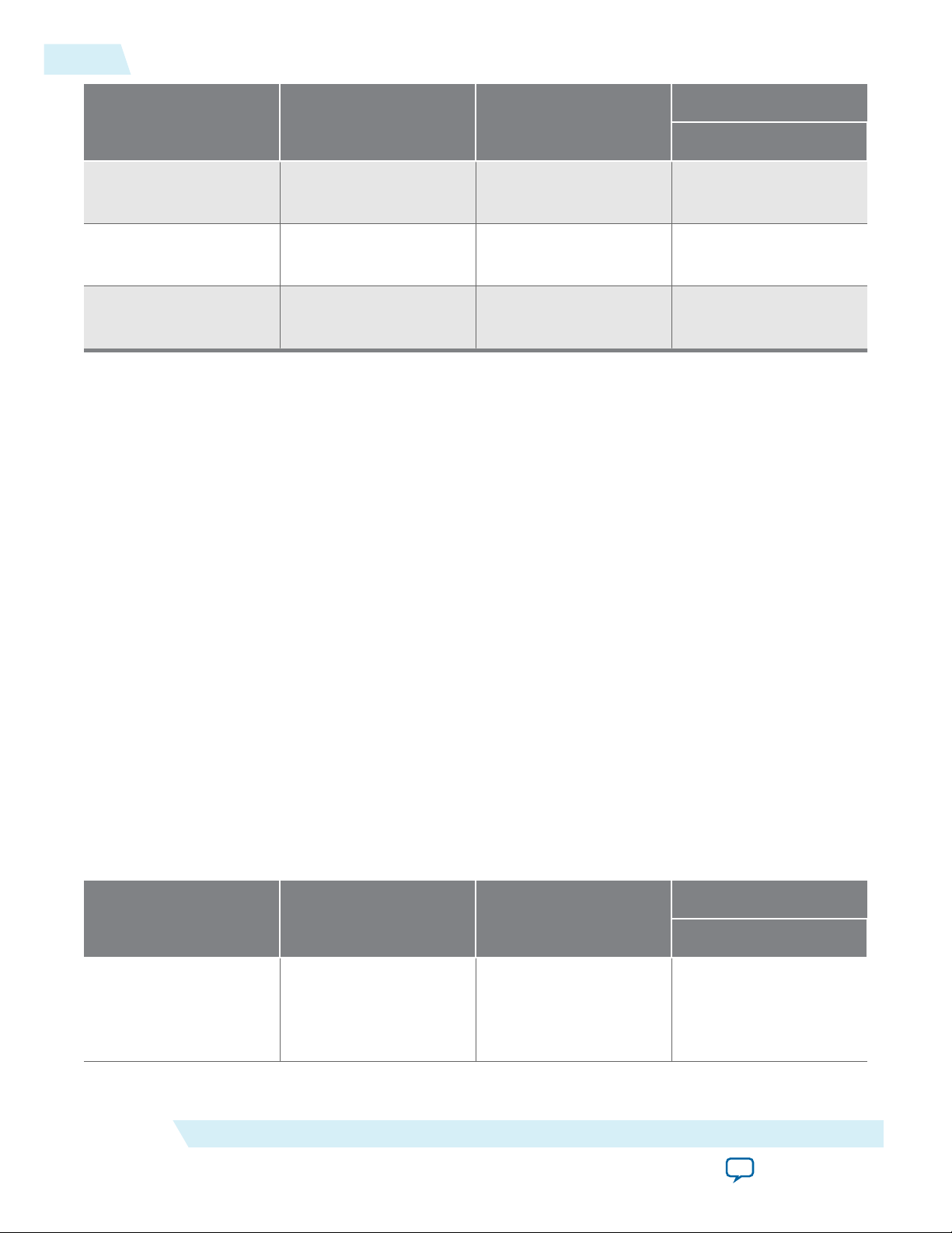
Table 2-2: 40-100GbE Parameters: 40GBASE-KR4 Tab
Describes the parameters for customizing a 40GBASE-KR4 40-100GbE IP core, on the 40GBASE-KR4 tab of the
40-100GbE parameter editor. The parameters on this tab are available only if the following conditions hold:
• Your IP core targets a Stratix V device. You set the target device family for your Quartus II project or in the
Quartus II software before you acess the IP Catalog.
• You select the value of 40 GbE for the MAC configuration parameter on the Main tab.
• You select a Core option value that includes a PHY component (PHY or MAC & PHY) on the Main tab.
• You select the value of 40 Gbps (4x10) for the PHY configuration parameter on the Main tab.
• You select the value of Full Duplex for the Duplex mode parameter on the Main tab.
Parameter Type Range Default
Setting
KR4 General Options
Enable KR4 Boolean • True
False If this parameter is turned on, the IP core is a
• False
Enable KR4
Reconfigura‐
Boolean • True
• False
True If this parameter is turned on, the IP core supports
tion
Auto-Negotiation
Enable AutoNegotiation
Boolean • True
• False
True If this parameter is turned on, the IP core includes
Parameter Description
40GBASE-KR4 variation. If this parameter is turned
off, the IP core is not a 40GBASE-KR4 variation, and
the other parameters on this tab are not available.
dynamic analog reconfiguration through a dedicated
reconfiguration interface. If this parameter is turned
off, the IP core cannot support auto-negotiation (AN)
or link training (LT) modes, and the AN and LT
parameters on this tab are not available. This
parameter does not affect FEC availability.
logic to implement auto-negotiation as defined in
Clause 73 of IEEE Std 802.3ap–2007. If this parameter
is turned off, the IP core does not include autonegotiation logic and cannot perform auto-negotia‐
tion.
Link fail inhibit
time for 40Gb
Ethernet
Altera Corporation
Integer
(Unit:
ms)
Currently the IP core can only negotiate to KR4
mode.
500–510ms504 ms Specifies the time before link_status is set to FAIL
or OK. A link fails if the time duration specified by
this parameter expires before link_status is set to
OK. For more information, refer to Clause 73 Auto-
Negotiation for Backplane Ethernet in IEEE Standard
802.3ap–2007.
The 40GBASE-KR4 IP core asserts the lanes_
deskewed signal to indicate link_status is OK.
Getting Started
Send Feedback
Page 29

UG-01088
2014.12.15
IP Core Parameters
2-7
Parameter Type Range Default
Setting
Auto-Negotia‐
tion Master
String • Lane 0
• Lane 1
Lane 0 Selects the master channel for auto-negotiation.
• Lane 2
• Lane 3
Pause ability–C0Boolean • True
True If this parameter is turned on, the IP core supports
• False
Pause ability–C1Boolean • True
True If this parameter is turned on, the IP core supports
• False
Link Training: PMA Parameters
VMAXRULE Integer
VMINRULE Integer
0–63 60
0–63 9
Parameter Description
symmetric pauses as defined in Annex 28B of Section
2 of IEEE Std 802.3–2008.
asymmetric pauses as defined in Annex 28B of
Section 2 of IEEE Std 802.3–2008.
Specifies the maximum VOD. The default value, 60,
represents 1200 mV.
Specifies the minimum VOD. The default value, 9,
represents 165 mV.
VODMINRULE Integer
VPOSTRULE Integer
VPRERULE Integer
PREMAINVAL Integer
PREPOSTVAL Integer
PREPREVAL Integer
INITMAINVAL Integer
0–63 24
0–31 31
0–15 15
0–63 60
0–31 0
0–15 0
0–63 52
Specifies the minimum VOD for the first tap. The
default value, 24, represents 440 mV.
Specifies the maximum value that the internal
algorithm for pre-emphasis will ever test in
determining the optimum post-tap setting.
Specifies the maximum value that the internal
algorithm for pre-emphasis will ever test in
determining the optimum pre-tap setting.
Specifies the Preset VOD value. This value is set by the
Preset command of the link training protocol,
defined in Clause 72.6.10.2.3.1 of IEEE Std 802.3ap–
2007.
Specifies the preset Post-tap value.
Specifies the preset Pre-tap value.
Specifies the initial VOD value. This value is set by the
Initialize command of the link training protocol,
defined in Clause 72.6.10.2.3.2 of IEEE Std 802.3ap–
2007.
INITPOSTVAL Integer
Getting Started
Send Feedback
0–31 30
Specifies the initial Post-tap value.
Altera Corporation
Page 30

2-8
IP Core Parameters
UG-01088
2014.12.15
Parameter Type Range Default
Setting
INITPREVAL Integer
0–15 5
Link Training: General
Enable Link
Training
Enable
microcessor
Boolean • True
• False
Boolean • True
• False
True If this parameter is turned on, the IP core includes
False If this parameter is turned on, the IP core includes a
interface
Enable RX
equalization
Boolean • True
• False
False If this parameter is turned on, the IP core includes
Parameter Description
Specifies the initial Pre-tap value.
the link training module, which configures the
remote link partner TX PMD for the lowest Bit Error
Rate (BER). LT is defined in Clause 72 of IEEE Std
802.3ap–2007.
dedicated interface through which you can control
the link training.
the RX part of the link training module. This part of
the link training configures local receiver RX
Continuous Linear Time Equalizer (CTLE) and
Decision Feedback Equalizer (DFE) to achieve the
lowest Bit Error Rate (BER) .
Maximum bit
error count
Number of
frames to send
before sending
actual data
Integer
2n – 1 for
n an
integer in
the range
4–12.
Integer • 127
• 255
4095
127
Specifies the maximum number of errors on a lane
before the Link Training Error bit (40GBASEKR4 register offset 0xD2, bit 4, 12, 20, or 28,
depending on the lane) is set, indicating an unaccept‐
able bit error rate.
n is the width of the Bit Error Counter that is
configured in the IP core. The value to which you set
this parameter determines n, and thus the width of
the Bit Error Counter. Because the default value of
this parameter is 4095, the default width of the Bit
Error Counter is 12 bits.
You can use this parameter to tune PMA settings. For
example, if you see no difference in error rates
between two different sets of PMA settings, you can
increase the width of the bit error counter to
determine if a larger counter enables you to
distinguish between PMA settings.
Specifies the number of additional training frames
the local link partner delivers to ensure that the link
partner can correctly detect the local receiver state.
FEC Options
Altera Corporation
Getting Started
Send Feedback
Page 31

UG-01088
2014.12.15
IP Core Parameters
2-9
Parameter Type Range Default
Setting
Include FEC
sublayer
Set FEC_ability
bit on power
Boolean • True
• False
Boolean • True
• False
False If this parameter is turned on, the IP core includes
True
up/reset
Set FEC_Enable
bit on power
Boolean • True
• False
True
up/reset
Set FEC_Error_
indication_
Boolean • True
• False
True
ability bit on
power up/reset
Use M20K for
FEC Buffer (if
Boolean • True
• False
True
available)
Parameter Description
logic to implement FEC.
If this parameter is turned on, the IP core sets the
FEC ability bit (40GBASE-KR4 register offset 0xB0,
bit 16) on power up and reset.
If this parameter is turned on, the IP core sets the
FEC enable bit (40GBASE-KR4 register offset 0xB0,
bit 18) on power up and reset. If you turn on this
parameter but do not turn on Set FEC_ability bit on
power up/reset, this parameter has no effect: the IP
core cannot specify the value of 1 for FEC Requested
without specifying the value of 1 for FEC Ability.
If this parameter is turned on, the IP core is
programmed by default (40GBASE-KR4 register
offset 0xB0, bit 17) to report decoding errors to the
PCS.
If this parameter is turned on, the IP core is
configured with a pipelined FEC buffer to support the
Quartus II software in inferring M20K memory.
Turning on this parameter potentially saves device
resources.
Table 2-3: 40-100GbE PHY Parameter Settings
Lists the PHY parameters that are configured automatically based on parameter values you select in the 40G/100G
Ethernet parameter editor.
Parameter 40GbE Value
40GBASE-KR4 Value
Lanes
Data rate per lane
Available PHY
4 10 4 4
10312.5 Mbps 10312.5 Mbps 6250.0 Mbps 25781.25 Mbps
644.53125 MHz
100GbE Value 40GbE at 24.24 Gbps 100GbE at CAUI–4
644.53125 MHz
390.625 MHz
644.53125 MHz
reference clock
frequencies
Related Information
322.265625 MHz
322.265625 MHz
195.3125 MHz
• Clocks on page 3-51
The range and default settings for the PHY reference frequency parameter depend on the PHY
configuration parameter value. The PHY reference frequency value is the required frequency of the
transceiver reference clock or transceiver reference clocks.
Getting Started
Send Feedback
Altera Corporation
Page 32

Notes:
1. If generated for your IP variation
<Project Directory >
<your_ip>_sim
<simulator_vendor >
<simulator setup scripts>
<your_ip>.qip - Quartus II IP integration file
<your_ip>.sip - Lists files for simulation
<your_ip>_example - Testbench and example project
1
<your_ip>.v, .sv, or .vhd - Top-level IP synthesis file
<tyour_ip>.v
<your_ip>_syn.v or .vhd - Timing & resource estimation netlist
1
<your_ip>.cmp - VHDL component declaration file
<your_ip>.bsf - Block symbol schematic file
<your_ip> - IP core synthesis files
<your_ip>.sv, .v, or .vhd - HDL synthesis files
<your_ip>.sdc - Timing constraints file
<your_ip>.ppf - XML I/O pin information file
<your_ip>.spd - Combines individual simulation scripts
<your_ip>_sim.f - Refers to simulation models and scripts
2-10
Files Generated for the 40-100GbE IP Core
• 40-100GbE IP Core Testbenches on page 2-14
Provides a list of IP core variations (parameter value choices) for which the Quartus II software can
generate a testbench and example design if you turn on Generate example design.
Files Generated for the 40-100GbE IP Core
The Quartus II software version 14.1 generates the following output for your 40-100GbE IP core.
Figure 2-2: IP Core Generated Files
UG-01088
2014.12.15
Simulating the IP Core
Altera Corporation
You can simulate your 40GbE or 100GbE IP core variation with the functional simulation model and the
testbench or example design generated with the IP core. The functional simulation model is a cycleaccurate model that allows for fast functional simulation of your IP core instance using industry-standard
VHDL or Verilog HDL simulators. If your IP core variation does not generate a matching testbench, you
can create your own testbench to exercise the IP core functional simulation model.
The functional simulation model and testbench files are generated in project subdirectories. These
directories also include scripts to compile and run the example design.
Note:
Use the simulation models only for simulation and not for synthesis or any other purposes. Using
these models for synthesis creates a nonfunctional design.
Getting Started
Send Feedback
Page 33

UG-01088
2014.12.15
Integrating Your IP Core in Your Design
2-11
In the top-level wrapper file for your simulation project, you can set the FAST_SIMULATION parameter to
enable simulation optimization. Parameters are set through the IP core parameter editor. In general, you
should not change them manually. The only exception is the FAST_SIMULATION parameter. You should set
the FAST_SIMULATION parameter on the PHY blocks by adding the following line to the top-level wrapper
file:
defparam <dut instance>.FAST_SIMULATION = 1;
Note: You can use the example testbench as a guide for setting the simulation parameters in your own
simulation environment. This line is already present in the Altera-provided testbench that is
generated with the IP core.
Related Information
• Simulating the 40-100GbE IP Core With the Testbenches on page 2-20
Instructions to simulate the 40GbE or 100GbE IP core with the IP core appropriate testbench you can
generate.
• 40-100GbE IP Core Testbenches on page 2-14
Altera provides a testbench and example design with most variations of the 40-100GbE IP core. The
testbench is available for simulation of your IP core, and the example design can be run on hardware.
This topic describes the testbench provided with the 40-100GbE IP core. For a complete list of models
or libraries required to simulate your IP core, refer to the scripts provided with the testbench.
• Simulating Altera Designs
Chapter in volume 3 of the Quartus II Handbook that provides information about simulating Altera IP
cores.
Integrating Your IP Core in Your Design
When you integrate your IP core instance in your design, you must pay attention to the following items:
Pin Assignments on page 2-11
External Transceiver Reconfiguration Controller on page 2-11
Placement Settings for the 40-100GbE IP Core on page 2-14
Pin Assignments
When you integrate your 40-100GbE IP core instance in your design, you must make appropriate pin
assignments. You can create a virtual pin to avoid making specific pin assignments for top-level signals
while you are simulating and not ready to map the design to hardware.
Related Information
Quartus II Help
For information about the Quartus II software, including virtual pins and the IP Catalog.
External Transceiver Reconfiguration Controller
40-100GbE IP cores that include the PHY component require an external reconfiguration controller to
compile and to function correctly in hardware.
Getting Started
Send Feedback
Altera Corporation
Page 34

2-12
External Transceiver Reconfiguration Controller
You can use the IP Catalog to generate an Altera transceiver reconfiguration controller.
• For Arria V GZ and Stratix V devices, select the Transceiver Reconfiguration Controller.
• For Stratix IV devices, select the ALTGX_RECONFIG transceiver reconfiguration block.
When you configure the Altera Transceiver Reconfiguration Controller, you must specify the number of
reconfiguration interfaces. The number of reconfiguration interfaces required for the 40GbE and 100GbE
IP cores depends on the IP core variation.
Table 2-4: Number of Reconfiguration Interfaces
Lists the number of reconfiguration interfaces you should specify for the Altera Transceiver Reconfiguration
Controller for your Arria V GZ or Stratix V 40-100GbE IP core that includes a PHY component.
PHY Configuration RX Only TX Only Duplex
UG-01088
2014.12.15
Standard 40GbE and
4 8 8
40GBASE-KR4
(4x10.3125 lanes)
100GbE (10x10.3125
10 20 20
lanes)
CAUI-4 (4x25.78125
— — 4x3
(9)
lanes)
You can configure your reconfiguration controller with additional interfaces if your design connects with
multiple transceiver IP cores. You can leave other options at the default settings or modify them for your
preference.
You should connect the reconfig_to_xcvr and reconfig_from_xcvr ports of the 40-100GbE IP core to
the corresponding ports of the reconfiguration controller.
The CAUI–4 variations have four reconfiguration channels, numbered consecutively from
reconfig_to_xcvr0 and reconfig_from_xcvr0 to reconfig_to_xcvr3 and reconfig_from_xcvr3.
The CAUI–4 reconfiguration channels must be connected to the four reconfiguration controller
groupings. The reconfiguration controller groupings include ch0_2_from_xcvr, ch3_5_from_xcvr,
ch6_8_from_xcvr, and ch9_11_from_xcvr.
You must also connect the mgmt_clk_clk and mgmt_rst_reset ports of the Altera Transceiver Reconfi‐
guration Controller. The mgmt_clk_clk port must have a clock setting in the range of 100–125MHz; this
setting can be shared with the 40-100GbE IP core clk_status port. The mgmt_rst_reset port must be
deasserted before, or deasserted simultaneously with, the 40-100GbE IP core pma_arst_ST port.
(9)
The CAUI-4 configuration requires 12 interfaces split into four groups of three; the interface grouping
should be set to 3, 3, 3, 3.
Altera Corporation
Getting Started
Send Feedback
Page 35

UG-01088
2014.12.15
External Transceiver Reconfiguration Controller
Table 2-5: External Altera Transceiver Reconfiguration Controller Ports for Connection to 40-100GbE IP
Core
Signal Name Direction Description
2-13
reconfig_to_
xcvr[559:0](40GbE)
reconfig_to_
xcvr[1399:0](100GbE)
reconfig_from_
xcvr[367:0](40GbE)
reconfig_from_
xcvr[919:0](100GbE)
reconfig_to_xcvr0 Input The reconfiguration channel to CAUI–4 lane 0. Available
Input The 40-100GbE IP core reconfiguration controller to
transceiver port in non-CAUI-4 configurations.
Available only in the PHY and MAC & PHY configura‐
tions for Arria V GZ and Stratix V devices.
Output The 40-100GbE IP core reconfiguration controller from
transceiver port in non-CAUI-4 configurations.
Available only in the PHY and MAC & PHY configura‐
tions for Arria V GZ and Stratix V devices.
only in the 100GbE CAUI–4 PHY configuration.
reconfig_to_xcvr1 Input The reconfiguration channel to CAUI–4 lane 1. Available
only in the 100GbE CAUI–4 PHY configuration.
reconfig_to_xcvr2 Input The reconfiguration channel to CAUI–4 lane 2. Available
only in the 100GbE CAUI–4 PHY configuration.
reconfig_to_xcvr3 Input The reconfiguration channel to CAUI–4 lane 3. Available
only in the 100GbE CAUI–4 PHY configuration.
reconfig_from_xcvr0
Output The reconfiguration channel from CAUI–4 lane 0.
Available only in the 100GbE CAUI–4 PHY configura‐
tion.
reconfig_from_xcvr1
reconfig_from_xcvr2
reconfig_from_xcvr3
Getting Started
Send Feedback
Output The reconfiguration channel from CAUI–4 lane 1.
Available only in the 100GbE CAUI–4 PHY configura‐
tion.
Output The reconfiguration channel from CAUI–4 lane 2.
Available only in the 100GbE CAUI–4 PHY configura‐
tion.
Output The reconfiguration channel from CAUI–4 lane 3.
Available only in the 100GbE CAUI–4 PHY configura‐
tion.
Related Information
• Altera Transceiver PHY IP Core User Guide
For more information about the Altera Transceiver Reconfiguration Controller.
Altera Corporation
Page 36

2-14
Placement Settings for the 40-100GbE IP Core
• ALTGX_RECONFIG Megafunction User Guide for Stratix IV Devices
Chapter in volume 3: Transceiver Configuration Guide of the Stratix IV Device Handbook. Describes
the ALTGX_RECONFIG megafunction, which configures a transceiver reconfiguration block for a
Stratix IV device.
Placement Settings for the 40-100GbE IP Core
The Quartus II software provides the options to specify design partitions and LogicLock™ regions for
incremental compilation, to control placement on the device. To achieve timing closure for your design,
you might need to provide floorplan guidelines using one or both of these features.
The appropriate floorplan is always design-specific, and depends on your full design.
Related Information
Quartus II Handbook Volume 2: Design Implementation and Optimization
Describes incremental compilation, design partitions, and LogicLock regions.
40-100GbE IP Core Testbenches
Altera provides a testbench and an example design with most variations of the 40-100GbE IP core. The
testbench is available for simulation of your IP core, and the example design targets a C2 speed grade
device and can be run on hardware. You can run the testbench to observe the IP core behavior on the
various interfaces in simulation.
UG-01088
2014.12.15
Altera offers testbenches for the following configurations:
• Non-40GBASE-KR4 IP core variations that have all of the following properties:
• Includes both MAC and PHY components (Core options has the value of MAC & PHY)
• Full duplex (Duplex mode has the value of Full Duplex)
• 40GBASE-KR4 IP core variations that have all of the following properties:
• Includes both MAC and PHY components (Core options has the value of MAC & PHY)
• With adapters (MAC client interface has the value of Avalon-ST interface)
• Without Synchronous Ethernet support (Enable SyncE support is turned off)
• Without the link training microprocessor interface (Enable microprocessor interface is turned off)
• RX equalization enabled (Enable RX equalization is turned on)
When you generate your IP core and turn on Generate example design, the Quartus II software generates
the testbench and example design for your variation. If your IP core variation does not meet the criteria
for a testbench, the generation process does not create a testbench. Turning on Generate example design
does not force the software to generate a testbench if none is defined for your variation.
MAC-only, PHY-only, TX-only, and RX-only IP core variations do not generate an example design and
testbench. 40GBASE-KR4 IP core variations with the custom streaming interface, without RX equaliza‐
tion enabled, with Synchronous Ethernet support, or with the link training microprocessor interface, do
not generate a testbench. (However, 40GBASE-KR4 IP core variations that conform to all the require‐
ments with the exception of the requirement of adapters, do generate an example design that runs in
hardware).
Conceptually, the testbenches for the 40-100GbE IP cores with adapters (IP cores with an Avalon-ST
client interface) and the testbenches for the 40-100GbE IP cores without adapters (IP cores with the
Altera Corporation
Getting Started
Send Feedback
Page 37

Transmit Adapter
(alt_e*_adapter_tx)
Receive Adapter
(alt_e*_adapter_rx)
Transmit MAC
(alt_e*_mac_tx)
CSR MAC
(alt_e*_mac_csr)
Receive MAC
(alt_e*_mac_rx)
Transmit PCS
(alt_e*_pcs_tx)
PHY CSR
(alt_e*_phy_csr)
Receive PCS
(alt_e*_pcs_rx)
PMA
(alt_e*_pma)
MAC (alt_e*_mac) PHY Core (alt_e*_phy)
40GbE and 100GbE MegaCore Function without Adapter (alt_e*)
40GbE and 100GbE MegaCore Function with Adapter (alt_e*_adapter)
Packet
Generator
Packet
Checker
Sample
ROM
Test Controller
& Test Result Checker
Memory Map Register
Read/Write Handler
UG-01088
2014.12.15
custom streaming client interface) are identical, except for the bandwidth. The following sections first
describe the testbenches that include adapters and then describe the testbenches without adapters.
You can simulate the testbench that you generate with your IP core variation. The testbench illustrates
packet traffic, in addition to providing information regarding the transceiver PHY. The non-40AGBASEKR4 testbenches tie off the reconfiguration control interface for your IP core, and do not exercise
transceiver reconfiguration. However, the 40GBASE-KR4 testbench exercises auto-negotiation and link
training, in addition to generating and checking packet traffic.
Related Information
• 40-100GbE IP Core Example Design on page 5-1
Altera provides an example design with the 40-100GbE IP core. This example design is ready for compila‐
tion and can be configured on a C2 speed grade device.
• Simulating the IP Core on page 2-10
• Simulating the 40-100GbE IP Core With the Testbenches on page 2-20
Instructions to simulate the 40GbE or 100GbE IP core with the IP core appropriate testbench you can
generate, including simulation parameters and supported simulators.
Testbenches with Adapters
Figure 2-3: 40-100GbE IP Core Testbenches with Adapters
Testbenches with Adapters
2-15
Getting Started
Illustrates the top-level modules of the non-40GBASE-KR4 40GbE and 100GbE example testbenches that
use adapters. In the file names, * denotes 40 for 40GbE IP cores and 100 for 100GbE IP cores.
Altera Corporation
Send Feedback
Page 38

Random
Skew
Test Controller
& Test Result Checker
Packet
Generator
Packet
Sanity Check
Reconfiguration Bundle
Packet
Generator
Packet
Sanity Check
Transmit Adapter
(alt_e40_adapter_tx)
Receive Adapter
(alt_e40_adapter_rx)
40GBASE-KR4 40GbE
MegaCore Function
without Adapter
40GBASE-KR 40GbE MegaCore Function
with Adapter (alt_e40_adapter)
Avalon-MM
Register Poll
Write Control
Transmit Adapter
(alt_e40_adapter_tx)
Receive Adapter
(alt_e40_adapter_rx)
40GBASE-KR4 40GbE
MegaCore Function
without Adapter
40GBASE-KR4 40GbE MegaCore Function
with Adapter (alt_e40_adapter)
4 4
Reconfiguration Bundle
2-16
Testbenches with Adapters
Figure 2-4: 40GBASE-KR4 40GbE IP Core Testbench with Adapters
Illustrates the top-level modules of the 40GBASE-KR4 example testbench that uses adapters. To support
the simulation of auto-negotiation, the testbench uses two instances of the IP core instead of configuring
the IP core in loopback mode.
UG-01088
2014.12.15
Altera Corporation
Table 2-6: 40-100GbE IP Core Testbench with Adapters File Descriptions
Lists the key files that implement the example testbenches.
File Names Description
Testbench and Simulation Files
alt_40gbe_tb.sv, alt_e40_avalon_kr4_tb.sv, alt_100gbe_
tb.v
alt_e40_avalon_tb_packet_gen.v The packet generator. This file is present only for
The testbench wrapper file. For non-KR4 variations,
this file includes all of the testbench modules.
40GBASE-KR4 variations.
alt_e40_avalon_tb_packet_gen_sanity_check.v The packet checker. This file is present only for
40GBASE-KR4 variations.
alt_e40_avalon_tb_sample_tx_rom.hex The sample TX ROM. This file is present only for
40GBASE-KR4 variations.
alt_e40_avalon_tb_sample_tx_rom.v Lists the contents of the sample TX ROM (alt_e40_
avalon_tb_sample_tx_rom.hex). This file is present
only for 40GBASE-KR4 variations.
Testbench Scripts
run_vsim.do
The ModelSim script to run the testbench.
Getting Started
Send Feedback
Page 39

l4_tx_data[255:0]
l4_tx_empty[4:0]
l4_tx_startofpacket
l4_tx_endofpacket
l4_tx_ready
l4_tx_valid
l4_rx_data[255:0]
l4_rx_startofpacket
l4_rx_endofpacket
l4_rx_valid
l4_rx_empty[4:0]
B8 . B8 . B8 . B87B0031B8 . 57 . 57 . 57 . 57 . 573500 . 5735004 . 57350055573500545735005357
00 02 00 01
65F300 .. 65F301 . 65F301 . 65F301 . FA . FAAB00 . FAAB00 . FAAB00 . FAAB00 . 61 . 61A000 .
14
1D
1 2
3 4
6 8 975
UG-01088
2014.12.15
Testbenches with Adapters
File Names Description
2-17
run_vcs.sh
run_ncsim.sh
The Synopsys VCS script to run the testbench.
The Cadence NCSim script to run the testbench.
Figure 2-5: Typical 40GbE Traffic on the Avalon-ST Interface Using the Four- to Two-Word Adapters
Shows typical traffic from the simulation testbench created using the <instance_name>_example/
alt_e40_e100/example_testbench/run_vsim.do script in ModelSim.
Note: Client logic must maintain the l4_tx_valid signal asserted while asserting SOP, through the
assertion of EOP. Client logic should not pull this signal low during a packet transmission.
Getting Started
The markers in the figure show the following sequence of events:
1. At marker 1, the application asserts l4_tx_startofpacket, indicating the beginning of a TX packet.
2. At marker 2, the application asserts l4_tx_endofpacket, indicating the end of the TX packet. The
value on l4_tx_empty[4:0] indicates that the 2 least significant bytes of the last data cycle are empty.
3. At marker 3, the IP core asserts l4_rx_startofpacket, indicating the beginning of an RX packet. A
second transfer has already started on the TX bus.
4. At marker 4, the 40GbE IP core deasserts l4_rx_valid, indicating that the IP core does not have new
valid data to send to the client on l4_rx_data[255:0]. l4_rx_data[255:0] remains valid and
unchanged for a second cycle.
5. A marker 5, the 40GbE IP core asserts l4_rx_valid, indicating that the it has valid data to send to the
client on l4_rx_data[255:0].
6. At marker 6, the 40GbE IP core deasserts l4_rx_valid, indicating that it does not have new valid data
to send to the client on l4_rx_data[255:0]. l4_rx_data[255:0] remains unchanged for a second
cycle.
Send Feedback
Altera Corporation
Page 40

Transmit MAC
(alt_e*_mac_tx)
CSR MAC
(alt_e*_mac_csr)
Receive MAC
(alt_e*_mac_rx)
Transmit PCS
(alt_e*_pcs_tx)
PHY CSR
(alt_e*_phy_csr)
Receive PCS
(alt_e*_pcs_rx)
PMA
(alt_e*_pma)
MAC (alt_e*_mac) PHY Core (alt_e*_phy)
40GbE and 100GbE MegaCore Function without Adapter (alt_e*)
Packet
Generator
Packet
Checker
Sample
ROM
Test Controller
& Test Result Checker
Memory Map Register
Read/Write Handler
2-18
Testbenches without Adapters
7. At marker 7, the 40GbE IP core asserts l4_rx_valid, indicating that the it has valid data to send to the
client on l4_rx_data[255:0].
8. At marker 8, the 40GbE IP core deasserts l4_rx_valid, indicating that the 40GbE IP core does not
have new valid data to send to the client on l4_rx_data[255:0]. l4_rx_data[255:0] remains
unchanged for a second cycle.
9. At marker 9, the IP core asserts l4_rx_endofpacket, indicating the end of the RX packet.
l4_rx_empty[4:0] has a value of 0x1D, indicating that 29 least significant bytes of the last cycle of the
RX packet empty.
Note: The ready latency on the TX client interface with adapters is 0.
Related Information
Avalon Interface Specifications
For more information about the Avalon-ST protocol.
Testbenches without Adapters
Figure 2-6: 40-100GbE IP Core Testbench Without Adapters
Illustrates the top-level modules of the 40GbE and 100GbE example testbenches that do not use adapters.
In the file names, * denotes 40 for 40GbE IP cores and 100 for 100GbE IP cores.
UG-01088
2014.12.15
Table 2-7: 40-100GbE IP Core Testbench Without Adapters File Descriptions
Lists the key files that implement the example testbenches.
Altera Corporation
File Names Description
Testbench and Simulation Files
Getting Started
Send Feedback
Page 41

UG-01088
2014.12.15
Understanding the Testbench Behavior
File Names Description
alt_40gbe_tb.sv, alt_100gbe_tb.v The testbench wrapper file.
Testbench Scripts
2-19
run_vsim.do
run_vcs.sh
run_ncsim.sh
Understanding the Testbench Behavior
The non-40GBASE-KR4 testbenches send traffic through the IP core in loopback mode, exercising the
transmit side and receive side of the IP core in the same data flow. These testbenches send traffic to allow
the Ethernet lanes to lock, and then send packets to the transmit client data interface and check the data as
it returns through the receive client data interface.
The 40GBASE-KR4 testbench sends traffic through the two IP cores in each direction, exercising the
receive and transmit sides of both IP cores. This testbench exercises auto-negotiation and link training,
and then sends and checks packets in data mode.
The 40-100GbE IP cores implement virtual lanes as defined in theIEEE 802.3ba-2010 40G and 100G
Ethernet Standard. The 40GbE IP cores are fixed at four virtual lanes and each lane is sent over a 10 Gbps
physical lane. The 100GbE IP cores are fixed at 20 virtual lanes; the 20 virtual lanes are typically
bit-interleaved over ten 10-Gbps physical lanes. When the lanes arrive at the receiver the lane streams are
in an undefined order. Each lane carries a periodic PCS-VLANE alignment tag to restore the original
ordering. The simulation establishes a random permutation of the physical lanes that is used for the
remainder of the simulation.
The ModelSim script to run the testbench.
The Synopsys VCS script to run the testbench.
The Cadence NCSim script to run the testbench.
Getting Started
Within each virtual lane stream, the data is 64B/66B encoded. Each word has two framing bits which are
always either 01 or 10, never 00 or 11. The RX logic uses this pattern to lock onto the correct word
boundaries in each serial stream. The process is probabilistic due to false locks on the pseudo-random
scrambled stream. To reduce hardware costs, the receiver does not test alignments in parallel;
consequently, the process can be somewhat time-consuming in simulation.
In the 40GBASE-KR4 testbench, some register values are set to produce a shorter runtime. For example,
timeout counters and the number of steps used in link training are set to smaller values than would be
prudent in hardware. To override this behavior and use the normal settings in simulation, add the
following line to your IP core variation top-level file or to the testbench top-level file,
alt_e40_avalon_kr4_tb.sv:
`define ALTERA_RESERVED_XCVR_FULL_KR_TIMERS
Both the word lock and the alignment marker lock implement hysteresis as defined in the IEEE
802.3ba-2010 40G and 100G Ethernet Standard. Multiple successes are required to acquire lock and
multiple failures are required to lose lock. The “fully locked” messages in the simulation log indicate the
point at which a physical lane has successfully identified the word boundary and virtual lane assignment.
In the event of a catastrophic error, the RX PCS automatically attempts to reacquire alignment. The MAC
properly identifies errors in the datastream.
Altera Corporation
Send Feedback
Page 42

2-20
Simulating the 40‑100GbE IP Core With the Testbenches
Simulating the 40‑100GbE IP Core With the Testbenches
You can simulate the 40-100GbE IP core using the Altera-supported versions of the Mentor Graphics
ModelSim® SE, Cadence NCSim, and Synopsys VCS simulators for the current version of the Quartus II
software.
The example testbenches simulate packet traffic at the digital level. The testbenches do not require special
SystemVerilog class libraries.
The top-level testbench file for non-40GBASE-KR4 variations consists of a simple packet generator and
checker and one core in a loopback configuration. The packet generator skews and reorders its
transmitter digital output to emulate actual transceiver behavior and optical cabling lane permutations.
The top-level testbench file for 40GBASE-KR4 variations consists of a symmetric arrangement with two
IP cores and traffic between them. For each IP core there is a packet generator to send traffic on the TX
side of the IP core and a packet checker to check the packets it receives from the other IP core. The two IP
cores communicate with each other through their Ethernet link, in which the testbench injects random
skew. The 40GBASE-KR4 testbench connects each IP core to a reconfiguration bundle, and exercises
auto-negotiation, link training, and data mode.
The example testbenches contain the test files and run scripts for the ModelSim, Cadence, and Synopsys
simulators. The run scripts use the file lists in the wrapper files. When you launch a simulation from the
original directory, the relative filenames in the wrapper files allow the run script to locate the files
correctly. You can access design files from any location if your directory structure matches the structure
assumed in the run script path names.
UG-01088
2014.12.15
The following examples provide directions for generating the testbench and running tests with the
ModelSim, Cadence, and Synopsys simulators.
Generating the 40-100GbE Testbench on page 2-21
Simulating with the Modelsim Simulator on page 2-21
Simulating with the NCSim Simulator on page 2-21
Simulating with the VCS Simulator on page 2-21
Testbench Output Example: 40GbE IP Core with Adapters on page 2-21
Testbench Output Example: 100GbE IP Core with Adapters on page 2-23
Related Information
• Simulating the IP Core on page 2-10
• 40-100GbE IP Core Testbenches on page 2-14
Altera provides a testbench and an example design with most variations of the 40-100GbE IP core. The
testbench is available for simulation of your IP core, and the example design targets a C2 speed grade
device and can be run on hardware. You can run the testbench to observe the IP core behavior on the
various interfaces in simulation.
Altera Corporation
Getting Started
Send Feedback
Page 43

UG-01088
2014.12.15
Generating the 40-100GbE Testbench
A single procedure generates both the testbench and the example project. To generate the testbench and
example project:
1. Follow the steps in Specifying the 40-100GbE IP Core Parameters and Options to parameterize your
IP core.
2. Generate the IP core by clicking Generate.
Note: When prompted at the start of generation, you must turn on Generate example design.
Turning on Generate example design is the only process that generates a functional testbench
and a functional example design.
When the IP core is generated in <working directory>, the testbench and example project are generated
in <working directory>/<IP core variation>/_example/alt_e40_e100.
The directory with the testbench and example project has two subdirectories:
• example, which contains the example design project
• example_testbench, which contains the demonstration testbench
Simulating with the Modelsim Simulator
To run the simulation in the ModelSim simulation tool, follow these steps:
Generating the 40-100GbE Testbench
2-21
1. Change directory to the <variation_name> _example/alt_e40_e100/example_testbench directory.
2. In the command line, type: vsim -c -do run_vsim.do
The example testbench will run and pass.
Simulating with the NCSim Simulator
To run the simulation in the NCSim simulation tool, follow these steps:
1. Change directory to the <variation_name> _example/alt_e40_e100/example_testbench directory.
2. In the command line, type: sh run_ncsim.sh
The example testbench will run and pass.
Simulating with the VCS Simulator
To run the simulation in the VCS simulation tool, follow these steps:
1. Change directory to the <variation_name> _example/alt_e40_e100/example_testbench directory.
2. In the command line, type: sh run_vcs.sh
The example testbench will run and pass.
Testbench Output Example: 40GbE IP Core with Adapters
This section shows successful simulation using the 40GbE IP core with adapters testbench (alt_40gbe_
tb.sv). The testbench connects the Ethernet TX lanes to the Ethernet RX lanes, so that the IP core is in an
external loopback configuration. In simulation, the testbench resets the IP core and waits for lane
alignment and deskew to complete successfully. The packet generator sends ten packets on the Ethernet
TX lanes and the packet checker checks the packets when the IP core receives them on the Ethernet RX
lanes.
Getting Started
Send Feedback
Altera Corporation
Page 44

2-22
Testbench Output Example: 40GbE IP Core with Adapters
The successful testbench run displays the following output:
#
# *****************************************
# ** 40g Ethernet Testbench
# **
# **
# ** Target Device: Stratix V
# ** IP Configuration: 40 Gbe
# ** Variant Name: abc
# ** Status Clock Rate: 100000 KHz
# ** Statistics Registers: Enabled
# **
# ** This variant is MAC & PHY
# ** Interface: Avalon-ST
# *****************************************
# ** Reseting the IP Core...
# **
# **
# *****************************************
# ** Waiting for alignment and deskew...
# **
# **
# ** Virutal lane locked: None (lanes left: 4) |@@@@|
# All lanes locked. Starting deskew at time 5528000
# ** Virtual lane locked: 0 (lanes left: 3) |@@@\|
# ** Virtual lane locked: 1 (lanes left: 2) |@@/\|
# ** Virtual lane locked: 2 (lanes left: 1) |@\/\|
# ** Virtual lane locked: 3 (lanes left: 0) |/\/\|
# Deskew complete at time 6404800
# ** All virtual lanes locked and deskewed, ready for data |----|
# *****************************************
# ** Starting TX traffic...
# **
# **
# ** Sending Packet 1...
# ** Sending Packet 2...
# ** Sending Packet 3...
# ** Sending Packet 4...
# ** Sending Packet 5...
# ** Sending Packet 6...
# ** Sending Packet 7...
# ** Sending Packet 8...
# ** Sending Packet 9...
# ** Sending Packet 10...
# ** Received Packet 1...
# ** Received Packet 2...
# ** Received Packet 3...
# ** Received Packet 4...
# ** Received Packet 5...
# ** Received Packet 6...
# ** Received Packet 7...
# ** Received Packet 8...
# ** Received Packet 9...
# ** Received Packet 10...
# **
# ** Testbench complete.
# **
# *****************************************
# ** Note: $finish : ./alt_40gbe_tb.v(181)
# Time: 7490400 ps Iteration: 0 Instance: /alt_40gbe_tb
UG-01088
2014.12.15
Altera Corporation
Getting Started
Send Feedback
Page 45

UG-01088
2014.12.15
Testbench Output Example: 100GbE IP Core with Adapters
Testbench Output Example: 100GbE IP Core with Adapters
This section shows successful simulation using the 100GbE IP core with adapters testbench (alt_100gbe_
tb.sv). The testbench connects the Ethernet TX lanes to the Ethernet RX lanes, so that the IP core is in an
external loopback configuration. In simulation, the testbench resets the IP core and waits for lane
alignment and deskew to complete successfully. The packet generator sends ten packets on the Ethernet
TX lanes and the packet checker checks the packets when the IP core receives them on the Ethernet RX
lanes.
The successful testbench run displays the following output:
# *****************************************
# ** 100g Ethernet Testbench
# **
# **
# ** Target Device: Stratix IV
# ** IP Configuration: 100 Gbe
# ** Variant Name: abc
# ** Status Clock Rate: 50000 KHz
# ** Statistics Registers: Enabled
# **
# ** This variant is MAC & PHY
# ** Interface: Avalon-ST
# *****************************************
# ** Reseting the IP Core...
# **
# **
# *****************************************
# ** Waiting for alignment and deskew...
# **
# **
# ** Virutal lane locked: None (lanes left: 20) |@@@@@@@@@@@@@@@@@@@@|
# ** Virtual lane locked: 0 (lanes left: 19) |@@@@@@@@@@@@@@@@@@@\|
# ** Virtual lane locked: 3 (lanes left: 18) |@@@@@@@@@@@@@@@@/@@\|
# ** Virtual lane locked: 5 (lanes left: 17) |@@@@@@@@@@@@@@/@/@@\|
# ** Virtual lane locked: 11 (lanes left: 16) |@@@@@@@@/@@@@@/@/@@\|
# ** Virtual lane locked: 7 (lanes left: 15) |@@@@@@@@/@@@/@/@/@@\|
# ** Virtual lane locked: 12 (lanes left: 14) |@@@@@@@\/@@@/@/@/@@\|
# ** Virtual lane locked: 14 (lanes left: 13) |@@@@@\@\/@@@/@/@/@@\|
# ** Virtual lane locked: 4 (lanes left: 12) |@@@@@\@\/@@@/@/\/@@\|
# ** Virtual lane locked: 8 (lanes left: 11) |@@@@@\@\/@@\/@/\/@@\|
# ** Virtual lane locked: 2 (lanes left: 10) |@@@@@\@\/@@\/@/\/\@\|
# ** Virtual lane locked: 18 (lanes left: 9) |@\@@@\@\/@@\/@/\/\@\|
# ** Virtual lane locked: 1 (lanes left: 8) |@\@@@\@\/@@\/@/\/\/\|
# ** Virtual lane locked: 16 (lanes left: 7) |@\@\@\@\/@@\/@/\/\/\|
# ** Virtual lane locked: 17 (lanes left: 6) |@\/\@\@\/@@\/@/\/\/\|
# ** Virtual lane locked: 19 (lanes left: 5) |/\/\@\@\/@@\/@/\/\/\|
# ** Virtual lane locked: 15 (lanes left: 4) |/\/\/\@\/@@\/@/\/\/\|
# ** Virtual lane locked: 13 (lanes left: 3) |/\/\/\/\/@@\/@/\/\/\|
# ** Virtual lane locked: 9 (lanes left: 2) |/\/\/\/\/@/\/@/\/\/\|
# ** Virtual lane locked: 10 (lanes left: 1) |/\/\/\/\/\/\/@/\/\/\|
# All lanes locked. Starting deskew at time 29531200
# ** Virtual lane locked: 6 (lanes left: 0) |/\/\/\/\/\/\/\/\/\/\|
# Deskew complete at time 31243200
# ** All virtual lanes locked and deskewed, ready for data
|--------------------|
# *****************************************
# ** Starting TX traffic...
# **
# **
# ** Sending Packet 1...
# ** Sending Packet 2...
# ** Sending Packet 3...
# ** Sending Packet 4...
2-23
Getting Started
Send Feedback
Altera Corporation
Page 46

2-24
Compiling the Full Design and Programming the FPGA
# ** Sending Packet 5...
# ** Sending Packet 6...
# ** Sending Packet 7...
# ** Sending Packet 8...
# ** Sending Packet 9...
# ** Sending Packet 10...
# ** Received Packet 1...
# ** Received Packet 2...
# ** Received Packet 3...
# ** Received Packet 4...
# ** Received Packet 5...
# ** Received Packet 6...
# ** Received Packet 7...
# ** Received Packet 8...
# ** Received Packet 9...
# ** Received Packet 10...
# **
# ** Testbench complete.
# **
# *****************************************
# ** Note: $finish : ./alt_100gbe_tb.v(197)
# Time: 32367200 ps Iteration: 0 Instance: /alt_100gbe_tb
Compiling the Full Design and Programming the FPGA
UG-01088
2014.12.15
You can use the Start Compilation command on the Processing menu in the Quartus II software to
compile your design. After successfully compiling your design, program the targeted Altera device with
the Programmer and verify the design in hardware.
Related Information
• Quartus II Incremental Compilation for Hierarchical and Team-Based Design
Information about compiling your design. Chapter in volume 1 of the Quartus II Handbook.
• Quartus II Programmer
Information about programming the device. Chapter in volume 3 of the Quartus II Handbook.
Initializing the IP Core
The testbench initializes the IP core. However, when you simulate or run your own design in hardware,
you must implement the initialization steps yourself.
To initialize the 40-100GbE IP core in your own design, follow these steps:
1. Drive the clock ports.
2. Reset the IP core.
3. Clear the statistics counters by writing the value of 1 to bit 3 of the general control MAC_CMD_config
register.
Related Information
• Clocks on page 3-51
• Resets on page 3-54
Altera Corporation
In step 1, drive the clock ports as specified here.
In step 2, reset the IP core according to these recommendations.
Getting Started
Send Feedback
Page 47

UG-01088
2014.12.15
• Control and Status Interface on page 3-51
In step 3, write to the MAC_CMD_config register using this interface.
• MAC Configuration and Filter Registers on page 3-99
Information about the MAC_CMD_config register.
Initializing the IP Core
2-25
Getting Started
Send Feedback
Altera Corporation
Page 48

2014.12.15
www.altera.com
101 Innovation Drive, San Jose, CA 95134
Functional Description
3
UG-01088
Subscribe
Send Feedback
This chapter provides a detailed description of the 40-100GbE IP core. The chapter begins with a highlevel overview of typical Ethernet systems and then provides detailed descriptions of the MAC, transmit
(TX) and receive (RX) datapaths, signals, register descriptions, and an Ethernet glossary. This chapter
includes the following sections:
High Level System Overview on page 3-2
40-100GbE MAC and PHY Functional Description on page 3-2
Signals on page 3-55
Software Interface: Registers on page 3-76
Ethernet Glossary on page 3-119
©
2014 Altera Corporation. All rights reserved. ALTERA, ARRIA, CYCLONE, ENPIRION, MAX, MEGACORE, NIOS, QUARTUS and STRATIX words and logos are
trademarks of Altera Corporation and registered in the U.S. Patent and Trademark Office and in other countries. All other words and logos identified as
trademarks or service marks are the property of their respective holders as described at www.altera.com/common/legal.html. Altera warrants performance
of its semiconductor products to current specifications in accordance with Altera's standard warranty, but reserves the right to make changes to any
products and services at any time without notice. Altera assumes no responsibility or liability arising out of the application or use of any information,
product, or service described herein except as expressly agreed to in writing by Altera. Altera customers are advised to obtain the latest version of device
specifications before relying on any published information and before placing orders for products or services.
ISO
9001:2008
Registered
Page 49

40- or 100-Gbps Ethernet MAC and PHY MegaCore Function
TX
FIFO
TX
MAC
RX
MAC
40- or 100-GbE MAC
PMA
PMAPCS
PHY
TX
Adapter
PCS
XLGMII w/data_valid signal
or CGMII w/data_valid signal
4 x 40 bits or
10 x 40 bits
XLAUI: 4 x 10.3125 Gbps or
CAUI: 10 x 10.3125 Gbps
CAUI-4: 4 x 25.78125 Gbps
Custom Streaming
Avalon-ST
Avalon-ST
Control and
Status Interface
Avalon-MM
Avalon-MM
RX
Adapter
Custom Streaming
Reconfiguration
Controller
3-2
High Level System Overview
High Level System Overview
Figure 3-1: 40GbE and 100GbE MAC and PHY MegaCore Function
Main block, internal connections, and external block requirements.
UG-01088
2014.12.15
40-100GbE MAC and PHY Functional Description
Altera Corporation
The Altera 40-100GbE IP core implements the 40-100GbE Ethernet MAC in accordance with the IEEE
802.3ba 2010 40G and 100G Ethernet Standard. This IP core handles the frame encapsulation and flow of
data between a client logic and Ethernet network via a 40-100GbE Ethernet PCS and PMA (PHY).
In the transmit direction, the MAC accepts client frames, and inserts inter-packet gap (IPG), preamble,
start of frame delimiter (SFD), header, padding, and checksum bits before passing them to the PHY. The
PHY encodes the MAC frame as required for reliable transmission over the media to the remote end.
In the receive direction, the PHY passes frames to the MAC. The MAC accepts frames from the PHY,
performs checks, updates statistics counters, strips out the CRC, preamble, and SFD, and passes the rest of
the frame to the client. In RX preamble pass-through mode, the MAC passes on the preamble and SFD to
the client instead of stripping them out.
Functional Description
Send Feedback
Page 50

UG-01088
2014.12.15
40-100GbE IP Core TX Datapath
3-3
The MAC includes the following interfaces:
• Datapath client-interface–The following options are available:
• 40GbE with adapters—Avalon-ST, 256 bits
• 40GbE—Custom streaming, 128 bits
• 100GbE with adapters—Avalon-ST, 512 bits
• 100GbE—Custom streaming, 320 bits
• Datapath PHY side–The following options are available:
• 40GbE—XLAUI
• 100GbE—CAUI, CAUI–4
• Management interface—Avalon-MM host slave interface for MAC management. This interface has a
data width of 32 bits and an address width of 16 bits.
The PHY includes the following interfaces:
• Datapath MAC–The following options are available:
• 40GbE—XLAUI
• 100GbE—CAUI, CAUI–4
• Datapath Ethernet interface–The following options are available:
• 40GbE—Four 10.3125 Gbps serial links
• 40GbE 24.24—Four 6.25 Gbps serial links
• 100GbE—Ten 10.3125 Gbps serial links
• 100GbE CAUI–4—Four 25.78125 Gbps serial links
40-100GbE IP Core TX Datapath
The TX MAC module receives the client payload data with the destination and source addresses and then
adds, appends, or updates various header fields in accordance with the configuration specified. The MAC
does not modify the destination address or the payload received from client. However, the TX MAC
module adds a preamble (if the IP core is not programmed to receive the preamble from user logic), pads
the payload to satisfy the minimum Ethernet frame payload of 46 bytes, and calculates the CRC over the
entire MAC frame. (If padding is added, it is also included in CRC calculation). The TX MAC module can
also modify the source address, and always inserts IDLE bytes to maintain an average IPG.
Functional Description
Send Feedback
Altera Corporation
Page 51

MAC Frame
Added by MAC for TX packets
Destination
Addr[47:0]
SFD[7:0]
Preamble
[47:0]
CRC32
[31:0]
IPG
[<I-1>:0]
PAD [<s>]
Source
Addr[47:0]
Type/
Length[15:0]
Payload
[<p-1>:0]
Start EFD[7:0]
Added by MAC for TX packetsPayload Data from Client
3-4
Preamble, Start, and SFD Insertion
Figure 3-2: Typical Client Frame at the Transmit Interface
Illustrates the changes that the TX MAC makes to the client frame. This figure uses the following
notational conventions:
• <p> = payload size = 0–1500 bytes, or 9600 bytes for jumbo frames.
• <s> = padding bytes = 0–46 bytes.
• <l> = number of IPG bytes
The following sections describe the functions that the TX module performs:
Preamble, Start, and SFD Insertion on page 3-4
UG-01088
2014.12.15
Address Insertion on page 3-4
Length/Type Field Processing on page 3-5
Frame Padding on page 3-5
Frame Check Sequence (CRC-32) Insertion on page 3-5
Inter-Packet Gap Generation and Insertion on page 3-5
Preamble, Start, and SFD Insertion
In the TX datapath the MAC appends a one-byte Start, 6-byte preamble, and 1-byte SFD to the client
frame. This MAC module also incorporates the functions of the reconciliation sublayer. The source of the
6-byte preamble and 1-byte SFD depends on whether you turn on the TX preamble pass-through feature
by setting bit 1 of the Preamble Pass-Through Configuration register at offset 0x125.
If the TX preamble pass-through feature is turned on, the client provides the eight-byte preamble (Start
byte, 6-byte preamble, and 1-byte SFD) on the data bus. However, the IP core overwrites the Start byte the
client provides, and only passes on the 6-byte preamble and the SFD. The client is responsible for
providing an appropriate SFD byte.
Related Information
MAC Feature Configuration Registers on page 3-105
Includes information about the Preamble Pass-Through Configuration register.
Address Insertion
The client provides the destination MAC address and the source address of the local MAC. However, if
enabled by bit [31] of the MADDR_CTRL register at offset 0xC2, the source MAC address can be replaced by
the source address contained in two, 32-bit MAC registers: SRC_AD_LO and SRC_AD_HI.
Altera Corporation
Functional Description
Send Feedback
Page 52

UG-01088
2014.12.15
Related Information
MAC Address Registers on page 3-107
Includes information about the MADDR_CTRL, SRC_AD_LO, and SRC_AD_HI registers.
Length/Type Field Processing
This two-byte header represents either the length of the payload or the type of MAC frame. When the
value of this field is equal to or greater than 1536 (0x600) it indicates a type field. Otherwise, this field
provides the length of the payload data that ranges from 0–1500 bytes. The TX MAC does not modify this
field before forwarding it to the network.
Frame Padding
When the length of client frame is less than 64 bytes (meaning the payload is less than 46 bytes), the TX
MAC module inserts pad bytes (0x00) after the payload to create a frame length equal to the minimum
size of 64 bytes.
Frame Check Sequence (CRC-32) Insertion
The TX MAC computes and inserts a CRC32 checksum in the transmitted MAC frame. The frame check
sequence (FCS) field contains a 32-bit CRC value. The MAC computes the CRC32 over the frame bytes
that include the source address, destination address, length, data, and pad. The CRC checksum computa‐
tion excludes the preamble, SFD, and FCS. The encoding is defined by the following generating
polynomial:
Length/Type Field Processing
3-5
FCS(X) = X32 +X26 +X23 +X22 +X16 +X12 +X11 +X10 +X8 +X7 +X5 +X4 +X2 +X1 +1
CRC bits are transmitted with MSB (X32) first.
Independent user configuration register bits control FCS CRC insertion at runtime. Bit [0] of the
CRC_CONFIG register enables and disables CRC insertion. By default, the CRC insertion feature is enabled.
Related Information
• Order of Transmission on page 3-16
Illustrations of the byte order and octet transmission order on the Avalon-ST client interface.
• CRC Configuration Register on page 3-105
Information about the CRC_CONFIG register.
Inter‑Packet Gap Generation and Insertion
The TX MAC maintains the minimum inter-packet gap (IPG) between transmitted frames required by
the IEEE 802.3 Ethernet standard. The standard requires an average minimum IPG of 96 bit times (or 12
byte times). The deficit idle counter maintains the average IPG of 12 bytes.
The MAC adjusts the IPG to compensate for Alignment Marker insertion by the PHY. You can program
this adjustment using the IPG_DEL_PERIOD and IPG_DEL_ENABLE registers at offsets 0x126 and 0x127,
respectively. By default, the adjustment removes one Idle byte for every 16384 bytes. This removal rate
corresponds to the bandwidth used by the Alignment Marker that the PHY inserts in the outgoing
Ethernet communication. You can modify the value in the IPG_DEL_PERIOD register to specify more or
less frequent removal of Idle bytes from the sequence.
Functional Description
Send Feedback
Altera Corporation
Page 53

3-6
40-100GbE IP Core TX Data Bus Interfaces
Related Information
2014.12.15
MAC Feature Configuration Registers on page 3-105
Includes information about the IPG_DEL_PERIOD and IPG_DEL_ENABLE registers.
40-100GbE IP Core TX Data Bus Interfaces
This section describes the TX data bus at the user interface and includes the following topics:
40-100GbE IP Core User Interface Data Bus on page 3-6
40-100GbE IP Core TX Data Bus with Adapters (Avalon-ST Interface) on page 3-6
40-100GbE IP Core TX Data Bus Without Adapters (Custom Streaming Interface) on page 3-9
Bus Quantization Effects With Adapters on page 3-10
User Interface to Ethernet Transmission on page 3-11
40-100GbE IP Core User Interface Data Bus
Table 3-1: User Interface Width Depends on IP Core Variation
The 40-100GbE IP core provides two different client interfaces: the Avalon-ST interface and a custom interface.
The Avalon-ST interface requires adapters and the custom streaming interface does not require adapters.
UG-01088
Data Bus Width (Bits)
Client Interface
40GbE IP Core 100GbE IP Core
Custom streaming interface (no
128 320
adapters)
Avalon-ST interface (with
256 512
adapters)
40-100GbE IP Core TX Data Bus with Adapters (Avalon-ST Interface)
The 40-100GbE IP core TX datapath with adapters employs the Avalon-ST protocol. The Avalon-ST
protocol is a synchronous point-to-point, unidirectional interface that connects the producer of a data
stream (source) to a consumer of data (sink). The key properties of this interface include:
• Start of packet (SOP) and end of packet (EOP) signals delimit frame transfers.
• A valid signal qualifies signals from source to sink.
• The sink applies backpressure to the source by using the ready signal. The source typically responds to
the deassertion of the ready signal from the sink by driving the same data until the sink can accept it.
The readyLatency defines the relationship between assertion and deassertion of the ready signal, and
cycles which are considered to be ready for data transfer.The readyLatency on the TX client interface
is zero cycles.
Altera provides an Avalon-ST interface with adapters for both the 40GbE and 100GbE IP cores. The
Avalon-ST interface requires that the start of packet (SOP) always be in the MSB, simplifying the interpre‐
tation and processing of incoming data. The TX adapter for the 100GbE IP core increases the client
interface Avalon-ST bus width from 5 words (320 bits) to 8 words (512 bits). The TX adapter for the
40GbE IP core increases the client interface Avalon-ST bus width from 2 words (128 bits) to 4 words (256
Altera Corporation
Functional Description
Send Feedback
Page 54

l<n>_tx_data[<n>*64-1:0]
l<n>_tx_empty[<l>-1:0]
l<n>_tx_startofpacket
l<n>_tx_endofpacket
l<n>_tx_ready
l<n>_tx_valid
TX MAC
TX Client
Logic
UG-01088
2014.12.15
40-100GbE IP Core TX Data Bus with Adapters (Avalon-ST Interface)
bits). In both cases the client interfaces operate at a frequency above 315 MHz in the standard IP core
variations, and at or above the frequency of 190.90 MHz in 24.24 Gbps variations.
The client acts as a source and the TX MAC acts as a sink in the transmit direction.
Figure 3-3: TX Client to MAC Interface with Adapters (Avalon-ST)
The Avalon-ST interface bus width varies with the IP core variation. In the figure, <n> = 4 for the 40GbE
IP core and <n> = 8 for the 100GbE IP core. <l> is log2(8*<n>).
Table 3-2: Signals of the TX Client Interface with Adapters
3-7
In the table, <n> = 4 for the 40GbE IP core and <n> = 8 for the 100GbE IP core. <l> is log2(8*<n>). All interface
signals are clocked by the clk_txmac clock.
Signal Name Direction Description
l<n>_tx_data[<n>*64-1:0]
Input TX data. If the preamble pass-through feature is enabled,
data begins with the preamble.
l<n>_tx_empty[<l>-1:0]
Input Indicates the number of empty bytes on l<n>_tx_data
when l<n>_tx_endofpacket is asserted.
l<n>_tx_startofpacket
Input When asserted, indicates the start of a packet. The packet
starts on the MSB.
l<n>_tx_endofpacket
Input When asserted, indicates the end of packet.
Functional Description
Send Feedback
Altera Corporation
Page 55

l4_tx_data[255:0]
l4_tx_startofpacket
l4_tx_endofpacket
l4_tx_empty[4:0]
l4_tx_ready
l4_tx_valid
l4_rx_data[255:0]
l4_rx_startofpacket
l4_rx_endofpacket
l4_rx_empty[4:0]
l4_rx_valid
l4_rx_error
2.2.2.2C83.2C8300392C8300382C
.3.3.3.3.3.
3EF9.3EF900553EF90054
.
3EF9.3EF9
00 0D 00
..
7B44.7B44.7B44.E.EFB8.EFB8.EFB8.EFB8.EFB8.EFB8.E.EAD.EAD2.EAD2.EAD
.
1E 02 1A
3-8
40-100GbE IP Core TX Data Bus with Adapters (Avalon-ST Interface)
Signal Name Direction Description
UG-01088
2014.12.15
l<n>_tx_ready
Output When asserted, the MAC is ready to receive data. The
l<n>_tx_ready signal acts as an acknowledge. The source
drives l<n>_tx_valid and l<n>_tx_data[<n>*64-1:0],
then waits for the sink to assert l<n>_tx_ready. The
readyLatency is zero cycles, so that the IP core accepts
valid data in the same cycle in which it asserts l<n>_tx_
ready.
The tx_ready signal indicates the MAC is ready to receive
data in normal operational model. However, the tx_ready
signal might not be an adequate indication following reset.
To avoid sending packets before the Ethernet link is able
to transmit them reliably, you should ensure that the
application does not send packets on the TX client
interface until after the lanes_deskewed signal is asserted.
l<n>_tx_valid
Input When asserted l<n>_tx_data is valid. This signal must be
continuously asserted between the assertions of l<n>_tx_
startofpacket and l<n>_tx_endofpacket for the same
packet.
Figure 3-4: Traffic on the TX and RX Client Interface for 40GbE IP Core Using the Four- to Two-Word
Adapters
Shows typical traffic for the TX and RX Avalon-ST interface 40GbE IP core. This example shows a part of
a ModelSim simulation of the parallel testbench provided with the IP core.
Altera Corporation
Functional Description
Send Feedback
Page 56

l8_tx_data[511:0]
l8_tx_startofpacket
l8_tx_endofpacket
l8_tx_empty[5:0]
l8_tx_ready
l8_tx_valid
l8_rx_data[511:0]
l8_rx_startofpacket
l8_rx_endofpacket
l8_rx_empty[5:0]
l8_rx_valid
l8_rx_error
.. . . . . . . . .
7CD901437CD901427C
. . . . . . . .
3BCA01273BCA01263BCA01253
. . . . .
00 2F 00 29 00
64
..64. .A. .A.A. .A. .6. .6. .6E.6.07. .FF. .FF.07. .
FD4
. .
0707070707070
30
.
30 10 30
.
22 02 22 0D 2E 0E
.
05
.
TX Client
Logic
din[<w>*64-1:0]
din_start[<w>-1:0]
din_end_pos[<w>*8-1:0]
din_ack
TX MAC
clk_txmac
UG-01088
2014.12.15
40-100GbE IP Core TX Data Bus Without Adapters (Custom Streaming Interface)
3-9
Figure 3-5: Traffic on the TX and RX Client Interface for 100GbE IP Core Using the Eight- to Five-Word
Adapters
Shows typical traffic for the TX and RX Avalon-ST interface of the 100GbE IP core. This example shows a
part of a ModelSim simulation of the parallel testbench provided with the IP core.
Related Information
• Testbenches with Adapters on page 2-15
Describes the 40GbE example in detail.
• Avalon Interface Specifications
For more information about the Avalon-ST interface.
40-100GbE IP Core TX Data Bus Without Adapters (Custom Streaming Interface)
When no adapters are used, the 40GbE custom interface bus width is 2 words (128 bits) and the 100GbE
custom interface bus width is 5 words (320 bits). In both cases the client interfaces operate at a frequency
above 315 MHz.
Figure 3-6: TX Client to MAC Interface Without Adapters
The custom streaming interface bus width varies with the IP core variation. In the figure, <w> = 2 for the
40GbE IP core and <w> = 5 for the 100GbE IP core.
Functional Description
Send Feedback
Altera Corporation
Page 57

3-10
Bus Quantization Effects With Adapters
Table 3-3: Signals of the TX Client Interface Without Adapters
In the table, <w> = 2 for the 40GbE IP core and <w> = 5 for the 100GbE IP core.
Signal Name Direction Description
UG-01088
2014.12.15
din[<w>*64-1:0]
din_start[<w>1:0]
Input Data bytes to send in big-Endian mode.
Input Start of packet (SOP) location in the TX data bus. Only the most
significant byte of each 64-bit word may be a start of packet. Bit 63 or
127 are possible for the 40GbE and bits 319, 255, 191, 127, or 63 are
possible for 100 GbE.
din_end_pos[<w>
*8-1:0]
din_ack Output Indicates that input data was accepted by the IP core.
clk_txmac Input TX MAC clock. The minimum clock frequency is 315 MHz for the
Input End of packet. Any byte may be the last byte in a packet.
circuit to function correctly. The clk_txmac and clk_rxmac which
clocks the RX datapath are not related and their rates do not have to
match.
The IP core reads the bytes in big endian order. A packet may start in the most significant byte of any
word. A packet may end on any byte.
To avoid sending packets before the IP core completes the reset sequence, you should ensure that the
application does not send packets on the TX client interface until after the lanes_deskewed signal is
asserted.
Related Information
• 40GbE IP Core Without Adapters on page 3-12
Illustrates the 40GbE IP core TX client interface without adapters.
• 100GbE IP Core Without Adapters on page 3-14
Illustrates the 100GbE IP core TX client interface without adapters.
Bus Quantization Effects With Adapters
The TX custom streaming interface allows a packet to start at any of two or five positions to maximize
utilization of the link bandwidth. The TX Avalon-ST interface only allows start of packet (SOP) to be
placed at the most significant position. If the SOP were restricted to the most significant position in the
client logic data bus in the custom streaming interface, bus bandwidth would be reduced.
Altera Corporation
Functional Description
Send Feedback
Page 58

Two unusable words
Example A
Example B
Four unusable words
UG-01088
2014.12.15
User Interface to Ethernet Transmission
Figure 3-7: Reduced Bandwidth With Left-Aligned SOP Requirement
Illustrates the reduction of bandwidth that would be caused by left-aligning the SOP for the 100GbE IP
core.
3-11
Example A shows the minimum-sized packet of eight words. Example B shows an 11-word packet which
is the worst-case for bandwidth utilization. Assuming another packet is waiting for transmission, the
effective ingress bandwidth is reduced by 20% and 26%, respectively. Running the MAC portion of the
logic slightly faster than is required can mitigate this loss of bandwidth. Additional increases in the MAC
frequency can provide further mitigation, although doing so makes timing closure more difficult. The
wider data bus for the Avalon-ST interface also helps to compensate for the Avalon-ST left-aligned SOP
requirement.
User Interface to Ethernet Transmission
The IP core reverses the bit stream for transmission per Ethernet requirements. The transmitter handles
the insertion of the inter-packet gap, frame delimiters, and padding with zeros as necessary. The
transmitter also handles FCS computation and insertion.
The Ethernet MAC and PHY transmit complete packets. After transmission begins, it must complete with
no IDLE insertions. Between the end of one packet and the beginning of the next packet, the data input is
not considered and the transmitter sends IDLE characters. An unbounded number of IDLE characters
can be sent between packets.
Related Information
• 40GbE IP Core Without Adapters on page 3-12
Illustrates the mapping from data on the 40GbE IP core TX client interface without adapters to the
Ethernet packet fields.
• 100GbE IP Core Without Adapters on page 3-14
Illustrates the mapping from data on the 100GbE IP core TX client interface without adapters to the
Ethernet packet fields.
Functional Description
Send Feedback
Altera Corporation
Page 59

First data
First cycle Second cycle
Destination
MAC addr
Source
MAC Addr
Total
length
Last data
“hello”
3-12
40GbE IP Core Without Adapters
40GbE IP Core Without Adapters
The following figures illustrate the transmission of a short packet when preamble pass-through is turned
off and when it is turned on.
Figure 3-8: Short Packet Example Without Preamble
Illustrates the transmission of a short packet when preamble pass-through is turned off.
Example 3-1: Bus Representation of a Short TX Packet Without Preamble
This example shows the Verilog HDL code that represents the simple packet illustrated in the
previous figure. Note that bit din_end[5] in the second cycle, corresponding to the “Last data” in
the figure, is asserted.
UG-01088
2014.12.15
wire [6*8-1:0] dst_addr = 48’hffff ffff ffff;
wire [6*8-1:0] src_addr = 48’h0007 edff 1234;
wire [2*8-1:0] len = 16’d64;
\\First cycle:
din = {64'h0, dst_addr, src_addr[47:32]};
din_start = 2'b01;
din_end = 16'b00000000_00000000;
\\Second cycle:
din = {src_addr[31:0], len, "hello", 40'h0};
din_start = 2'b00;
din_end = 16'b00000000_00100000;
Altera Corporation
Functional Description
Send Feedback
Page 60

First data
First cycle Second cycle
Destination
MAC addr
Source
MAC Addr
Preamble,
including Start (ignored)
and SFD
Total
length
Last data
“hello”
UG-01088
2014.12.15
40GbE IP Core Without Adapters
Figure 3-9: Short Packet Example With Preamble
Illustrates the transmission of a short packet when preamble pass-through is turned on. In this example,
the preamble starts in the MSB; however, this need not be the case.
Example 3-2: Bus Representation of a Short TX Packet With Preamble
This example shows the Verilog HDL code that represents the simple packet illustrated in the
previous figure. Note that bit din_end[5] in the second cycle, corresponding to the “Last data” in
the figure, is asserted.
3-13
wire [8*8-1:0] preamble = 64’hXX55_5555_55D5;
wire [6*8-1:0] dst_addr = 48’hffff ffff ffff;
wire [6*8-1:0] src_addr = 48’h0007 edff 1234;
wire [2*8-1:0] len = 16’d64;
\\First cycle:
din = {preamble, dst_addr, src_addr[47:32]};
din_start = 2'b10;
din_end = 16'b00000000_00000000;
\\Second cycle:
din = {src_addr[31:0], len, "hello", 40'h0};
din_start = 2'b00;
din_end = 16'b00000000_00100000;
Functional Description
Send Feedback
Altera Corporation
Page 61

e40_tb.dut.clk_txmac
e40_tb.dut.din[127:0]
e40_tb.dut.din_start[1:0]
e40_tb.dut.din_end_pos[15:0]
e40_tb.dut.dout_d[127:0]
e40_tb.dut.din_ack
55565..5555555555555 55555..01010..66676..76777..86878..96979..A6A7A..B6B7B..C6C7C..D6D7D..E6E7E8E9EAEB..F6F7F
..
1 0
0080 0000
13141..23242..33343..43444..53545..63646..73747..83848..93949..A3A4A..02020..AEAFB..BEBFC..CECFD
..
DEDFE
..
02020..E
..
First data
Destination
MAC addr
Source
MAC Addr
Total
length
Last data
“hello”
3-14
100GbE IP Core Without Adapters
Figure 3-10: Sample 40GbE IP Core TX Bus Activity
Illustrates the deassertion of the din_ack signal. The data beginning with 0xe6e7 is not immediately
accepted. The din bus must be held until din_ack returns to one. At this point normal data flow resumes.
100GbE IP Core Without Adapters
The following figures illustrate the transmission of a short packet when preamble pass-through is turned
off and when it is turned on.
UG-01088
2014.12.15
Figure 3-11: Short Packet Example Without Preamble
Example 3-3: Bus Representation of a Short TX Packet Without Preamble
Illustrates the transmission of a short packet for the 100GbE IP core when preamble pass-through is
turned off.
This example shows the Verilog HDL code that represents the simple packet illustrated in the
preceding figure. Note that bit din_end[13] corresponding to the “Last data” in the figure, is
asserted.
wire [6*8-1:0] dst_addr = 48’hffff ffff ffff;
wire [6*8-1:0] src_addr = 48’h0007 edff 1234;
wire [2*8-1:0] len = 16’d64;
din = {64’h0, dst_addr, src_addr, len, “hello”, 40’h0};
din_start = 5’b01000;
din_end = 40’b00000000_00000000_00000000_00100000_00000000;
Altera Corporation
Functional Description
Send Feedback
Page 62

First data
Destination
MAC addr
Source
MAC Addr
Total
length
Last data
“hello”
Preamble,
including Start (ignored)
and SFD
e100_tb.dut.clk_txmac
e100_tb.dut.din[207:0]
e100_tb.dut.din_start[4:0]
e100_tb.dut.din_end_pos[39:0]
e100_tb.dut.dout_d[319:0]
e100_tb.dut.din[111:0]
e100_tb.dut.din_ack
E8E9EAEBECE 101112131415... 38393A3B3C3D... 606162636465... 020202020202010101010101011...
00
00
10
0000000400
020304050607
2A2B2C2D2E2F... 525354555657...
7A7B7C7DCCC...
88898A8B8C8D8E8F909192939495
UG-01088
2014.12.15
100GbE IP Core Without Adapters
Figure 3-12: Short TX Packet Example With Preamble
Illustrates the transmission of a short packet for the 100GbE IP core when preamble pass-through is
turned on.
Example 3-4: Bus Representation of a Short TX Packet With Preamble
This example shows the Verilog HDL code that represents the simple packet illustrated in the
preceding figure. Note that bit din_end[5] corresponding to the “Last data” in the figure, is
asserted.
wire [8*8-1:0] preamble = 64’hXX55_5555_55D5;
wire [6*8-1:0] dst_addr = 48’hffff ffff ffff;
wire [6*8-1:0] src_addr = 48’h0007 edff 1234;
wire [2*8-1:0] len = 16’d64;
3-15
Figure 3-13: Sample 100GbE IP Core TX Bus Activity
din = {64’h0, preamble, dst_addr, src_addr, len, “hello”, 40’h0};
din_start = 5’b01000;
din_end = 40’b00000000_00000000_00000000_00000000_00100000;
Illustrates the deassertion of the din_ack signal. The data beginning with 0x0202 is not immediately
accepted. The din bus must be held until din_ack returns to one. At this point normal data flow resumes.
The TX logic supports packets of less than the usual length. However, no more than two start-of-packets
can occur in the same clock cycle.
Functional Description
Send Feedback
Altera Corporation
Page 63

D estination Address (DA) Source Address (SA) Data (D)
Type/
Le ngth
Octet 5 4 3 12 0 5 4 3 012 1 0 00 ... NN
Bit
[47:40]
[39:32]
[31:24]
[23:16]
[15:8]
[7:0]
[47:40]
[39:32]
[31:24]
[23:16]
[15:8]
[7:0]
[15:8]
[7:0]
MSB[7 :0]
...
LSB[ 7:0]
3-16
Order of Transmission
For example, din_start might be set to 5’b11000, indicating the start of a new packet in two successive
words. In this case, din_end_pos could equal 40’h0101000000, indicating two packets of eight bytes. Each
8-byte packet is padded with zeros to create a 64-byte packet.
Order of Transmission
The IP core transmits bytes on the Ethernet link starting with the preamble and ending with the FCS in
accordance with the IEEE 802.3 standard. Transmit frames the IP core receives on the client interface are
big-endian. Frames the MAC sends to the PHY on the XGMII/CGMII between the MAC and the PHY are
little-endian; the MAC TX transmits frames on this interface beginning with the least significant byte.
Figure 3-14: Byte Order on the Client Interface Lanes Without Preamble Pass‑Through
Describes the byte order on the Avalon-ST interface when the preamble pass-through feature is turned
off. Destination Address[40] is the broadcast/multicast bit (a type bit), and Destination Address[41] is a
locally administered address bit.
UG-01088
2014.12.15
For example, the destination MAC address includes the following six octets AC-DE-48-00-00-80. The first
octet transmitted (octet 0 of the MAC address described in the 802.3 standard) is AC and the last octet
transmitted (octet 7 of the MAC address) is 80. The first bit transmitted is the low-order bit of AC, a zero.
The last bit transmitted is the high order bit of 80, a one.
The preceding table and the following figure show that in this example, 0xAC is driven on DA5
(DA[47:40]) and 0x80 is driven on DA0 (DA[7:0]).
Altera Corporation
Functional Description
Send Feedback
Page 64

clk_txmac
l8_tx_data[511:504]
l8_tx_data[503:496]
l8_tx_data[495:488]
l8_tx_data[487:480]
l8_tx_data[479:472]
l8_tx_data[471:464]
l8_tx_data[463:456]
l8_tx_data[455:448]
l8_tx_startofpacket
l8_tx_endofpacket
l8_tx_empty[5:0]
DA5 DA5 DA5
DA4 DA4 DA4
DA3 DA3 DA3
DA2 DA2 DA2
DA1 DA1 DA1
DA0 DA0 DA0
SA5 SA5 SA5
SA4 SA4 SA4
55 50
l8_tx_data[447:440]
l8_tx_data[439:432]
l8_tx_data[431:424]
l8_tx_data[423:416]
l8_tx_data[415:408]
l8_tx_data[407:400]
l8_tx_data[399:392]
l8_tx_data[391:384]
l8_tx_data[7:0]
SA3
D114
D115
D116
D117
D118
D119
D120
D121
D122
D242
D243
D244
D245
D246
D247
D248
D249
D250
D251
D252
D253
D254
D255
SA2
SA1
SA0
TL1
TL0
D0
D1
D49
l8_tx_data[15:8]
D48
l8_tx_data[23:16]
SA3
SA2
SA1
SA0
TL1
TL0
D0
D1
D49
D48
D47
SA3
SA2
SA1
SA0
TL1
TL0
D0
D1
D50
D51
D52
D53
D54
D55
D56
D57
D58
D59
D60
D61
D62
D63
D64
D65
D113
D112
D111
D50
D51
D52
D53
D54
D55
D56
D57
D58
D59
D60
D61
D62
D63
D64
D65
D113
D112
D111
D50
D51
D52
D53
D54
D55
D56
D57
D58
D59
D60
D61
D62
D63
D64
D65
D113
D112
D111D47
D49
D48
D47
UG-01088
2014.12.15
Order of Transmission
Figure 3-15: Octet Transmission on the Avalon-ST Signals Without Preamble Pass-Through
Illustrates how the octets of the client frame are transferred over the TX datapath when preamble passthrough is turned off.
3-17
Functional Description
Send Feedback
Altera Corporation
Page 65

SFD Preamble Start
Destination Address
(DA)
Data (D)Source Address (SA)
Type/
Length
Octet 7 6 5 4 3 2 1 0 5 4 3 2 1 0 5 4 3 2 1 0 1 0 00 ... NN
Bit
[63:56]
[55:48]
[47:40]
[39:32]
[31:24]
[23:16]
[15:8]
[7:0]
[47:40]
[39:32]
[31:24]
[23:16]
[15:8]
[7:0]
[47:40]
[39:32]
[31:24]
[23:16]
[15:8]
[7:0]
[15:8]
[7:0]
MSB[7:0]
...
LSB[7:0]
3-18
Order of Transmission
Figure 3-16: Byte Order on the Avalon-ST Interface Lanes With Preamble Pass‑Through
Describes the byte order on the Avalon-ST interface when the preamble pass-through feature is turned
on. Recall that the IP core overwrites the Start byte you provide on the client interface, but does not
overwrite the SFD byte.
Destination Address[40] is the broadcast/multicast bit (a type bit), and Destination Address[41] is a
locally administered address bit.
UG-01088
2014.12.15
Altera Corporation
Functional Description
Send Feedback
Page 66

clk_txmac
l8_tx_data[511:504]
l8_tx_data[503:496]
l8_tx_data[495:488]
l8_tx_data[487:480]
l8_tx_data[479:472]
l8_tx_data[471:464]
l8_tx_data[463:456]
l8_tx_data[455:448]
l8_tx_startofpacket
l8_tx_endofpacket
l8_tx_empty[5:0]
DA5
DA4
DA3
DA2
DA1
DA0
SA5
SA4
47 42
l8_tx_data[447:440]
l8_tx_data[439:432]
l8_tx_data[431:424]
l8_tx_data[423:416]
l8_tx_data[415:408]
l8_tx_data[407:400]
l8_tx_data[399:392]
l8_tx_data[391:384]
l8_tx_data[7:0]
D114
D115
D116
D117
D118
D119
D120
D121
D122
D242
D243
D244
D245
D246
D247
D248
D249
D250
D251
l8_tx_data[375:368]
l8_tx_data[383:376]
D41 D105
SA2
SA3
D50
D51
D52
D53
D54
D55
D56
D57
D58
D59
D106
D107
D108
D109
D110
D113
D112
D111
D42
D43
D44
D45
D46
D47
D48
D49
SFD
P6
P5
P4
P3
P2
P1
Start
DA5
DA4
DA3
DA2
DA1
DA0
SA5
SA4
D41 D105
SA2
SA3
D50
D51
D52
D53
D54
D55
D56
D57
D58
D59
D42 D234
D235
D236
D237
D238
D239
D240
D241
D43
D44
D45
D46
D47
D48
D49
DA5
DA4
DA3
DA2
DA1
DA0
SA5
SA4
D41 D105
SA2
SA3
D50
D51
D52
D53
D54
D55
D56
D57
D58
D59
D42
D43
D44
D45
D46
D47
D48
D49
SFD
P6
P5
P4
P3
P2
P1
Start
SFD
P6
P5
P4
P3
P2
P1
Start
UG-01088
2014.12.15
Order of Transmission
Figure 3-17: Octet Transmission on the Avalon-ST Signals With Preamble Pass-Through
Illustrates how the octets of the client frame are transferred over the TX datapath when preamble passthrough is turned on. The eight preamble bytes precede the destination address bytes. The preamble bytes
are reversed: the application must drive the Start byte on l8_tx_data[455:448] and the SFD byte on
l8_tx_data[511:504].
The destination address and source address bytes follow the preamble pass-through in the same order as
in the case without preamble pass-through.
3-19
Functional Description
Send Feedback
Altera Corporation
Page 67

Client - MAC Rx Interface
Client Frame
MAC Frame
Destination
Addr[47:0]
Source
Addr[47:0]
Type/
Length[15:0]
Payload
[<p-1>:0]
Destination
Addr[47:0]
SFD[7:0]
Preamble
[47:0]
CRC32
[31:0]
PAD [<s>-1:0]
Source
Addr[47:0]
Start[7:0]
EFD[7:0]
Client - MAC Rx Interface
Client Frame
MAC Frame
Destination
Addr[47:0]
Source
Addr[47:0]
Type/
Length[15:0]
Payload
[<p-1>:0]
Destination
Addr[47:0]
SFD[7:0]
Preamble
[47:0]
CRC32
[31:0]
PAD [<s>-1:0]
Source
Addr[47:0]
Start[7:0]
SFD[7:0]
Preamble
[47:0]
Start[7:0]
EFD[7:0]
3-20
40-100GbE IP Core RX Datapath
40-100GbE IP Core RX Datapath
The 40-100GbE RX MAC receives Ethernet frames from the PHY and forwards the payload with relevant
header bytes to the client after performing some MAC functions on header bytes.
Figure 3-18: Flow of Frame Through the MAC RX Without Preamble Pass-Through
Illustrates the typical flow of frame through the MAC RX when the preamble pass-through feature is
turned off. In this figure, <p> is payload size (0–1500 bytes), and <s> is the number of pad bytes (0–46
bytes).
Figure 3-19: Flow of Frame Through the MAC RX With Preamble Pass-Through Turned On
UG-01088
2014.12.15
Illustrates the typical flow of frame through the MAC RX when the preamble pass-through feature is
turned on. In this figure, <p> is payload size (0–1500 bytes), and <s> is the number of pad bytes (0–46
bytes).
The following sections describe the functions performed by the RX MAC:
40-100GbE IP Core RX Filtering on page 3-21
40-100GbE IP Core Preamble Processing on page 3-21
40-100GbE IP Core FCS (CRC-32) Removal on page 3-22
40-100GbE IP Core CRC Checking on page 3-22
RX CRC Forwarding on page 3-22
Altera Corporation
RX Automatic Pad Removal Control on page 3-22
Address Checking on page 3-24
Inter-Packet Gap on page 3-24
Pause Ignore on page 3-24
Functional Description
Send Feedback
Page 68

UG-01088
2014.12.15
40-100GbE IP Core RX Filtering
The 40-100GbE IP core can operate in cut-through mode or in store and forward mode. In cut-through
mode, the IP core does not buffer incoming Ethernet packets for filtering. It can filter out incoming runt
packets, but cannot filter on any other criteria. The value in bit 0 of the RX_FILTER_CTRL register at offset
0x103 determines the mode, and the value in bit 3 determines whether the IP core filters runt packets.
When the IP core is in cut-through mode, it does not filter incoming Ethernet packets based on destina‐
tion address. Therefore, when in cut-through mode, the IP core is in promiscuous receive mode. The
Ethernet standard definition of promiscuous receive mode requires that the IP core accept all valid
frames, regardless of destination address. The 40-100GbE IP core accepts or rejects invalid frames based
on the filtering criteria that are turned on.
In store and forward mode, you can enable oversized-frame handling. When the maximum frame size is
set to 9600 bytes, the IP core passes some of the frames between 9601-9644 bytes in size, and drops frames
of 9645 bytes or more. For the 100GbE IP core, if the frame size is within 44 bytes over the specified
maximum frame size, it may or may not be dropped, but oversized frames of over 44 bytes will always be
dropped. For the 40GbE IP core, if the frame size is within 20 bytes over the specified maximum frame
size, it may or may not be dropped, but oversized frames of over 20 bytes will always be dropped.
The 40-100GbE IP core supports the following filtering options:
• Destination address mismatch—refer to the descriptions of the RX_FILTER_CTRL register and the
MADDR_CTRL register and the link below to the Address Checking topic.
• Runt frame—refer to the description of the dout_runt_last_data signal.
• Oversized frame—refer to the preceding description.
• Pause packet
• Control packet
• FCS error
40-100GbE IP Core RX Filtering
3-21
Related Information
• Address Checking on page 3-24
Information about address filtering.
• MAC Address Registers on page 3-107
Information about the MADDR_CTRL register and related address-checking registers.
• MAC Configuration and Filter Registers on page 3-99
Additional information about the filtering options, including information about the RX_FILTER_CTRL
register.
• 40-100GbE IP Core TX Data Bus Without Adapters (Custom Streaming Interface) on page 3-9
Information about the dout_runt_last_data signal.
• Pause Control Frame and Non-Pause Control Frame Filtering and Forwarding on page 3-36
• 40-100GbE IP Core Modes of Operation on page 3-37
Overview of filtering status.
40-100GbE IP Core Preamble Processing
The preamble sequence is Start, six preamble bytes, and SFD. If this sequence is incorrect the frame is
ignored. The Start byte must be on receive lane 0 (most significant byte). The IP core uses the SFD byte
(0xD5) to identify the last byte of the preamble. The MAC RX looks for the Start, six preamble bytes and
SFD.
Functional Description
Send Feedback
Altera Corporation
Page 69

3-22
40-100GbE IP Core FCS (CRC-32) Removal
By default, the MAC RX removes all Start, SFD, preamble, and IPG bytes from accepted frames. However,
if you turn on the RX preamble pass-through feature, by setting bit 0 of the Preamble Pass-Through
Configuration register at offset 0x125, the MAC RX does not remove the eight-byte preamble sequence.
Related Information
MAC Feature Configuration Registers on page 3-105
Information about the Preamble Pass-Through Configuration register.
40-100GbE IP Core FCS (CRC-32) Removal
Independent user configuration register bits control FCS CRC removal at runtime. CRC removal supports
both narrow and wide bus options. Bit 1 of the CRC_CONFIG register enables and disables CRC removal; by
default, CRC removal is enabled.
In the user interface, the EOP signal (l<n>_rx_endofpacket or dout_last_data) indicates the end of
CRC data if CRC is not removed. When CRC is removed, the EOP signal indicates the final byte of
payload.
By default, the IP core asserts the FCS error signal (l<n>_rx_fcs_error or dout_fcs_error) and the
EOP signal on the same clock cycle if the current frame has an FCS error. However, if the IP core is in RX
automatic pad removal mode, the signals might not be asserted in the same clock cycle.
UG-01088
2014.12.15
Related Information
RX Automatic Pad Removal Control on page 3-22
40-100GbE IP Core CRC Checking
The 32-bit CRC field is received in the order: X32, X30, . . . X1, and X0 , where X32 is the most significant
bit of the FCS field and occupies the least significant bit position in the first FCS byte.
If a CRC32 error is detected, the RX MAC marks the frame invalid by asserting the dout_fcs_error and
dout_fcs_valid signals.
When operating in the cut-through or store and forward mode, with Avalon–ST or the custom streaming
client interface, the FCS result is always preserved.
RX CRC Forwarding
The CRC-32 field is forwarded to the client interface after the final byte of data, if the CRC removal
option is not enabled.
Related Information
40-100GbE IP Core FCS (CRC-32) Removal on page 3-22
RX Automatic Pad Removal Control
In the 40GbE and 100GbE MAC configurations, you can enable and disable RX automatic pad removal
with a configuration register bit in run-time.
The following figures illustrate the normal format of received data at the MAC RX interface.
Altera Corporation
Functional Description
Send Feedback
Page 70

Client - MAC Rx Interface
Client Frame
MAC Frame
Destination
Addr[47:0]
Source
Addr[47:0]
Type/
Length[15:0]
Payload
[<p-1>:0]
Destination
Addr[47:0]
SFD[7:0]
Preamble
[47:0]
CRC32
[31:0]
PAD [<s>-1:0]
Source
Addr[47:0]
Start[7:0]
EFD[7:0]
Client - MAC Rx Interface
Client Frame
MAC Frame
Destination
Addr[47:0]
Source
Addr[47:0]
Type/
Length[15:0]
Payload
[<p-1>:0]
Destination
Addr[47:0]
SFD[7:0]
Preamble
[47:0]
CRC32
[31:0]
PAD [<s>-1:0]
Source
Addr[47:0]
Start[7:0]
SFD[7:0]
Preamble
[47:0]
Start[7:0]
EFD[7:0]
UG-01088
2014.12.15
RX Automatic Pad Removal Control
Figure 3-20: Flow of Frame Through the MAC RX Without Preamble Pass-Through
Illustrates the typical flow of frame through the MAC RX when the preamble pass-through feature is
turned off. In this figure, <p> is payload size (0–1500 bytes), and <s> is the number of pad bytes (0–46
bytes).
Figure 3-21: Flow of Frame Through the MAC RX With Preamble Pass-Through Turned On
Illustrates the typical flow of frame through the MAC RX when the preamble pass-through feature is
turned on. In this figure, <p> is payload size (0–1500 bytes), and <s> is the number of pad bytes (0–46
bytes).
3-23
Functional Description
In these figures, normal packet data, highlighted in gray, lasts until the end of the payload section.
However, the IP core might pass along additional padding, marked with PAD, to ensure that the frame
length is at least 64 bytes. The Ethernet standard requires padding insertion when the payload length is
less than 46 bytes. EOP at the RX interface is normally marked after padding, but you can disable CRC
removal to place the EOP at the end of the CRC block.
When enabled, RX automatic pad removal moves the EOP marker to the end of the payload as indicated
in the length field, whether padding has been inserted or not. If the length is greater than 46 bytes, no
padding has been inserted and this feature has no effect. When you enable RX automatic pad removal, the
CRC is excluded from the EOP marker on packets that have stripped padding, and enabling CRC
retention has no effect on padded packets.
Note:
Signals ending in *_fcs_valid and *_fcs_error are not shifted along with the new EOP marker.
Instead, they function as if pad removal were disabled. Do not rely on these signals when operating
in RX automatic pad removal mode.
The PAD_CONFIG register controls RX automatic pad removal. By default, pad removal is disabled.
Statistics counting is not affected by RX automatic pad removal; data reports as default, as if the padding
were not removed.
Send Feedback
Altera Corporation
Page 71

3-24
Address Checking
Related Information
MAC Feature Configuration Registers on page 3-105
Information about the PAD_CONFIG register.
Address Checking
The RX MAC supports all three types of addresses:
• Unicast—Specifies a destination address is a unicast (individual) address. Bit 0 is 0.
• Multicast—Specifies a destination address is a multicast or group address. Bit 0 is 1.
• Broadcast—Specifies a broadcast address when all 48 bits in the destination address are all 1s,
48’hFFFF_FFFF_FFFF.
If destination address matching is enabled, IP core address checking compares the address to the address
programmed in the destination address register, and accepts only the frames with a matching address.
You must enable filtering to discard mismatched destination addresses.
To enable address checking, you must turn ensure your 40-100GbE IP core has the following values in the
specified register fields:
• Bit 0 of the RX_FILTER_CTRL register at offset 0x103 has the value of 0.
• Bit 0 of the MADDR_CTRL register at offset 0x140 has the value of 1.
• Bit 30 of the MADDR_CTRL register has the value of 1.
UG-01088
2014.12.15
The MADDR_CTRL fields allow you to turn off destination address checking but still enable the IP core to
filter RX traffic based on other criteria.
If bit 0 of the RX_FILTER_CTRL register has the value of 1, the IP core is in promiscuous receive mode. In
this mode, the IP core omits address checking and accepts all the Ethernet frames it receives, except
possibly runt frames.
Related Information
• MAC Address Registers on page 3-107
Information about the MADDR_CTRL register and related address-checking registers. Describes the
interactions between related register fields.
• MAC Configuration and Filter Registers on page 3-99
Additional information about the filtering options, including information about the RX_FILTER_CTRL
register.
Inter‑Packet Gap
The MAX RX removes all IPG octets received, and does not forward them to the client interface.
Pause Ignore
When the pause frame receive enable bits are not set, the IP core does not process incoming pause frames.
In this case, the MAC TX traffic is not affected by the valid pause frames.
You can enable unicast or multicast pause receive by setting the appropriate bits of the pause registers.
Related Information
• Congestion and Flow Control Using Pause Frames on page 3-33
• Pause Control and Generation Interface on page 3-35
Altera Corporation
Functional Description
Send Feedback
Page 72

UG-01088
2014.12.15
40-100GbE IP Core RX Data Bus Interfaces
• Pause Registers on page 3-102
40-100GbE IP Core RX Data Bus Interfaces
This section describes the RX data bus at the user interface and includes the following topics:
40-100GbE IP Core User Interface Data Bus on page 3-6
40-100GbE IP Core RX Data Bus with Adapters (Avalon-ST Interface) on page 3-25
40-100GbE IP Core RX Data Bus Without Adapters (Custom Streaming Interface) on page 3-28
100GbE IP Core RX Client Interface Examples on page 3-30
Error Conditions on the RX Datapath on page 3-32
40-100GbE IP Core User Interface Data Bus
Table 3-4: User Interface Width Depends on IP Core Variation
The 40-100GbE IP core provides two different client interfaces: the Avalon-ST interface and a custom interface.
The Avalon-ST interface requires adapters and the custom streaming interface does not require adapters.
Data Bus Width (Bits)
Client Interface
40GbE IP Core 100GbE IP Core
3-25
Custom streaming interface (no
128 320
adapters)
Avalon-ST interface (with
256 512
adapters)
40-100GbE IP Core RX Data Bus with Adapters (Avalon-ST Interface)
The adapter for the RX interface of the 100GbE IP core increases the bus width from 5 words (320 bits) to
8 words (512 bits). The adapter for the RX interface of the 40GbE IP core increases the bus width from 2
word (128 bits) to 4 words (256 bits). The Avalon-ST interface always locates the SOP at the MSB,
simplifying the interpretation of incoming data.
The RX MAC acts as a source and the client acts as a sink in the receive direction.
Functional Description
Send Feedback
Altera Corporation
Page 73

l<n>_rx_data[<n>*64-1:0]
l<n>_rx_empty[<l>-1:0]
l<n>_rx_startofpacket
l<n>_rx_endofpacket
l<n>_rx_error
l<n>_rx_valid
l<n>_rx_fcs_valid
l<n>_rx_fcs_error
RX
Client
RX
MAC
3-26
40-100GbE IP Core RX Data Bus with Adapters (Avalon-ST Interface)
Figure 3-22: RX MAC to Client Interface with Adapters
The Avalon-ST interface bus width varies with the IP core variation. In the figure, <n> = 4 for the 40GbE
IP core and <n> = 8 for the 100GbE IP core. <l> is log2(8*<n>).
Table 3-5: Signals of the RX Client Interface with Adapters
UG-01088
2014.12.15
In the table, <n> = 4 for the 40GbE IP core and <n> = 8 for the 100GbE IP core. <l> is log2(8*<n>).
Name Direction Description
l<n>_rx_data[<n>*64-1:0]
l<n>_rx_empty[<l>-1:0]
Output RX data.
Output Indicates the number of empty bytes on l<n>_rx_data
when l<n>_rx_endofpacket is asserted, starting from the
least significant byte (LSB).
l<n>_rx_startofpacket
Output When asserted, indicates the start of a packet. The packet
starts on the MSB.
l<n>_rx_endofpacket
l<n>_rx_error
l<n>_rx_valid
Output When asserted, indicates the end of packet.
Output When asserted indicates an error condition.
Output When asserted, indicates that RX data is valid. Only valid
between the l<n>_rx_startofpacket and l<n>_rx_
endofpacket signals.
l<n>_rx_fcs valid
l<n>_rx_fcs_error
Output When asserted, indicates that FCS is valid.
Output When asserted, indicates an FCS error condition.
Altera Corporation
Functional Description
Send Feedback
Page 74

l4_tx_data[255:0]
l4_tx_startofpacket
l4_tx_endofpacket
l4_tx_empty[4:0]
l4_tx_ready
l4_tx_valid
l4_rx_data[255:0]
l4_rx_startofpacket
l4_rx_endofpacket
l4_rx_empty[4:0]
l4_rx_valid
l4_rx_error
2.2.2.2C83.2C8300392C8300382C
.3.3.3.3.3.
3EF9.3EF900553EF90054
.
3EF9.3EF9
00 0D 00
..
7B44.7B44.7B44.E.EFB8.EFB8.EFB8.EFB8.EFB8.EFB8.E.EAD.EAD2.EAD2.EAD
.
1E 02 1A
l8_tx_data[511:0]
l8_tx_startofpacket
l8_tx_endofpacket
l8_tx_empty[5:0]
l8_tx_ready
l8_tx_valid
l8_rx_data[511:0]
l8_rx_startofpacket
l8_rx_endofpacket
l8_rx_empty[5:0]
l8_rx_valid
l8_rx_error
.. . . . . . . . .
7CD901437CD901427C
. . . . . . . .
3BCA01273BCA01263BCA01253
. . . . .
00 2F 00 29 00
64
..64. .A. .A.A. .A. .6. .6. .6E.6.07. .FF. .FF.07. .
FD4
. .
0707070707070
30
.
30 10 30
.
22 02 22 0D 2E 0E
.
05
.
UG-01088
2014.12.15
40-100GbE IP Core RX Data Bus with Adapters (Avalon-ST Interface)
3-27
Figure 3-23: Traffic on the TX and RX Client Interface for 40GbE IP Core Using the Four- to Two-Word
Adapters
Shows typical traffic for the TX and RX Avalon-ST interface 40GbE IP core. This example shows a part of
a ModelSim simulation of the parallel testbench provided with the IP core.
Functional Description
Figure 3-24: Traffic on the TX and RX Client Interface for 100GbE IP Core Using the Eight- to Five-Word
Adapters
Shows typical traffic for the TX and RX Avalon-ST interface of the 100GbE IP core. This example shows a
part of a ModelSim simulation of the parallel testbench provided with the IP core.
Related Information
Avalon Interface Specifications
For more information about the Avalon-ST interface.
Send Feedback
Altera Corporation
Page 75

RX Client
Logic
RX MAC
dout_d[<w>*64-1:0]
dout_c[<w>*8-1:0]
dout_first_data[<w>-1:0]
dout_last_data[<w>*8-1:0]
dout_payload[<w>-1:0]
dout_runt_last_data[<w>-1:0]
dout_fcs_error
dout_fcs_valid
dout_dst_addr_match[<w>-1:0]
dout_valid
clk_rxmac
3-28
40-100GbE IP Core RX Data Bus Without Adapters (Custom Streaming Interface)
40-100GbE IP Core RX Data Bus Without Adapters (Custom Streaming Interface)
The RX bus without adapters consists of five 8-byte words, or 320 bits, operating at a frequency above
315 MHz for the 100GbE IP core or two 8-byte words, or 128 bits, for the 40GbE IP core, nominally at
315 MHz. This bus drives data from the RX MAC to the RX client.
Figure 3-25: RX MAC to Client Interface Without Adapters
The custom streaming interface bus width varies with the IP core variation. In the figure, <w> = 2 for the
40GbE IP core and <w> = 5 for the 100GbE IP core.
UG-01088
2014.12.15
Table 3-6: Signals of the RX Client Interface Without Adapters
In the table, <w> = 2 for the 40GbE IP core and <w> = 5 for the 100GbE IP core.
Signal Name Direction Description
dout_d[<w>*641:0]
dout_c[<w>*81:0]
Output Received data and Idle bytes. In RX preamble pass-through mode, this
bus also carries the preamble.
Output Indicates control bytes on the data bus. Each bit of dout_c indicates
whether the corresponding byte of dout_d is a control byte. A bit is
asserted high if the corresponding byte on dout_d is an Idle byte or the
Start byte, and has the value of zero if the corresponding byte is a data
byte or, in preamble pass-through mode, a preamble or SFD byte.
dout_first_
data[<w>-1:0]
Output Indicates the first data word of a frame, in the current clk_rxmac cycle.
In RX preamble pass-through mode, the first data word is the word
that contains the preamble. When the RX preamble pass-through
feature is turned off, the first data word is the first word of Ethernet
data that follows the preamble.
dout_last_
data[<w>*8–1:0]
Output Indicates the final data byte of a frame, before the FCS, in the current
clk_rxmac cycle.
Altera Corporation
Functional Description
Send Feedback
Page 76

UG-01088
2014.12.15
40-100GbE IP Core RX Data Bus Without Adapters (Custom Streaming Interface)
Signal Name Direction Description
3-29
dout_runt_last_
data[<w>-1:0]
dout_payload[<w>
-1:0]
dout_fcs_error
dout_fcs_valid
dout_dst_addr_
match[<w>-1:0]
Output Indicates that the last_data (the final data byte of the frame) is the final
data byte of a runt frame (< 64 bytes). If a frame is eight bytes or
smaller, it is considered a decoding error and not a runt frame, and the
IP core does not flag it with this signal.
Output Word contains packet data (including destination and source
addresses) as opposed to only containing Idle bytes. CRC and padding
bits are considered data for this signal. When preamble pass-through is
turned on, the preamble is also considered data for this signal.
Output The current or most recent last_data byte is part of a frame with an
incorrect FCS (CRC-32) value. By default, the IP core asserts dout_
fcs_error in the same cycle as the dout_last_data signal. However,
in RX automatic pad removal mode, the dout_fcs_error signal might
lag the dout_last_data signal for the frame.
Output The FCS error bit is valid.
Output The first data word in a frame that matches the destination address in
the DST_AD0_LO and DST_AD0_HI registers. However, if bit 30 of the
MADDR_CTRL register has the value of 0, the address is always considered
to match. Otherwise, if bit 0 of the MADDR_CTRL register has the value of
0, the address is always considered to not match.
dout_valid
Output The dout_d bus contents are valid. This signal is occasionally
deasserted due to clock crossing.
clk_rxmac
Input RX MAC clock. The minimum clock frequency is 315 MHz. The clk_
rxmac clock and the clk_txmac clock (which clocks the TX datapath)
are not related and their rates do not have to match.
The data bytes use 100 Gigabit Media Independent Interface (CGMII-like) encoding. For packet payload
bytes, the dout_c bit is set to 0 and the dout_d byte is the packet data. You can use this information to
transmit out-of-spec data such as customized preambles when implementing non-standard variants of the
IEEE 802.3ba-2010 100G Ethernet Standard. If the additional customized data is not required, simply
ignore all words which are marked with dout_payload = 0 and discard the dout_c bus.
In RX preamble pass-through mode, dout_c has the value of 1 while the start byte of the preamble is
presented on the RX interface, and dout_c has the value of 0 while the remainder of the preamble
sequence (six-byte preamble plus SFD byte) is presented on the RX interface. While the preamble
sequence is presented on the RX interface, dout_payload has the value of 1.
Related Information
• RX Automatic Pad Removal Control on page 3-22
Information about the automatic pad removal mode and its effect on the dout_fcs_error signal.
• MAC Address Registers on page 3-107
Additional information about the MADDR_CTRL, DST_AD0_LO, and DST_AD0_HI address registers and
how various register settings interact to affect the value of the dout_dst_addr_match signal.
Functional Description
Send Feedback
Altera Corporation
Page 77

/e100_tb/dut/dout_d
070707070707070...363738393a3b3c3...5e5f606162636465... 020202020202010...8788898a8b8c8d8...afb0b1b2b3b4b5b6... fb55555070707070707070...
/e100_tb/dut/dout_c
000007ffff
ffffffff80
ffffffffff
000000003f
0000000000 0000000000
800
10
08
00 00
/e100_tb/dut/dout_first_data
0000800000 0000000400 00000000000000000000
/e100_tb/dut/dout_last_data
00
00
/e100_tb/dut/dout_runt_last_data
1f 1c 00 1f 1e 00 0f
/e100_tb/dut/dout_payload
/e100_tb/dut/dout_fcs_error
/e100_tb/dut/dout_fcs_valid
00
/e100_tb/dut/dout_dst_addr_match
/e100_tb/dut/dout_valid
/e100_tb/dut/clk_rxmac
1
2
3 4
5
6 7
8
3-30
100GbE IP Core RX Client Interface Examples
100GbE IP Core RX Client Interface Examples
Example on RX Client Interface Without Preamble Pass-Through
Figure 3-26: Typical Traffic on the RX Client Interface for 100GbE IP Core Without Adapters and with
Preamble Pass-Through Turned Off
UG-01088
2014.12.15
Altera Corporation
In the figure, dout_last_data is asserted in the second cycle, indicating the end of a packet. The dout_d
signal returns to 0 (5’h1c = 5’b11100). The dout_c and dout_d busses are set to 1b’1 and 8’h07,
respectively, to indicate idling. In the fourth cycle, dout_first_data is asserted and a short packet begins.
This packet terminates successfully in the final cycle. Note that the first packet has a CRC error
(dout_fcs_error = 1 and fcs_valid = 1).
The dout_first_data signal marks the first word of data. The first byte of data is always the most signifi‐
cant byte of the word. There are 5 legal starting positions for the 100GbE IP core and 2 legal starting
positions for the 40GbE IP core. The dout_last_data signal marks the last data byte before the FCS
(CRC). It can occur at any byte position.
The dout_runt_last_data signal indicates that the packet ending in this word is less than the minimum
legal length of 64 bytes from first data to the last FCS byte inclusive. Runt frames of eight or fewer bytes
cannot be legally represented in CGMII and trigger a decoding error rather than this flag.
The dout_fcs_error and dout_fcs_valid signals indicate the result of the CRC checking logic.
dout_fcs_valid = 1 and dout_fcs_error = 1 indicate a corrupted frame. Note that the CRC checking
network works correctly on runt frames of 40–63 bytes. Runt frames of less than 40 bytes may be
incorrectly determined to have a proper CRC.
Functional Description
Send Feedback
Page 78

070707070707070...363738393a3b3c3...5e5f606162636465... 555555555555555D20...8788898a8b8c8d8...afb0b1b2b3b4b5b6... 555555070707070707070...
000007ffff
ffffffff80
ffffffffff
000000001f
0000000000 00000000008000000000
800
10
1000 00
0000800000 0000000200 00000000000000000000
00
00
1f 1c 00 1f 1e 00 1f
00
2
3 5
6
7
81
4
/e100_tb/dut/dout_d
/e100_tb/dut/dout_c
/e100_tb/dut/dout_first_data
/e100_tb/dut/dout_last_data
/e100_tb/dut/dout_runt_last_data
/e100_tb/dut/dout_payload
/e100_tb/dut/dout_fcs_error
/e100_tb/dut/dout_fcs_valid
/e100_tb/dut/dout_dst_addr_match
/e100_tb/dut/dout_valid
/e100_tb/dut/clk_rxmac
UG-01088
2014.12.15
100GbE IP Core RX Client Interface Examples
3-31
The dout_payload signal marks words that contain frame data payload. Words that contain data payload
might also contain Idle or sequence control information, or preamble/frame delimiters. However, if the
word contains any frame data, the dout_payload bit that corresponds to that word has the value of 1.
The dout_valid signal exists for clock rate compensation. This signal is almost always asserted. When
dout_valid is deasserted all other dout signals should be ignored for one clock cycle.
Example on RX Client Interface With Preamble Pass-Through
Figure 3-27: Typical Traffic on the RX Client Interface for 100GbE IP Core Without Adapters and With
Preamble Pass-Through
Functional Description
Send Feedback
In the figure, the IP core is in preamble pass-through mode, and places the preamble sequence on the data
bus dout_d. The dout_first_data signal marks the first word of data, including the full preamble
sequence, beginning with the Start byte. The data in each packet begins with the Start byte (0x55), six-byte
preamble (0x555555555555), and SFD (0xD5), and must align with one of the legal starting positions. The
IP core asserts the dout_c signal high for the Start byte, and holds dout_c low for the remainder of the
preamble, which is considered to be data. The dout_c signal is the only signal that distinguishes any part
of the preamble sequence from data. The second and third packets in the example each begin in the first
word of dout_d, with the preamble sequence. However, they could each legally begin at the start of any
other word of dout_d; the start of each word is a legal starting position.
Altera Corporation
Page 79

3-32
Error Conditions on the RX Datapath
Error Conditions on the RX Datapath
The RX MAC indicates error conditions by asserting l<n>_rx_error. The following error conditions are
defined:
• Received frame terminated early or with an error
• Received frame has a CRC error
• Error characters received from PHY
• Receive frame is too short (less than 64 bytes) or too long (longer than the maximum specified length)
40GbE Lower Rate 24.24 Gbps MAC and PHY
The 40GbE MAC and PHY IP core configured on certain device speed grades can run at 24.24 Gbps with
a 4 x 6.25 Gbps external interface. To generate a 40GbE IP core that runs at the 24.24 Gbps rate, the
Quartus II software generates the PHY with a data rate of 6250.0 Mbps, instead of the 10312.5 Mbps data
rate for the normal 40GbE IP core variations.
Related Information
40-100GbE IP Core Device Speed Grade Support on page 1-5
Information about the device speed grades that support the 24.24 Gbps IP core variation.
UG-01088
2014.12.15
100GbE CAUI–4 PHY
The 100GbE PHY IP core configured in a Stratix V GT device supports CAUI-4 PCS and PMA at 4 x
25.78125 Gbps. The PHY and CAUI PHY interfaces are interoperable with the 100GbE MAC.
The 100GbE CAUI–4 PHY is only available in duplex mode. The 100GbE CAUI–4 PHY, and all other
Stratix V variants, require an external reconfiguration controller.
Related Information
• 40-100GbE IP Core Device Speed Grade Support on page 1-5
Information about the device speed grades that support the 100GbE CAUI–4 Gbps IP core variation.
• External Reconfiguration Controller on page 3-32
External Reconfiguration Controller
40GbE and 100GbE IP cores that target a Stratix IV, Stratix V, or Arria V GZ device, and that include a
PHY, require an external reconfiguration controller.
Altera recommends that you configure an Altera ALTGX_RECONFIG megafunction for your Stratix IV
40-100GbE IP core, and an Altera Transceiver Reconfiguration Controller for your Arria V GZ or Stratix
V 40-100GbE IP core.
Related Information
• External Transceiver Reconfiguration Controller on page 2-11
Information about configuring and connecting the Altera Transceiver Reconfiguration Controller.
Includes signal descriptions.
• 40-100GbE IP Core Example Design on page 5-1
Refer to the Stratix V example designs for a guide to connecting Altera Transceiver Reconfiguration
Controllers to your 40-100GbE IP core.
Altera Corporation
Functional Description
Send Feedback
Page 80

UG-01088
2014.12.15
Congestion and Flow Control Using Pause Frames
The 40-100GbE IP core provides flow control to reduce congestion at the local or remote link partner.
When either link partner experiences congestion, the respective transmit control sends pause frames. The
pause frame instructs the remote transmitter to stop sending data for the duration that the congested
receiver specified in an incoming XOFF frame.
When the IP core receives the XOFF pause control frame, if the following conditions all hold, the IP core
stops transmitting frames for a period equal to the pause quanta of the incoming pause frame. While
paused, the IP core does not transmit data but can transmit pause frames.
• The appropriate bit of the RECEIVE_PAUSE_CONTROL register has the value of 1.
• Address matching is positive.
The pause quanta can be configured in the pause quanta register of the device sending XOFF frames. If
the pause frame is received in the middle of a frame transmission, the transmitter finishes sending the
current frame and then suspends transmission for a period specified by the pause quanta. Data transmis‐
sion resumes when a pause frame with quanta of zero is received or when the timer has expired. The
pause quanta received overrides any counter currently stored. When more than one pause quanta is sent,
the value of the pause is set to the last quanta received.
XOFF pause frames stop the remote transmitter. XON pause frames let the remote transmitter resume
data transmission.
One pause quanta fraction is equivalent to 512 bit times, which equates to 512/64 (the width of the MAC
data bus), or eight system clock cycles.
Congestion and Flow Control Using Pause Frames
3-33
Figure 3-28: The XOFF and XON Pause Frames
XOFF Frame
START[7:0] START[7:0]
PREAMBLE[47:0] PREAMBLE[47:0]
SFD[7:0] SFD[7:0]
DESTINATION ADDRESS[47:0] =
0x010000C28001
(10)
SOURCE ADDRESS[47:0] SOURCE ADDRESS[47:0]
TYPE[15:0] = 0x8808 TYPE[15:0] = 0x8808
OPCODE[15:0] = 0x001 OPCODE[15:0] = 0x001
PAUSE QUANTA[15:0] = 0xP1, 0xP2
(11)
PAD[335:0] PAD[335:0]
CRC[31:0] CRC[31:0]
XON Frame
DESTINATION ADDRESS[47:0] =
0x010000C28001
PAUSE QUANTA[15:0] = 0x0000
(10)
This is a multicast destination address. You can use a unicast address if unicast addresses are enabled in the
pause register.
(11)
The bytes P1 and P2 are filled with the value configured in the pause_quanta register.
Functional Description
Send Feedback
Altera Corporation
Page 81

3-34
Conditions Triggering XOFF Frame Transmission
Conditions Triggering XOFF Frame Transmission
The TX MAC transmits XOFF frames when one of the following conditions occurs:
• Client requests XOFF transmission—A client can explicitly request that XOFF frames be sent using the
pause control interface signals. When pause_insert_tx is asserted and pause_insert_time is not
zero, an XOFF frame is sent to the Ethernet network when the current frame transmission completes.
• Host (software) requests XOFF transmission—Setting the pause control register triggers a request that
an XOFF frame be sent.
Both options are available in the 40-100GbE IP core with or without adapters.
Conditions Triggering XON Frame Transmission
The TX MAC transmits XON frames when one of the following conditions occurs:
• Client requests XON transmission—A client can explicitly request that XON frames be sent using the
pause control interface signals. If pause_insert_tx is asserted and pause_insert_time is zero, an
XON frame is sent to the Ethernet network when the current frame transmission completes.
• Host (software) requests XON transmission—Setting the pause control register triggers a request that
an XON frame be sent.
Both options are available in the 40-100GbE IP core with or without adapters.
UG-01088
2014.12.15
Altera Corporation
Functional Description
Send Feedback
Page 82

Tx MAC
Mac Data and Control
Frame Generator
Rx MAC
Frame Processor
XOFF_Gen
XON_Gen
XOFF_request (client)
XON_request (client)
Client MAC Tx
Interface
Client MAC Rx
Interface
XGMII Interface
Configuration
Registers
Avalon-MM Host
Interface
UG-01088
2014.12.15
Pause Transmission Logic
Figure 3-29: Block Diagram of the Pause Transmission Logic
Pause Transmission Logic
3-35
Pause Control and Generation Interface
Table 3-7: Pause Control and Generation Signals
Describes the signals that implement pause control. You can also access the pause functionality using the pause
registers for any variant of the 40-100GbE IP core.
Functional Description
Send Feedback
The pause control interface implements flow control as specified by the IEEE 802.3ba 2010 100G Ethernet
Standard.The pause logic, upon receiving a pause packet, temporarily stops packet transmission, and can
pass the pause packets through as normal traffic or drop the pause control frames in the RX direction.
Signal Name Direction Description
pause_insert_tx Input Edge triggered signal which directs the IP core to insert a pause
pause_insert_time
[15:0]
frame on the Ethernet link.
Input Specifies the duration of the pause in pause quanta. The pause
control settings in the pause registers determine the duration of
the pause quanta (pause quanta is equal to 512-bit time).
Altera Corporation
Page 83

3-36
Pause Control Frame and Non‑Pause Control Frame Filtering and Forwarding
Signal Name Direction Description
pause_insert_mcast Input When asserted, specifies that the IP core should generate a pause
packet with the well-known multicast address of 01-80-C2-00-00-
01. If deasserted, the pause is generated with the specified MAC
address (pause_insert_dst), which is typically a unicast address.
UG-01088
2014.12.15
pause_insert_dst
[47:0]
pause_insert_src
[47:0]
pause_match_from_rx
Input Specifies the MAC address for a unicast pause.
Input Specifies source address of the pause packet.
Output Asserted to indicate an RX pause signal match. Used only when
RX configurations are instantiated. The IP core asserts this signal
when it receives a pause request with an address match, to signal
the TX MAC to throttle its transmissions on the Ethernet link.
pause_time_from_
rx[15:0]
pause_match_to_tx
Output Asserted for RX pause time. Used only when RX configurations
are instantiated.
Input Asserted to indicate a TX pause signal match. Used only when TX
configurations are instantiated.
pause_time_to_
tx[15:0]
Related Information
Input Asserted for TX pause time. Used only when TX configurations
are instantiated.
• Pause Control Frame and Non-Pause Control Frame Filtering and Forwarding on page 3-36
Information about enabling and disabling the pause packets pass-through.
• Pause Registers on page 3-102
You can access the pause functionality using the pause registers for any 40-100GbE IP core variation
that includes a MAC component. Values you program in the registers specify the pause quanta.
Pause Control Frame and Non‑Pause Control Frame Filtering and Forwarding
The 40GbE and 100GbE MAC IP cores can pass the pause packets through as normal traffic or drop the
pause control frames in the RX direction. You can enable and disable pass-through with the following
configuration control bits:
• RX_FILTER_CTRL bit [4] enables and disables pause filtering.
• RX_FILTER_CTRL bit [5] enables and disables control filtering.
By default, pass-through is disabled.
The following rules define pause control frames filtering control:
1. The RX_FILTER_CTRL register contains options to filter different packets types, such as runt packets,
FCS error packets, address mismatch packets, and so on, from the RX MAC. The RX_FILTER_CTRL
register contains one bit to enable pause packet filtering and one bit to enable non-pause control
Altera Corporation
Functional Description
Send Feedback
Page 84

UG-01088
2014.12.15
packet filtering. The reset state for both bits is 1, where filtering is enabled. The bits are gated by
RX_FILTER_CTRL bit [0], which enables and disables all filtering.
2. If you have enabled pause packet filtering, the IP core drops packets that enter the RX MAC and match
the length and type of 0x8808 with an opcode of 0x1 (pause packets) and does not process them or
forward them to the client interface.
3. If you have enabled non-pause control packet filtering, the IP core drops packets that enter the RX
MAC and match the length and type of 0x8808 with an opcode other than 0x1 (pause packets) and
does not forward them to the client interface.
4. If you have disabled pause packet filtering, the RX MAC forwards pause packets to the client interface
depending on their destination address. If destination address filtering is not enabled, you are
forwarded all pause packets. If destination address filtering is enabled, you are only forwarded pause
packets with a valid packet multicast address or a destination address matching the 40-100GbE IP core
address.
Pause and control packet pass-through do not affect the pause functionality in the TX or RX MAC.
Related Information
MAC Configuration and Filter Registers on page 3-99
Information about the RX_FILTER_CTRL register.
40-100GbE IP Core Modes of Operation
40-100GbE IP Core Modes of Operation
3-37
This section explains the cut-through, store and forward, and promiscuous modes of the 40-100GbE IP
core.
In the normal mode of operation, the 40-100GbE IP core MAC transmits and receives data through a
PHY to and from a remote link partner Ethernet MAC. You can program IP core registers to control the
way in which the IP core RX MAC operates.
You can program the RX MAC to selectively filter incoming Ethernet packets based on various criteria.
For example, the RX MAC performs address filtering, various header checking, and control frame
termination according to the IEEE 802.3 standard. You must enable filtering to discard mismatched
destination addresses.
If you choose to accept all incoming Ethernet packets, and not filter on any criterion, except possibly to
filter out runt packets, the IP core is configured in cut-through mode. If you filter based on any criterion
other than runt packets, the IP core is configured in store and forward mode, in which it buffers the
incoming packet for checking before processing in the MAC.
If the IP core is in cut-through mode, it meets the criteria for promiscuous receive mode, as defined in the
Ethernet standard. This definition specifies that the Ethernet implementation accept all valid frames,
regardless of destination address. In cut-through mode, the IP core accepts all Ethernet frames that are
sufficiently well-formed to be identified. Runt frames are invalid frames, according to the Ethernet
standard, and therefore their acceptance or rejection is immaterial to the criteria for promiscuous receive
mode.
Related Information
40-100GbE IP Core RX Filtering on page 3-21
Link Fault Signaling Interface
The 40-100GbE IP core provides link fault signaling as defined in the IEEE 802.3ba-2010 100G Ethernet
Standard. The 40GbE and 100GbE MAC include a Reconciliation Sublayer (RS) located between the
Functional Description
Send Feedback
Altera Corporation
Page 85

Idle
Remote Fault Sequence
Local Fault Status, Remote Fault
Status & Fault Configuration
Normal mii Traffic
mii_d[319:0]
mii_c[39:0]
3-38
Link Fault Signaling Interface
MAC and the XLGMII or CGMII to manage local and remote faults. Link fault signaling on the Ethernet
link is disabled by default but can be enabled by the Enable Link Fault Sequence register. When
enabled, the local RS TX logic can transmit remote fault sequences in case of a local fault and can transmit
IDLE control words in case of a remote fault. An additional configuration register (MAC/RS link fault
sequence configuration) is provided to select the type of information to be transmitted in case of a
local or remote fault. Using the configuration bits, you can send remote fault sequence ordered sets, IDLE
control words, or regular traffic in the case of a local or remote fault.
The RS RX logic sets remote_fault_status or local_fault_status to 1 when the RS RX block receives
remote fault or local fault sequence ordered sets. When valid data is received in more than 127 columns,
the RS RX logic resets the relevant fault status (remote_fault_status or local_fault_status) to 0.
Figure 3-30: Link Fault Signaling Example
UG-01088
2014.12.15
The IEEE standard specifies RS monitoring of RXC<7:0> and RXD<63:0> for Sequence ordered_sets.
For more information, refer to Figure 81–9—Link Fault Signaling state diagram and Table 81-5—Sequence
ordered_sets in the IEEE 802.3ba 2010 100G Ethernet Standard . The variable link_fault is set to
indicate the value of an RX Sequence ordered_set when four fault_sequences containing the same
fault value are received with fault sequences separated by less than 128 columns and with no intervening
fault_sequences of different fault values. The variable link_fault is set to OK following any interval of
128 columns not containing a remote fault or local fault Sequence ordered_set.
Table 3-8: Signals of the Link Fault Signaling Interface
Signal Name Direction Description
remote_fault_from_
rx
local_fault_from_rx Output Asserted when local fault is detected in RX MAC. Available in RX-
Output Asserted when remote fault is detected in RX MAC. Available in
RX-only variations.
only variations.
remote_fault_to_tx
Input Input to the TX MAC. Asserted when remote fault is detected.
Visible in TX-only variations and used internally in duplex IP core
variations.
local_fault_to_tx
Input Input to the TX MAC. Asserted when local fault is detected.
Visible in TX-only variations and used internally in duplex IP core
variations.
Altera Corporation
remote_fault_status
Output
Asserted when remote fault is detected in RX MAC in a duplex IP
core variation. In duplex IP core variations, remote_fault_from_
rx is connected internally to remote_fault_to_tx, and this signal
is available externally as remote_fault_status.
Functional Description
Send Feedback
Page 86

UG-01088
2014.12.15
Statistics Counters Interface
Signal Name Direction Description
3-39
local_fault_status
Output
Asserted when local fault is detected in RX MAC in a duplex IP
core variation. In duplex IP core variations, local_fault_from_
rx is connected internally to local_fault_to_tx, and this signal
is available externally as local_fault_status.
Related Information
• Link Fault Signaling Registers on page 3-88
Information about the Enable Link Fault Sequence register and the MAC/RS link fault
sequence configuration register.
• IEEE website
The IEEE 802.3ba –2010 100G Ethernet Standard is available on the IEEE website.
Statistics Counters Interface
The statistics counters module is a synthesis option that you select in the 40-100GbE parameter editor.
However, the statistics status bit output vectors are provided whether you select the statistics counters
module option or not.
The increment vectors are brought to the top level as output ports. If you configure the statistics counters
module, the increment vectors also function as input ports to the control and status registers (CSR).
Table 3-9: Statistics Counters Increment Vectors
The TX statistics counter increment vectors are clocked by the clk_txmac clock, and the RX statistics counter
increment vectors are clocked by the clk_rxmac clock.
Name Signal
Direction
Description
TX Statistics Counter Increment Vectors
tx_inc_64
tx_inc_127
tx_inc_255
tx_inc_511
tx_inc_1023
tx_inc_1518
tx_inc_max
tx_inc_over
Output Asserted for one cycle when a 64-byte TX frame is transmitted.
Output Asserted for one cycle when a 65–127 byte TX frame is transmitted.
Output Asserted for one cycle when a 128–255 byte TX frame is transmitted.
Output Asserted for one cycle when a 256–511 byte TX frame is transmitted.
Output Asserted for one cycle when a 512–1023 byte TX frame is transmitted.
Output Asserted for one cycle when a 1024–1518 byte TX frame is transmitted.
Output Asserted for one cycle when a maximum-size TX frame is transmitted.
Output Asserted for one cycle when an oversized TX frame is transmitted.
Functional Description
Send Feedback
Altera Corporation
Page 87

3-40
Statistics Counters Interface
UG-01088
2014.12.15
Name Signal
tx_inc_mcast_
data_err
tx_inc_mcast_
data_ok
tx_inc_bcast_
data_err
tx_inc_bcast_
data_ok
tx_inc_ucast_
data_err
tx_inc_ucast_
data_ok
tx_inc_mcast_
ctrl
Description
Direction
Output Asserted for one cycle when an errored multicast TX frame, excluding
control frames, is transmitted.
Output Asserted for one cycle when a valid multicast TX frame, excluding
control frames, is transmitted.
Output Asserted for one cycle when an errored broadcast TX frame, excluding
control frames, is transmitted.
Output Asserted for one cycle when a valid broadcast TX frame, excluding
control frames, is transmitted.
Output Asserted for one cycle when an errored unicast TX frame, excluding
control frames, is transmitted.
Output Asserted for one cycle when a valid unicast TX frame, excluding
control frames, is transmitted.
Output Asserted for one cycle when a valid multicast TX frame is transmitted.
tx_inc_bcast_
ctrl
tx_inc_ucast_
ctrl
tx_inc_pause
tx_inc_fcs_err
Output Asserted for one cycle when a valid broadcast TX frame is transmitted.
Output Asserted for one cycle when a valid unicast TX frame is transmitted.
Output Asserted for one cycle when a valid pause TX frame is transmitted.
Output Asserted for one cycle when a TX packet with FCS errors is
transmitted.
tx_inc_fragment
Output Asserted for one cycle when a TX frame less than 64 bytes and
reporting a CRC error is transmitted.
tx_inc_jabber
Output Asserted for one cycle when an oversized TX frame reporting a CRC
error is transmitted.
tx_inc_sizeok_
fcserr
Output Asserted for one cycle when a valid TX frame with FCS errors is
transmitted.
RX Statistics Counter Increment Vectors
rx_inc_runt Output Asserted for one cycle when an RX runt packet is received.
rx_inc_64
Altera Corporation
Output Asserted for one cycle when a 64-byte RX frame is received.
Functional Description
Send Feedback
Page 88

UG-01088
2014.12.15
Statistics Counters Interface
3-41
Name Signal
rx_inc_127
rx_inc_255
rx_inc_511
rx_inc_1023
rx_inc_1518
rx_inc_max
rx_inc_over
rx_inc_mcast_
data_err
rx_inc_mcast_
data_ok
Description
Direction
Output Asserted for one cycle when a 65–127 byte RX frame is received.
Output Asserted for one cycle when a 128–255 byte RX frame is received.
Output Asserted for one cycle when a 256–511 byte RX frame is received.
Output Asserted for one cycle when a 512–1023 byte RX frame is received.
Output Asserted for one cycle when a 1024–1518 byte RX frame is received.
Output Asserted for one cycle when a maximum-size RX frame is received.
Output Asserted for one cycle when an oversized RX frame is received.
Output Asserted for one cycle when an errored multicast RX frame, excluding
control frames, is received.
Output Asserted for one cycle when valid a multicast RX frame, excluding
control frames, is received.
rx_inc_bcast_
data_err
rx_inc_bcast_
data_ok
rx_inc_ucast_
data_err
rx_inc_ucast_
data_ok
rx_inc_mcast_
ctrl
rx_inc_bcast_
ctrl
rx_inc_ucast_
ctrl
rx_inc_pause
Output Asserted for one cycle when an errored broadcast RX frame, excluding
control frames, is received.
Output Asserted for one cycle when a valid broadcast RX frame, excluding
control frames, is received.
Output Asserted for one cycle when an errored unicast RX frame, excluding
control frames, is received.
Output Asserted for one cycle when a valid unicast RX frame, excluding
control frames, is received.
Output Asserted for one cycle when a valid multicast RX frame is received.
Output Asserted for one cycle when a valid broadcast RX frame is received.
Output Asserted for one cycle when a valid unicast RX frame is received.
Output Asserted for one cycle when valid RX pause frames are received.
Functional Description
Send Feedback
Altera Corporation
Page 89

3-42
MAC – PHY XLGMII or CGMII Interface
UG-01088
2014.12.15
Name Signal
rx_inc_fcs_err
Direction
Output Asserted for one cycle when a RX packet with FCS errors is received.
Description
Assertion of this signal might be early or delayed compared to
assertion of the dout_fcs_error signal on the RX custom streaming
interface, because the IP core asserts rx_inc_fcs_err when the MAC
sees the FCS error, and asserts dout_fcs_error when it presents the
relevant frame on the custom streaming client interface. Depending on
the filtering settings in the RX_FILTER_CTRL register, the frame might
not appear at all on the client interface.
rx_inc_fragment
Output Asserted for one cycle when a RX frame less than 64 bytes and
reporting a CRC error is received.
rx_inc_jabber
Output Asserted for one cycle when an oversized RX frame reporting a CRC
error is received.
rx_inc_sizeok_
fcserr
Related Information
Output Asserted for one cycle when a valid RX frame with FCS errors is
received.
Statistics Registers on page 3-108
The statistics status bit output vectors are provided whether you select the statistics counters module
option or not. The increment vectors are brought to the top level as output ports and function as input
ports to the control and status registers (CSR).
MAC – PHY XLGMII or CGMII Interface
The PHY side of the MAC implements the XLGMII or CGMII protocol as defined by the IEEE 802.3ba
standard. The standard XLGMII or CGMII implementation consists of 32 bit wide data bus. However, the
Altera implementation uses a wider bus interface in connecting a MAC to the internal PHY. The width of
this interface is 320 bits for the 100GbE IP core and 128 bits for the 40GbE IP core.
Table 3-10: XL/CGMII Permissible Encodings
Lists XL/CGMII permissible encodings. Memorizing a few of the XL/CGMII encodings greatly facilitates
understanding of Ethernet waveforms. The XL/CGMII encodings are backwards compatible with older Ethernet
and have convenient mnemonics. The DATAPATH_OPTION RTL parameter instantiates TX and RX backwards
compatibility and is set by default.
Control Data Description
0 xx Packet data, including preamble and FCS bytes.
1 07 Idle.
1 fb Start of Frame (fb = frame begin).
Altera Corporation
Functional Description
Send Feedback
Page 90

UG-01088
2014.12.15
Control Data Description
MAC to PHY Connection Interface
1 fd End of Frame (fd = frame done).
1 fe XL/CGMII Error. Typically a bit error which switched a 66-bit block
between data and control, or corrupt control information (fe = frame
error).
MAC to PHY Connection Interface
Table 3-11: MAC to PHY and PHY to MAC TX and RX Signals
The MAC–PHY connection interface is exposed in the 40-100GbE MAC-only and PHY-only IP core variations.
In addition, the tx_lanes_stable output signal from the PHY component is available to provide status informa‐
tion to user logic in PHY-only IP core variations and in MAC and PHY IP core variations.
In the table, <w> = 2 for the 40GbE IP core and <w> = 5 for the 100GbE IP core.
Signal Name Direction Description
TX Connections (Data from MAC to PHY)
3-43
tx_mii_d[<w>*641:0]
Output
Media independent interface (MII) data TX connection, starting
with the least significant bit (LSB).
from MAC
tx_mii_c[<w>*8-1:0]
and input to
MII control TX connection.
PHY
tx_mii_valid
tx_mii_ready
tx_lanes_stable
Output
from PHY
and input to
MAC
Asserted upon valid TX to MII connection.
Asserted when TX data bus is ready for MII connection.
Asserted when TX lanes are stable and deskewed. This signal is
available as an output status signal in MAC and PHY IP core
variations as well as in PHY-only variations.
RX Connections (Data from PHY to MAC)
rx_mii_d[<w>*641:0]
Output
MII data RX connection, starting with the LSB and least signifi‐
cant word, outputting a 5-word data stream.
from PHY
rx_mii_c[<w>*8-1:0]
and input to
MII control RX connection.
MAC
rx_mii_valid
Asserted when RX blocks are valid.
Lane to Lane Deskew Interface
The lane to lane deskew signal is included in the 40-100GbE IP core with and without adapters. When
both MAC and PHY options are selected, the lane to lane deskew input signal acts as an internal signal.
The lane to lane deskew output signal from the PHY component is available to provide status information
to user logic in both PHY-only and MAC and PHY IP core variations.
Functional Description
Send Feedback
Altera Corporation
Page 91

tx_test_en
mii_c[39:0] (100 GB) or mii_c[15:0] (40 GB)
Normal mii Control Signals
40’HFF_FFFF_FFFF (100 GB) or
16’HFFFF (40 GB)
MII Control
MII Data
mii_d[319:0] (100 GB) or mii_d[127:0] (40 GB)
Normal mii Control Signals
320’H07070707...07 (100 GB) or
128’HFFFF0707...07 (40 GB)
tx_test_en
3-44
PCS Test Pattern Generation and Test Pattern Check
Table 3-12: Lane to Lane Deskew Interface Signals
Signal Name Direction Description
UG-01088
2014.12.15
lanes_deskewed
lanes_deskewed
Input Indicates lane to lane skew is
Output Indicates lane to lane skew is
PCS Test Pattern Generation and Test Pattern Check
The PCS can generate a test pattern and detect a scrambled idle test pattern. PCS test-pattern mode is
suitable for receiver tests and for certain transmitter tests.
When bit 0 of the TEST_MODE register at offset 0x019 has the value of 1, a scrambled idle pattern is
enabled. In this mode, the scrambler generates a test pattern. The scrambler does not require seeding
during test-pattern operation. The input to the scrambler is a control block (blocktype=0x1E). The TX
PCS adds synchronous headers and alignment markers to the data stream, enabling the RX PCS to align
and deskew the PCS lanes.
For information about the definition of idle test patterns, refer to Figure 82–5—64B/66B block formats
illustrated in the IEEE 802.3ba 2010 100G Ethernet Standard.
corrected. Available as an input
to the 40-100GbE MAC IP core
only.
corrected. Available as an output
from the 40-100GbE PHY IP
core and the 40-100GbE MAC
and PHY IP core.
Figure 3-31: PCS Test Pattern Generation
The scrambled idle test-pattern checker utilizes the block lock state diagram, the alignment marker state
diagram, the PCS deskew state diagram, and the descrambler; these blocks operate as if in normal data
reception. The bit error rate (BER) monitor state diagram is disabled during RX test-pattern mode. When
Altera Corporation
Functional Description
Send Feedback
Page 92

UG-01088
2014.12.15
Transceiver PHY Serial Data Interface
align_status is true and the scrambled idle RX test-pattern mode is active, the scrambled idle test-
3-45
pattern checker observes the synchronous header and the output from the descrambler. When the
synchronous header and the output of the descrambler is an idle pattern, a match is detected. When
operating in scrambled idle test pattern, the test-pattern error counter counts blocks with a mismatch.
Any mismatch indicates an error and shall increment the test-pattern error counter.
The test-pattern check uses the following register fields:
1. Bit 1 of the TEST_MODE register at offset 0x019 enables the RX test-pattern mode.
2. The TEST_PATTERN_COUNTER register at offset 0x01A , a 32-bit register that saturates, counts the
number of mismatched blocks when the IP core is in test-pattern mode.
3. Bit 2 of the TEST_MODE register enables software to clear the test-pattern error counter.
Related Information
• Test Mode Register on page 3-88
Information about the TEST_MODE register.
• Test Pattern Counter Register on page 3-88
Information about the TEST_PATTERN_COUNTER register.
• IEEE website
The IEEE 802.3ba-2010 100G Ethernet Standard is available on the IEEE website.
Transceiver PHY Serial Data Interface
The core uses a 40-bit ×<n> lane digital interface to send data to the TX high-speed serial I/O pins
operating at 10.3125 Gbps in the standard 40GbE and 100GbE variations, at 6.25 Gbps in the 24.24
variations, and at 25.78125 Gbps in the CAUI–4 variations. The rx_serial and tx_serial ports connect
to the 10.3125 Gbps, 6.25 Gbps, or 25.78125 Gbps pins. The protocol includes automatic reordering of
serial lanes so that any ordering is acceptable. Virtual lanes 0 and 1 transmit data on tx_serial[0].
PCS BER Monitor
The PCS implements bit error rate (BER) monitoring as specified by the IEEE 802.3ba-2010 100G
Ethernet Standard. When the PCS deskews the data and aligns the lanes, the BER monitor checks the
signal quality and asserts hi_ber if it detects excessive errors. When align_status is asserted and hi_ber
is deasserted, the RX PCS continuously accepts blocks and generates RXD <63:0> and RXC <7:0> on the
XLGMII or CGMII interface.
High BER occurs when 97 invalid 66-bit synchronous headers are detected for 100GbE within 500 µs or
detected for 40GbE within 1.25 ms. When fewer than 97 invalid 66-bit synchronous headers occur in the
same window, the IP core exists the high BER state.
For more information, refer to Figure 82–13—BER monitor state diagram illustrated in the IEEE
802.3ba-2010 100G Ethernet Standard.
Related Information
IEEE website
The IEEE 802.3ba-2010 100G Ethernet Standard is available on the IEEE website.
Functional Description
Send Feedback
Altera Corporation
Page 93

3-46
40GBASE-KR4 IP Core Variations
40GBASE-KR4 IP Core Variations
The 40GBASE-KR4 IP core supports low-level control of analog transceiver properties for link training
and auto-negotiation in the absence of a predetermined environment for the IP core. For example, an
Ethernet IP core in a backplane may have to communicate with different link partners at different times.
When it powers up, the environment parameters may be different than when it ran previously. The
environment can also change dynamically, necessitating reset and renegotiation of the Ethernet link.
The 40-100GbE IP core 40GBASE-KR4 variations implement the IEEE Backplane Ethernet Standard
802.3ap-2007. The 40-100GbE IP core provides this reconfiguration functionality in Stratix V devices by
configuring each physical Ethernet lane with an Altera Backplane Ethernet 10GBASE-KR PHY IP core if
you turn on Enable KR4 in the 40-100GbE parameter editor. The parameter is available in variations
parameterized with these values:
• Device family: Stratix V
• MAC configuration: 40GbE
• Core option: "PHY" or "MAC & PHY"
• PHY configuration: 40Gbps (4 x 10)
• Duplex mode: Full Duplex
The PHY IP core includes the option to implement the following features:
• KR auto-negotiation provides a process to explore coordination with a link partner on a variety of
different common features. The 40GBASE-KR4 variations of the 40-100GbE IP core can autonegotiate only to a 40GBASE-KR4 configuration. Turn on the Enable KR4 Reconfiguration and
Enable Auto-Negotiation parameters to configure support for auto-negotiation.
• Link training provides a process for the IP core to train the link to the data frequency of incoming
data, while compensating for variations in process, voltage, and temperature. Turn on the Enable KR4
Reconfiguration and Enable Link Training parameters to configure support for TX link training.
UG-01088
2014.12.15
To enable RX link training, you must also turn on the Enable RX equalization parameter. Two
options are available for TX link training:
• A built-in TX adaptation algorithm.
• A microprocessor interface to support manual control of the link training process. Turn on the
Enable microprocessor interface parameter to configure this support.
• After the link is up and running, forward error correction (FEC) provides an error detection and
correction mechanism to enable noisy channels to achieve the Ethernet-mandated bit error rate (BER)
-12
of 10
. Turn on the Include FEC sublayer to configure support for FEC.
The 40GBASE-KR4 IP core variations include separate link training and FEC modules for each of the four
Ethernet lanes, and a single auto-negotiation module. You specify the master lane for performing autonegotiation in the parameter editor, and the IP core also provides register support to modify the selection
dynamically.
The 40GBASE-KR4 IP core is designed to connect to a reconfiguration bundle, which includes the Altera
Transceiver Reconfiguration Controller and logic to assist in reconfiguring the transceivers into the
different modes of operation (AN, LT, and FEC data mode or non-FEC data mode). Altera provides the
testbench and example design to assist you in integrating your 40GBASE-KR4 IP core into your complete
design. The testbench and design example include the reconfiguration bundle. You can examine the
reconfiguration bundle for an example of how to drive and connect the 40GBASE-KR4 IP core.
The 40GBASE-KR4 IP core variations provide two interfaces to control these processes.
Altera Corporation
Functional Description
Send Feedback
Page 94

UG-01088
2014.12.15
Related Information
40GBASE-KR4 Reconfiguration Interface
Altera Transceiver PHY IP Core User Guide
The 40GBASE-KR4 variations of the 40-100GbE IP core use the Altera 10GBASE-KR PHY IP core.
Information about this PHY IP core, including functional descriptions of the listed features, is available in
the Backplane Ethernet 10GBASE-KR PHY IP Core with FEC Option chapter of the Altera Transceiver
PHY IP Core User Guide. In this chapter, functional descriptions of the FEC, AN, and LT features are
available in the "Forward Error Correction (Clause 74)", "Auto Negotiation (AN), Clause 73", and "Link
Training (LT), Clause 72" sections, respectively.
40GBASE-KR4 Reconfiguration Interface
The 40GBASE-KR4 reconfiguration interface supports low-level control of analog transceiver properties
for link training and auto-negotiation in the absence of a predetermined environment for the IP core.
Table 3-13: 40GBASE-KR4 Reconfiguration Interface Signals
Signals with a width of 4 x n are divided into fields of width n. Bits [n-1:0] refer to Lane 0, bits [2n-1:n] refer to
Lane 1, bits [3n-1:2n] refer to Lane 2, and bits [4n-1:3n] refer to Lane 3. You can use these signals to dynamically
change between auto-negotiation, link training, and normal data modes.
Note that the regular Stratix V dynamic reconfiguration interface, the reconfig_from_xcvr, reconfig_to_xcvr,
and reconfig_busy signals, are also available in 40GBASE-KR4 IP core variations. The reconfiguration bundle in
the example design includes the Altera Transceiver Reconfiguration Controller. For an example of how to
coordinate dynamic transceiver reconfiguration using these two interfaces, the regular Stratix V transceiver
reconfiguration interface and the 40GBASE-KR4 specific interface, refer to the example design reconfiguration
bundle.
3-47
Signal Name Direction Description
rc_busy[3:0]
lt_start_rc[3:0]
Input When asserted, indicates that reconfiguration is in progress.
Output When asserted, starts the TX PMA equalization reconfigu‐
ration on the corresponding lane. This signal is present only
if link training is enabled.
main_rc[23:0]
Output The main TX equalization tap value, which is the same as
VOD. This signal is present only if link training is enabled.
post_rc[19:0]
Output The post-cursor TX equalization tap value for the
corresponding lane. This signal is present only if link
training is enabled.
pre_rc[15:0]
Output The pre-cursor TX equalization tap value for the
corresponding lane. This signal is present only if link
training is enabled.
Functional Description
Send Feedback
Altera Corporation
Page 95

3-48
40GBASE-KR4 Reconfiguration Interface
Signal Name Direction Description
UG-01088
2014.12.15
tap_to_upd[11:0]
seq_start_rc[3:0]
dfe_start_rc[3:0]
dfe_mode[7:0]
Output Specifies the TX equalization tap to update to optimize
signal quality. Each lane's field has the following valid
values:
• 3'b100: main tap
• 3'b010: post-tap
• 3'b001: pre-tap
This signal is present only if link training is enabled.
Output When a bit is asserted, starts PCS reconfiguration for the
corresponding lane.
Output When a bit is asserted, starts RX DFE equalization for the
corresponding lane. This signal is present only if RX
equalization is enabled.
Output Specifies the DFE operation mode. Valid at the rising edge
of the def_start_rc signal and held until the falling edge of
the rc_busy signal. The following encodings are defined for
each lane:
• 2'b00: Disable DFE
• 2'b01: DFE triggered mode (single shot)
• 2b10 and 2'b11 are reserved.
ctle_start_rc[3:0]
ctle_rc[15:0]
ctle_mode[7:0]
This signal is present only if RX equalization is enabled.
Output When a bit is asserted, starts continuous time-linear
equalization (CTLE) reconfiguration on the corresponding
lane. This signal is present only if RX equalization is
enabled.
Output RX CTLE value. This signal is valid at the rising edge of the
ctle_start_rc signal and held until the falling edge of the
rc_busy signal. The valid range of values is 4'b0000–
4'b1111. 4'b0000 indicates the RX CTLE is disabled and
4'b1111 indicates RX CTLE is at its maximum value. This
signal is present only if RX equalization is enabled.
Output Specifies the CTLE mode. This signal is valid at the rising
edge of the ctle_start_rc signal and held until the falling
edge of the rc_busy signal. The only valid value of this
signal in the 40-100GbE IP core is 2'b0. This signal is
present only if RX equalization is enabled.
Altera Corporation
Functional Description
Send Feedback
Page 96

UG-01088
2014.12.15
40GBASE-KR4 Microprocessor Interface
Signal Name Direction Description
3-49
pcs_mode_rc[5:0]
Output Specifies the PCS mode for reconfiguration. Has the
following valid values:
• b'000001: auto-negotiation mode
• b'000010: link training mode
• b'100000: data mode (normal operation)
Other values are not valid for the 40GBASE-KR4 IP core.
en_lcl_rxeq[3:0]
Output When a bit is asserted, it signals that an additional custom
RX equalization is enabled for the corresponding lane. The
bits are identical to the Link Trained status bits 0xD2 [0],
[8], [16], and [24].
rxeq_done[3:0]
Input When asserted, indicates that custom RX equalization is
complete. The PHY IP core ANDs each bit of this signal
with rx_trained from the Training State Diagram for the
corresponding lane.
reco_mif_done
Input Reset signal the user logic asserts after completing MIF
programming.
Related Information
40-100GbE IP Core Example Design on page 5-1
The 40GBASE-KR4 example design, specifically the reconfiguration bundle and its connections to the IP
core, provide an example of how to coordinate use of the transceiver reconfiguration interface and the
40GBASE-KR4 specific reconfiguration interface to your 40GBASE-KR4 IP core.
40GBASE-KR4 Microprocessor Interface
The optional embedded processor interface signals allow you to use the embedded processor mode of
Link Training. This mode overrides the TX adaptation algorithm and allows an embedded processor to
initialize the link.
Table 3-14: 40GBASE-KR4 Microprocessor Interface Signals
Signals with a width of 4 x n are divided into fields of width n. Bits [n-1:0] refer to Lane 0, bits [2n-1:n] refer to
Lane 1, bits [3n-1:2n] refer to Lane 2, and bits [4n-1:3n] refer to Lane 3. These signals are only available if you turn
on Enable microprocessor interface.
Signal Name Direction Description
upi_mode_en[3:0]
Functional Description
Input When a bit is asserted, enables embedded processor mode
on the corresponding lane.
Altera Corporation
Send Feedback
Page 97

3-50
40GBASE-KR4 Microprocessor Interface
Signal Name Direction Description
UG-01088
2014.12.15
upi_adj[7:0]
upi_inc[3:0]
upi_dec[3:0]
upi_pre[3:0]
upi_init[3:0]
upi_st_bert[3:0]
upi_train_err[3:0]
Input Selects the active tap for the corresponding lane. Each lane's
field has the following valid values:
• 2'b01: main tap
• 2'b10: post-tap
• 2'b11: pre-tap
Input When a bit is asserted, sends the increment command for
the corresponding lane.
Input When a bit is asserted, sends the decrement command for
the corresponding lane.
Input When a bit is asserted, sends the preset command for the
corresponding lane.
Input When a bit is asserted, sends the initialize command for the
corresponding lane.
Input When a bit is asserted, starts the BER timer for the
corresponding lane.
Input When a bit is asserted, indicates a training error on the
corresponding lane.
upi_lock_err[3:0]
upi_rx_trained[3:0]
upo_enable[3:0]
upo_frame_lock[3:0]
upo_cm_done[3:0]
upo_bert_done[3:0]
upo_ber_cnt[4*<bcw>1:0] (width varies with
<bcw> = BER counter
width)
Input When a bit is asserted, indicates a training frame lock error
on the corresponding lane.
Input When a bit is asserted, the RX interface for the
corresponding lane is trained.
Output When a bit is asserted, indicates that the IP core is ready to
receive commands from the embedded processor for the
corresponding lane.
Output When a bit is asserted, indicates the receiver has achieved
training frame lock on the corresponding lane.
Output When a bit is asserted, indicates the master state machine
handshake for the corresponding lane is complete.
Output When a bit is asserted, indicates the BER timing for the
corresponding lane is at its maximum count.
Output Each four-bit field holds the current BER count for the
corresponding lane.
Altera Corporation
Functional Description
Send Feedback
Page 98

UG-01088
2014.12.15
Control and Status Interface
Signal Name Direction Description
3-51
upo_ber_max[3:0]
Output When a bit is asserted, the BER counter for the
corresponding lane has rolled over.
upo_coef_max[3:0]
Output When a bit is asserted, indicates that the remote coefficients
for the corresponding lane are at their maximum or
minimum values.
Control and Status Interface
The control and status interface provides an Avalon-MM interface to the control and status registers. The
Avalon-MM interface implements a standard memory-mapped protocol. You can connect an embedded
processor or JTAG Avalon master to this bus to access the control and status registers.
Table 3-15: Avalon-MM Control and Status Interface Signals
The clk_status clocks the signals on the 40-100GbE IP core control and status interface.
Signal Name Direction Description
status_addr [15:0] Input Address for reads and writes
status_read Input Read command
status_write Input Write command
status_writedata [31:0] Input Data to be written
status_readdata [31:0] Output Read data
status_readdata_valid Output Read data is ready for use
The status interface is designed to operate at a low frequencies, typically 50 MHz for Stratix IV devices
and 100 MHz for Stratix V devices, so that control and status logic does not compete for resources with
the surrounding high speed datapath.
Related Information
• Software Interface: Registers on page 3-76
• 40-100GbE IP Core Registers on page 3-79
• Avalon Interface Specifications
For more information about the Avalon-MM protocol, including timing diagrams, refer to the Avalon
Memory-Mapped Interfaces chapter.
Clocks
You must set the transceiver reference clock (clk_ref) frequency to a value that your IP core variation
supports. For most variations, The 40-100GbE IP core supports clk_ref frequencies of 644.53125 MHz
±100 ppm and 322.265625 MHz ± 100 ppm. The ±100ppm value is required for any clock source
providing the transceiver reference clock. For CAUI–4 variations, you must set the frequency of clk_ref
Functional Description
Send Feedback
Altera Corporation
Page 99

3-52
Clocks
to 644.53125 MHz ±100 ppm. For 24.24 Gbps variations, you must set the frequency of clk_ref either to
390.625 MHz ±100 ppm or to 195.3125 MHz ±100 ppm.
Sync–E IP core variations are duplex IP core variations for which you turn on Enable SyncE support in
the parameter editor. These variations provide separate IP core input reference clock signals for the TX
and RX transceiver PLLs, and provide the RX recovered clock as a top-level output signal.
The Synchronous Ethernet standard, described in the ITU-T G.8261, G.8262, and G.8264 recommenda‐
tions, requires that the TX clock be filtered to maintain synchronization with the RX reference clock
through a sequence of nodes. The expected usage is that user logic drives the tx_ref_clk signal with a
filtered version of the RX recovered clock signal, to ensure the receive and transmit functions remain
synchronized.
In a Sync–E IP core, the restrictions apply to each of the rx_clk_ref and tx_clk_ref input clocks.
The minimum clock frequency for the IP core is 315 MHz. The only exception is the 40GbE lower rate
24.24 Gbps MAC and PHY IP core, which has a minimum clock frequency of 190.90 MHz.
Table 3-16: Clock Inputs
Describes the input clocks that you must provide.
Signal Name Description
clk_status A clock for reconfiguration, offset cancellation, and housekeeping
functions. This clock is also used for clocking the control and status
interface. The clock quality and pin chosen are not critical. clk_status is
expected to be a 37.5–50 MHz clock on Stratix IV devices and a 100–
125 MHz clock on Stratix V devices.
UG-01088
2014.12.15
clk_ref clk_ref is the reference clock for the transceiver TX PLL and the RX
CDR PLL. This input signal is not available in Sync–E variations.
The frequency of this input clock must match the value you specify for
PHY reference frequency in the IP core parameter editor.
For the regular 40GbE and 100GbE IP core variations, this clock must
have a frequency of 322.265625 or 644.53125 MHz with a ±100 ppm
accuracy per the IEEE 802.3ba-2010 100G Ethernet Standard.
Despite its apparent availability in the 40-100GbE parameter editor,
CAUI–4 variations do not support the 322 MHz clock frequency. For
these variations, this clock must have a frequency of 644.53125 MHz with
a ±100 ppm accuracy.
For 24.24 Gbps IP core variations, this clock must have a frequency of
390.625 or 195.3125 MHz with a ±100 ppm accuracy.
In addition, clk_ref must meet the jitter specification of the IEEE
802.3ba-2010 100G Ethernet Standard.
The PLL and clock generation logic use this reference clock to derive the
transceiver and PCS clocks. The input clock should be a high quality
signal on the appropriate dedicated clock pin.
The PCS clock frequency is 257.8125 MHz for standard variations,
201.416 MHz for CAUI–4 variations, and 156.25 MHz for 24.24 Gbps
variations.
Altera Corporation
Functional Description
Send Feedback
Page 100

UG-01088
2014.12.15
Clocks
Signal Name Description
tx_clk_ref In Sync–E variations (IP core duplex variations with the Sync–E option
enabled), this clock replaces clk_ref as the reference clock for the
transceiver TX PLL.
The frequency of this input clock must match the value you specify for
PHY reference frequency in the IP core parameter editor.
rx_clk_ref In Sync–E variations (IP core duplex variations with the Sync–E option
enabled), this clock replaces clk_ref as the reference clock for the
transceiver CDR PLL.
The frequency of this input clock must match the value you specify for
PHY reference frequency in the IP core parameter editor.
3-53
clk_txmac
The input TX clock for the IP core with or without adapters is clk_txmac.
The recommended TX MAC clock frequency is 190.90 MHz for
24.24 Gbps variations, and 315 MHz for all other IP core variations.
clk_rxmac The input RX clock for the IP core with or without adapters is clk_rxmac.
The recommended TX MAC clock frequency is 190.90 MHz for
24.24 Gbps variations, and 315 MHz for all other IP core variations.
Functional Description
Send Feedback
Altera Corporation
 Loading...